A double B←N bridged bipyridine (BNBP)-based polymer electron acceptor: all-polymer solar cells with a high donor![[thin space (1/6-em)]](https://www.rsc.org/images/entities/h2_char_2009.gif) :
:![[thin space (1/6-em)]](https://www.rsc.org/images/entities/h2_char_2009.gif) acceptor blend ratio†
acceptor blend ratio†
Xiaojing
Long
ab,
Zicheng
Ding
a,
Chuandong
Dou
*a,
Jun
Liu
*a and
Lixiang
Wang
a
aState Key Laboratory of Polymer Physics and Chemistry, Changchun Institute of Applied Chemistry, Chinese Academy of Sciences, Changchun, 130022, P. R. China. E-mail: chuandong.dou@ciac.ac.cn; liujun@ciac.ac.cn
bUniversity of Chinese Academy of Sciences, Beijing 100039, P. R. China
First published on 21st November 2016
Abstract
A new polymer electron acceptor (P-BNBP-CDT) composed of an alternating double B←N bridged bipyridine (BNBP) unit and a cyclopenta-[2,1-b:3,4-b′]-dithiophene (CDT) unit has been developed. P-BNBP-CDT exhibits strong light absorption in the visible range of 500–650 nm and suitable LUMO/HOMO energy levels (ELUMO/HOMO) of −3.45 eV/−5.64 eV, which are very complementary to that (ELUMO/HOMO = −3.2 eV/−5.2 eV) of the widely-used polymer donor, poly(3-hexylthiophene) (P3HT). All-polymer solar cells (all-PSCs) with P3HT as an electron donor and P-BNBP-CDT as an electron acceptor exhibit power conversion efficiencies (PCEs) exceeding 1.0% with high donor![[thin space (1/6-em)]](https://www.rsc.org/images/entities/char_2009.gif) :
:![[thin space (1/6-em)]](https://www.rsc.org/images/entities/char_2009.gif) acceptor blend ratios (w
acceptor blend ratios (w![[thin space (1/6-em)]](https://www.rsc.org/images/entities/char_2009.gif) :
:![[thin space (1/6-em)]](https://www.rsc.org/images/entities/char_2009.gif) w, from 0.5
w, from 0.5![[thin space (1/6-em)]](https://www.rsc.org/images/entities/char_2009.gif) :
:![[thin space (1/6-em)]](https://www.rsc.org/images/entities/char_2009.gif) 1 to 9
1 to 9![[thin space (1/6-em)]](https://www.rsc.org/images/entities/char_2009.gif) :
:![[thin space (1/6-em)]](https://www.rsc.org/images/entities/char_2009.gif) 1). The highest PCE of these devices is 1.76% with a high donor
1). The highest PCE of these devices is 1.76% with a high donor![[thin space (1/6-em)]](https://www.rsc.org/images/entities/char_2009.gif) :
:![[thin space (1/6-em)]](https://www.rsc.org/images/entities/char_2009.gif) acceptor blend ratio of 5
acceptor blend ratio of 5![[thin space (1/6-em)]](https://www.rsc.org/images/entities/char_2009.gif) :
:![[thin space (1/6-em)]](https://www.rsc.org/images/entities/char_2009.gif) 1. These results not only indicate that BNBP-based polymers are promising for P3HT
1. These results not only indicate that BNBP-based polymers are promising for P3HT![[thin space (1/6-em)]](https://www.rsc.org/images/entities/char_2009.gif) :
:![[thin space (1/6-em)]](https://www.rsc.org/images/entities/char_2009.gif) polymer acceptor devices, but also suggest the potential for low cost and facile device processing of all-PSCs.
polymer acceptor devices, but also suggest the potential for low cost and facile device processing of all-PSCs.
Introduction
Polymer solar cells (PSCs) as an important kind of clean energy technique have attracted considerable attention due to their great advantages of low cost, light weight and mechanical flexibility.1 PSCs usually use conjugated polymers as electron donors and fullerene derivatives as acceptors in the active layer.2,3 Poly(3-hexylthiophene) (P3HT) and phenyl-C61-butyric acid methyl ester (PC61BM) are the most representative donor and acceptor materials, respectively. The PSC device based on the P3HT:PC61BM blend has shown great performance improvement through device optimization. However, the narrow absorption between 200 and 400 nm of PC61BM and the large LUMO/HOMO energy level (ELUMO/HOMO) offsets (0.68 eV/0.9 eV) between P3HT and PC61BM limit the further development of the P3HT:PC61BM device.4 Recently, conjugated polymers as electron acceptors have attracted much attention because they show the advantages of tunable absorption properties and energy levels of polymer acceptors, and improved morphology stability of the blends.5,6 For example, Kim et al. developed all-polymer solar cells (all-PSCs) with high strength and flexibility due to the stable polymer![[thin space (1/6-em)]](https://www.rsc.org/images/entities/char_2009.gif) :
:![[thin space (1/6-em)]](https://www.rsc.org/images/entities/char_2009.gif) polymer blend morphologies.5e,f The all-PSCs based on the P3HT
polymer blend morphologies.5e,f The all-PSCs based on the P3HT![[thin space (1/6-em)]](https://www.rsc.org/images/entities/char_2009.gif) :
:![[thin space (1/6-em)]](https://www.rsc.org/images/entities/char_2009.gif) polymer acceptor blend have been intensively studied. Neher et al., Ma et al., Loi et al. and Sirringhaus et al. have demonstrated detailed morphology optimizations of all-PSCs using poly((N,N′-bis(2-octyldodecyl)-1,4,5,8-naphthalenedicarboximide-2,6-diyl)-alt-5,5′-(2,2-bithiophene)) (N2200 or P(NDI2ODT2)) as electron acceptors.7 Li et al., Miyake et al. and Kim et al. optimized processing conditions of the polymer donor
polymer acceptor blend have been intensively studied. Neher et al., Ma et al., Loi et al. and Sirringhaus et al. have demonstrated detailed morphology optimizations of all-PSCs using poly((N,N′-bis(2-octyldodecyl)-1,4,5,8-naphthalenedicarboximide-2,6-diyl)-alt-5,5′-(2,2-bithiophene)) (N2200 or P(NDI2ODT2)) as electron acceptors.7 Li et al., Miyake et al. and Kim et al. optimized processing conditions of the polymer donor![[thin space (1/6-em)]](https://www.rsc.org/images/entities/char_2009.gif) :
:![[thin space (1/6-em)]](https://www.rsc.org/images/entities/char_2009.gif) acceptor blends using the conventional 2,1,3-benzothiadiazole-based conjugated polymers as electron acceptors.8 Though the P3HT
acceptor blends using the conventional 2,1,3-benzothiadiazole-based conjugated polymers as electron acceptors.8 Though the P3HT![[thin space (1/6-em)]](https://www.rsc.org/images/entities/char_2009.gif) :
:![[thin space (1/6-em)]](https://www.rsc.org/images/entities/char_2009.gif) polymer acceptor blend-based all-PSCs have shown considerable progress, it is still crucial to develop new polymer acceptors, which should show broad absorption and suitable ELUMO/HOMO that are well matched with that of P3HT.
polymer acceptor blend-based all-PSCs have shown considerable progress, it is still crucial to develop new polymer acceptors, which should show broad absorption and suitable ELUMO/HOMO that are well matched with that of P3HT.
Following our strategy to develop polymer acceptors using the B←N unit (boron–nitrogen coordination bond),9 we have reported a series of polymer electron acceptors based on a novel electron-deficient building block, double B←N bridged bipyridine (BNBP).10 Conjugated polymers containing the BNBP unit exhibit tunable ELUMO/HOMO, strong absorbance in the visible range and high electron mobility, which are very desirable for polymer acceptors. As a result, all-PSCs with these BNBP-based polymer acceptors show remarkably high PCEs and high open-circuit voltage (Voc). These results strongly indicate that BNBP-based polymer acceptors are very promising for all-PSCs.
In this manuscript, we report a novel BNBP-based polymer acceptor, P-BNBP-CDT, possessing broad absorption and suitable energy levels. As shown in Scheme 1, P-BNBP-CDT is the alternating copolymer of the BNBP unit and the cyclopenta-[2,1-b:3,4-b′]-dithiophene (CDT) unit. P-BNBP-CDT exhibits strong light absorption in the visible range of 500–650 nm, which is very complementary to the absorption between 400 and 600 nm of P3HT. The relatively high-lying ELUMO/HOMO of −3.45 eV/−5.64 eV of P-BNBP-CDT matches well with that of P3HT. All-PSCs with P-BNBP-CDT as the acceptor and P3HT as the donor exhibit PCE values exceeding 1.0% with high donor![[thin space (1/6-em)]](https://www.rsc.org/images/entities/char_2009.gif) :
:![[thin space (1/6-em)]](https://www.rsc.org/images/entities/char_2009.gif) acceptor blend ratios (w
acceptor blend ratios (w![[thin space (1/6-em)]](https://www.rsc.org/images/entities/char_2009.gif) :
:![[thin space (1/6-em)]](https://www.rsc.org/images/entities/char_2009.gif) w, from 0.5
w, from 0.5![[thin space (1/6-em)]](https://www.rsc.org/images/entities/char_2009.gif) :
:![[thin space (1/6-em)]](https://www.rsc.org/images/entities/char_2009.gif) 1 to 9
1 to 9![[thin space (1/6-em)]](https://www.rsc.org/images/entities/char_2009.gif) :
:![[thin space (1/6-em)]](https://www.rsc.org/images/entities/char_2009.gif) 1), and a good PCE of 1.76% with a high donor
1), and a good PCE of 1.76% with a high donor![[thin space (1/6-em)]](https://www.rsc.org/images/entities/char_2009.gif) :
:![[thin space (1/6-em)]](https://www.rsc.org/images/entities/char_2009.gif) acceptor blend ratio of 5
acceptor blend ratio of 5![[thin space (1/6-em)]](https://www.rsc.org/images/entities/char_2009.gif) :
:![[thin space (1/6-em)]](https://www.rsc.org/images/entities/char_2009.gif) 1 was obtained. This is very rarely observed in the reported PSCs, and only several specific polymer/fullerene PSCs exhibit this phenomenon.11 For example, Hou et al. reported polymer/fullerene PSCs exhibiting PCEs of over 5% with a blend ratio of 4
1 was obtained. This is very rarely observed in the reported PSCs, and only several specific polymer/fullerene PSCs exhibit this phenomenon.11 For example, Hou et al. reported polymer/fullerene PSCs exhibiting PCEs of over 5% with a blend ratio of 4![[thin space (1/6-em)]](https://www.rsc.org/images/entities/char_2009.gif) :
:![[thin space (1/6-em)]](https://www.rsc.org/images/entities/char_2009.gif) 1 and only 2.03% with a high blend ratio of 9
1 and only 2.03% with a high blend ratio of 9![[thin space (1/6-em)]](https://www.rsc.org/images/entities/char_2009.gif) :
:![[thin space (1/6-em)]](https://www.rsc.org/images/entities/char_2009.gif) 1.11a Ma et al. demonstrated polymer/fullerene PSCs with PCEs of over 4% and only 0.32% with the blend ratios of 3.3
1.11a Ma et al. demonstrated polymer/fullerene PSCs with PCEs of over 4% and only 0.32% with the blend ratios of 3.3![[thin space (1/6-em)]](https://www.rsc.org/images/entities/char_2009.gif) :
:![[thin space (1/6-em)]](https://www.rsc.org/images/entities/char_2009.gif) 1 and 10
1 and 10![[thin space (1/6-em)]](https://www.rsc.org/images/entities/char_2009.gif) :
:![[thin space (1/6-em)]](https://www.rsc.org/images/entities/char_2009.gif) 1, respectively.11b Moreover, these all-PSC devices produce a Voc of ca. 1.0 V, which is higher than that of the P3HT:PC61BM device by 0.4 V. These results not only indicate that BNBP-based polymers are promising for the P3HT
1, respectively.11b Moreover, these all-PSC devices produce a Voc of ca. 1.0 V, which is higher than that of the P3HT:PC61BM device by 0.4 V. These results not only indicate that BNBP-based polymers are promising for the P3HT![[thin space (1/6-em)]](https://www.rsc.org/images/entities/char_2009.gif) :
:![[thin space (1/6-em)]](https://www.rsc.org/images/entities/char_2009.gif) polymer acceptor devices, but also suggest the potential for low cost and facile device processing of all-PSCs.
polymer acceptor devices, but also suggest the potential for low cost and facile device processing of all-PSCs.
Results and discussion
Synthesis and characterization
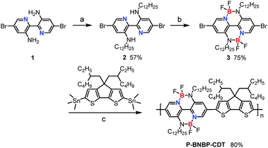
Scheme 1 shows the synthetic route of P-BNBP-CDT. The two monomers were prepared following procedures previously published in the literature.9c,10aP-BNBP-CDT was synthesized via Stille-polymerization of the two monomers with Pd2(dba)3/P(o-tolyl)3 as the catalyst system. According to gel permeation chromatography (GPC) with 1,2,4-trichlorobenzene as the eluent at 150 °C, the number-average molecular weight (Mn) is 15.4 kDa and the polydispersity (PDI) is 1.88. According to thermogravimetric analysis (TGA), P-BNBP-CDT shows good thermal stability with a thermal decomposition temperature (Td) at 5% weight loss of over 380 °C (ESI†). In addition, the polymer exhibits good solubility in common organic solvents, including chloroform (CHCl3), chlorobenzene (CB), and o-dichlorobenzene (o-DCB).Absorption properties
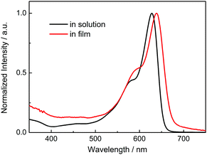
The absorption spectrum of P-BNBP-CDT in CHCl3 solution shows a strong absorption band from 500 to 650 nm with the main absorption peak at λ = 628 nm and a high molar absorption coefficient of 1.08 × 10⁵ M−1 cm−1 (Fig. 1). In the thin film, the absorption spectrum is red-shifted by 20 nm due to intermolecular interactions in the aggregation state. According to the onset absorption wavelength in the film, the optical bandgap of P-BNBP-CDT is estimated to be 1.85 eV. The strong absorption in the visible range of P-BNBP-CDT is expected to improve the solar light absorption of the active layer of all-PSCs (Table 1).| λ abs (nm) | ε max (M−1 cm−1) | λ em (nm) | λ abs (nm) | λ onset (nm) |
E
optg![[thin space (1/6-em)]](https://www.rsc.org/images/entities/char_2009.gif) b (eV) b (eV) |
E oxonset (V) | E redonset (V) | E HOMO (eV) | E LUMO (eV) |
E
elecg![[thin space (1/6-em)]](https://www.rsc.org/images/entities/char_2009.gif) b (eV) b (eV) |
|---|---|---|---|---|---|---|---|---|---|---|
| a Measured in dilute CHCl3 solution. b Measured in thin film. c Onset potential vs. Fc/Fc+. d Calculated using the equations (EHOMO = −(4.80 + Eoxonset) eV, ELUMO = −(4.80 + Eredonset) eV). | ||||||||||
| 628 | 108![[thin space (1/6-em)]](https://www.rsc.org/images/entities/char_2009.gif) 000 000 |
655 | 648 | 670 | 1.85 | +0.84 | −1.35 | −5.64 | −3.45 | 2.19 |
Fluorescence properties
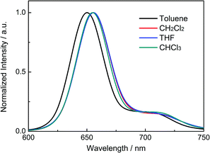
Fig. 2 shows the fluorescence spectra of P-BNBP-CDT in organic solvents with different polarities, including toluene, CH2Cl2, THF and CHCl3. The fluorescence peaks of P-BNBP-CDT in various organic solvents are all around 655 nm, which are almost insensitive to the polarities of solvents. It is well known that D–A type conjugated molecules or polymers (alternating electron-rich unit and electron-deficient unit) usually exhibit red-shifted fluorescence peaks in polar solvents compared to in non-polar solvents. Therefore, the absence of solvatochromic effects of P-BNBP-CDT confirms that P-BNBP-CDT is not a typical D–A type conjugated polymer. This is fully consistent with the theoretical calculation results of P-BNBP-CDT, which show both the delocalized LUMO and the delocalized HOMO over the polymer backbones (vide infra).Theoretical calculations
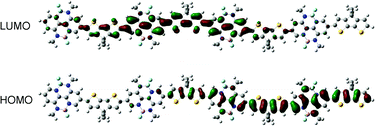
To elucidate the polymer backbone configuration and electronic structure of P-BNBP-CDT, density functional theory (DFT) calculations at the B3LYP/6-31G* level of theory were performed using the model compound containing four repeating units with the long alkyl chains replaced by methyl groups.12 As shown in Fig. 3, the model compound of P-BNBP-CDT exhibits a “wavy” backbone configuration. A slight twisted conformation is observed with an optimized twist angle of 21° between the BNBP and CDT units. It is noteworthy that both the calculated LUMO and HOMO of the model compound are delocalized over the electron-deficient BNBP units and the electron-rich CDT units. These delocalized molecular orbitals are similarly observed in the reported BNBP-based polymers, suggesting that BNBP-containing conjugated polymers are not typical D–A type conjugated polymers, even if a highly electron-rich CDT unit is introduced in P-BNBP-CDT.Electrochemical properties
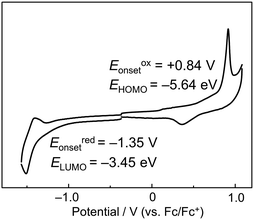
To further investigate the electronic structure of P-BNBP-CDT, cyclic voltammetry (CV) measurements were carried out with the thin film of P-BNBP-CDT. The ferrocene/ferrocenium (Fc/Fc+) reference was used as an internal standard, which was assigned an absolute energy of −4.80 eV vs. the vacuum level. As shown in Fig. 4, the cyclic voltammogram exhibits irreversible reduction and oxidation waves with the onset potentials of Eredonset = −1.35 V and Eoxonset = +0.84 V. Accordingly, the LUMO/HOMO energy levels of P-BNBP-CDT are estimated to be −3.45 eV/−5.64 eV. Its EHOMO/LUMO are higher than that of typical BNBP-based polymers, indicating that the electron-rich CDT unit can enhance the EHOMO/LUMO of P-BNBP-CDT due to its delocalized HOMO/LUMO. Moreover, its EHOMO/LUMO is higher than that (EHOMO/LUMO = −6.10 eV/−3.88 eV) of PC61BM by ca. 0.4 eV, suggesting that high Voc could be obtained in P-BNBP-CDT-based all-PSCs.Photovoltaic properties
The absorption properties and energy levels of P3HT and P-BNBP-CDT were compared. As shown in Fig. 5a, P3HT shows absorption between 400 and600 nm in the visible range, which is very complementary to that of P-BNBP-CDT. The ELUMO/HOMO offsets between P3HT and P-BNBP-CDT are 0.25 eV/0.44 eV, which could enable the photo-induced electron transfer from P3HT to P-BNBP-CDT and the photo-induced hole transfer from P-BNBP-CDT to P3HT. Thus, we used P-BNBP-CDT as the electron acceptor and P3HT as the electron donor to fabricate all-PSC devices. All-PSCs were fabricated with the configuration of ITO/PEDOT:PSS/P3HT:P-BNBP-CDT/LiF/Al. The active layer was spin-coated from the blend of donor![[thin space (1/6-em)]](https://www.rsc.org/images/entities/char_2009.gif) :
:![[thin space (1/6-em)]](https://www.rsc.org/images/entities/char_2009.gif) acceptor polymers in CHCl3 solution without any additives.
acceptor polymers in CHCl3 solution without any additives.
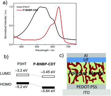 | ||
| Fig. 5 (a) UV/Vis absorption spectra of P-BNBP-CDT and P3HT in thin films; (b) the energy level alignments of P-BNBP-CDT and P3HT; (c) schematic of the all-PSC device structure. | ||
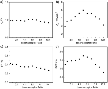
Fig. 6 shows the current density–voltage (J–V) curves and the external quantum efficiency (EQE) spectra of the P3HT:P-BNBP-CDT devices under AM 1.5G illumination (100 mW cm−2). The photovoltaic parameters are summarized in Fig. 7 and Table 2. The P3HT![[thin space (1/6-em)]](https://www.rsc.org/images/entities/char_2009.gif) :
:![[thin space (1/6-em)]](https://www.rsc.org/images/entities/char_2009.gif) P-BNBP-CDT (w
P-BNBP-CDT (w![[thin space (1/6-em)]](https://www.rsc.org/images/entities/char_2009.gif) :
:![[thin space (1/6-em)]](https://www.rsc.org/images/entities/char_2009.gif) w, 0.5
w, 0.5![[thin space (1/6-em)]](https://www.rsc.org/images/entities/char_2009.gif) :
:![[thin space (1/6-em)]](https://www.rsc.org/images/entities/char_2009.gif) 1) device exhibits a photovoltaic performance with an open-circuit voltage (Voc) of 0.99 V, a short-circuit current density (Jsc) of 2.96 mA cm−2, and a fill factor (FF) of 0.43, corresponding to a PCE of 1.26%. The preliminary device performance suggests enough ELUMO/HOMO offsets between P3HT and P-BNBP-CDT, and efficient charge separation in the blend.
1) device exhibits a photovoltaic performance with an open-circuit voltage (Voc) of 0.99 V, a short-circuit current density (Jsc) of 2.96 mA cm−2, and a fill factor (FF) of 0.43, corresponding to a PCE of 1.26%. The preliminary device performance suggests enough ELUMO/HOMO offsets between P3HT and P-BNBP-CDT, and efficient charge separation in the blend.
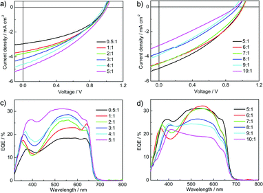 | ||
Fig. 6 (a and b) J–V curves and (c and d) EQE spectra of the P3HT![[thin space (1/6-em)]](https://www.rsc.org/images/entities/char_2009.gif) : :![[thin space (1/6-em)]](https://www.rsc.org/images/entities/char_2009.gif) P-BNBP-CDT devices with different donor P-BNBP-CDT devices with different donor![[thin space (1/6-em)]](https://www.rsc.org/images/entities/char_2009.gif) : :![[thin space (1/6-em)]](https://www.rsc.org/images/entities/char_2009.gif) acceptor blend ratios. acceptor blend ratios. | ||
Donor (w![[thin space (1/6-em)]](https://www.rsc.org/images/entities/char_2009.gif) : :![[thin space (1/6-em)]](https://www.rsc.org/images/entities/char_2009.gif) w) w) |
V oc (V) | J sc (mA cm−2) | J (cal.)sc (mA cm−2) | FF | PCEmax (%) | PCEavea (%) | EQE |
|---|---|---|---|---|---|---|---|
| a The average PCE value is calculated from four devices. | |||||||
P3HT (0.5![[thin space (1/6-em)]](https://www.rsc.org/images/entities/char_2009.gif) : :![[thin space (1/6-em)]](https://www.rsc.org/images/entities/char_2009.gif) 1) 1) |
0.99 | 2.96 | 2.83 | 0.43 | 1.26 | 1.15 | 0.18 |
P3HT (1![[thin space (1/6-em)]](https://www.rsc.org/images/entities/char_2009.gif) : :![[thin space (1/6-em)]](https://www.rsc.org/images/entities/char_2009.gif) 1) 1) |
0.98 | 3.56 | 3.48 | 0.41 | 1.44 | 1.32 | 0.25 |
P3HT (2![[thin space (1/6-em)]](https://www.rsc.org/images/entities/char_2009.gif) : :![[thin space (1/6-em)]](https://www.rsc.org/images/entities/char_2009.gif) 1) 1) |
0.99 | 3.73 | 3.66 | 0.40 | 1.47 | 1.38 | 0.26 |
P3HT (3![[thin space (1/6-em)]](https://www.rsc.org/images/entities/char_2009.gif) : :![[thin space (1/6-em)]](https://www.rsc.org/images/entities/char_2009.gif) 1) 1) |
0.98 | 4.16 | 4.02 | 0.36 | 1.48 | 1.36 | 0.29 |
P3HT (4![[thin space (1/6-em)]](https://www.rsc.org/images/entities/char_2009.gif) : :![[thin space (1/6-em)]](https://www.rsc.org/images/entities/char_2009.gif) 1) 1) |
0.97 | 4.60 | 4.49 | 0.35 | 1.57 | 1.44 | 0.27 |
P3HT (5![[thin space (1/6-em)]](https://www.rsc.org/images/entities/char_2009.gif) : :![[thin space (1/6-em)]](https://www.rsc.org/images/entities/char_2009.gif) 1) 1) |
1.01 | 4.98 | 4.86 | 0.35 | 1.76 | 1.67 | 0.31 |
P3HT (6![[thin space (1/6-em)]](https://www.rsc.org/images/entities/char_2009.gif) : :![[thin space (1/6-em)]](https://www.rsc.org/images/entities/char_2009.gif) 1) 1) |
1.01 | 4.56 | 4.42 | 0.37 | 1.69 | 1.60 | 0.32 |
P3HT (7![[thin space (1/6-em)]](https://www.rsc.org/images/entities/char_2009.gif) : :![[thin space (1/6-em)]](https://www.rsc.org/images/entities/char_2009.gif) 1) 1) |
1.00 | 4.59 | 4.45 | 0.34 | 1.58 | 1.49 | 0.31 |
P3HT (8![[thin space (1/6-em)]](https://www.rsc.org/images/entities/char_2009.gif) : :![[thin space (1/6-em)]](https://www.rsc.org/images/entities/char_2009.gif) 1) 1) |
0.95 | 4.14 | 4.02 | 0.32 | 1.26 | 1.15 | 0.26 |
P3HT (9![[thin space (1/6-em)]](https://www.rsc.org/images/entities/char_2009.gif) : :![[thin space (1/6-em)]](https://www.rsc.org/images/entities/char_2009.gif) 1) 1) |
0.94 | 3.88 | 3.77 | 0.30 | 1.10 | 1.01 | 0.24 |
P3HT (10![[thin space (1/6-em)]](https://www.rsc.org/images/entities/char_2009.gif) : :![[thin space (1/6-em)]](https://www.rsc.org/images/entities/char_2009.gif) 1) 1) |
0.92 | 3.12 | 3.01 | 0.27 | 0.79 | 0.68 | 0.21 |
The all-PSC devices were carefully optimized and the effects of the blend ratios were investigated (Fig. 6). The thicknesses of the blend films are in the range of 80–100 nm. When increasing the blend ratios of the devices from 0.5![[thin space (1/6-em)]](https://www.rsc.org/images/entities/char_2009.gif) :
:![[thin space (1/6-em)]](https://www.rsc.org/images/entities/char_2009.gif) 1 to 5
1 to 5![[thin space (1/6-em)]](https://www.rsc.org/images/entities/char_2009.gif) :
:![[thin space (1/6-em)]](https://www.rsc.org/images/entities/char_2009.gif) 1, the Jsc and PCE values gradually enhance. Upon further increasing the blend ratios of the devices from 5
1, the Jsc and PCE values gradually enhance. Upon further increasing the blend ratios of the devices from 5![[thin space (1/6-em)]](https://www.rsc.org/images/entities/char_2009.gif) :
:![[thin space (1/6-em)]](https://www.rsc.org/images/entities/char_2009.gif) 1 to 10
1 to 10![[thin space (1/6-em)]](https://www.rsc.org/images/entities/char_2009.gif) :
:![[thin space (1/6-em)]](https://www.rsc.org/images/entities/char_2009.gif) 1, the Jsc and PCE values exhibit decreasing trends (Fig. 7). The Voc and FF values show small changes in the variations of donor
1, the Jsc and PCE values exhibit decreasing trends (Fig. 7). The Voc and FF values show small changes in the variations of donor![[thin space (1/6-em)]](https://www.rsc.org/images/entities/char_2009.gif) :
:![[thin space (1/6-em)]](https://www.rsc.org/images/entities/char_2009.gif) acceptor ratios. Thus, the P3HT
acceptor ratios. Thus, the P3HT![[thin space (1/6-em)]](https://www.rsc.org/images/entities/char_2009.gif) :
:![[thin space (1/6-em)]](https://www.rsc.org/images/entities/char_2009.gif) P-BNBP-CDT (w
P-BNBP-CDT (w![[thin space (1/6-em)]](https://www.rsc.org/images/entities/char_2009.gif) :
:![[thin space (1/6-em)]](https://www.rsc.org/images/entities/char_2009.gif) w, 5
w, 5![[thin space (1/6-em)]](https://www.rsc.org/images/entities/char_2009.gif) :
:![[thin space (1/6-em)]](https://www.rsc.org/images/entities/char_2009.gif) 1) device shows the highest PCE of 1.76% with a Voc of 1.01 V, a Jsc of 4.98 mA cm−2 and a FF of 0.35. It is very attractive that the P3HT
1) device shows the highest PCE of 1.76% with a Voc of 1.01 V, a Jsc of 4.98 mA cm−2 and a FF of 0.35. It is very attractive that the P3HT![[thin space (1/6-em)]](https://www.rsc.org/images/entities/char_2009.gif) :
:![[thin space (1/6-em)]](https://www.rsc.org/images/entities/char_2009.gif) P-BNBP-CDT devices can give PCEs exceeding 1% with very high blend weight ratios from 0.5
P-BNBP-CDT devices can give PCEs exceeding 1% with very high blend weight ratios from 0.5![[thin space (1/6-em)]](https://www.rsc.org/images/entities/char_2009.gif) :
:![[thin space (1/6-em)]](https://www.rsc.org/images/entities/char_2009.gif) 1 to 9
1 to 9![[thin space (1/6-em)]](https://www.rsc.org/images/entities/char_2009.gif) :
:![[thin space (1/6-em)]](https://www.rsc.org/images/entities/char_2009.gif) 1. Moreover, these all-PSC devices produce a Voc of ca. 1.0 V, which is higher than that of the P3HT
1. Moreover, these all-PSC devices produce a Voc of ca. 1.0 V, which is higher than that of the P3HT![[thin space (1/6-em)]](https://www.rsc.org/images/entities/char_2009.gif) :
:![[thin space (1/6-em)]](https://www.rsc.org/images/entities/char_2009.gif) PC61BM device by 0.4 V. This is due to the higher ELUMO of P-BNBP-CDT compared with that of PC61BM. These results indicate that all-PSC devices can be fabricated using a large amount of P3HT with good device performance, suggesting the important potential for low cost and facile device processing of all-PSCs.11
PC61BM device by 0.4 V. This is due to the higher ELUMO of P-BNBP-CDT compared with that of PC61BM. These results indicate that all-PSC devices can be fabricated using a large amount of P3HT with good device performance, suggesting the important potential for low cost and facile device processing of all-PSCs.11
The EQE spectra of the P3HT:P-BNBP-CDT devices are shown in Fig. 6c and d. The all-PSC devices all show a broad EQE response from 300 nm to 700 nm, contributed from the absorption of both P3HT and P-BNBP-CDT. The P3HT![[thin space (1/6-em)]](https://www.rsc.org/images/entities/char_2009.gif) :
:![[thin space (1/6-em)]](https://www.rsc.org/images/entities/char_2009.gif) P-BNBP-CDT (w
P-BNBP-CDT (w![[thin space (1/6-em)]](https://www.rsc.org/images/entities/char_2009.gif) :
:![[thin space (1/6-em)]](https://www.rsc.org/images/entities/char_2009.gif) w, 0.5
w, 0.5![[thin space (1/6-em)]](https://www.rsc.org/images/entities/char_2009.gif) :
:![[thin space (1/6-em)]](https://www.rsc.org/images/entities/char_2009.gif) 1) device shows the maximum EQE of 0.18 in 500–600 nm. When increasing the blend ratios of the devices from 0.5
1) device shows the maximum EQE of 0.18 in 500–600 nm. When increasing the blend ratios of the devices from 0.5![[thin space (1/6-em)]](https://www.rsc.org/images/entities/char_2009.gif) :
:![[thin space (1/6-em)]](https://www.rsc.org/images/entities/char_2009.gif) 1 to 5
1 to 5![[thin space (1/6-em)]](https://www.rsc.org/images/entities/char_2009.gif) :
:![[thin space (1/6-em)]](https://www.rsc.org/images/entities/char_2009.gif) 1, the maximum EQE values gradually increase to 0.31. Upon further increasing the blend ratios from 5
1, the maximum EQE values gradually increase to 0.31. Upon further increasing the blend ratios from 5![[thin space (1/6-em)]](https://www.rsc.org/images/entities/char_2009.gif) :
:![[thin space (1/6-em)]](https://www.rsc.org/images/entities/char_2009.gif) 1 to 10
1 to 10![[thin space (1/6-em)]](https://www.rsc.org/images/entities/char_2009.gif) :
:![[thin space (1/6-em)]](https://www.rsc.org/images/entities/char_2009.gif) 1, the maximum EQE values decreased. The Jsc values calculated from the integration of EQE spectra with the AM 1.5G spectrum are consistent with the Jsc values obtained from the J–V scans within 10% error.
1, the maximum EQE values decreased. The Jsc values calculated from the integration of EQE spectra with the AM 1.5G spectrum are consistent with the Jsc values obtained from the J–V scans within 10% error.
We also investigated the charge carrier mobilities of the blend films using the space-charge-limited current (SCLC) method with the electron-only and hole-only devices (ESI†). The data are shown in Fig. S10 and listed in Table S2 (ESI†). In the active layers, the hole/electron mobility (μh/μe) ratios are 6/1 for the P3HT![[thin space (1/6-em)]](https://www.rsc.org/images/entities/char_2009.gif) :
:![[thin space (1/6-em)]](https://www.rsc.org/images/entities/char_2009.gif) P-BNBP-CDT (w
P-BNBP-CDT (w![[thin space (1/6-em)]](https://www.rsc.org/images/entities/char_2009.gif) :
:![[thin space (1/6-em)]](https://www.rsc.org/images/entities/char_2009.gif) w, 0.5
w, 0.5![[thin space (1/6-em)]](https://www.rsc.org/images/entities/char_2009.gif) :
:![[thin space (1/6-em)]](https://www.rsc.org/images/entities/char_2009.gif) 1) blend, 8/1 for the P3HT
1) blend, 8/1 for the P3HT![[thin space (1/6-em)]](https://www.rsc.org/images/entities/char_2009.gif) :
:![[thin space (1/6-em)]](https://www.rsc.org/images/entities/char_2009.gif) P-BNBP-CDT (w
P-BNBP-CDT (w![[thin space (1/6-em)]](https://www.rsc.org/images/entities/char_2009.gif) :
:![[thin space (1/6-em)]](https://www.rsc.org/images/entities/char_2009.gif) w, 5
w, 5![[thin space (1/6-em)]](https://www.rsc.org/images/entities/char_2009.gif) :
:![[thin space (1/6-em)]](https://www.rsc.org/images/entities/char_2009.gif) 1) blend, and 46/1 for the P3HT
1) blend, and 46/1 for the P3HT![[thin space (1/6-em)]](https://www.rsc.org/images/entities/char_2009.gif) :
:![[thin space (1/6-em)]](https://www.rsc.org/images/entities/char_2009.gif) P-BNBP-CDT (w
P-BNBP-CDT (w![[thin space (1/6-em)]](https://www.rsc.org/images/entities/char_2009.gif) :
:![[thin space (1/6-em)]](https://www.rsc.org/images/entities/char_2009.gif) w, 9
w, 9![[thin space (1/6-em)]](https://www.rsc.org/images/entities/char_2009.gif) :
:![[thin space (1/6-em)]](https://www.rsc.org/images/entities/char_2009.gif) 1) blend, respectively. The relatively balanced charge carrier mobilities of the P3HT
1) blend, respectively. The relatively balanced charge carrier mobilities of the P3HT![[thin space (1/6-em)]](https://www.rsc.org/images/entities/char_2009.gif) :
:![[thin space (1/6-em)]](https://www.rsc.org/images/entities/char_2009.gif) P-BNBP-CDT (w
P-BNBP-CDT (w![[thin space (1/6-em)]](https://www.rsc.org/images/entities/char_2009.gif) :
:![[thin space (1/6-em)]](https://www.rsc.org/images/entities/char_2009.gif) w, 0.5
w, 0.5![[thin space (1/6-em)]](https://www.rsc.org/images/entities/char_2009.gif) :
:![[thin space (1/6-em)]](https://www.rsc.org/images/entities/char_2009.gif) 1 and 5
1 and 5![[thin space (1/6-em)]](https://www.rsc.org/images/entities/char_2009.gif) :
:![[thin space (1/6-em)]](https://www.rsc.org/images/entities/char_2009.gif) 1) devices are consistent with their good FF values.
1) devices are consistent with their good FF values.
Based on these experimental results, it is reasonable that the P3HT![[thin space (1/6-em)]](https://www.rsc.org/images/entities/char_2009.gif) :
:![[thin space (1/6-em)]](https://www.rsc.org/images/entities/char_2009.gif) P-BNBP-CDT (w
P-BNBP-CDT (w![[thin space (1/6-em)]](https://www.rsc.org/images/entities/char_2009.gif) :
:![[thin space (1/6-em)]](https://www.rsc.org/images/entities/char_2009.gif) w, 5
w, 5![[thin space (1/6-em)]](https://www.rsc.org/images/entities/char_2009.gif) :
:![[thin space (1/6-em)]](https://www.rsc.org/images/entities/char_2009.gif) 1) device shows the best device performance. Increasing the P3HT
1) device shows the best device performance. Increasing the P3HT![[thin space (1/6-em)]](https://www.rsc.org/images/entities/char_2009.gif) :
:![[thin space (1/6-em)]](https://www.rsc.org/images/entities/char_2009.gif) P-BNBP-CDT weight ratios from 0.5
P-BNBP-CDT weight ratios from 0.5![[thin space (1/6-em)]](https://www.rsc.org/images/entities/char_2009.gif) :
:![[thin space (1/6-em)]](https://www.rsc.org/images/entities/char_2009.gif) 1 to 5
1 to 5![[thin space (1/6-em)]](https://www.rsc.org/images/entities/char_2009.gif) :
:![[thin space (1/6-em)]](https://www.rsc.org/images/entities/char_2009.gif) 1 can enhance light absorption in the range of 350–600 nm from P3HT and keep the balanced charge carrier mobilities, which probably results in increasing the Jsc values and maintaining the FF values. Further increasing the P3HT
1 can enhance light absorption in the range of 350–600 nm from P3HT and keep the balanced charge carrier mobilities, which probably results in increasing the Jsc values and maintaining the FF values. Further increasing the P3HT![[thin space (1/6-em)]](https://www.rsc.org/images/entities/char_2009.gif) :
:![[thin space (1/6-em)]](https://www.rsc.org/images/entities/char_2009.gif) P-BNBP-CDT weight ratios from 5
P-BNBP-CDT weight ratios from 5![[thin space (1/6-em)]](https://www.rsc.org/images/entities/char_2009.gif) :
:![[thin space (1/6-em)]](https://www.rsc.org/images/entities/char_2009.gif) 1 to 9
1 to 9![[thin space (1/6-em)]](https://www.rsc.org/images/entities/char_2009.gif) :
:![[thin space (1/6-em)]](https://www.rsc.org/images/entities/char_2009.gif) 1 leads to the imbalance of charge carrier mobilities and poor exciton dissociation due to the small amount of P-BNBP-CDT, probably decreasing the Jsc and FF values. As a result, while the P3HT
1 leads to the imbalance of charge carrier mobilities and poor exciton dissociation due to the small amount of P-BNBP-CDT, probably decreasing the Jsc and FF values. As a result, while the P3HT![[thin space (1/6-em)]](https://www.rsc.org/images/entities/char_2009.gif) :
:![[thin space (1/6-em)]](https://www.rsc.org/images/entities/char_2009.gif) P-BNBP-CDT devices produce PCEs exceeding 1% with high blend weight ratios, the P3HT
P-BNBP-CDT devices produce PCEs exceeding 1% with high blend weight ratios, the P3HT![[thin space (1/6-em)]](https://www.rsc.org/images/entities/char_2009.gif) :
:![[thin space (1/6-em)]](https://www.rsc.org/images/entities/char_2009.gif) P-BNBP-CDT (w
P-BNBP-CDT (w![[thin space (1/6-em)]](https://www.rsc.org/images/entities/char_2009.gif) :
:![[thin space (1/6-em)]](https://www.rsc.org/images/entities/char_2009.gif) w, 5
w, 5![[thin space (1/6-em)]](https://www.rsc.org/images/entities/char_2009.gif) :
:![[thin space (1/6-em)]](https://www.rsc.org/images/entities/char_2009.gif) 1) device shows the best device performance.
1) device shows the best device performance.
At last, the morphology of the optimal P3HT:P-BNBP-CDT device was characterized using transmission electron microscopy (TEM) and atomic force microscopy (AFM) (Fig. 8). The TEM image exhibits nanostructures with uniform fibrous aggregation and no large-size aggregation can be observed. The AFM height and phase images of the blend exhibit fine phase-separation morphology with domain sizes of around 20–40 nm and a smooth surface with a root-mean-square (RMS) roughness of 1.21 nm. Such a phase separation morphology is very beneficial for all-PSCs.
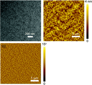 | ||
Fig. 8 (a) The TEM image and (b and c) the AFM height and phase images of the P3HT![[thin space (1/6-em)]](https://www.rsc.org/images/entities/char_2009.gif) : :![[thin space (1/6-em)]](https://www.rsc.org/images/entities/char_2009.gif) P-BNBP-CDT (w P-BNBP-CDT (w![[thin space (1/6-em)]](https://www.rsc.org/images/entities/char_2009.gif) : :![[thin space (1/6-em)]](https://www.rsc.org/images/entities/char_2009.gif) w, 5 w, 5![[thin space (1/6-em)]](https://www.rsc.org/images/entities/char_2009.gif) : :![[thin space (1/6-em)]](https://www.rsc.org/images/entities/char_2009.gif) 1) blend, respectively. 1) blend, respectively. | ||
Conclusions
In conclusion, we have developed a new conjugated polymer composed of alternating BNBP and CDT units. P-BNBP-CDT exhibits strong light absorption in the visible range and suitable LUMO/HOMO energy levels, which match well with those of P3HT. All-PSCs with P-BNBP-CDT as the acceptor and P3HT as the donor exhibit PCE values exceeding 1.0% with high donor![[thin space (1/6-em)]](https://www.rsc.org/images/entities/char_2009.gif) :
:![[thin space (1/6-em)]](https://www.rsc.org/images/entities/char_2009.gif) acceptor blend ratios from 0.5
acceptor blend ratios from 0.5![[thin space (1/6-em)]](https://www.rsc.org/images/entities/char_2009.gif) :
:![[thin space (1/6-em)]](https://www.rsc.org/images/entities/char_2009.gif) 1 to 9
1 to 9![[thin space (1/6-em)]](https://www.rsc.org/images/entities/char_2009.gif) :
:![[thin space (1/6-em)]](https://www.rsc.org/images/entities/char_2009.gif) 1, with the highest PCE of 1.76% with a high donor
1, with the highest PCE of 1.76% with a high donor![[thin space (1/6-em)]](https://www.rsc.org/images/entities/char_2009.gif) :
:![[thin space (1/6-em)]](https://www.rsc.org/images/entities/char_2009.gif) acceptor blend ratio of 5
acceptor blend ratio of 5![[thin space (1/6-em)]](https://www.rsc.org/images/entities/char_2009.gif) :
:![[thin space (1/6-em)]](https://www.rsc.org/images/entities/char_2009.gif) 1. These results not only indicate that BNBP-based polymers are promising for P3HT
1. These results not only indicate that BNBP-based polymers are promising for P3HT![[thin space (1/6-em)]](https://www.rsc.org/images/entities/char_2009.gif) :
:![[thin space (1/6-em)]](https://www.rsc.org/images/entities/char_2009.gif) polymer acceptor devices, but also show the potential for low cost and facile device processing of all-PSCs.
polymer acceptor devices, but also show the potential for low cost and facile device processing of all-PSCs.
Experimental section
Materials
Commercially available solvents and reagents were used without further purification unless otherwise mentioned. Ether, toluene, THF and CH2Cl2 were dried using sodium or calcium hydroxide before use. n-BuLi (2.5 M in hexane) was purchased from J&K Chemical Industries and used as received.Measurements and characterization
1H, 13C and 11B NMR spectra were measured using a Bruker AV-400 (400 MHz for 1H, 100 MHz for 13C and 128 MHz for 11B) spectrometer in CDCl3 at 25 °C. Chemical shifts are reported in δ ppm using CHCl3 (7.26 ppm) as the internal standard for 1H NMR and using CDCl3 (77.16 ppm) as the internal standard for 13C NMR. The external standard of BF3·OEt2 was used for the 11B NMR spectrum. Elemental analysis was performed on a VarioEL elemental analyzer. The molecular weight of the polymer was determined using gel permeation chromatography (GPC) on a PL-GPC 220-type at a temperature of 150 °C. 1,2,4-Trichlorobenzene (TCB) was used as the eluent and monodisperse polystyrene was used as the standard. UV/Vis absorption spectra and fluorescence spectra were measured using a Shimadzu UV-3600 spectrometer and a Hitachi F-4500 spectrometer, respectively, in spectral grade solvents. Thermal analyses were performed on a Perkin-Elmer 7 instrument under a nitrogen flow at a heating rate of 10 °C min−1. The transmission electron microscope (TEM) image was obtained using a JEM-1011 (JEOL Co., Japan) operated at an accelerating voltage of 100 kV. Cyclic voltammetry (CV) was performed on a CHI660a electrochemical workstation using Bu4NClO4 (0.1 M) in acetonitrile as the electrolyte solution and ferrocene as the internal reference, at a scan rate of 100 mV S−1. The CV cell consisted of a glassy carbon electrode, a Pt wire counter electrode, and a standard calomel reference electrode. For CV measurements, the polymer was casted on the working electrode. The redox potentials were calibrated with ferrocene as the internal standard. The highest occupied molecular orbital (HOMO) and the lowest unoccupied molecular orbital (LUMO) energy levels of the materials were estimated using the following equations: EHOMO/LUMO = −(4.80 + Eoxonset/Eredonset) eV. All reactions were performed under an argon atmosphere.Synthesis
![[thin space (1/6-em)]](https://www.rsc.org/images/entities/char_2009.gif) 400, PDI = 1.88. Anal. calcd for C59H90B2F4N4S2: C, 69.67; H, 8.92; B, 2.13; F, 7.47; N, 5.51; S, 6.30. Found: C, 69.39; H, 8.98; N, 5.30; S, 6.45.
400, PDI = 1.88. Anal. calcd for C59H90B2F4N4S2: C, 69.67; H, 8.92; B, 2.13; F, 7.47; N, 5.51; S, 6.30. Found: C, 69.39; H, 8.98; N, 5.30; S, 6.45.
Fabrication and characterization of polymer solar cells
Indium tin oxide (ITO) glass substrates were cleaned via sequential ultrasonication in detergent, deionized water, acetone, and isopropyl alcohol, followed by drying at 120 °C for 30 min and treated with UV-ozone for 25 min. Then PEDOT:PSS (Baytron P Al 4083) was spin-coated on the ITO glass substrates at 5000 rpm for 40 s to give a thickness of 40 nm, followed by baking at 125 °C for 30 min. The active layer was spin-coated with the corresponding solution in CHCl3 (8 mg mL−1) at 2500 rpm for 60 s. Finally, the device was transferred to a vacuum chamber, and LiF (1 nm)/Al (100 nm) was sequentially deposited via thermal evaporation at a pressure of about 4 × 10⁻⁴ Pa. The active area of each device was 8 mm2. The current density (J–V) characteristics of the PSC devices were measured using a computer-controlled Keithley 236 source meter and an Oriel 150 W solar simulator with an AM 1.5G filter and a light intensity of 100 mW cm−2.Acknowledgements
This work was financially supported by the 973 Project (No. 2014CB643504), the Nature Science Foundation of China (No. 51373165, 21574129, 21404099), the “Thousand Talents Program” of China, the Strategic Priority Research Program of the Chinese Academy of Sciences (No. XDB12010200), the Youth Innovation Promotion Association of the Chinese Academy of Sciences, and the State Key Laboratory of Supramolecular Structure and Materials in Jilin University (No. sklssm201608).Notes and references
- (a) Y. Huang, E. J. Kramer, A. J. Heeger and G. C. Bazan, Chem. Rev., 2014, 114, 7006 Search PubMed; (b) A. J. Heeger, Adv. Mater., 2014, 26, 10 Search PubMed; (c) Z. He, C. Zhong, S. Su, M. Xu, H. Wu and Y. Cao, Nat. Photonics, 2012, 6, 591 Search PubMed; (d) A. C. Arias, J. D. MacKenzie, I. McCulloch, J. Rivnay and A. Salleo, Chem. Rev., 2010, 110, 3 Search PubMed.
- (a) L. Ye, S. Zhang, L. Huo, M. Zhang and J. Hou, Acc. Chem. Res., 2014, 47, 1595 Search PubMed; (b) L. Lu, T. Zheng, Q. Wu, A. M. Schneider, D. Zhao and L. Yu, Chem. Rev., 2015, 115, 12666 CrossRef CAS PubMed; (c) Y. F. Li, Acc. Chem. Res., 2012, 45, 723 Search PubMed; (d) Y. J. Cheng, S. H. Yang and C. S. Hsu, Chem. Rev., 2009, 109, 5868 Search PubMed.
- (a) L. Dou, J. You, Z. Hong, Z. Xu, G. Li, R. A. Street and Y. Yang, Adv. Mater., 2013, 25, 6642 Search PubMed; (b) S. Zhang, L. Ye, W. Zhao, B. Tang, Q. Wang and J. Hou, Sci. China: Chem., 2015, 58, 248 Search PubMed; (c) H. Song, H. Tong, Z. Xie, L. Wang and F. Wang, Chin. J. Polym. Sci., 2013, 31, 1117 Search PubMed; (d) Z. Lu, C. Li, C. Du, X. Gong and Z. Bo, Chin. J. Polym. Sci., 2013, 31, 901 Search PubMed; (e) Y. Liu, Z. A. Page, T. P. Russell and T. Emrick, Angew. Chem., Int. Ed., 2015, 54, 11485 Search PubMed.
- (a) G. Li, V. Shrotriya, J. S. Huang, Y. Yao, T. Moriarty, K. Emery and Y. Yang, Nat. Mater., 2005, 4, 864 Search PubMed; (b) W. Ma, C. Yang, X. Gong, K. Lee and A. J. Heeger, Adv. Funct. Mater., 2005, 15, 1617 Search PubMed; (c) Y. Kim, S. Cook, S. M. Tuladhar, S. A. Choulis, J. Nelson, J. R. Durrant, D. D. C. Bradley, M. Giles, I. MuCulloch, C. S. Ha and M. Ree, Nat. Mater., 2006, 5, 197 Search PubMed; (d) P. Cheng, Q. Q. Shi and X. W. Zhan, Acta Chim. Sin., 2015, 73, 252 Search PubMed.
- (a) L. Gao, Z.-G. Zhang, L. Xue, J. Min, J. Zhang, Z. Wei and Y. Li, Adv. Mater., 2016, 28, 1884 CrossRef CAS PubMed; (b) Y.-J. Hwang, B. A. E. Courtright, A. S. Ferreira, S. H. Tolbert and S. A. Jenekhe, Adv. Mater., 2015, 27, 4578 Search PubMed; (c) H. Benten, D. Mori, H. Ohkita and S. Ito, J. Mater. Chem. A, 2016, 4, 5340 Search PubMed; (d) W. Li, Y. An, M. M. Wienk and R. A. J. Janssen, J. Mater. Chem. A, 2015, 3, 6756 Search PubMed; (e) T. Kim, J.-H. Kim, T. E. Kang, C. Lee, H. Kang, M. Shin, C. Wang, B. Ma, U. Jeong, T.-S. Kim and B. J. Kim, Nat. Commun., 2015, 6, 8547 Search PubMed; (f) H. Kang, M. A. Uddin, C. Lee, K.-H. Kim, T. L. Nguyen, W. Lee, Y. Li, C. Wang, H. Y. Woo and B. Kim, J. Am. Chem. Soc., 2015, 137, 2359 Search PubMed.
- (a) Y.-J. Hwang, T. Earmme, B. A. E. Courtright, F. N. Eberle and S. A. Jenekhe, J. Am. Chem. Soc., 2015, 137, 4424 Search PubMed; (b) T. Earmme, Y.-J. Hwang, S. Subramaniyan and S. A. Jenekhe, Adv. Mater., 2014, 26, 6080 Search PubMed; (c) N. Zhou, A. S. Dudnik, T. I. N. G. Li, E. F. Manley, T. J. Aldrich, P. Guo, H.-C. Liao, Z. Chen, L. X. Chen, R. P. H. Chang, A. Facchetti, M. O. de la Cruz and T. J. Marks, J. Am. Chem. Soc., 2016, 138, 1240 Search PubMed; (d) C. Lee, H. Kang, W. Lee, T. Kim, K.-H. Kim, H. Y. Woo, C. Wang and B. J. Kim, Adv. Mater., 2015, 27, 2466 Search PubMed; (e) J. W. Jung, J. W. Jo, C.-C. Chueh, F. Liu, W. H. Jo, T. P. Russell and A. K.-Y. Jen, Adv. Mater., 2015, 27, 3310 Search PubMed; (f) L. Ye, X. Jiao, M. Zhou, S. Zhang, H. Yao, W. Zhao, A. Xia, H. Ade and J. Hou, Adv. Mater., 2015, 27, 6046 Search PubMed; (g) P. Cheng, L. Ye, X. Zhao, J. Hou, Y. Li and X. Zhan, Energy Environ. Sci., 2014, 7, 1351 RSC; (h) Y. Zhou, T. Kurosawa, W. Ma, Y. Guo, L. Fang, K. Vandewal, Y. Diao, C. Wang, Q. Yan, J. Reinspach, J. Mei, A. L. Appleton, G. I. Koleilat, Y. Gao, S. C. B. Mannsfeld, A. Salleo, H. Ade, D. Zhao and Z. Bao, Adv. Mater., 2014, 26, 3767 CrossRef CAS PubMed; (i) C. Mu, P. Liu, W. Ma, K. Jiang, J. B. Zhao, K. Zhang, Z. H. Chen, Z. H. Wei, Y. Yi, J. N. Wang, S. H. Yang, F. Huang, A. Faccheti, H. Ade and H. Yan, Adv. Mater., 2014, 26, 7224 Search PubMed; (j) E. J. Zhou, J. Z. Cong, K. Hashimoto and K. Tajima, Adv. Mater., 2013, 25, 6991 Search PubMed; (k) L. Xue, Y. Yang, Z.-G. Zhang, X. Dong, L. Gao, H. Bin, J. Zhang, Y. Yang and Y. Li, J. Mater. Chem. A, 2016, 4, 5810 Search PubMed.
- (a) M. Schubert, D. Dolfen, J. Frisch, S. Roland, R. Steyrleuthner, B. Stiller, Z. Chen, U. Scherf, N. Koch, A. Facchetti and D. Neher, Adv. Energy Mater., 2012, 2, 369 CrossRef CAS; (b) G. Shi, J. Yuan, X. Huang, Y. Lu, Z. Liu, J. Peng, G. Ding, S. Shi, J. Sun, K. Lu, H.-Q. Wang and W. Ma, J. Phys. Chem. C, 2015, 119, 25298 Search PubMed; (c) J. R. Moore, S. Albert-Seifried, A. Rao, S. Massip, B. Watts, D. J. Morgan, R. H. Friend, C. R. McNeill and H. Sirringhaus, Adv. Energy Mater., 2011, 1, 230 Search PubMed; (d) S. Fabiano, Z. Chen, S. Vahedi, A. Facchetti, B. Pignataroc and M. A. Loi, J. Mater. Chem., 2011, 21, 5891 Search PubMed.
- (a) S. Lee, S. Nam, H. Kim and Y. Kim, ACS Sustainable Chem. Eng., 2013, 1, 1280 Search PubMed; (b) W. Yu, D. Yang, X. Zhu, X. Wang, G. Tu, D. Fan, J. Zhang and C. Li, ACS Appl. Mater. Interfaces, 2014, 6, 2350 Search PubMed; (c) D. Mori, H. Benten, H. Ohkita, S. Ito and K. Miyake, ACS Appl. Mater. Interfaces, 2012, 4, 3325 Search PubMed.
- (a) R. Zhao, C. Dou, Z. Xie, J. Liu and L. Wang, Angew. Chem., Int. Ed., 2016, 55, 5313 Search PubMed; (b) C. Dou, Z. Ding, Z. Zhang, Z. Xie, J. Liu and L. Wang, Angew. Chem., Int. Ed., 2015, 54, 3648 Search PubMed; (c) Z. Zhang, Z. Ding, C. Dou, J. Liu and L. Wang, Polym. Chem., 2015, 6, 8029 RSC.
- (a) C. Dou, X. Long, Z. Ding, Z. Xie, J. Liu and L. Wang, Angew. Chem., Int. Ed., 2016, 55, 1436 CrossRef CAS PubMed; (b) X. Long, Z. Ding, C. Dou, J. Zhang, J. Liu and L. Wang, Adv. Mater., 2016, 28, 6504 Search PubMed; (c) Z. Ding, X. Long, C. Dou, J. Liu and L. Wang, Chem. Sci., 2016, 7, 6197 Search PubMed; (d) X. Long, N. Wang, Z. Ding, C. Dou, J. Liu and L. Wang, J. Mater. Chem. C, 2016, 4, 9961 Search PubMed.
- (a) D. Qian, W. Ma, Z. Li, X. Guo, S. Zhang, L. Ye, H. Ade, Z. Tan and J. Hou, J. Am. Chem. Soc., 2013, 135, 8464 Search PubMed; (b) J. Yuan, H. Dong, M. Li, X. Huang, J. Zhong, Y. Li and W. Ma, Adv. Mater., 2014, 26, 3624 Search PubMed.
- DFT calculations were performed using Gaussian 09 program: M. J. Frisch, et al., Gaussian 09, revision A.02, Gaussian, Inc., Wallingford, CT, 2009 Search PubMed For details, see ESI†.
Footnote |
| † Electronic supplementary information (ESI) available: Characterization and thermal properties of the polymer, as well as all-PSC device performance and charge-transporting properties. See DOI: 10.1039/c6qm00245e |
| This journal is © the Partner Organisations 2017 |

