DOI:
10.1039/C6QM00172F
(Research Article)
Mater. Chem. Front., 2017,
1, 716-726
Simultaneously improving the mechanical properties and flame retardancy of polypropylene using functionalized carbon nanotubes by covalently wrapping flame retardants followed by linking polypropylene†
Received
15th August 2016
, Accepted 3rd October 2016
First published on 24th October 2016
Abstract
The fabrication of polymer nanocomposites with improved physical and chemical properties is a hot topic in the fields of materials and chemistry. In this work, carbon nanotubes (CNTs) are functionalized through flame retardant wrapping and maleic anhydride polypropylene (PPMA) covalently attaching to achieve a compact char layer and strong interfacial adhesion. The resultant polypropylene (PP)/functionalized CNT (FCNT) composites show remarkably improved flame retardancy and mechanical properties. For example, with the incorporation of FCNTs, the mechanical properties of PP are largely improved, meanwhile the ductility is maintained. This is thanks to the strong interfacial adhesion between FCNTs and the PP matrix. In contrast, the elongation at break of the PP/CNT composites decreases seriously. More importantly, the flame retardancy of the PP/FCNT composites is much better than that of PP and the PP/CNT composites. The improved flame retardancy results from the fact that the flame retardant wrapping forms a char layer on the surface of the CNTs, which protects the CNTs from being destroyed during combustion. As a result, the quality of the residual char is improved. The flammability of the PP composites is strongly dependent on the residual char of the CNTs. The compact and continuous residual char of the FCNTs not only acts as the shield for heat transfer, but also hinders the migration of volatile decomposition products out of PP and the diffusion of oxygen into PP.
1. Introduction
Carbon nanotubes (CNTs) have found a number of exciting potential applications in various fields since their discovery, due to their remarkable electrical conductivity, and unique thermal and mechanical properties.1–4 Typically, CNTs have been demonstrated to be potentially ideal candidates for the fabrication of polymer composites with improved mechanical properties and electrical conductivity.5 The resultant polymer–CNT composites have displayed a multitude of potential applications.6,7 Interestingly, recent reports have demonstrated that the addition of CNTs endow the flammable polymers with remarkably improved flame retardancy.8–13 Kashiwagi et al. found that CNTs were efficient in improving the flame retardancy because of the formation of a network structure within the polymer matrix.14 However, for the polymer–CNT composites, there are still some challenges when fabricating multifunctional polymer composites with effective reinforcement. One challenge is that CNTs alone cannot form a strong network and a stable char layer during combustion due to their inherently poor thermal stability and their aggregation to form bundles of CNTs;15,16 the other is the poor polymer–CNT interfacial adhesion resulting from a lack of moieties on the surface of the CNTs, which often leads to a great decrease in ductility and toughness of the materials.17,18
The in situ formation of a stable protective layer covering the entire sample surface without openings or cracks during combustion is the key factor when enhancing flame retardancy.19 The combination of different nanoparticles or carbonization catalysts with CNTs is a potential way to form a compact char layer during combustion within the polymer matrix.20–23 Typically, Gong et al. found the synergistic effect of carbon fibers (CFs) and CNTs on improving the flame retardancy of PP, which was due to the accelerated crosslinking reaction of PP radicals and the in situ formation of a condense and continuous CF/CNT protective layer.24 Yu et al. demonstrated that the synergistic effect of CNTs and Ni2O3 on improving the flame retardancy of polyethylene (PE), resulting from the formation of a network-like structure composed of CNTs and carbonization products catalyzed by Ni2O3.25 The combination of CNTs with flame retardants, especially grafted with flame retardants, is another efficient way to achieve a compact layer.26,27 Ma et al. found that the addition of intumescent flame retardant (IFR) grafted CNTs improved the flame retardancy of an ABS resin, due to better dispersion of CNTs and dense char formation.28 Yu et al. grafted a char-forming polymer onto the surface of CNTs (CNT-PR), and the flame retardancy of the CNT-PR/epoxy resin greatly improved, which was ascribed to the good dispersion of CNT-PR and high char yield during combustion.29 Song et al. fabricated IFR wrapped CNTs with different degrees of functionalization, and the improved flame retardancy of PP was due to the good dispersion of the CNTs and the high char-forming capability of IFR.30 However, most of these previous studies focus on the flame retardancy of the composites, and other properties are rarely concerned. The interfacial adhesion between CNTs and the polymer matrix, especially the nonpolar polyolefins, still remains a challenge.
Owing to the incompatible and low interaction energy between polyolefins and nanofillers (such as graphene nanosheets (GNS) and CNTs), the composites prepared by melting mixing often show inferior dispersion and poor interfacial adhesion.31 Compared to non-covalent and covalent functionalization with small molecular modifiers, covalent linking of nanofillers with polymer chains provides higher load transfer efficiency and a stronger interaction between nanofillers and the polymer matrix.32,33 For instance, Yang et al. grafted PE onto amine-functionalized CNTs through melt mixing, and found that the stiffness, strength, ductility and toughness of the PE improved due to a good dispersion of CNTs and improved interfacial adhesion.34 Cao et al. grafted PP onto the surface of amine-functionalized GNS and used it as multifunctional compatibilizers for immiscible PP/polyphenylene oxide. They found that the thermal stability, mechanical strength and crystallization nucleation ability of the composites improved.35 However, most of the studies are limited to the dispersion and mechanical properties, and little attention has been paid to the flame retardancy of composites with the incorporation of polymer grafted CNTs. It is probable that the molecular modifiers or polymer chains grafted onto the CNTs often deteriorate the flame retardancy of the materials due to their inherent flammability. More interestingly, the dispersion of IFR in the polymer matrix, and the interfacial adhesion between IFR and the matrix, are found to be enhanced through covalently attached polymer chains to IFR.36
In this work, we report a novel facile strategy for the fabrication of PP/CNT composites with improved dispersion and interfacial adhesion. Firstly, CNTs were wrapped with IFR by in situ condensation polymerization to form a compact char layer during combustion, then the amine-terminal CNTs were covalently attached to the compatibilizer PPMA to improve the interfacial adhesion between the CNTs and PP, and finally PP/functionalized CNT (FCNT) composites were fabricated through melt mixing of the FCNTs with PP. The effect of FCNTs on the thermal stability, mechanical properties and flame retardancy of the PP composites were comprehensively investigated, and the related mechanism was discussed.
2. Experimental part
2.1 Materials
Polypropylene (PP, trademark T30S, MFI = 6.8 g min−1 at the temperature of 230 °C under pressure of 2.16 kg, Mw = 2.89 × 10⁵ g mol−1, polydispersity = 3.45, and melting point = 165.5 °C) powder was supplied by Daqing Petrochemical Co., Ltd, China. The maleic anhydride grafted PP (PPMA, MFI = 32 g min−1 at the temperature of 230 °C under pressure of 2.16 kg) with 0.8 wt% of maleic anhydride group was supplied by Starbetter (Beijing) Chemical Materials Co., China. Multi-walled CNTs with a purity >98% (the main metal impurities are nickel (0.86 wt%) and iron (0.04 wt%)), a diameter of 15 ± 5 nm and a length of ca. 30 μm were purchased from Chengdu Institute of Organic Chemistry, China. Phosphorus oxychloride (POCl3) and 2,6,7-trioxa-1-phosphabicyclo-[2,2,2]-octane-4-methanol (PEPA) were purchased from Fenghua materials Co., China. 4,4′-Diaminodiphenylmethane (DDM) was purchased from Sinopharm Chemical Reagent Co., Ltd, China. Tetrahydrofuran (THF), triethylamine (TEA) and acetonitrile were supplied by Fuchen Chemical Reagents Factory (Tianjin, China) and dried with 4 Å molecular sieves and distilled prior to use. Other agents were of analytical grade and used without further purifications.
2.2 Preparation of the PP/FCNT composites
2.2.1 Synthesis of the FCNTs.
FCNTs were fabricated through a four-step process, and the synthetic route is shown in Fig. 1. The hydroxylation of the purified CNTs was achieved according to a previous report.30 Typically, a certain amount of CNTs were immersed in a mixture of potassium hydroxide and ethanol, and then placed in an ultrasonic bath at 76 °C for 12 h. The resulting mixture was washed with ethanol and deionized water until reaching pH = 7, then the product was freeze-dried for 12 h and dried at 70 °C under a vacuum overnight. The resultant product was designated as CNT-OH. 0.5 g PEPA and 1.9 mL TEA were suspended in 20 mL CH3CN under a N2 atmosphere, then 0.4 mL POCl3 was slowly dripped into the mixture under an ice bath. The solution was maintained at 80 °C for 6 h and cooled to room temperature. Afterwards, the mixture of 1.0 g CNT-OH and 400 mL CH3CN, which had been undergoing ultrasonic treatment for 1 h, was transferred to the former mixture and reacted at 80 °C for 12 h. After that, the mixture of 0.8 g DDM in 10 mL CH3CN was dripped into the flask to start condensation polymerization. The reaction was allowed to continue at 80 °C for another 12 h. Then the mixture was completely washed with DMF, THF and deionized water. The resultant product was freeze-dried and then dried under reduced pressure at 70 °C for 12 h. The product was designated as CNT-PDBPP (i.e., poly(4,4-diamino diphenyl methane-O-bicyclicpentaerythritol phosphate-phosphate)). The synthesis of PDBPP followed the same procedures as those of CNT-PDBPP without the addition of CNTs.37
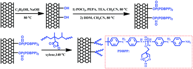 |
| | Fig. 1 Schematic synthetic routes towards FCNTs (the FCNT is a mixture of CNT-g-PPMA and unreacted PPMA). | |
PP was grafted onto the CNTs through the amidation reaction between the amine groups of CNT-PDBBP and the maleic anhydride groups of PPMA, as previously reported by other researchers.35 Briefly, 2.0 g of the as prepared CNT-PDBPP was suspended in 400 mL of xylene and put in an ultrasonic bath for 1 h. Subsequently, 4.0 g of PPMA was added. The mixture was then refluxed at 140 °C in the oil bath under N2 for 4 h and vacuum filtered with a PTFE membrane and washed with deionized water. The final product (FCNTs) was dried under reduced pressure at 80 °C for 12 h. To obtain samples for the characterization of the successfully grafted PPMA onto CNTs, some of the product was extracted with boiling toluene for 24 h.
2.2.2 Fabrication of the PP/FCNT composites.
PP/FCNT composites were prepared by mixing PP powder and FCNTs in a Haake batch intensive mixer (Haake Rheomix 600, Karlsruhe, Germany) at 100 rpm and 180 °C for 10 min. The resulting samples were designated as xFCNT, where x was the weight percentage of CNT-PDBPP in the composites. For comparison, PP composites with PPMA (the same content as that of the FCNTs) and CNTs were also prepared under the same conditions.
2.3 Characterization
An FTIR spectrum was recorded on a Vertex 70 FTIR spectrometer (Bruker, Germany) with KBr pellets. Spectra in the optical range of 500–4000 cm−1 were obtained by averaging 16 scans at a resolution of 4 cm−1. X-ray photoelectron spectroscopy (XPS) spectra were recorded with a VG ESCALAB MK II spectrometer using Al Kα exciting radiation from an X-ray source operated at 10.0 kV and 10 mA. The morphologies of the CNTs and CNT-PDBPP were studied using transmission electron microscopy (TEM) using a JEOL JEM-2100F microscope (JEOL Co., Ltd, Japan) with an acceleration voltage of 200 kV. CNTs and CNT-PDBPP were dispersed in ethanol with ultrasonication for 30 min. The dispersions were dripped onto copper grids for observation. Thermogravimetric analysis (TGA) was carried out using a Q600 thermal analyzer (TA Co., New Castle, USA) from ambient temperature to 700 °C at a heating rate of 10 °C min−1 under an air or nitrogen atmosphere with a flowing rate of 100 mL min−1. The mechanical properties were measured on an Instron 1121 at an extension speed of 10 mm min−1. All data were the average of five independent measurements; the relative errors committed on each data were reported as well. Cone calorimetry tests were performed using a Fire Testing Technology Ltd (West Sussex, UK) device according to ISO 5660 at an incident flux of 50 kW m−2. The samples were hot pressed by compression molding at 180 °C with a size of 100 mm × 100 mm × 6 mm square plaques. Each sample was mounted in aluminium foil and placed on a holder filled with a mineral fiber blanket, so that only the upper face was exposed to the radiant heater. All the samples were burned in triplicate, and the data were the average of three replicated tests. The limiting oxygen index (LOI) values were measured on an HC–2C oxygen index meter (Jingning Analysis Instrument Company, China) with sheet dimensions of 130 mm × 6.5 mm × 3 mm according to the ASTM D2863-97 standard. All the samples were tested fivefold, and the data used were the average of these five replicated tests. The photographs of the residual chars after cone calorimetry tests were collected using a digital camera. The microstructure of the residual chars was examined using FE-SEM (XL30 ESEM-FEG).
3. Results and discussion
3.1 Synthesis and characterization of the FCNTs
To prove the successful preparation of CNT-PDBPP and FCNTs, we used FTIR, XPS, TEM and TGA to characterize the products. The direct evidence of the obtained CNT-PDBPP and FCNTs was provided by using FTIR (Fig. 2). For CNT-OH, there is a broad absorption peak at around 3426 cm−1, which is attributed to the stretching vibration of O–H.30 PDBBP shows characteristic absorption peaks at 1298 cm−1 (P![[double bond, length as m-dash]](https://www.rsc.org/images/entities/char_e001.gif) O), 1020 cm−1 (P–O–C), 1614 cm−1, 1508 cm−1 and 1457 cm−1 (absorption peaks of phenyl), 1243 cm−1 and 965 cm−1 (P–N), 3381 cm−1 and 3210 cm−1 (N–H).36 The appearance of characteristic absorption peaks of PDBPP in the CNT-PDBPP, and the broad absorption peak at around 3432 cm−1 due to the absorption peaks of –OH overlapped with that of –NH2, confirm the successful wrapping of the CNTs by IFR. After the reaction with PPMA, the strong bands between 2965 and 2833 cm−1 are ascribed to the asymmetric and symmetric stretching vibration of the methyl and methylene groups.31 The absorption at 1453 cm−1 corresponds to the C–N stretching of the amide groups.35 These results confirm that the CNTs are successfully wrapped by PDBPP and covalently bonding onto the PP chains.
O), 1020 cm−1 (P–O–C), 1614 cm−1, 1508 cm−1 and 1457 cm−1 (absorption peaks of phenyl), 1243 cm−1 and 965 cm−1 (P–N), 3381 cm−1 and 3210 cm−1 (N–H).36 The appearance of characteristic absorption peaks of PDBPP in the CNT-PDBPP, and the broad absorption peak at around 3432 cm−1 due to the absorption peaks of –OH overlapped with that of –NH2, confirm the successful wrapping of the CNTs by IFR. After the reaction with PPMA, the strong bands between 2965 and 2833 cm−1 are ascribed to the asymmetric and symmetric stretching vibration of the methyl and methylene groups.31 The absorption at 1453 cm−1 corresponds to the C–N stretching of the amide groups.35 These results confirm that the CNTs are successfully wrapped by PDBPP and covalently bonding onto the PP chains.
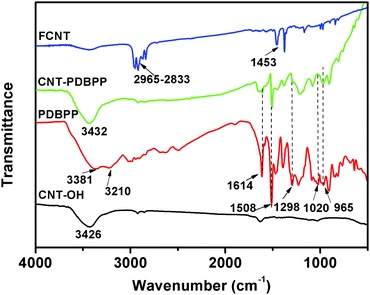 |
| | Fig. 2 FTIR spectra of CNT-OH, PDBPP, CNT-PDBPP and FCNTs. | |
TEM images provide the microstructure information of the CNTs and CNT-PDBPP (Fig. 3). As shown in Fig. 3a, the surface of the CNTs is relatively smooth and clear without an extra phase. Furthermore, the hollow core and open ends are found in the CNTs in Fig. 3c. Obviously, the morphology of CNT-PDBPP greatly changed after the CNTs were wrapped by IFR (Fig. 3b). The surface becomes rough and is uniformly covered by an IFR layer. From Fig. 3d, the thickness of the layer was measured to be ca. 15–25 nm. What is more, there is no dissociative flame retardant among the spaces of the CNTs, which proves that the dissociative flame retardant is totally removed.
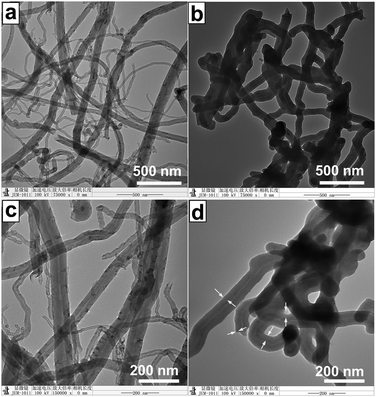 |
| | Fig. 3 TEM images of (a) and (c) CNTs; (b) and (d) CNT-PDBPP. The white arrows represent the IFR layer of CNT-PDBPP. | |
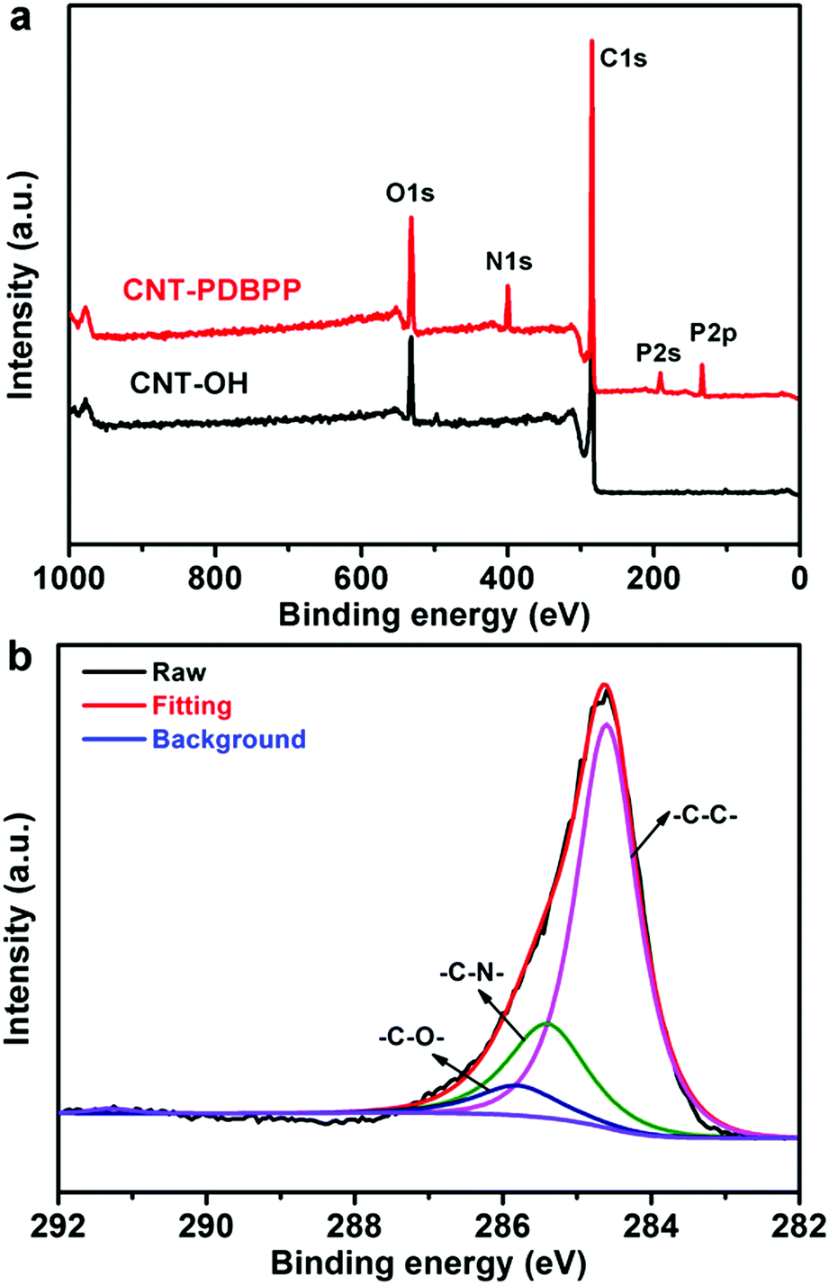
XPS measurement is used to characterize the elemental changes of the surface chemical composition of the related products (Fig. 4). For CNT-OH, the XPS profile shows the strong C1s peak (284.6 eV) and O1s peak (529.6 eV), indicating the successful hydroxylation of the CNTs.30 Compared to CNT-OH, CNT-PDBPP displays three new peaks at 134.0 eV (P2p), 189.2 eV (P2s) and 399.8 eV (N1s) (Fig. 4a). To clarify the binding type of the carbon atoms, we obtained a high resolution C1s XPS spectrum of CNT-PDBPP. As shown in Fig. 4b, CNT-PDBBP presents three peaks at 284.6 eV (C–C), 285.5 eV (C–N) and 285.8 eV (C–O and P–O–C).38,39 The bands related to CO and C(O)OH are not perceptible, probably due to the wrapping effect of the flame retardant.38 The results obtained using XPS prove that the CNTs are covalently attached by IFR, which is consistent with the results of FTIR.
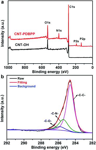 |
| | Fig. 4 (a) XPS spectrum of CNT-OH and CNT-PDBPP, and (b) high-resolution C1s XPS spectrum of CNT-PDBPP. | |
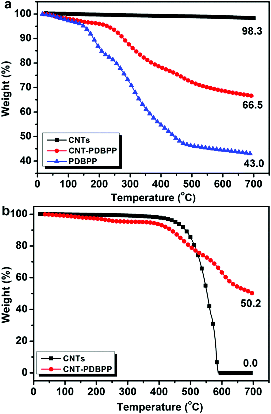
To measure the content of the IFR grafted onto the CNTs, we conducted TGA measurements for pristine CNTs, CNT-PDBPP and PDBPP under a nitrogen atmosphere (Fig. 5a). The CNTs hardly decomposed at a temperature below 700 °C and with a char residue of 98.3 wt%. PDBPP showed a char residue of 43.0 wt% at 700 °C. In the case of CNT-PDBPP, the degradation tendency was similar to that of PDBPP and left a char residue of 66.5 wt% at 700 °C. Considering the weight loss almost from the degradation of the grafted PDBPP, we roughly calculated that the grafted IFR was about 60 wt%. TGA curves of the CNTs and CNT-PDBPP under an air atmosphere are shown in Fig. 5b. The CNTs started to degrade seriously at 450 °C and no char was left at 600 °C. However, after being wrapped by the IFR, CNT-PDBPP left a high char residue up to 50.2 wt% at 700 °C, which clearly proved that the wrapped IFR protected the CNTs from serious degradation during heating.
 |
| | Fig. 5 TGA curves of (a) pristine CNTs, CNT-PDBPP and PDBPP under a nitrogen atmosphere, and (b) CNTs and CNT-PDBPP under an air atmosphere. | |
3.2 The dispersion states of the CNTs and FCNTs in the PP matrix
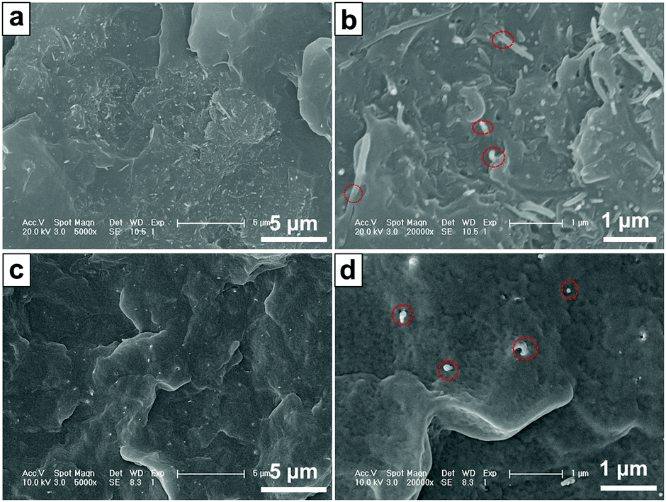
The dispersion states of the CNTs and FCNTs in the PP matrix were characterized using SEM. Fig. 6 shows the SEM photographs of the brittle-fractured surfaces of the PP composites. Because of strong interaction and entanglements, CNTs tend to aggregate, which results in non-uniform dispersion in the PP matrix. In Fig. 6a, some aggregate bundles of CNTs are observed in the 3CNT composite. An enlarged image of the aggregate parts shows that many of the CNTs are pulled out (Fig. 6b), which is ascribed to poor PP-CNT adhesion.34 In the case of the PP/FCNT composites, the FCNTs are dispersed uniformly in the PP matrix (Fig. 6c). This is because free-drying and grinding CNTs have been used after each modification steps of the CNTs to weaken the entanglements of the CNTs, and the wrapped IFR protects the CNTs from entangling with each other. The high resolution SEM image (Fig. 6d) shows that most of the CNTs are broken rather than pulled out, which results from the strong PP–FCNT interfacial adhesion.34
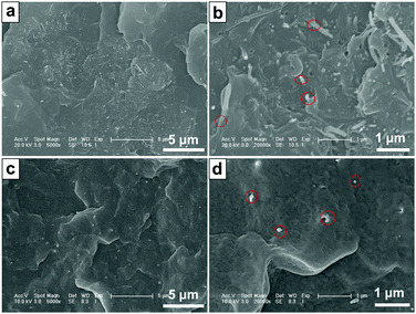 |
| | Fig. 6 Typical FE-SEM images of the brittle-fractured surfaces of the PP composites: (a) and (b) 3CNT; (c) and (d) 3FCNT. The red circles represent CNTs and FCNTs on the fractured structure. | |
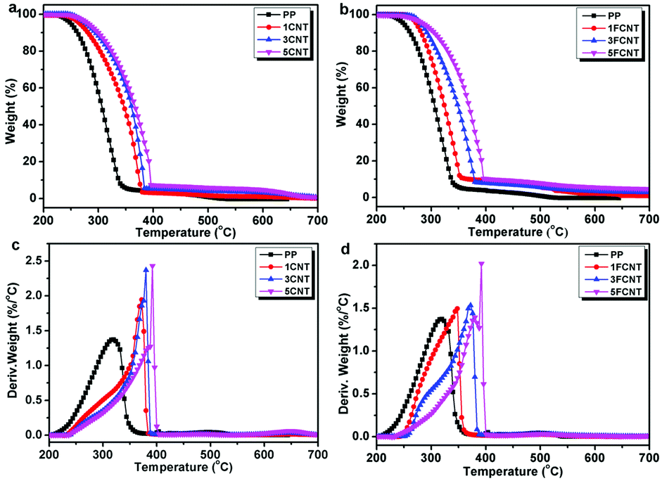
3.3 Thermal stabilities
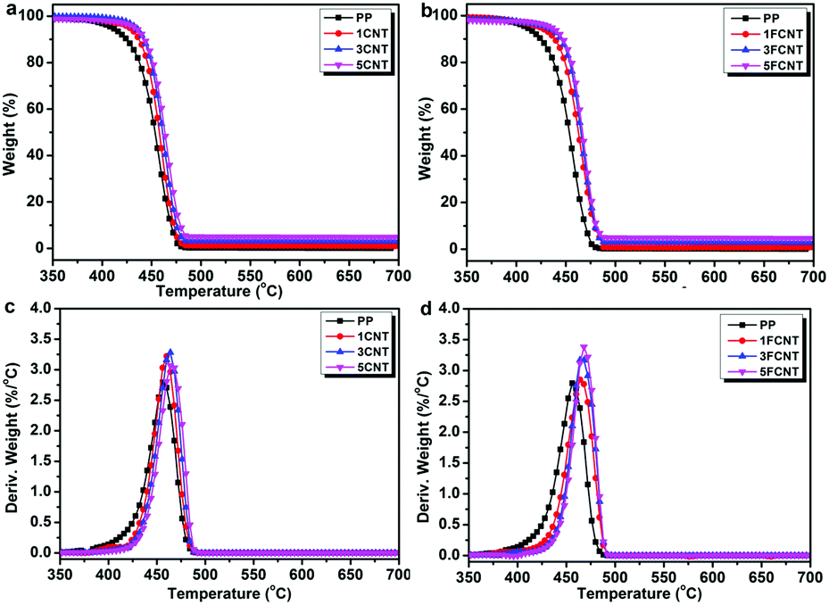
The thermal stabilities and thermal oxidation degradations of the PP/CNT and PP/FCNT composites were characterized using TGA under a nitrogen and air atmosphere (Fig. 7 and 8), and the detailed data are listed in Tables 1 and 2, respectively. The temperature at which 5 wt% weight loss occurred (T5wt%) and the temperature at which the maximum weight loss rate occurred (Tmax) are important thermal parameters, which reflect the initial decomposition temperature and the temperature at which the maximum decomposition rate of the materials occurs. Under the nitrogen atmosphere, PP started to degrade at 409 °C and the Tmax occurred at 457 °C with no residual char. In contrast, the addition of CNTs and FCNTs improved the thermal stability of PP. In particular, the T5wt% of the FCNT composites was somewhat lower than that of the CNT composites, which might result from decomposition of the grafted IFR. However, the Tmax of the FCNT composites was higher than that of the CNT composites, which might be ascribed to the trapping radical effect of the grafted IFR and the crosslinking reaction between IFR and PPMA during thermal decomposition.36
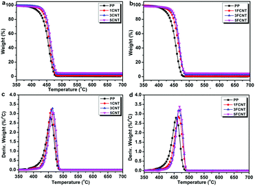 |
| | Fig. 7 TGA curves of (a) PP/CNT and (b) PP/FCNT composites, and DTG curves of (c) PP/CNT and (d) PP/FCNT composites under a nitrogen atmosphere at 10 °C min−1. | |
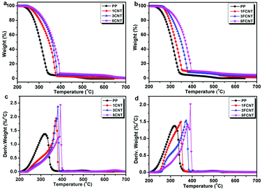 |
| | Fig. 8 TGA curves of (a) PP/CNT and (b) PP/FCNT composites, and DTG curves of (c) PP/CNT and (d) PP/FCNT composites under an air atmosphere at 10 °C min−1. | |
Table 1 Summary of the TGA results of PP and its composites under a nitrogen atmosphere
| Sample |
T
5wt%
(°C) |
T
max
(°C) |
Residue (wt%) |
|
T
5wt% represents the temperature at which 5 wt% weight loss occurred.
T
max represents the temperature at which the maximum weight loss rate occurred.
|
| PP |
409 |
457 |
0.0 |
| 1CNT |
428 |
459 |
1.0 |
| 3CNT |
434 |
463 |
2.9 |
| 5CNT |
436 |
465 |
4.9 |
| 1FCNT |
424 |
465 |
0.8 |
| 3FCNT |
431 |
466 |
2.8 |
| 5FCNT |
435 |
469 |
4.7 |
Table 2 Summary of the TGA results of PP and its composites under an air atmosphere
| Sample |
T
5wt%
(°C) |
T
max
(°C) |
Residue (wt%) |
|
T
5wt% represents the temperature at which 5 wt% weight loss occurred.
T
max represents the temperature at which the maximum weight loss rate occurred.
|
| PP |
250 |
320 |
0.0 |
| 1CNT |
265 |
372 |
0.1 |
| 3CNT |
277 |
380 |
0.4 |
| 5CNT |
280 |
392 |
0.8 |
| 1FCNT |
272 |
349 |
0.7 |
| 3FCNT |
281 |
372 |
2.8 |
| 5FCNT |
285 |
392 |
4.6 |
As shown in Fig. 8, under an air atmosphere, PP started to decompose at 250 °C and Tmax took place at 320 °C with no residual char. The addition of CNTs and FCNTs increased the T5wt% and Tmax of PP, and the T5wt% of FCNT composites was higher than that of the CNT composites. The 5CNT and 5FCNT composites presented a similar trend for improving the thermal stability of PP. More importantly, the residual chars of the PP/FCNT composites were much higher than those of the PP/CNT composite counterparts. These results indicate that the addition of FCNTs was more efficient than CNTs in delaying the thermal oxidation degradation of PP.36
3.4 Mechanical properties
The representative stretch stress–strain curves of PP and its composites are depicted in Fig. 9, and the detailed data are summarized in Table 3. Compared to pure PP, the addition of both CNTs and FCNTs led to an increase in yield strength (YS) and Young's modulus (YM), and the YM enhancement in the PP/CNT composites was slightly higher than that of the PP/FCNT composites. For semi-crystalline polymers, the crystallites themselves may act as reinforcing agents to enhance stiffness and strength. However, the addition of CNTs and FCNTs did not show significant effects on the crystallization behavior of PP (see Fig. S1 in the ESI†). The higher YM of the CNT composites might result from the fact that the YM was sensitive to the low content of CNTs (FCNTs consisted of IFR and CNTs). Furthermore, the addition of pristine CNTs led to a dramatical decrease in the tensile strength at break (TSB), the elongation at break (EB) and toughness (as measured by the area under the stress–strain curve), but the addition of FCNTs resulted in a little reduction in these properties except the presence of a high content of FCNTs. For example, the EB of the 1CNT and 5CNT composites decreased to 265% and 25%, respectively (Table 3); in contrast, the EB of the 1FCNT and 5FCNT composites was 876% and 541%, respectively (Table 3). Furthermore, the YS, TSB and YM of the PP/FCNT composites containing 3 wt% FCNTs (sample 3FCNT) increased to 35.3 MPa, 36.7 MPa, and 772 MPa, respectively, meanwhile the EB decreased slightly to 764%, which again was greatly higher than its counterpart 3CNT (25%). As mentioned earlier, the maintenance or even improvement in ductility and toughness is achieved by the addition of polymer-grafted CNTs.32–34 In this work, as shown in Fig. 6c and d, FCNTs are well dispersed in the PP matrix, and the FCNTs are chemically attached to PP, enabling a more efficient stress transfer from the matrix to the FCNT. Thus the mechanical properties of PP efficiently improved while the ductility is maintained with the incorporation of FCNTs.
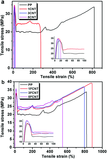 |
| | Fig. 9 Tensile stress–strain curves of PP and its composites. | |
Table 3 Summary of the mechanical test results of PP and its composites
| Sample |
Yield strength (MPa) |
Tensile strength at break (MPa) |
Young's modulus (MPa) |
Elongation at break (%) |
| PP |
32.5 ± 0.6 |
33.9 ± 0.8 |
560 ± 76 |
821 ± 85 |
| 1CNT |
34.6 ± 0.4 |
24.7 ± 0.9 |
786 ± 110 |
265 ± 20 |
| 3CNT |
34.7 ± 0.8 |
|
805 ± 132 |
25 ± 11 |
| 5CNT |
34.7 ± 0.2 |
|
975 ± 25 |
25 ± 5 |
| 1FCNT |
33.5 ± 0.8 |
39.2 ± 1.0 |
685 ± 116 |
876 ± 62 |
| 3FCNT |
35.3 ± 0.4 |
36.7 ± 1.4 |
772 ± 41 |
764 ± 54 |
| 5FCNT |
35.4 ± 1.2 |
27.5 ± 0.9 |
888 ± 106 |
541 ± 14 |
3.5 Flame retardancy
The influences of CNTs and FCNTs on the flame retardancy of PP were studied by means of cone calorimetry tests, which provides important information about fire risk such as time to ignition (ti), heat release rate (HRR), peak heat release rate (PHRR), total heat release (THR), mass loss rate (MLR), smoke production rate (SPR) and total smoke production (TSP). The results are shown in Fig. 10, 11 and Table 4. Previous studies have reported that the addition of nanofillers such as CNTs, carbon black, and carbon fibers reduce the ti value of materials.24,30,40 In this work, the incorporation of CNTs and FCNTs reduced the ti value of PP, which was in accordance with previous reports.30 Kashiwagi et al. reported that the earlier ignition time of the PP/CNT composites was ascribed to significant differences in the absorption characteristics of the external emission between the PP and PP/CNT composites.9 During the ignition process, the external emission was all absorbed near the surface of the PP/CNT composites and a narrow layer of the surface was rapidly heated, so the temperature became high enough to start ignition. On the other hand, the external emission was absorbed by PP over some depth and it took a longer time to initiate ignition.
 |
| | Fig. 10 Heat release rate (a) and total heat release (b) curves of PP and its composites. | |
 |
| | Fig. 11 Smoke production rate (a) and CO production (b) curves of PP and its composites. | |
Table 4 Combustion parameters obtained from cone calorimetry and LOI tests
| Sample |
t
i (s) |
PHRR (kW m−2) |
THR (MJ m−2) |
Average MLR (g s−1) |
Residuea (wt%) |
PSPR (m2 s−1) |
TSP (m2) |
PCOP (g s−1) |
LOI (%) |
|
Mass percentage left after finishing the tests.
|
| PP |
35 ± 4 |
1203 ± 35 |
208 ± 4 |
0.097 ± 0.004 |
0.3 ± 0.1 |
0.467 ± 0.021 |
97.2 ± 3.1 |
0.0113 ± 0.0090 |
18.2 ± 0.2 |
| 1CNT |
24 ± 2 |
945 ± 27 |
211 ± 4 |
0.083 ± 0.003 |
0.6 ± 0.1 |
0.135 ± 0.009 |
32.4 ± 0.8 |
0.0069 ± 0.0006 |
19.3 ± 0.2 |
| 1FCNT |
25 ± 2 |
775 ± 23 |
208 ± 3 |
0.066 ± 0.003 |
1.1 ± 0.1 |
0.124 ± 0.008 |
34.2 ± 0.9 |
0.0060 ± 0.0005 |
20.0 ± 0.2 |
| 3CNT |
23 ± 2 |
845 ± 24 |
208 ± 4 |
0.065 ± 0.003 |
2.0 ± 0.2 |
0.116 ± 0.007 |
31.8 ± 0.8 |
0.0067 ± 0.0006 |
21.8 ± 0.2 |
| 3FCNT |
24 ± 2 |
670 ± 22 |
200 ± 2 |
0.062 ± 0.002 |
2.9 ± 0.3 |
0.126 ± 0.008 |
37.3 ± 0.6 |
0.0064 ± 0.0005 |
22.6 ± 0.2 |
| 5CNT |
23 ± 2 |
553 ± 21 |
199 ± 3 |
0.058 ± 0.002 |
4.0 ± 0.4 |
0.101 ± 0.006 |
31.4 ± 0.6 |
0.0042 ± 0.0002 |
23.4 ± 0.2 |
| 5FCNT |
24 ± 2 |
485 ± 19 |
198 ± 2 |
0.054 ± 0.002 |
4.8 ± 0.5 |
0.086 ± 0.006 |
32.4 ± 0.7 |
0.0036 ± 0.0002 |
24.1 ± 0.2 |
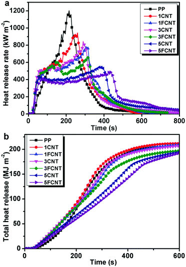
Fig. 10a shows the HRR curves of PP and its composites. For neat PP, it burnt very fast and a sharp HRR peak appeared with a PHRR as high as 1203 kW m−2. The PHRR of the PP/CNTs and PP/FCNT composites decreased with the increasing content of CNTs and FCNTs. What is more, the PHRR of the PP/FCNT composites was lower than that of the PP/CNT composites with the same content of nanofillers. The PHRR of the the 1FCNT composite was reduced by 36% compared to that of neat PP (775 kW m−2), which was lower than that of the 1CNT (945 kW m−2) and 3CNT (845 kW m−2) composites. The PHRR of the 5FCNT composite decreased to 485 kW m−2, which was lower than that of the 5CNT composite (553 kW m−2). The slope of the THR is assumed to represent the fire spread rate. As shown in Fig. 10b, the neat PP showed a fast increase in THR. The addition of 1 wt% CNTs had no effect on the THR spread rate, and the THR was slightly higher than that of neat PP. The addition of 1 wt% FCNTs and 3 wt% CNTs slowed down the THR spread rate slightly. In contrast, the addition of 3 wt% FCNTs, 5 wt% CNTs and 5 wt% FCNTs obviously decreased the THR rate. Furthermore, the 5FCNT composite showed the lowest THR spread rate.
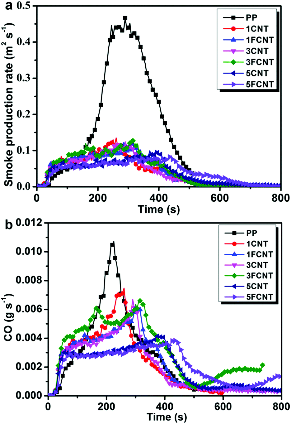
As toxic gases often act as the killer during the fire hazard, toxic gases generated during combustion are important factors concerning fire safety. Fig. 11 shows the SPR and CO production curves of PP and its composites. The addition of CNTs or FCNTs led to a great reduction of the TSP (Fig. 11a). The 5FCNT composites resulted in the smallest PSPR (0.086 m2 s−1) among all the samples. The CO production curve is shown in Fig. 11b, and the peak CO production (PCOP) of the 5FCNT composite decreased to 0.0036 g s−1, which reduced by 68% compared to that of neat PP, and was also lower than that of the 5CNT composite. To further investigate the flame retardancy of the PP composites, LOI tests were carried out. As shown in Table 4, the LOI of PP improved with the incorporation of CNTs and FCNTs, but the FCNTs were much more efficient. Compared to pure PP, the LOI increased from 18.2 to 24.1 in the case of 5FCNT. These results prove that the FCNTs are much better at improving the flame retardancy of PP than pristine CNTs. However, although FCNTs showed good flame retardancy on PP in the cone calorimetry tests, the promotion of LOI values was relatively limited, and the resultant composites still did not pass traditional UL-94 rating. Consequently, the improved flame retardancy mainly results from the formation of a network–structure protective char layer during combustion, and the positive effect of the grafted IFR is limited due to its low content. Similar phenomena were also confirmed by Bourbigot and other pioneers.41 Song et al. concluded that different rating tests often measured different parameters, and they were, in general, not comparable.30 Nevertheless, our strategy of wrapping CNTs with IFR still has importance in developing new flame retardants with high performances.
To study the mechanism for the FCNT improved flame retardancy of PP, the structure of the residual chars after cone calorimetry tests was analysed. Fig. 12 presents the photographs of the residual chars from the PP/CNT and PP/FCNT composites, and the SEM micrographs of the residual chars are shown in Fig. 13. The residual chars of the PP/CNT composites were composed of CNTs, and the surface of the residual CNTs was relatively clean (Fig. 13a). Because of the poor thermal stability of CNTs under an air atmosphere, the residual char of the 1CNT composite exhibited a large hole in the centre (Fig. 12a). With increasing loading content, the hole became smaller (Fig. 12b and c). As for the FCNT composites, because the wrapped IFR protects the CNTs from burning out during the combustion, the residual chars were composed of CNTs coated with a char layer that filled some of the space among the CNTs (Fig. 13b). The residual char of the 1FCNT composite was uniform with small cracks between the CNTs (Fig. 12d). With increasing loading content of the FCNT, the cracks became less (Fig. 12e), and finally a compact and continuous residual char without cracks was formed (Fig. 12f).
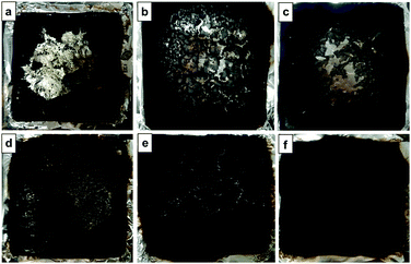 |
| | Fig. 12 Photographs of the residual chars of PP composites after cone calorimetry tests from (a) 1CNT, (b) 3CNT, (c) 5CNT, (d) 1FCNT, (e) 3FCNT and (f) 5FCNT. | |
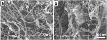 |
| | Fig. 13 FE-SEM micrographs of the residual chars after cone calorimetry tests from (a) the 3CNT composites and (b) the 3FCNT composites. | |
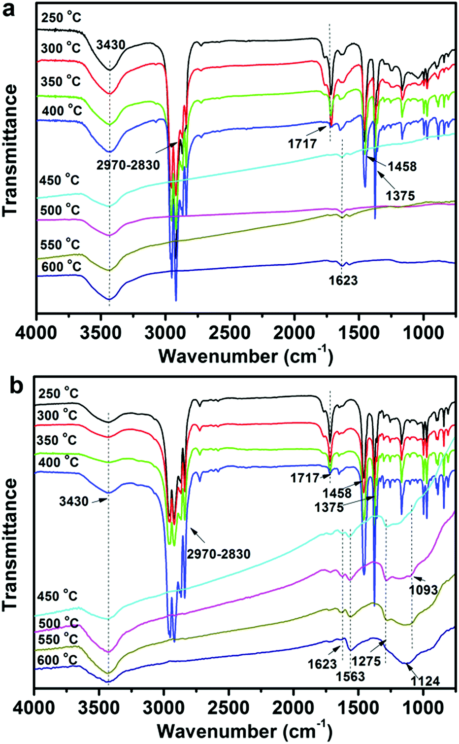
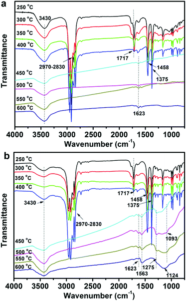
To further investigate the effect of CNTs and FCNTs on the flame retardancy of PP, the FTIR tests for condensed phase residuals from the 5CNT and 5FCNT composites were performed at different temperatures. As shown in Fig. 14, up to 450 °C, the 5FCNT and 5CNT composites showed absorption peaks at 2830–2970 cm−1, 1458 cm−1 and 1375 cm−1, which are ascribed to the characteristic absorptions of PP.42 The peak at 1717 cm−1 was assigned to the absorption of the CO bonds of PPMA and the intensity of this peak decreased with an increase of temperature. When the temperature was higher than 450 °C, PP was almost completely degraded. The 5CNT composites showed a broad peak at around 3300–3700 cm−1 (oxidation of CNTs) and a peak at 1623 cm−1 (CC). The 5FCNT composite showed more peaks at 1563 cm−1 (NO), 1275 cm−1 (PO) and 1093 cm−1 (P–O) at 500 °C,42,43 which were ascribed to the degradation of the grafted IFR. With the temperature increasing to 600 °C, the peaks at 1275 cm−1 and 1093 cm−1 disappeared, and a broad peak at 1000–1300 cm−1 appeared, which resulted from the formation of the P–O–C, P–O–P and pyrophosphate structures.42,43 The P–O–C and P–O–P structures are believed to improve the stability of the residual chars, and their cross-linked structures further facilitate the formation of the char residue through aromatization at a high temperature.43
 |
| | Fig. 14 FTIR spectra of the condensed products of (a) the 5CNT composite and (b) the 5FCNT composite at different temperatures. | |
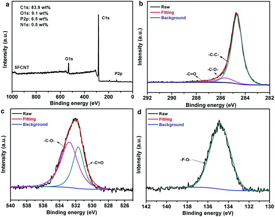
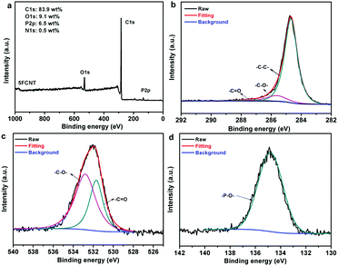
In order to further investigate the chemical structures of the condensed phase residuals, the char of the 5FCNT composite was characterized using XPS. Fig. 15a shows that the residual char of 5FCNT displayed peaks at 284.6 eV (C1s), 529.6 eV (O1s) and 134.0 eV (P2p). The disappearance of a nitrogen peak provided positive evidence that nitrogenated compounds evolved in the form of NH3 and NOx. The C1s spectrum is shown in Fig. 15b. The peaks of C1s at 248.6 eV, 285.8 eV and 286.8 eV were attributed to C–C and C–H, C–O and/or C–O–P (hydrocarbonated phosphate), and CO, respectively.44Fig. 15c shows the O1s spectrum. The peaks at 531.7 eV and 533.0 eV were assigned to double bonding O (CO and PO), and –O– in the form of C–O–C, P–O–P and P–O–C groups.44,45 The P2p spectrum of 5FCNT is presented in Fig. 15d, the peaks in between 134 eV and 135 eV were ascribed to the P–O–C, P–O–P, and/or PO3− groups in the phosphoric-rich cross-links.46 These results are well consistent with the above FTIR analysis. From the FTIR and XPS results, we conclude that the grafted IFR degrades accompanied by a release of NH3, and compact and stable residual char consisting of P–O–C, P–O–P, and CC structures formed during the combustion process.
 |
| | Fig. 15 (a) XPS spectrum, (b) high resolution C1s XPS spectrum, (c) high resolution O1s XPS spectrum and (d) high resolution P2p XPS spectrum of the residual char from the 5FCNT composite. | |
From the results obtained from calorimetry tests, photographs and FE-SEM micrographs of the residual chars, the FTIR spectra of the condensed products at different temperatures and the XPS spectrum of the residual char, we propose a possible flame retardancy mechanism for the PP/FCNT composites, as shown in Fig. 16. The flame retardant grafted onto the CNTs degrades first during combustion. On one hand, it releases inert gas to dilute the concentration of the oxygen near the surface of the material and forms the carbon layer. On the other hand, it leaves much residual char containing the P–O–P and P–O–C structures bonded onto the surface of the CNTs, which protects the CNTs and fills some of the space among the CNTs; as a result, the quality of the char is improved. The compact and continuous protective char layer, consisting of CNTs and residual char from IFR, acts as a barrier to limit heat transfer, the diffusion of the volatile thermal oxidative products, as well as oxygen from the gas phase to PP. Besides, the interfacial adhesion between the FCNTs and PP greatly improved through covalent reaction. Thus the mechanical properties of PP improved while the ductility was retained.
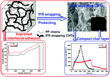 |
| | Fig. 16 Possible mechanism of the influence of FCNTs on improving the flame retardancy and mechanical properties of PP. | |
4. Conclusions
In this work, we have successfully synthesized flame retardant wrapping and PP grafted CNTs via in situ condensation polymerization and following a reaction with the PPMA. The TGA results show that the FCNT has a high char yield under both nitrogen and air atmospheres. The mechanical properties of PP/FCNT improved while the ductility was maintained, which is ascribed to the good dispersion state of the FCNTs and the strong interfacial adhesion between the FCNTs and the PP matrix. Compared to the pristine CNTs, the incorporation of FCNTs is much more efficient in enhancing the flame retardancy of PP. The wrapping IFR forms a char layer coating on the surface of the CNTs to protect the CNTs from being destroyed during combustion, so the quality of the char improved. The compact and continuous protective char layer limits the transfer of oxygen, degradation products and heat. Thus, functionalizing CNTs with the flame retardant and covalently attaching them to PP chains is a promising way to simultaneously improve the mechanical properties and flame retardancy of PP.
Acknowledgements
This work was supported by the Ministry of Science and Technology of China (2015AA033901), the National Natural Science Foundation of China (51573179, 21204079 and 51233005) and Jilin Province Science and Technology Development Program (20140203023GX).
References
- S. Iijima, Nature, 1991, 354, 56–58 CrossRef CAS.
- M.-F. Yu, O. Lourie, M. J. Dyer, K. Moloni, T. F. Kelly and R. S. Ruoff, Science, 2000, 287, 637–640 CrossRef CAS PubMed.
- M.-F. Yu, B. S. Files, S. Arepalli and R. S. Ruoff, Phys. Rev. Lett., 2000, 84, 5552–5555 CrossRef CAS PubMed.
- P. G. Collins and P. Avouris, Sci. Am., 2000, 283, 62–69 CrossRef CAS PubMed.
- J. N. Coleman, U. Khan and Y. K. Gun'ko, Adv. Mater., 2006, 68, 689–706 CrossRef.
- E. T. Thostenson, Z. F. Ren and T. W. Chou, Compos. Sci. Technol., 2001, 61, 1899–1912 CrossRef CAS.
- M. T. Byrne and Y. K. Gun'ko, Adv. Mater., 2010, 22, 1672–1688 CrossRef CAS PubMed.
- T. Kashiwagi, E. Grulke, J. Hilding, R. Harris, W. Awad and J. Douglas, Macromol. Rapid Commun., 2002, 23, 761–765 CrossRef CAS.
- T. Kashiwagi, E. Grulke, J. Hilding, K. Groth, R. Harris, K. Butler, J. Shields, S. Kharchenko and J. Douglas, Polymer, 2004, 45, 4227–4239 CrossRef CAS.
- T. Kashiwagi, F. M. Du, K. I. Winey, K. M. Groth, J. R. Shield, S. P. Bellayer, H. Kim and J. F. Douglas, Polymer, 2005, 46, 471–481 CrossRef CAS.
- T. Tang, X. C. Chen, H. Chen, X. Y. Meng, Z. W. Jiang and W. G. Bi, Chem. Mater., 2005, 17, 2799–2802 CrossRef CAS.
- T. Tang, X. C. Chen, H. Chen, X. Y. Meng, H. Chen and Y. P. Ding, Angew. Chem., Int. Ed., 2005, 44, 1517–1520 CrossRef CAS PubMed.
- G. Beyer, Fire Mater., 2002, 26, 291–293 CrossRef CAS.
- T. Kashiwagi, F. M. Du, J. F. Douglas, K. I. Winey, R. H. Harris and J. R. Shields, Nat. Mater., 2005, 4, 928–933 CrossRef CAS PubMed.
- D. Tasis, N. Tagmatarchis, A. Bianco and M. Prato, Chem. Rev., 2006, 106, 1105–1136 CrossRef CAS PubMed.
- W. Leelapornpisist, M. T. Ton-That, F. Perrin-Sarazin, K. C. Cole, J. Denault and B. Simard, J. Polym. Sci., Part B: Polym. Phys., 2005, 43, 2445–2553 CrossRef.
- H. Mahfuz, A. Adnan, V. K. Rangari and S. Jeelani, Int. J. Nanosci., 2005, 4, 55–72 CrossRef CAS.
- T. McNally, P. Pötschke, P. Halley, M. Murphy, D. Martin, S. E. J. Bell, G. P. Brennan, D. Bein, P. Lemoine and J. P. Quinn, Polymer, 2005, 46, 8222–8232 CrossRef CAS.
- T. Kashiwagi, M. F. Mu, K. Winey, B. Cipriano, S. R. Raghavan, S. Pack, M. Rafailovich, Y. Yang, E. Grulke, J. Shields, R. Harris and J. Douglas, Polymer, 2008, 49, 4358–4368 CrossRef CAS.
- P. A. Song, L. N. Liu, S. Y. Fu, Y. M. Yu, C. D. Jin, Q. Wu, Y. Zhang and Q. Li, Nanotechnology, 2013, 24, 125704 CrossRef PubMed.
- H. Y. Ma, L. F. Tong, Z. B. Xu and Z. P. Fang, Nanotechnology, 2007, 18, 375602 CrossRef.
- X. Wen, N. N. Tian, J. Gong, Q. Chen, Y. L. Qi, Z. Liu, J. Liu, Z. W. Jiang, X. C. Chen and T. Tang, Polym. Adv. Technol., 2013, 24, 971–977 CrossRef CAS.
- H. O. Yu, Z. J. Zhang, Z. Wang, Z. W. Jiang, J. Liu, L. Wang, D. Wan and T. Tang, J. Phys. Chem. C, 2010, 114, 13226–13233 CAS.
- J. Gong, R. Niu, X. Wen, H. F. Yang, J. Liu, X. C. Chen, Z. Y. Sun, E. Mijowska and T. Tang, RSC Adv., 2015, 5, 5484–5493 RSC.
- H. O. Yu, J. Liu, Z. Wang, Z. W. Jiang and T. Tang, J. Phys. Chem. C, 2009, 113, 13092–13097 CAS.
- W. Yang, B. H. Yang, H. D. Lu, L. Song and Y. Hu, Ind. Eng. Chem. Res., 2014, 53, 18489–18496 CrossRef CAS.
- T. Yu, N. Jiang and Y. Li, Compos. Sci. Technol., 2014, 104, 26–33 CrossRef CAS.
- H. Y. Ma, L. F. Tong, Z. B. Xu and Z. P. Fang, Adv. Funct. Mater., 2008, 18, 414–421 CrossRef CAS.
- H. O. Yu, J. Liu, X. Wen, Z. W. Jiang, Y. J. Wang, L. Wang, J. Zheng, S. Y. Fu and T. Tang, Polymer, 2011, 52, 4891–4898 CrossRef CAS.
- P. A. Song, L. H. Xu, Z. H. Guo, Y. Zhang and Z. P. Fang, J. Mater. Chem., 2008, 18, 5083–5091 RSC.
- B. H. Yang, C. L. Bao, L. Song, N. N. Hong, K. M. Liew and Y. Hu, Chem. Eng. J., 2014, 237, 411–420 CrossRef.
- J. Zhu, H. Peng, F. Rodriguez-Macias, J. L. Margrave, V. N. Khabashesku, A. M. Imam, K. Lozano and E. V. Barrera, Adv. Funct. Mater., 2004, 14, 643–648 CrossRef CAS.
- J. N. Coleman, M. Cadek, R. Blake, V. Nicolosi, K. P. Ryan, C. Belton, A. Fonseca, J. B. Nagy, Y. K. Gun'ko and W. J. Blau, Adv. Funct. Mater., 2004, 14, 791–798 CrossRef CAS.
- B. X. Yang, K. P. Pramoda, G. Q. Xu and S. H. Goh, Adv. Funct. Mater., 2007, 17, 2062–2069 CrossRef CAS.
- Y. W. Cao, J. C. Feng and P. Y. Wu, J. Mater. Chem., 2012, 22, 14997–15005 RSC.
- P. A. Song, Y. Shen, B. X. Du, M. Peng, L. Shen and Z. P. Fang, ACS Appl. Mater. Interfaces, 2009, 1, 452–459 CAS.
- P. A. Song, Z. P. Fang, L. F. Tong, Y. M. Jin and F. Z. Lu, J. Anal. Appl. Pyrolysis, 2008, 82, 286–291 CrossRef CAS.
- B. Yu, Y. Q. Shi, B. H. Yuan, S. L. Qiu, W. Y. Xing, W. Z. Hu, L. Song, S. M. Lo and Y. Hu, J. Mater. Chem. A, 2015, 3, 8034–8044 CAS.
- J. Gong, J. Liu, Z. W. Jiang, X. C. Chen, X. Wen, E. Mijowska and T. Tang, Appl. Catal., B, 2014, 152, 289–299 CrossRef.
- H. F. Yang, J. Gong, X. Wen, J. Xue, Q. Chen, Z. W. Jiang, N. N. Tian and T. Tang, Compos. Sci. Technol., 2015, 113, 31–37 CrossRef CAS.
- S. Bourbigot, S. Duquesne, G. Fontaine, S. Bellayer, T. Turf and F. Samyn, Mol. Cryst. Liq. Cryst., 2008, 486, 325–339 CAS.
- N. N. Tian, X. Wen, J. Gong, L. Ma, J. Xue and T. Tang, Polym. Adv. Technol., 2013, 24, 653–659 CrossRef CAS.
- Z. S. Bao, C. Deng, Y. Tian, M. J. Chen, L. Chen and Y. Z. Wang, ACS Appl. Mater. Interfaces, 2014, 6, 7363–7370 Search PubMed.
- P. Zhang, L. Song, H. D. Lu, Y. Hu, W. Y. Xing, J. X. Ni and J. Wang, Polym. Degrad. Stab., 2009, 94, 201–207 CrossRef CAS.
- C. H. Ke, J. Li, K. Y. Fang, Q. L. Zhu, Q. Yang and Y. Z. Wang, Polym. Degrad. Stab., 2010, 95, 763–770 CrossRef CAS.
- Y. H. Guan, J. Q. Huang, J. C. Yang, Z. B. Shao and Y. Z. Wang, Ind. Eng. Chem. Res., 2015, 54, 3524–3531 CrossRef CAS.
Footnote |
| † Electronic supplementary information (ESI) available. See DOI: 10.1039/c6qm00172f |
|
| This journal is © the Partner Organisations 2017 |
Click here to see how this site uses Cookies. View our privacy policy here.