Striped patterns self-assembled from rod–coil diblock copolymers on spherical substrates†
Zhou
Guan
,
Liquan
Wang
*,
Xingyu
Zhu
and
Jiaping
Lin
*
Shanghai Key Laboratory of Advanced Polymeric Materials, State Key Laboratory of Bioreactor Engineering, Key Laboratory for Ultrafine Materials of Ministry of Education, School of Materials Science and Engineering, East China University of Science and Technology, Shanghai 200237, China. E-mail: jlin@ecust.edu.cn; Tel: +86-21-6425-3370
First published on 11th October 2016
Abstract
In this work, the structures and topological defects of striped patterns self-assembled from rod–coil diblock copolymers confined on spherical substrates were examined using dissipative particle dynamics simulations. The stripes were formed by orderly packed rod blocks that were stabilized by coil blocks in solvents. Three types of disclinations with charges of +1, +1/2, and −1/2 and dislocations were observed in the striped patterns. The sum of the disclination charges was always +2, which is consistent with the Poincaré–Hopf theorem. Two categories of local defect stripe patterns were observed, namely, spiral-like and ring-like. The structures and surface densities of the defects were found to depend on various parameters, including the rigidities of the rod blocks, the radii of the spheres and the hydrophobicities of the rod blocks. The predictions were compared with our previous experimental observations and agreement was found. This work provides a method for producing striped patterns on curved substrates and can serve as a theoretical support for preparing nanoparticles with complex surface structures.
1. Introduction
Block copolymers can self-assemble into ordered nanoscale structures, such as spherical micelles and vesicles in selective solvents, and lamellar, cylindrical, and gyroidal phases in their bulk state.1–6 The introduction of geometric constraints in the systems, such as by confining block copolymers on substrates, allows for the polymers to self-assemble into novel nanostructures.7–9 Recently, the structures produced under curved constraints have attracted significant attention.10–17 By confining polymers inside curved spaces, structures with a negative curvature can be obtained. For example, Rider et al. studied the morphologies of polystyrene-b-poly(ferrocenylethylmethylsilane) (PS-b-PFS) diblock copolymers confined in silica colloidal crystals.18 Spherical colloids with onion-like lamellar phases and honeycomb-like cylindrical phases were observed. Conversely, by confining polymers outside curved spaces, nanostructures with a positive curvature can be obtained. Recently, Cai et al. discovered that poly(γ-benzyl-L-glutamate)-b-poly(ethylene glycol) (PBLG-b-PEG) rod–coil block copolymers and rigid PBLG homopolymers are able to co-assemble into virus-like superhelical rods and rings. In these structures, the block copolymers are confined on the cylindrical and toroidal substrates formed by the homopolymers, and they self-assemble into helix-like nanostructures on the templets.19,20 By mixing PBLG-b-PEG block copolymers and polystyrene (PS) homopolymers, wool-ball-like structures can been obtained. In these structures, the PS homopolymers formed spherical cores covered by PBLG-b-PEG block copolymers.21,22 The formation of wool-ball-like structures can be considered to be the result of the self-assembly of rod–coil diblock copolymers confined on the spherical substrates.In addition to their morphologies, topological defects are an important feature of the structures obtained from the self-assembly of block copolymers under confinement.23–31 It has been demonstrated that the topological defects differ under various geometrical confinements. In the case of spherical confinements, the topological defects in the cylindrical or lamellar phases on the spherical substrates have been theoretically analyzed.32–37 For the cylindrical phases, in addition to their six-fold coordinated sites, pairs of five-fold (+1 charged disclination) and seven-fold (−1 charged disclination) coordinated sites can also be produced. For the lamellar phases, there are at least four +1/2 disclination defects or two +1 disclination defects, with the sum of disclination charges always being +2. Additionally, the morphologies of these defect structures have been studied using simulation methods. For example, we studied the defect structures and ordering behaviors of the cylindrical phases of block copolymers confined on spherical substrates using the Landau–Brazovskii theory.37 It was discovered that isolated disclinations and scars are generated on the spherical substrates, and the number of excess dislocations in a scar depends linearly on the radius of the sphere. For the lamellar phases, Chantawansri et al. used a self-consistent field (SCF) theory of inhomogeneous polymers to study the nanostructures of diblock copolymers confined on a sphere.32 Defective lamellar phases containing four +1/2 disclinations or two +1 disclinations were predicted. These defects are thermodynamically stable and therefore cannot be eliminated.
However, these studies were based on the assumption that the polymer shells have uniform thicknesses or that the thicknesses are far smaller than the spherical radii. Usually, these requirements are technically difficult to achieve in experiments. In most of the reported experiments regarding this issue, coil–coil block copolymers are confined between two spherical interfaces, thus a polymer shell with the desired thickness can be obtained.38–42 Our previous experimental studies of the PBLG-b-PEG/PS binary system revealed that PBLG-b-PEG diblock copolymers can self-assemble into striped patterns on PS spheres and produce wool-ball-like structures. In this system, the PBLG blocks take a rigid α-helix form, while the PEG blocks form flexible chains. Compared with the nanostructures (e.g., lamellar and cylindrical phases) formed by the coil–coil block copolymers on spherical substrates, the preparation of wool-ball-like structures from rod–coil ones is technically facile (i.e., only one spherical interface is required and the confinement between two spherical interfaces is not necessary). Accordingly, the self-assembly mechanism that produces the wool-ball-like structures and the topological defects of the striped patterns may be different from the mechanism that produces lamellar phases formed by the coil–coil block copolymers on spherical substrates. However, experimental studies suffer from difficulties in analyzing the details of the structures. The self-assembly mechanism and topological defects of the striped patterns remain unclear.
Theoretical simulations, which are capable of providing molecular-level insights for understanding the self-assembly behavior of complex copolymers, can be used to address these challenges. Dissipative particle dynamics (DPD) simulations, which are capable of dealing with systems with larger time and length scales, are suitable for studying the self-assembly behaviors of complex copolymer systems. Using the DPD method, it has been demonstrated that a variety of parameters such as the composition, length and repulsive parameters of each segment are critical to determining the assembled structures of block copolymers.43–45 For example, we investigated the structural evolution from concentric multicompartment micelles to raspberry-like multicompartment micelles self-assembled from linear ABC triblock copolymers in selective solvents using the DPD method.46 This structural transformation can be controlled by changing either the length or the solubility of the B blocks. Additionally, the DPD method has been applied to investigate the self-assembly behaviors of block copolymers on confined substrates.47–49 For instance, Liu et al. studied the structures of diblock copolymers confined in cylindrical tubes using the DPD method.49 They found that the perpendicular and parallel lamellar phases can be alternately produced as the tube diameter is increased. In a preliminary study, we proposed a possible mechanism for the cooperative self-assembly of PBLG-b-PEG block copolymers and PS homopolymers, with the assistance of DPD simulations.22 Accordingly, it is technically feasible to use the DPD method to simulate the self-assembly behavior of block copolymers on spherical substrates.
In this study, we performed dissipative particle dynamics simulations to investigate the self-assembly behavior of rod–coil diblock copolymers on spherical substrates in selective solvents. The details of the self-assembled structures as well as the topology and surface density profile of the defects were examined. To study the self-assembled structures under different conditions, we performed the simulations on the system upon varying the rigidity of rod blocks, sphere radii, and the hydrophobicity of rod blocks. Additionally, the simulated results were compared with our previous experimental observations, and the results are shown to agree.
2. Simulation methods
In this study, we constructed a system containing one large rigid sphere, and a number of rod–coil diblock copolymers and solvents. One of the copolymers and the rigid sphere are illustrated in Fig. 1. The solvents are not shown for simplicity. The diblock copolymer consisted of a hydrophobic rod block and a hydrophilic coil block, colored green and red, respectively. The polymer segments were coarse-grained into beads connected with neighboring ones by harmonic spring bonds. The sphere was simplified to a hollow spherical substrate formed by beads, colored blue. Dissolved in solvents, the copolymers could self-assemble on the surface of the hard sphere. To guarantee a uniform arrangement of the beads forming the substrate, we adopted the maximal volume arrangement of points on the sphere proposed by Neil et al.50 The beads were set close enough to avoid the copolymer and solvents permeating into the ball.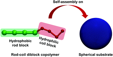 | ||
| Fig. 1 Schematic of the simulation system consisting of rod–coil block copolymers and a sphere. The rod block, coil block, and spherical substrate are colored green, red, and blue, respectively. | ||
Dissipative particle dynamics (DPD) is a mesoscopic simulation method originating from Hoogerbrugge and Koelman51,52 and developed by Robert and Patrick.53 In this method, several neighboring molecules are coarse-grained into a single particle. Newton's equations of motion are applied to calculate the trajectories of beads in the system. A modified velocity-Verlet algorithm is used for the propagation of the positions and velocities of the beads.
According to the DPD method the force Fi acting on a coarse-grained DPD bead i is the sum of the conservative force, dissipative force, and random force, represented by the following equation:
 | (1) |
The three kinds of forces on the right side of the above equation take the following forms:
 | (2) |
 | (3) |
 | (4) |
For diblock copolymers, an additional harmonic spring potential  is applied on each pair of two bonded beads i and j, and the chain stiffness potential
  is performed on three neighboring beads i, j and k in the rod blocks. In this work, the equilibrium bond distance r0 and the equilibrium value of the angle θ0 were set to be 0.7rc and π, respectively. Unless otherwise specified, the values of ks and kc were set as 100kBT/rc−2 and 100kBT, respectively (kB is the Boltzmann constant and T is temperature).46,54 All the beads that construct the spherical substrate were not included in the velocity-Verlet integration process. Consequently, the spherical substrate was fixed in the original location during the simulations. In the DPD method, there is a linear relationship between the Flory–Huggins parameter χij and the interaction parameters aij.53 A larger χij means a larger aij. For beads of the same species, the repulsive parameters aij were set to 25, and those between different types of beads were aRC = 80, aRS = 80, aRP = 25, aCS = 30, aCP = 25 and aPS = 120, as a result of the hydrophobicity of the rod blocks and spherical substrates and the hydrophilicity of the coil blocks. In these expressions, R, C, S and P denote rod blocks, coil blocks, solvents and the beads constructing the spherical substrate, respectively. The reason for setting aPS larger than the others was to guarantee that the diblock copolymers would attach to the spherical substrate without dissolving in the solvents.
The simulation boxes with periodic boundary conditions have varied sizes (l × l × l) according to the radii (R) of the spherical substrates (l = 2R + 20rc). The block copolymer beads and water beads with density ρ = 3 are filled outside the spherical substrate, leaving the inside space of the spherical substrate vacant (ρ = 0). Therefore, the number of beads including the rod–coil block copolymers and water in the system is n = (l3 − 4πR3/3) × ρ. For example, for the case of a spherical substrate with R = 10rc, the size of the simulation box is set as 40 × 40 × 40rc3, and the total number of beads outside the spherical substrate is n = (403 − 4π × 103/3) × 3 ≈ 179![[thin space (1/6-em)]](https://www.rsc.org/images/entities/char_2009.gif) 434. The amount of block copolymer beads N varies as the sphere radii changes. For simplicity, we used the surface density (N/s) of copolymers instead of N, where s denotes the surface area of the spherical substrate.
434. The amount of block copolymer beads N varies as the sphere radii changes. For simplicity, we used the surface density (N/s) of copolymers instead of N, where s denotes the surface area of the spherical substrate.
All of the simulations were performed in a simulation box with periodic boundary conditions and an NVT ensemble. The spherical substrate was placed in the center of the simulation box with polymers uniformly arranged outside the spherical substrate and dissolved in solvents, as the initial state of the simulation system. Applying velocities with a Gaussian distribution to all of the beads except those forming the spherical substrate, the DPD simulation was then run for 20![[thin space (1/6-em)]](https://www.rsc.org/images/entities/char_2009.gif) 000τ to offer enough time for the self-assembly. The time step was set to dt = 0.01τ, where τ is the time unit
000τ to offer enough time for the self-assembly. The time step was set to dt = 0.01τ, where τ is the time unit  . In the DPD simulations, m, rc, and T denote the mass, length and temperature (m = 1.0, rc = 1.0 and kBT = 1.0).53 Under each parameter condition, the simulation was performed 10 times with different random number seeds, and the final quantitative results were averaged from the 10 simulations.
3. Results and discussion
In this work, we chose the surface density of copolymers N/s = 1.4rc−2, and a model of R4C4 rod–coil block copolymers (contains 4 rod beads and 4 coil beads) was adopted. These are considered to be the optimal conditions for the formation of the ordered structures on a spherical substrate. The structures of simulated striped patterns from rod–coil diblock copolymers were examined. Additionally, topological defects were identified in the morphologies. To reveal the mechanism of defect formation, we examined the topology and dynamics of the defect formation. Then, we performed simulations by varying three important parameters, which were the rigidities of the rod blocks, the radii of the spherical substrates, and the hydrophobicities of the rod blocks. The surface densities of all types of defects were statistically examined under various conditions. Finally, the results were discussed and compared with our previous experimental observations.3.1 Defect striped patterns on spherical substrates
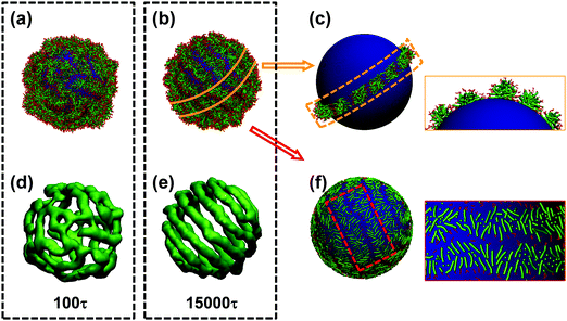
In this subsection, the formation of striped patterns and the topological defects are investigated. Fig. 2 shows the self-assembly details of the structures with sphere radius R = 14rc. The morphology of the structure and the volumetric map of the rod blocks at 100τ and 15![[thin space (1/6-em)]](https://www.rsc.org/images/entities/char_2009.gif) 000τ are presented in Fig. 2(a), (d) and (b), (e), respectively. When the simulation begins, the rod–coil block copolymers start aggregating on the spherical substrate and discontinuous stripes are gradually formed at the early stages of the simulation, as shown in Fig. 2(a) and (d). As the simulation proceeds, the stripes become continuous, and regular striped patterns can be obtained when the structure becomes stable, as shown in Fig. 2(b) and (e). The spheres with stripe-patterned surfaces look like wool balls. The stripe widths and pitches (a pitch denotes the distance between two neighboring parallel stripes) are almost uniform. Statistical analysis shows that the average stripe width and pattern pitch are 5.0rc and 6.7rc, respectively, which are independent of the radius of the spheres (ESI,† Section S1). Fig. 2(c) and (f) present details of the structures, which illustrate the packing manner of the copolymers. As shown in Fig. 2(c), the inner core and outer layer of the stripes consisted of rod blocks and coil blocks, respectively. The rod blocks are oriented perpendicular to the stripe axis, as illustrated in Fig. 2(f), similar to the structure of smectic liquid crystals.
000τ are presented in Fig. 2(a), (d) and (b), (e), respectively. When the simulation begins, the rod–coil block copolymers start aggregating on the spherical substrate and discontinuous stripes are gradually formed at the early stages of the simulation, as shown in Fig. 2(a) and (d). As the simulation proceeds, the stripes become continuous, and regular striped patterns can be obtained when the structure becomes stable, as shown in Fig. 2(b) and (e). The spheres with stripe-patterned surfaces look like wool balls. The stripe widths and pitches (a pitch denotes the distance between two neighboring parallel stripes) are almost uniform. Statistical analysis shows that the average stripe width and pattern pitch are 5.0rc and 6.7rc, respectively, which are independent of the radius of the spheres (ESI,† Section S1). Fig. 2(c) and (f) present details of the structures, which illustrate the packing manner of the copolymers. As shown in Fig. 2(c), the inner core and outer layer of the stripes consisted of rod blocks and coil blocks, respectively. The rod blocks are oriented perpendicular to the stripe axis, as illustrated in Fig. 2(f), similar to the structure of smectic liquid crystals.
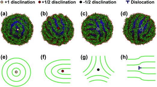
The simulated morphologies demonstrate that the stripes are discontinuous or occasionally rotated. Topological defects can be found around these locations. Fig. 3 shows the morphologies and schematics of defect structures in the striped patterns on spherical substrates from different visual angles. The defects can be classified into four types according to the morphologies of the local stripes. The four types of topological defects are +1 charged disclination (Fig. 3(a) and (e)), where the stripes are rotated 360° around the disclination core; +1/2 charged disclination (Fig. 3(b) and (f)), where the stripes are rotated 180° around the disclination core; −1/2 charged disclination (Fig. 3(c) and (g)), where three stripes are rotated 120° and oriented into three different directions; and dislocations (Fig. 3(d) and (h)), where one of the parallel stripes is abruptly truncated and a free end is produced.
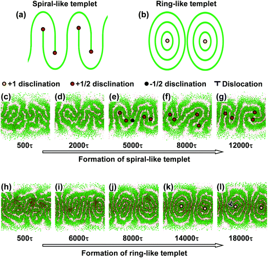
At early steps during the self-assembly, all four types of defects were found in the striped patterns. As the self-assembly proceeded, the patterns became ordered and the number of defects gradually decreased. Finally, when the systems reached equilibrium, well-ordered striped patterns were obtained, while some defects remained in these patterns until the end of the simulation. By comparing all of the striped patterns with defects in the equilibrium states, we found two categories of the stripe-patterned templet, according to the numbers and types of the remaining defects. They are spiral-like and ring-like templets, delineated by either four +1/2 charged disclinations or two +1 charged disclinations remaining in the striped patterns, respectively. These two patterns are shown in Fig. 4(a) and (b). Moreover, we provide two representative evolutions of the morphologies to illustrate how these two stripe-patterned templets are formed, as shown in Fig. 4(c–l). Fig. 4(c–g), corresponding to R = 10rc, shows the morphologies of the formation of the spiral-like templet. The striped patterns formed at the early steps have high surface densities of the four types of defects, as shown in Fig. 4(c). As the simulation proceeds, the defects are gradually eliminated, with those remaining having four +1/2 charged disclinations, forming the templet of a spiral-like striped pattern. As shown in Fig. 4(e–g), two pairs of +1/2 charged disclinations reside at the north and south poles of the spherical substrate. Fig. 4(h–l), corresponding to R = 14rc, shows the morphologies of the formation of ring-like templets. Similar to the case of spiral favored evolutions, the morphologies originate from disordered striped patterns with high surface densities of defects, and the defects are reduced, which can be seen in Fig. 4(h–j). However, the structures have the tendency to transform to striped patterns with two +1 charged disclinations on the north and south poles of the spherical substrate, as shown in Fig. 4(k) and (l). Upon varying sphere radii from 7rc to 14rc, the two evolutions can be alternatively observed.
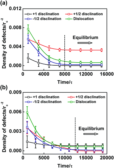
We also calculated the surface densities of the four types of topological defects to quantitatively study the defects during the spiral and ring favored evolutions. The results are shown in Fig. 5. Fig. 5(a) and (b) show the case of spiral and ring favored evolutions, corresponding to the morphologies of Fig. 4(c–g) and (h–l), respectively. As seen in Fig. 5, for both cases, before the time when the structures reach equilibrium (indicated by the dashed line in Fig. 5), the surface densities of all four types of defects decrease rapidly. However, the evolutionary tendency of the +1/2 and +1 charged disclinations are different from each other. In the case of Fig. 5(a), the surface densities of the +1/2 charged disclinations remain larger than those of the +1 ones. This corresponds to the formation of a striped pattern with four +1/2 charged disclinations and without +1 ones. Consequently, a spiral-like templet is obtained. Meanwhile, in the case of Fig. 5(b), although the surface density of +1/2 disclinations is larger than that of +1 ones before the structures reach equilibrium, the decrease of the surface density of +1/2 disclinations is faster than that of +1 ones, leading to a higher surface density of +1 disclination in the equilibrium state. This indicates the formation of a striped pattern with two +1 charged disclinations remaining and all of the +1/2 ones eliminated. In this case, the striped pattern is a ring-like templet.
The striped patterns are thermodynamically stable and the defects are unavoidable. The surface densities of defects remain unchanged and cannot be reduced to 0rc−2 at the equilibrium state. Constrained by the Euler characteristic χE = 2 of the spherical substrate, +1/2 and +1 charge disclinations are produced with the sum of the disclination charges always equal to +2, which can never be completely eliminated.32–37 The −1/2 charged disclinations are produced to reduce the sum of disclination charges to +2. This phenomenon is unlike that on flat substrates, where the disclinations are topologically dispensable.24–27 On the other hand, due to the conformational entropy of polymer chains, dislocations are produced to minimize the local free energy.28 For example, there is a dislocation in the ring-like templet, shown in Fig. 4(l), which cannot be eliminated. Moreover, in Fig. 5, the surface density of the dislocations stays above 0rc−2 at equilibrium states. We also studied the effect of polymer length on the appearance and morphology of the topological defects in the striped patterns. The number of beads on the rod block was varied from 4 to 7, and the coil length was varied from 3 to 10. It was found that the nature of the defects remains unchanged. In addition, by increasing the polymer density (N/s), we found that the striped patterns remained on the spherical substrates. But the stripe widths were increased and the copolymer shells became thicker.
3.2 Effect of the rigidity of the rod blocks
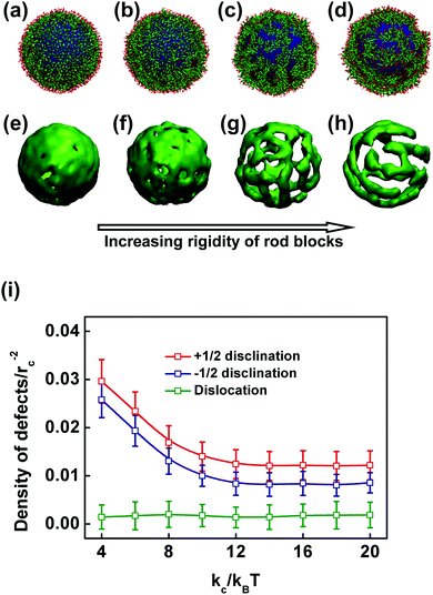
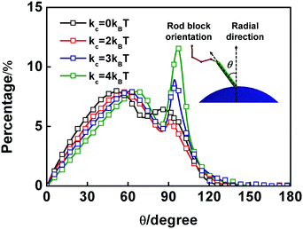
The existence of rod segments in the block copolymers may result in unique self-assembly features. To reveal the role played by rod blocks in the self-assembly of rod–coil copolymers on spherical substrates, we examined the effect of the rigidity of the rod blocks (kc) in this subsection. Fig. 6 presents the simulated structures for various rigidities of rod blocks and the surface densities of defects as functions of kc. Fig. 6(a–d) and (e–h) show the morphologies of rod–coil block copolymers self-assembled on the spherical substrates and volumetric map images of rod blocks, respectively, for kc = 0, 2, 4, and 20kBT. When the rigidity of the rod blocks is small (kc < 4kBT), the copolymers cover the sphere substrate homogeneously, with rod and coil blocks forming the inside and outside layers, respectively. As the rod blocks become more rigid, the copolymers tend to become phase-separated on the spherical substrate. When the rigidity increases further (kc ≥ 4kBT), separated domains are transformed into striped patterns. Topological defects of the striped patterns can be observed in the morphologies for the case of kc ≥ 4kBT. As the rigidity of the rod blocks increases, the striped patterns become more ordered, and the surface density of the defects decreases. Fig. 6(i) shows the surface densities of the three types of defects as functions of kc. One +1 charged disclination is counted as two +1/2 ones because they are topologically identical.55 Because there are no striped patterns or defects for the case of kc < 4kBT, only the surface densities of the defects for the case of kc ≥ 4kBT are shown. As kc increases, the surface densities of +1/2 and −1/2 disclinations decrease for kc < 10kBT and almost remain unchanged for kc ≥ 10kBT. Meanwhile, the surface density of the dislocations is independent of kc. The high densities of disclinations for small kc values are attributed to the unordered packing of the rod blocks, which results in rotated stripes (disclinations are produced by rotated stripes). As kc increases, the packing of the rod blocks becomes ordered. The stripes are straightened, and the densities of disclinations decrease as a consequence. However, the continuity of stripes remains unchanged when kc is increased. In this case, the numbers of stripe free ends are almost invariant and the surface density of dislocations is independent of kc.The primary reason for the transformation from homogeneously packed polymer layers to striped patterns is the redirection of rod block orientation vectors as the chain stiffness increases. To verify this assumption, we calculated the probability distribution profile of the angle θ between rod block orientations and the radial direction. The results are presented in Fig. 7. The schematic illustration of the angle θ is shown in the inset of Fig. 7. The horizontal and vertical axes in Fig. 7 indicate values of θ ranging from 0° to 180° and the percentage of the corresponding angle θ, respectively. When the rod blocks have low chain stiffnesses (kc = 0kBT), the probability distribution curve has two peaks at approximately 50° and 90°. As the chain stiffness increases, both peaks move to the right, as seen in Fig. 7, where both peaks move to larger values of θ. In addition, the intensity of the second peak increases sharply as the chain stiffness increases. As kc increases to 4kBT, a peak located at 97° with a probability of 14% is shown. These results indicate that as the chain rigidity increases, the rod blocks have a tendency to reorient perpendicular to the local normal vectors and an increasing number of rod blocks orient themselves parallel to the tangent plane.
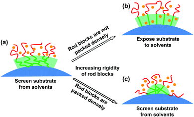
The enhanced capability of the formation of striped patterns as the rigidity of the rod blocks increases is enthalpically favorable. The schematic of this transformation mechanism is illustrated in Fig. 8. As shown in Fig. 8(a), when the rod blocks have weaker chain stiffnesses, they are packed densely on the spherical substrate, with coil blocks forming the outer layer. The solvents do not make contact with the spherical substrate, and the system has low free energy. As the chain stiffness increases, the rod blocks stretch. If they were to continue aligning along the radial directions, a loose packing manner would be obtained. Thus, the spherical substrates would be exposed to the solvents, as shown in Fig. 8(b). Because the beads constructing the spherical substrate (P) are strongly hydrophobic (aPS = 120), the interaction enthalpy would increase in this situation. Although the solvents and polymers have higher translational entropy, the free energy of the system would increase due to its increased free space. As a result, the polymers reorient, as shown in Fig. 8(c). Some of the rod blocks lie down and are packed densely, clinging to the substrate. The solvents do not make contact with the substrate any more, leading to reduced enthalpy. Although the solvents and polymers have lower translational entropy, the free energy in the system is reduced. Consequently, the transformation from a homogenous polymer shell to striped patterns as the rigidity of the rod blocks increases is enthalpically favorable.
3.3 Effect of spherical substrate radii
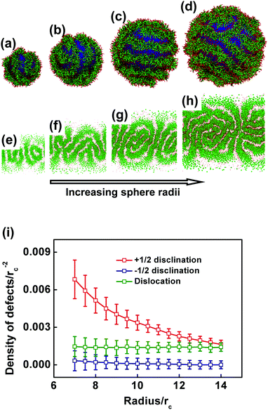
In this subsection, we studied the effect of the spherical substrate radius because it is an important geometrical parameter in determining the self-assembled structures. In the simulations, the amount of copolymers is varied synchronously upon increasing the spherical substrate radius to keep the surface density constant at N/s = 1.4rc−2. This variation guarantees constant thickness of the polymer layer under various sphere radii. Here, we increased the spherical substrate radius gradually from 7rc to 14rc by a step of 0.1rc, so that the precise statistical profile of the defects can be captured.The morphologies of the simulated structures under spherical radii R = 7, 9, 11, and 13rc are shown in Fig. 9(a–d), respectively. We also present the Miller cylindrical projections of the structures in Fig. 9(e–h),56 so that the full morphologies of the self-assembled structures on the spherical substrates can be viewed. As the sphere radius increases, more stripes are produced on the substrate, while the stripe width and pattern pitch are almost unchanged (ESI,† Section S1). Defects can be found in the striped patterns at any spherical radius. Among the simulated morphologies, we observed the spiral-like and ring-like striped patterns alternately with varying sphere radii. The sum of disclination charge is always +2, but the amount of defects varies. To determine the quantitative relationship between the topological defects and the sphere radius, we examined the surface densities of the three kinds of defects (dislocations and +1/2, −1/2 charged disclinations) as functions of the sphere radius. The results are presented in Fig. 9(i). Again, one +1 charged disclination is counted as two +1/2 ones. The surface density of dislocations is almost constant at 0.0012rc−2, however that of the +1/2 and −1/2 disclinations decreases gradually.
The decrease in the surface density of the disclinations and the consistency of the density of dislocations as the sphere radius increases are attributed to the geometrical constraints of the spherical substrate and the fixed surface density of the polymers, respectively. Defect-minimized striped patterns (having only four +1/2 or two +1 charged disclinations) are produced regardless of the spherical substrate radii. Therefore, the surface densities of the disclinations decrease as the sphere radii increase. However, as the surface density of the polymers is fixed, the probability of the production of dislocations is almost constant. The surface density of the dislocations for various spherical substrate radii is consequently invariant.
In addition, we can predict the defect densities when the radii of spherical substrates are increased to infinite (R → ∞), by means of extrapolation. As shown in Fig. 9(i), because the surface density of the dislocations almost remains unchanged at about 0.0012rc−2 upon increasing the radius of the spherical substrate, it can be inferred that the dislocation density maintains this value with further increasing radius, even to infinite. The invariableness of the surface density of dislocation is due to the fixed surface density of the polymers, because the dislocation density is proportional to the polymer density.61 While for the surface densities of the +1/2 and −1/2 charged disclinations, they would continually decrease with increasing radius. When the radius reaches to infinite (corresponding to a flat surface), the density of the disclinations would be decreased to almost zero. According to the Poincaré–Hopf theorem, the disclinations with the sum of charges equal to +2 (the Euler characteristic of a sphere χE = 2) should be maintained on a spherical substrate. Consequently, upon increasing the radius to infinite, the disclination densities would be decreased to extremely close to zero.
3.4 Effect of rod block hydrophobicity aRS
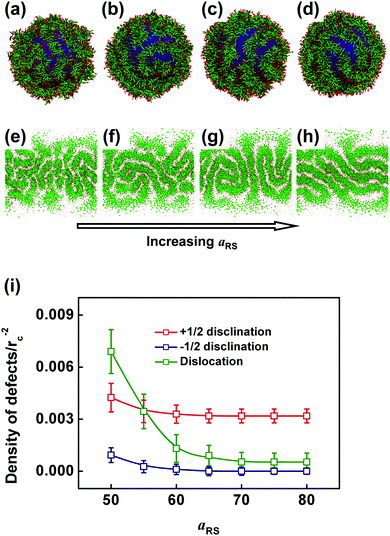
In addition to the rigidity of the rod blocks and spherical substrate radii, we further examined the effect of rod block hydrophobicity (aRS) on the self-assembled structures. In the simulations, the value of aRS was increased by a step of 5 gradually from 50 to 80 with all the other parameters kept constant.First, we studied the simulated structures at various rod block hydrophobicity values (aRS). The morphologies and Miller cylindrical projections under aRS = 50, 60, 70, and 80 are presented in Fig. 10(a–d) and (e–h), respectively. Striped patterns on spherical substrates can be observed in each structure. All four types of topological defects (dislocations and +1, +1/2, −1/2 charged disclinations) can be found in the morphologies. At the smallest value of aRS (aRS = 50), the structure is the most disordered one among all the structures with different aRS, and it has the highest surface density of topological defects as shown in Fig. 10(a) and (e). As aRS increases, the structures become ordered, and the surface density of the topological defects in the morphologies decreases. When the value of aRS reaches 80, the structure is well ordered with the lowest surface density of defects, as shown in Fig. 10(d) and (h). The surface densities of +1/2, −1/2 charged disclinations and dislocations as functions of aRS are shown in Fig. 10(i). Again, one +1 charged disclination is counted as two +1/2 ones. As aRS increases, the surface densities of all the three types of defects decrease when aRS < 65 and are nearly constant when aRS ≥ 65. However, the surface density of the dislocations decreases much more significantly than those of the +1/2 and −1/2 charged disclinations when aRS < 65.
The massive production of defects at low aRS and the reduction of defects as aRS increases are both enthalpically favorable. For the case of a smaller value of aRS, the rod blocks have weak hydrophobicities. As a result, they can be exposed to solvents to some extent. The rod blocks are packed loosely, leading to the production of discontinuous stripes and a large number of topological defects. Although disordered packing leads to an increase of entropy, the system maintains this structure with minimized free energy, due to a favor of lower enthalpy. As the value of aRS increases gradually, the rod blocks become more hydrophobic. In this case, they would be packed densely without exposure to solvents, minimizing the interaction enthalpy. The stripes are more continuous, and the surface density of the topological defects consequently decreases. Although this could decrease the entropy due to the ordered alignment of the rod blocks, the free energy of the system is minimized because of the enthalpy contribution. The above analysis indicates that the interplay of the entropy and the entropy of the system determine the final structures.
3.5 Comparison with experimental observations
In a previous study,21 we reported an investigation of the cooperative self-assembly of a mixture containing poly(γ-benzyl-L-glutamate)-b-poly(ethylene glycol) (PBLG-b-PEG) block copolymers and polystyrene (PS) homopolymers. When adding selective solvents (water), a two-step self-assembly occurs. The homopolymers first aggregate into spheres due to the low critical water content of PS (CWC = 9.1 vol%). As PBLG-b-PEG has a higher CWC (14.4 vol%), the block copolymers remain dissolved in solution. As water is added, the block copolymers start self-assembling on the substrates of the PS-formed spheres, and wool-ball-like structures are finally observed. The PBLG blocks take a rigid α-helix form, while the PEG blocks are flexible chains. The PBLG and PEG blocks can correspond to the rod and coil blocks in the simulations in this study. The spherical cores formed by the PS homopolymers can be simplified to rigid spherical substrates constructed by hydrophobic beads in the simulations. By performing DPD simulations of the self-assembly behaviors of the rod–coil diblock copolymers on spherical substrates in selective solvents, the wool-ball-like structures observed in the experiments have been reproduced well (i.e., the striped patterns on spherical substrates). In our previous experiments, in addition to observing the wool-ball-like structures, we have examined the effects of the self-assembling temperature on the aggregate structures. The SEM images are represented in Fig. 11(a–c). The results show that the PBLG141-b-PEG112/PS664 binary system (the subscripts denote the polymerization degree (DP) for each segment) self-assembles into spheres with smooth surfaces at 5 °C. When the temperature is increased to 20 °C, spheres with stripe-patterned surfaces were observed. When the temperature is further increased to 40 °C, the striped patterns become clearer. The experiments indicated that the self-assembling temperature has a prominent influence on the aggregate structures.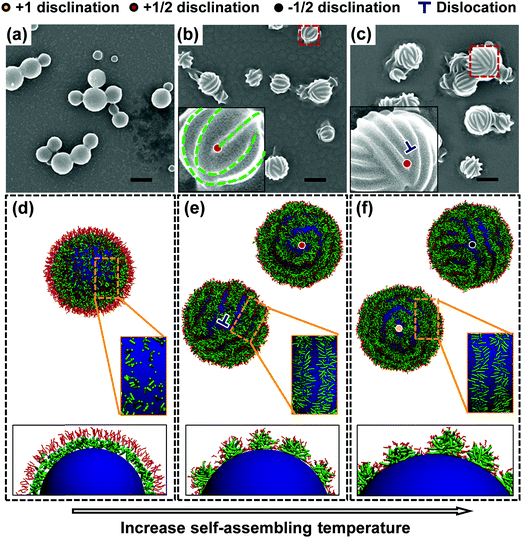 | ||
| Fig. 11 (a–c) SEM images of spheres prepared from the PBLG141-b-PEG112/PS664 mixtures at various temperatures: (a) 5 °C, (b) 20 °C, and (c) 40 °C. Scale bars: 500 nm. The insets in (b) and (c) are the enlarged SEM images of one sphere. Squares with red dashed lines in (b) and (c) indicate the spheres magnified in the insets. (d–f) Morphologies of simulated structures for rod–coil diblock copolymers self-assembled on spherical substrates with various aCS: (d) aCS = 20, (e) aCS = 30, and (f) aCS = 40. The structural details are illustrated in the insets of (d–f). Topological defects are marked in both the insets of the SEM images and simulated morphologies. A part of the spiral-like templet is indicated by the green dashed lines in the inset of (b). The SEM images were reproduced with permission from ref. 21. Copyright 2013, Wiley-VCH. | ||
After a careful examination of the striped patterns, we found that the defects exist. Such a phenomenon was not mentioned in our previous report. From the SEM images, dislocations and +1/2 charged disclinations can be seen, as shown in the insets of Fig. 11(b) and (c). The defects can be found in the striped patterns on every sphere in varying types and amounts. Here, we carried out a simulation to reproduce the observed phenomenon. The hydrophilicity of PEG can be reduced at a higher temperature (Flory–Huggins parameter χPEG–water is increased with increasing temperature). According to the formula of repulsive parameters aij = aii + 3.27χij,53 an increase of aCS between the coil blocks and solvents in the simulation corresponds to the increase of temperature in the experiments.21,57,58 In this study, aCS is varied from 20 to 40 (aCS = 20 denotes negative χPEG–water and a strong hydrophilicity of PEG, while aCS = 40 represents a weak hydrophilicity of PEG), corresponding to the temperature varying from 5 °C to 40 °C in the experiments. In addition, a model of the coarse-grained diblock copolymer was built such that the relative length of the blocks matches the experimental data.59,60 In the present simulations, the model of R4C4 rod–coil block copolymers (containing 4 rod beads and 4 coil beads) was adopted, which can capture the essential features of the PBLG141-b-PEG112 block copolymers in the experiments (ESI,† Section S2).
After setting the parameters, we performed the simulations. The results are shown in Fig. 11(d–f). As can be seen, as aCS increases, the structure on the spherical substrate is transformed from a smooth monolayer to striped patterns. When aCS is small (aCS = 20), the coil blocks are well dissolved, tending to stretch significantly in the radial orientation, and the rod blocks of the copolymers cannot align in an orderly manner. Consequently, no striped patterns are formed. As aCS increases, which corresponds to increasing of the self-assembling temperature, the block copolymers are almost uniformly arranged on the spherical substrate and stripes are formed. When aCS = 40, these striped patterns remain on the spherical substrate. We can find a good qualitative agreement between the simulations and experiments. In addition to reproducing the experimental observations, the present simulations provide information about the self-assembly behavior and packing details of rod–coil diblock polymers on spherical substrates. As shown in the insets of Fig. 11(e) and (f), the rod blocks aggregate into stripes covered by coil blocks, and they are oriented perpendicular to the stripe axis, resembling the structure of smectic liquid crystals.
The simulations also provide comprehensive information about the topological defects in the self-assembled striped patterns. Four types of defects were observed in the striped patterns, as shown in Fig. 11(e) and (f), which are dislocations and +1, +1/2, and −1/2 charged disclinations. Compared with our previous experimental results, two additional types of defects (+1 and −1/2 charged disclinations) were observed in the simulations. In an additional experiment, we found that −1/2 charged disclinations can be produced in the striped patterns (ESI,† Section S2). The spiral-like templet of the striped pattern predicted in the simulation is also found in the experiments. Although the SEM images cannot provide the whole view of these spheres, it can be inferred that there are four +1/2 charged disclinations in the enlarged image of the sphere shown in Fig. 11(b), corresponding to the spiral-like templet of the striped patterns. A part of the spiral-like templet can be seen on the sphere, which is indicated by the green dashed lines in the inset of Fig. 11(b). However, the +1 charged disclinations have not yet been found. As a consequence, the ring-like templet (delineated by two +1 charged disclinations) cannot be found. This may be due to a higher energy barrier for the formation of +1 charged disclinations. Chantawansri et al. have demonstrated a greater difficulty in obtaining +1 charged disclinations than obtaining other types of defects using a self-consistent field theory.32 Nevertheless, the present simulations revealed the detailed topology and formation mechanism of defects in the striped patterns and predicted the possibility of the formation of +1 charged disclinations.
The self-assembly of polymers on curved substrates provides a promising strategy for the generation of complex aggregates with controlled structures. The self-assemblies with high dimensional confinements exhibit prominent advantages over those with low dimensional confinements in producing controllable and multi-functional properties and facilitating their applications such as in nanoreactors. In this work, we reported the self-assembly of rod–coil block copolymers confined on spherical substrates. Striped patterns with unavoidable topological defects were predicted on the spherical substrates. Compared with the nanostructures formed by coil–coil block copolymers on spherical substrates, where the shell thicknesses are restricted32–37 or an additional spherical interface is required outside the polymer shell,38–42 the striped patterns self-assembled from rod–coil diblock copolymers in this study are technically easy to obtain experimentally (i.e., only one spherical interface is required and an additional spherical interface outside the polymer shell is not necessary). For the spheres with stripe-patterned surfaces, due to the rigidity and hydrophobicity of the rod blocks, the polymers can spontaneously cover the spherical substrates in an ordered packing manner, aligning into stripes. Hydrophilic coil blocks form the outer layer of the stripes, covering the rod blocks and stabilizing the structures. This hydrophilic shell on the spheres avoids further aggregation of polymers onto the spheres and plays the role of soft confinement outside the striped patterns. The thickness of the polymer shell is therefore constrained. This unique packing of polymers may be the primary reason for the minimal experimental requirements for obtaining wool-ball-like structures.
In addition to providing a promising strategy for the production of complex aggregates with controlled structures, the novel structures obtained in this study are reminiscent of virus particles containing DNA/RNA cores covered by proteins. For example, Poxviridae (a virus family), with its substrates covered by filament proteins, has a wool-ball-like appearance. This study on the formation mechanism of hierarchical assemblies can be of practical significance for the construction of complicated biological analogues such as a model virus and the subsequent investigation of its physiological behavior, such as cell penetration.
4. Conclusion
We employed the dissipative particle dynamics method to study the structures self-assembled from diblock copolymers on spherical substrates in solution. By introducing rigidity in the hydrophobic blocks, striped patterns can be produced on the spherical substrate. The stripes are formed by orderly packed rod blocks, stabilized by coil blocks in solvents. Four types of defects are observed in the striped patterns, which are +1, +1/2, −1/2 charged disclinations and dislocations. The sum of disclination charges is always +2, consistent with the Poincaré–Hopf theorem. Two categories of stripe-patterned templet defects, spiral-like and ring-like, symbolized by the appearance of four +1/2 and two +1 charged disclinations, respectively, are predicted in the self-assembled structures. The densities of disclinations and dislocations depend in different ways on the rigidity of the rod block, the spherical substrate radius and the hydrophobicity of the rod blocks. The self-assembly mechanism underlying the striped patterns is different from that underlying the nanostructures formed by coil–coil block copolymers on spherical substrates. In addition, the simulations successfully reproduced the wool-ball-like structures self-assembled from poly(γ-benzyl-L-glutamate)-b-poly(ethylene glycol) (PBLG-b-PEG) diblock copolymers and polystyrene (PS) homopolymers in selective solutions (water). The results may provide useful information on the preparation of nanoparticles with complex surface nanostructures.Acknowledgements
This work was supported by the National Natural Science Foundation of China (51303055, 21234002, and 21474029) and the National Basic Research Program of China (2012CB933600). Support from Projects of Shanghai municipality (13JC1402000) is also appreciated.References
- J. Y. Park, M. Liu, J. Mays, M. Dadmun and R. Advincula, Soft Matter, 2008, 4, 747–749 Search PubMed.
- D.-W. Sun, Z.-Y. Sun, H.-F. Li and L.-J. An, Polymer, 2009, 50, 4270–4280 CrossRef CAS.
- J. Wang, K. Guo, L. An, M. Müller and Z.-G. Wang, Macromolecules, 2010, 43, 2037–2041 CrossRef CAS.
- Y. Zhuang, L. Wang and J. Lin, Acta Polym. Sin., 2011, 11, 1320–1328 CrossRef.
- Y. Xing, S. Lin, J. Lin and X. He, Chin. J. Polym. Sci., 2013, 31, 833–840 CrossRef CAS.
- J. Huang, X. Huang, W. Hu and W. Lou, J. Polym. Sci., Part A: Polym. Chem., 1996, 34, 1317–1324 CrossRef CAS.
- H. P. Huinink, M. A. van Dijk, J. C. M. Brokken-Zijp and G. J. A. Sevink, Macromolecules, 2001, 34, 5325–5330 CrossRef CAS.
- A. Knoll, A. Horvat, K. S. Lyakhova, G. Krausch, G. J. A. Sevink, A. V. Zvelindovsky and R. Magerle, Phys. Rev. Lett., 2002, 89, 035501 CrossRef CAS PubMed.
- X. Ye, B. J. Edwards and B. Khomami, Macromolecules, 2010, 43, 9594–9597 CrossRef CAS.
- B. Yu, B. Li, Q. Jin, D. Ding and A.-C. Shi, Soft Matter, 2011, 7, 10227–10240 RSC.
- J. G. E. M. Fraaije and G. J. A. Sevink, Macromolecules, 2003, 36, 7891–7893 CrossRef CAS.
- H. Xiang, K. Shin, T. Kim, S. Moon, T. J. McCarthy and T. P. Russell, J. Polym. Sci., Part B: Polym. Phys., 2005, 43, 3377–3383 CrossRef CAS.
- W. Li, R. A. Wickham and R. A. Garbary, Macromolecules, 2006, 39, 806–811 CrossRef CAS.
- P. Chen, X. He and H. Liang, J. Chem. Phys., 2006, 124, 104906 CrossRef PubMed.
- C. R. Stewart-Sloan and E. L. Thomas, Eur. Polym. J., 2011, 47, 630–646 CrossRef CAS.
- Y. Wu, G. Cheng, K. Katsov, S. W. Sides, J. Wang, J. Tang, G. H. Fredrickson, M. Moskovits and G. D. Stucky, Nat. Mater., 2004, 3, 816–822 CrossRef CAS PubMed.
- B. Yu, P. Sun, T. Chen, Q. Jin, D. Ding, B. Li and A.-C. Shi, Phys. Rev. Lett., 2006, 96, 138306 CrossRef PubMed.
- D. A. Rider, J. I. L. Chen, J.-C. Eloi, A. C. Arsenault, T. P. Russell, G. A. Ozin and I. Manners, Macromolecules, 2008, 41, 2250–2259 CrossRef CAS.
- C. Cai, J. Lin, T. Chen, X.-S. Wang and S. Lin, Chem. Commun., 2009, 2709–2711 RSC.
- C. Cai, L. Wang and J. Lin, Chem. Commun., 2011, 47, 11189–11203 RSC.
- C. Cai, Y. Li, J. Lin, L. Wang, S. Lin, X.-S. Wang and T. Jiang, Angew. Chem., Int. Ed., 2013, 52, 7732–7736 CrossRef CAS PubMed.
- X. Zhu, Z. Guan, J. Lin and C. Cai, Sci. Rep., 2016, 6, 29796 CrossRef PubMed.
- W. Li and M. Müller, Annu. Rev. Chem. Biomol. Eng., 2015, 6, 187–216 CrossRef CAS PubMed.
- B. Vorselaars, J. U. Kim, T. L. Chantawansri, G. H. Fredrickson and M. W. Matsen, Soft Matter, 2011, 7, 5128–5137 RSC.
- C. Harrison, D. H. Adamson, Z. Cheng, J. M. Sebastian, S. Sethuraman, D. A. Huse, R. A. Register and P. M. Chaikin, Science, 2000, 290, 1558–1560 CrossRef CAS PubMed.
- D. A. Vega, L. R. Gomez, A. D. Pezzutti, F. Pardo, P. M. Chaikin and R. A. Register, Soft Matter, 2013, 9, 9385–9391 RSC.
- M. R. Hammond and E. J. Kramer, Macromolecules, 2006, 39, 1538–1544 CrossRef CAS.
- S. O. Kim, H. H. Solak, M. P. Stoykovich, N. J. Ferrier, J. J. de Pablo and P. F. Nealey, Nature, 2003, 424, 411–414 CrossRef CAS PubMed.
- T. Higuchi, K. Motoyoshi, H. Sugimori, H. Jinnai, H. Yabu and M. Shimomura, Soft Matter, 2012, 8, 3791–3797 RSC.
- B. Yu, B. Li, Q. Jin, D. Ding and A.-C. Shi, Macromolecules, 2007, 40, 9133–9142 CrossRef CAS.
- L. Zhang, L. Wang and J. Lin, ACS Macro Lett., 2014, 3, 712–716 CrossRef CAS.
- T. L. Chantawansri, A. W. Bosse, A. Hexemer, H. D. Ceniceros, C. J. García-Cervera, E. J. Kramer and G. H. Fredrickson, Phys. Rev. E: Stat., Nonlinear, Soft Matter Phys., 2007, 75, 031802 CrossRef PubMed.
- J. Li, J. Fan, H. Zhang, F. Qiu, P. Tang and Y. Yang, Eur. Phys. J. E: Soft Matter Biol. Phys., 2006, 20, 449–457 CrossRef CAS PubMed.
- P. C. Matthews, Phys. Rev. E: Stat., Nonlinear, Soft Matter Phys., 2003, 67, 036206 CrossRef CAS PubMed.
- P. Tang, F. Qiu, H. Zhang and Y. Yang, Phys. Rev. E: Stat., Nonlinear, Soft Matter Phys., 2005, 72, 016710 CrossRef PubMed.
- C. Varea, J. L. Aragón and R. A. Barrio, Phys. Rev. E: Stat. Phys., Plasmas, Fluids, Relat. Interdiscip. Top., 1999, 60, 4588–4592 CrossRef CAS.
- L. Zhang, L. Wang and J. Lin, Soft Matter, 2014, 10, 6713–6721 RSC.
- C. LoPresti, M. Massignani, C. Fernyhough, A. Blanazs, A. J. Ryan, J. Madsen, N. J. Warren, S. P. Armes, A. L. Lewis, S. Chirasatitsin, A. J. Engler and G. Battaglia, ACS Nano, 2011, 5, 1775–1784 CrossRef CAS PubMed.
- J. G. E. M. Fraaije and G. J. A. Sevink, Macromolecules, 2003, 36, 7891–7893 CrossRef CAS.
- G. J. A. Sevink and A. V. Zvelindovsky, Macromolecules, 2005, 38, 7502–7513 CrossRef CAS.
- M. Pinna, X. Guo and A. V. Zvelindovsky, Polymer, 2008, 49, 2797–2800 CrossRef CAS.
- M. Pinna, S. Hiltl, X. Guo, A. Böker and A. V. Zvelindovsky, ACS Nano, 2010, 4, 2845–2855 CrossRef CAS PubMed.
- R. D. Groot, T. J. Madden and D. J. Tildesley, J. Chem. Phys., 1999, 110, 9739–9749 CrossRef CAS.
- X. Li, M. Deng, Y. Liu and H. Liang, J. Phys. Chem. B, 2008, 112, 14762–14765 CrossRef CAS PubMed.
- L. Wang, J. Lin and X. Zhang, Polymer, 2013, 54, 3427–3442 CrossRef CAS.
- T. Jiang, L. Wang, S. Lin, J. Lin and Y. Li, Langmuir, 2011, 27, 6440–6448 CrossRef CAS PubMed.
- P. Malfreyt and D. J. Tildesley, Langmuir, 2000, 16, 4732–4740 CrossRef CAS.
- J.-B. Xu, H. Wu, D.-Y. Lu, X.-F. He, Y.-H. Zhao and H. Wen, Mol. Simul., 2006, 32, 357–362 CrossRef CAS.
- J. Feng, H. Liu and Y. Hu, Macromol. Theory Simul., 2006, 15, 674–685 CrossRef CAS.
- http://neilsloane.com/icosahedral.codes/ accessed July, 22, 2016.
- P. J. Hoogerbrugge and J. M. V. A. Koelman, Europhys. Lett., 1992, 19, 155–160 CrossRef.
- J. M. V. A. Koelman and P. J. Hoogerbrugge, Europhys. Lett., 1993, 21, 363–368 CrossRef CAS.
- D. G. Robert and B. W. Patrick, J. Chem. Phys., 1997, 107, 4423–4435 CrossRef.
- C. Cai, L. Wang, J. Lin and X. Zhang, Langmuir, 2012, 28, 4515–4524 CrossRef CAS PubMed.
- X. Xing, J. Stat. Phys., 2009, 134, 487–536 CrossRef.
- O. Peter, The Mercator Projections, Zenodo, Edinburgh, 2013 Search PubMed.
- Y. Li, T. Jiang, S. Lin, J. Lin, C. Cai and X. Zhu, Sci. Rep., 2015, 5, 10137 CrossRef PubMed.
- P. Bhargava, Y. Tu, J. X. Zheng, H. Xiong, R. P. Quirk and S. Z. D. Cheng, J. Am. Chem. Soc., 2007, 129, 1113–1121 CrossRef CAS PubMed.
- V. Ortiz, S. O. Nielsen, D. E. Discher, M. L. Klein, R. Lipowsky and J. Shillcock, J. Phys. Chem. B, 2005, 109, 17708–17714 CrossRef CAS PubMed.
- W. Ding, S. Lin, J. Lin and L. Zhang, J. Phys. Chem. B, 2008, 112, 776–783 CrossRef CAS PubMed.
- J. Chain and J. M. Buriak, ACS Nano, 2008, 2, 489–501 CrossRef PubMed.
Footnote |
| † Electronic supplementary information (ESI) available. See DOI: 10.1039/c6qm00137h |
| This journal is © the Partner Organisations 2017 |

