
Encapsulating surface-clean metal nanoparticles inside metal–organic frameworks for enhanced catalysis using a novel γ-ray radiation approach†
Zhen
Zhang
a,
Xiaoling
Cui
a,
Wei
Yuan
a,
Qihao
Yang
b,
Huarong
Liu
 *a,
Hangxun
Xu
*a and
Hai-Long
Jiang
*b
*a,
Hangxun
Xu
*a and
Hai-Long
Jiang
*b
aCAS Key Laboratory of Soft Matter Chemistry, Department of Polymer Science and Engineering, University of Science and Technology of China, Hefei, Anhui 230026, P. R. China. E-mail: hrliu@ustc.edu.cn; hxu@ustc.edu.cn
bCAS Key Laboratory of Soft Matter Chemistry, Hefei National Laboratory for Physical Sciences at the Microscale, Department of Chemistry, University of Science and Technology of China, Hefei, Anhui 230026, P. R. China. E-mail: jianglab@ustc.edu.cn
First published on 16th October 2017
Abstract
A facile and efficient γ-radiation strategy has been developed to incorporate surface-clean metal nanoparticles (NPs) into UiO-66-NH2 in the absence of stabilizing agents and additional reductants. This approach is enabled by metal ion reduction with active e−aq and H˙ species derived from water radiolysis. As a result, highly dispersed Pd NPs with narrow size distribution were generated and evenly dispersed in UiO-66-NH2. More importantly, the radiation-reduced Pd NPs exhibit significantly enhanced catalytic activity and stability in olefin hydrogenation. Meanwhile, they are also highly active in the catalytic reduction of 4-nitrophenol to 4-aminophenol. Furthermore, the proposed radiation methodology could be successfully extended to prepare other metal NPs such as Au and Pt. Considering that γ-ray radiation is widely used in industry, this study provides a potentially scalable approach to incorporate metallic nanomaterials into metal–organic frameworks with improved catalytic performance.
1. Introduction
As an emerging class of highly porous crystalline materials, metal–organic frameworks (MOFs) assembled from inorganic metal-containing nodes and organic ligands have attracted enormous interest in recent years.1–5 MOFs have been extensively investigated for a wide range of applications in separation,6–8 gas storage,9–11 chemical sensing,12–14 and drug delivery.15,16 Particularly, MOFs also hold great potential for heterogeneous catalysis due to their unique porous structures which make MOFs suitable for incorporating various catalytically active species into their well-organized pores.17–21 This unique capability not only enables MOFs to possess enhanced catalytic performance but also broadens their applications in chemical reactions which are not feasible by individual components. One of the most promising catalytic species that are intensively explored is metal nanoparticles (MNPs) due to their important applications in heterogeneous catalysis. Therefore, the integration of MNPs with MOFs for enhanced or potentially unprecedented catalytic performance has become an important research topic.In light of the significance of rational combination of MNPs with MOFs, various methodologies have been developed to incorporate MNPs into MOFs via either inclusion of metallic precursors followed by controlled decomposition/reduction22–24 or assembling MOFs with pre-formed MNPs.25–30 For example, Xu et al. developed a novel “double solvents” method to immobilize ultrafine Pt nanoparticles inside the pores of MIL-101 without the formation of Pt nanoparticles on the external surface of the frameworks.31 Huang et al. used UiO-66-NH2 as the scaffold to synthesize nanoparticles that were confined in MOF cavities. The amine groups on terephthalic acid linkers in UiO-66-NH2 could provide coordination sites for metal ions.32,33 Li et al. developed a novel and efficient kinetically modulated protocol for the controlled embedding of “clean” Pt clusters into MOFs.34 Rational control over the size and spatial distribution of Pt clusters is achieved by using acetic acid as a MOF-formation modulator to decrease the growth rate of MOFs and using H2 as an assistant reductant to promote the formation rate of Pt, respectively. We recently obtained hollow ZIF-8 nanospheres with controllable shell thicknesses through a facile emulsion-based interfacial synthesis.35 We further showed that Pd nanocubes can be easily encapsulated into the cavities of hollow MOF nanospheres to form Pd@ZIF-8 hybrid nanospheres by introducing Pd nanocubes to the aqueous phase during the emulsification process.
Despite remarkable progress in the synthesis of MNP/MOF composites, these synthetic methods are generally tedious and inefficient. For instance, in the case of assembling MOFs with pre-formed MNPs, capping agents are indispensable to restrict the aggregation of MNPs and facilitate the growth of MOFs around the MNPs.36–39 However, the capping agents are often difficult to be completely removed, inevitably leading to reduced catalytic activity.40 Meanwhile, the other synthetic approach, which involves impregnation of metallic precursors followed by reduction, requires the use of dangerous and environment unfriendly reducing agents such as NaBH4 (violent), N2H4·H2O (toxic), or H2 (flammable). Although microwave-assisted reduction,41 UV light radiation,30 and controlled decomposition methods42 have been applied as alternative approaches in the synthesis of MNP/MOF composites, these approaches are neither applicable to diverse precursors nor suitable for scalable production. Therefore, the development of a facile, effective, and potentially scalable approach for the incorporation of surface-clean MNPs with narrow size distribution into MOFs without additional stabilizing agents and reductants still remains a great challenge.
The radiation processing technology, as a common and efficient tool, has been widely used in agriculture, industry, medicine, food and environmental protection. Moreover, radiation synthesis through utilizing γ-rays generated from a radioactive source has been proved to be a versatile tool for the controlled synthesis of various inorganic nanomaterials including metals (e.g., Pd, Pt, Au, Ag, and Ni),43–47 metal oxides (e.g., Co3O4, MnO2, and Sb2O3),48–50 transition-metal hydroxides (e.g., Co(OH)2 and Ni(OH)2),51–53 and sulfides (e.g., CdS and ZnS).54–57 This technology shows several distinct advantages such as low energy consumption, free of contaminations from chemical initiators and reductants, and simple production schemes.58 Therefore, developing the γ-ray radiation method as a viable approach for synthesizing MNP/MOF composites is highly desirable.
Herein, we demonstrate a γ-ray radiation method for the formation of ultrasmall Pd NPs inside MOFs. These Pd NPs were evenly dispersed inside the UiO-66-NH2 with narrow size distribution. Control experiments indicate that the γ-ray radiation method could ensure that all Pd NPs are confined within the MOFs, whereas using H2 or NaBH4 as the reducing agents inevitably leads to the generation of large Pd nanoparticles on the external surface of MOFs. More importantly, Pd NPs prepared using the γ-ray radiation method exhibit significantly enhanced catalytic activity and stability in olefin hydrogenation and catalytic reduction of 4-nitrophenol to 4-aminophenol. We further show that the proposed methodology could be successfully extended to prepare other metal NPs inside the MOFs, implying that the γ-ray radiation technique could be a viable approach for synthesizing various metal NPs inside MOFs with prominent catalytic performance.
2. Experimental section
Materials
Zirconium(IV) chloride (98%), 2-aminoterephthalic acid (NH2-H2BDC) (99%) and 5 wt% Pd/C were purchased from Sigma-Aldrich. Potassium tetrachloropalladate (K2PdCl4), potassium tetrachloroplatinate (K2PtCl4), potassium gold chloride (KAuCl4) and 4-nitrophenol (99%) were purchased from Aladdin Reagents. 1-Hexene, trans-stilbene, and tetraphenylethylene were purchased from TCI Chemicals (Japan). Other materials including N,N′-dimethylformamide (DMF), sodium borohydride (NaBH4), styrene, ethanol, dichloromethane, methanol, isopropyl alcohol, and ethyl acetate were purchased from Sinopharm Chemical Reagent Co., Ltd. All materials were used as received without further purification. Deionized water (18.2 MΩ cm−1) from a Milli-Q ultrapure system was used in this study. Nitrogen gas (N2, 99.999%), hydrogen gas (H2, 99.999%), and 5% H2 in Ar were purchased from Nanjing Special Gas Factory Co., Ltd.Synthesis of UiO-66-NH2
UiO-66-NH2 was synthesized and purified according to the reported procedure.59 In a typical experiment, zirconium(IV) chloride (0.40 g) and NH2-H2BDC (0.31 g) were dissolved in 100 mL of DMF at room temperature, and then 140 μL of deionized water was added. The obtained mixture was sealed and placed in a preheated oven at 120 °C for 24 h. The obtained solid MOFs were washed successively with fresh DMF, dichloromethane, and methanol, and then activated at 150 °C under vacuum for 6 h.Radiation synthesis of M@UiO-66-NH2/R
Pd@UiO-66-NH2/R (here ‘R’ represents radiation reduction) was prepared via γ-radiation of UiO-66-NH2 impregnated with K2PdCl4 solution. To prepare 3.55 wt% Pd@UiO-66-NH2/R, 50 mg of vacuum-dried UiO-66-NH2 was dispersed in 5 mL of aqueous solution containing 8.2 mg (0.025 mmol) of K2PdCl4 by ultrasonication for 10 min at room temperature. Then, the vial containing the slurry was further stirred at room temperature for 24 h. The impregnated UiO-66-NH2 sample was washed with water three times followed by centrifugation at 8000 rpm for 10 min. Subsequently, the impregnated sample was dispersed in 5 mL water containing 0.2 mL of isopropyl alcohol by ultrasonication for 5 min. After that, the dispersed solution was bubbled with N2 for 30 min to remove O2 and then sealed for irradiation by γ-rays in a field of 1.1 × 10¹⁵ Bq 60Co source at a dose rate of 100 Gy min−1 with a total absorbed dose of 18 kGy. The obtained Pd@UiO-66-NH2/R sample was washed with deionized water three times through repeated centrifugation and then dried at 50 °C under vacuum for 6 h. Different absorbed doses and dose rates were applied to study their effects on the reduction of metal ions. Meanwhile, different loading amounts of Pd could be obtained by changing both the concentrations of the impregnating solutions and the absorbed doses as shown in Table S1.†The same procedure was also used to impregnate Pt or Au into UiO-66-NH2 to prepare Pt and Au NPs inside MOFs. In both cases, 5 mL aqueous solution containing 10.4 mg (0.025 mmol) of K2PtCl4 and 9.5 mg (0.025 mmol) of KAuCl4 was used (Table S1†).
Synthesis of Pd@UiO-66-NH2/H and Pd@UiO-66-NH2/B
In order to evaluate the catalytic performance of the Pd@UiO-66-NH2/R, Pd@UiO-66-NH2 samples prepared using H2 or NaBH4 as the reducing agents were also synthesized. The impregnation process was identical to the preparation of Pd@UiO-66-NH2/R. For the synthesis of Pd@UiO-66-NH2/H (here ‘H’ represents H2 reduction), the impregnated UiO-66-NH2 sample was dried at room temperature for 8 h under vacuum after being washed and then reduced in 5% H2/Ar at a flow rate of 50 mL min−1 at 200 °C for 3 h. For the synthesis of Pd@UiO-66-NH2/B (here ‘B’ represents NaBH4 reduction), the impregnated UiO-66-NH2 sample was dispersed into 5 mL of deionized water by ultrasonication for 10 min at room temperature and then 5 mL of NaBH4 aqueous solution (0.075 M) was added dropwise under stirring at 0 °C. This dispersion was further stirred for 3 h at 0 °C. The obtained samples were washed with deionized water three times through centrifugation and then dried at 50 °C under vacuum for 6 h.Catalytic hydrogenation of different olefins
The size-selective hydrogenation of olefins was carried out in the batch mode at a pressure of 1 bar static hydrogen with the molar ratio of Pd/olefin of 1![[thin space (1/6-em)]](https://www.rsc.org/images/entities/char_2009.gif) :100 using 1-hexene, trans-stilbene and tetraphenylethylene as different reactants. In a typical experiment, 9 mg of 3.55 wt% Pd@UiO-66-NH2/R (or 6.4 mg of 5 wt% Pd/C) was dispersed in 10 mL of ethyl acetate solution containing 0.3 mmol of olefin filled in a 20 mL vial. The vial was loaded with an H2 balloon after being purged with H2 several times. The reaction was carried out with a magnetic stirrer at 300 rpm for 24 h. After the reaction, the catalyst was collected by centrifugation and the filtrate (for 1-hexene and trans-stilbene) was analysed and identified by GC. Meanwhile, the catalytic hydrogenation of tetraphenylethylene was monitored using a 1H NMR spectrometer.
:100 using 1-hexene, trans-stilbene and tetraphenylethylene as different reactants. In a typical experiment, 9 mg of 3.55 wt% Pd@UiO-66-NH2/R (or 6.4 mg of 5 wt% Pd/C) was dispersed in 10 mL of ethyl acetate solution containing 0.3 mmol of olefin filled in a 20 mL vial. The vial was loaded with an H2 balloon after being purged with H2 several times. The reaction was carried out with a magnetic stirrer at 300 rpm for 24 h. After the reaction, the catalyst was collected by centrifugation and the filtrate (for 1-hexene and trans-stilbene) was analysed and identified by GC. Meanwhile, the catalytic hydrogenation of tetraphenylethylene was monitored using a 1H NMR spectrometer.
The catalytic hydrogenation of styrene was selected to evaluate the catalytic performance of different Pd@UiO-66-NH2 samples with different Pd loading amounts. Specifically, a certain amount of catalyst (the molar ratio of Pd to styrene was fixed at 1:100) was dispersed in 10 mL of ethanol solution containing 0.3 mmol of styrene. The subsequent procedure is the same as the hydrogenation of 1-hexene. The reaction progress was consecutively monitored by GC.
Recyclability tests
In order to compare the recyclability of various Pd@UiO-66-NH2, the catalytic hydrogenation of styrene was represented using 5 wt% Pd/C as a contrast. After the previous run is complete, the used catalysts were separated from the reaction mixture by centrifugation, thoroughly washed with deionized water and ethanol three times, respectively, and then heated at 60 °C under vacuum for 6 h. Finally, the recycled catalysts were used to catalyze the hydrogenation of styrene again under the same reaction conditions of the first cycle, and five cycles of the catalytic reaction were tested.Catalytic reduction of 4-nitrophenol
The catalytic reactions were carried out under ambient conditions. Typically, 1 mL of 0.3 mM aqueous solution of 4-nitrophenol was added into a quartz cuvette. After that, 1 mL of 0.3 M aqueous solution of fresh NaBH4 and 1 mL of aqueous solution of Pd@UiO-66-NH2 (the molar ratio of Pd to 4-nitrophenol was 1:150) were successively added. The reaction was monitored by recording the variations in the optical density of the absorbance maximum at 400 nm on a UV-Vis spectrophotometer.
Characterization
Transmission electron microscopy (TEM) images were observed on a Hitachi Model H-7650 transmission electron microscope with an accelerating voltage of 100 kV. High resolution TEM (HRTEM) images, scanning transmission electron microscopy (STEM), elemental mapping analyses, and energy dispersive X-ray spectroscopic analysis (EDS) were conducted on a JEM-2100F transmission electron microscope equipped with an EDS detector operating at an accelerating voltage of 200 kV. Powder X-ray diffraction patterns (PXRD) of the product were obtained on a Japan Rigaku D/Max γA rotation anode X-ray diffractometer equipped with graphite monochromatized Cu Kα radiation (λ = 1.54178 Å). The N2 adsorption–desorption measurements were taken at 77.3 K on a Micromeritics ASAP 2020 gas adsorption analyser. Prior to the measurements, samples were degassed at 120 °C for 6 h under vacuum. Surface areas were determined using the Brunauer–Emmett–Teller (BET) method. The pore size distribution was analysed via the NLDFT method utilizing the adsorption isotherm. X-ray photoelectron spectroscopy (XPS) analyses were performed on a Thermo ESCALAB 250 X-ray photoelectron spectrometer with Al Kα X-rays as the exciting source. Inductively coupled plasma mass spectra (ICP-MS) were carried out on a Thermo scientific VG Plasma Quad 3. UV-Vis absorption spectra of the samples were recorded on a UV-Vis spectrophotometer (Shimadzu 3600). Catalytic reaction products were analysed and identified by gas chromatography (GC, Agilent 6890). 1H NMR spectra were recorded on a Bruker AC-400FT spectrometer (300 MHz).3. Results and discussion
In order to generate metal NPs inside MOFs, various MOFs such as HKUST-1, MIL-101, ZIF-8, and UiO-66-NH2 were synthesized and subjected to high energy γ-ray radiation to assess the stability of MOFs under air atmosphere or water environment. As shown in Fig. S1,† the PXRD patterns clearly indicate that MOFs are stable under γ-ray radiation under different atmospheric conditions, suggesting that they can be used for the in situ formation of metal NPs inside MOFs. During water radiolysis, various transient species such as H˙, e−aq, H3O+, and H2 are produced due to the high energy radiation.60 Among them, highly active H˙ and e−aq are strong reducing species with redox potentials of E°(H2O/e−aq) = −2.87 VNHE and E°(H+/H˙) = −2.3 VNHE, respectively. They could reduce metal ions absorbed on the amino groups of MOFs to the corresponding metal NPs as shown in Scheme 1. However, OH˙ radicals are strong oxidizing agents with E°(OH˙/H2O) = +2.8 VNHE. Thus, OH˙ scavengers such as isopropyl alcohol should be added to the reaction system prior to irradiation. Consequently, the unique reducing environment is able to reduce different metal ions. Meanwhile, the radiation conditions such as absorbed doses and dose rates could have obvious influence on the formation of metal NPs and their corresponding physicochemical properties. Therefore, the radiation conditions were first screened to determine appropriate conditions for the synthesis of Pd@UiO-66-NH2 as shown in Table S1.† From Fig. S2,† it could be found that Pd NPs were uniformly dispersed in UiO-66-NH2 with absorbed doses of 6 kGy or 18 kGy at a dose rate of 100 Gy min−1. In contrast, increasing the absorbed dose (36 kGy at a dose rate of 100 Gy min−1) or reducing the dose rate (25 Gy min−1 with the absorbed dose of 18 kGy) could generate large Pd nanoparticles (Fig. S2c and S2d†).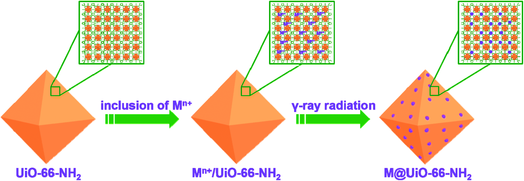 | ||
| Scheme 1 Schematic illustration of the synthetic route for the formation of metal nanoparticles inside UiO-66-NH2via the γ-ray radiation approach. | ||
Apparently, increasing the dose rate could lead to a higher concentration of reducing species from water radiolysis, causing rapid reduction of metal ions and thus creating a large number of nucleated Pd0 seeds which is beneficial for the formation of uniform Pd NPs. On the other hand, increasing absorbed doses could reduce more metal ions, resulting in a large number of Pd NPs encapsulated in UiO-66-NH2 (Table S2†); however, excessively absorbed doses inevitably produce Pd particles with large sizes as shown in Fig. S2c.† Therefore, considering both the dose rates and absorbed doses, Pd@UiO-66-NH2/R was prepared at a dose rate of 100 Gy min−1 with the absorbed dose of 18 kGy.
In addition, the amount of K2PdCl4 impregnated in UiO-66-NH2 is another important parameter for the synthesis of Pd NPs inside MOFs. From Fig. S3 and Table S3,† it can be seen that when the concentration of K2PdCl4 increased from 0.002 M to 0.005 M then to 0.010 M, the diameter of Pd NPs increases from 1.7 nm to 1.9 nm then to 3.7 nm. Accordingly, the amount of Pd inside MOFs increases from 1.52 wt% to 3.55 wt% and then to 6.90 wt% as determined from ICP-MS. Therefore, the concentration of K2PdCl4 was maintained below 0.005 M during the synthesis to obtain ultrasmall Pd NPs. As shown in Fig. 1a, the high-resolution TEM image clearly reveals the formation of uniform Pd NPs inside UiO-66-NH2. Meanwhile, the high-angle annular dark-field scanning TEM (HAADF-STEM) image further confirms the uniformity of the Pd NPs in the UiO-66-NH2 framework (Fig. 1b). Moreover, the corresponding elemental mapping results further verify that Pd NPs are evenly distributed inside the MOFs. Due to a similar contrast of Zr-oxo clusters in UiO-66-NH2 to that of Pd NPs upon exposure to an electron beam, there are probably some indiscernible Pd NPs with less than 1 nm in diameter in the UiO-66-NH2 framework. Although a small fraction of Pd NPs are larger than the pore size of UiO-66-NH2 (∼12 Å),61 the pore structure could offer spatial restriction to Pd NPs to some extent in accordance with previous reports.29,62
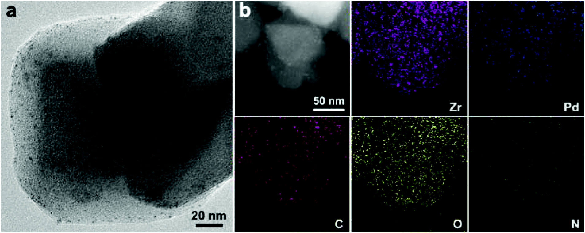 | ||
| Fig. 1 (a) TEM image of Pd@UiO-66-NH2/R (3.55 wt% Pd). (b) HAADF-STEM image and the corresponding elemental mapping images of Zr, Pd, C, O, and N. | ||
Fig. 2a shows the PXRD patterns of Pd@UiO-66-NH2/R catalysts along with the simulated UiO-66-NH2. Obviously, the diffraction patterns of Pd@UiO-66-NH2/R catalysts are identical to the simulated structure, indicating that the crystal structure of UiO-66-NH2 was well retained. The characteristic peak of Pd (111) at 2θ ≈ 40.1° was absent in the PXRD patterns, which could presumably be related to the low content and the small size of generated Pd NPs.29 The nitrogen sorption isotherms indicated that UiO-66-NH2 exhibited a BET surface area about 1126 m2 g−1 (Fig. 2b). After immobilizing Pd NPs, the specific surface area decreased significantly to 782 and 750 m2 g−1 for 1.52 and 3.55 wt% Pd@UiO-66-NH2/R, respectively. Meanwhile, the pore volume of Pd@UiO-66-NH2/R also decreased compared to UiO-66-NH2 (Table S4†), indicating that the cavities were occupied by the formed Pd NPs.
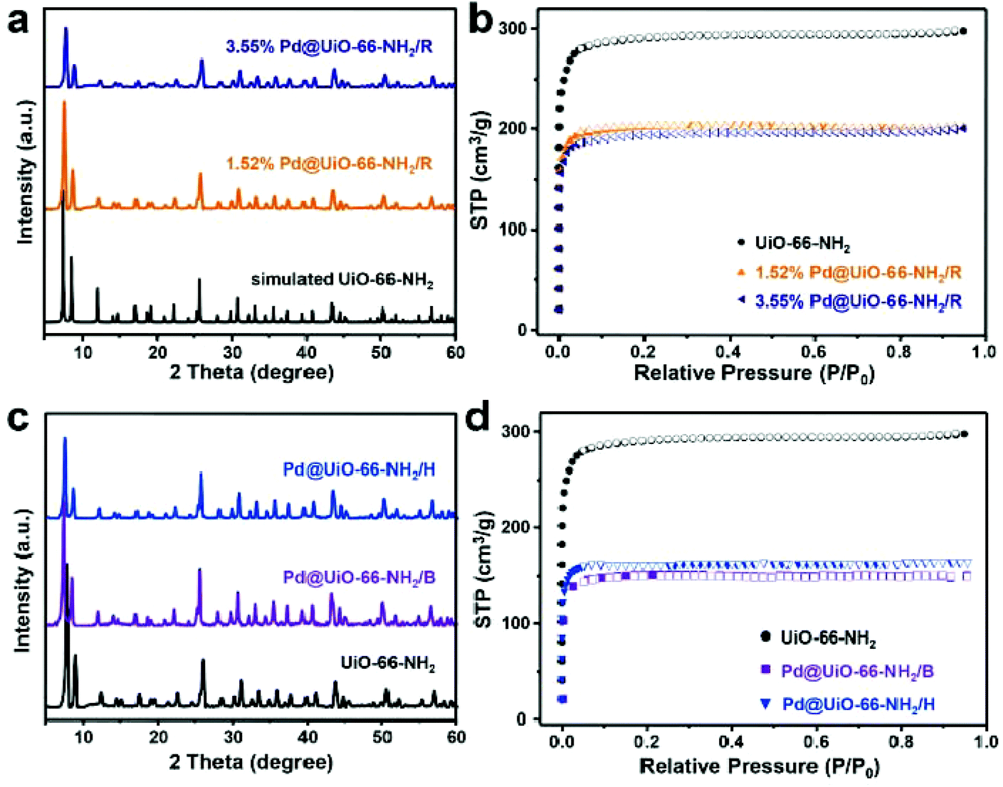 | ||
| Fig. 2 (a) PXRD patterns and (b) nitrogen adsorption and desorption isotherms of UiO-66-NH2, Pd@UiO-66-NH2/R (1.52 and 3.55 wt% Pd). (c) PXRD patterns and (d) nitrogen adsorption and desorption isotherms of UiO-66-NH2, Pd@UiO-66-NH2/B, and Pd@UiO-66-NH2/H. | ||
To evaluate the advantages of the proposed γ-ray radiation strategy, other reducing methods were also employed to prepare Pd@UiO-66-NH2 catalysts for comparison (see the Experimental section for details). The PXRD patterns indicated the crystallinity of UiO-66-NH2 still maintained in Pd@UiO-66-NH2/H and Pd@UiO-66-NH2/B (Fig. 2c). The measured BET surface areas of Pd@UiO-66-NH2/H and Pd@UiO-66-NH2/B were 608 and 585 m2 g−1, respectively (Fig. 2d). These values were much lower than that of the Pd@UiO-66-NH2/R catalyst even with the higher Pd loading amount (Tables S3 and S4†). Moreover, the pore volume of Pd@UiO-66-NH2/R was larger than those of Pd@UiO-66-NH2/H and Pd@UiO-66-NH2/B. Further microstructure examination using TEM (Fig. S4†) indicated that large Pd nanoparticles were formed both in Pd@UiO-66-NH2/H and Pd@UiO-66-NH2/B with heterogeneous distribution. These results clearly indicate that γ-ray radiation is a novel approach to achieve Pd NPs with uniform distribution in porous frameworks.
XPS was performed to examine the composition and the valence state of the as-synthesized Pd NPs. As shown in Fig. S5,† it can be clearly seen that the 3d5/2 and 3d3/2 peaks of Pd0 appear at 338.1 and 343.5 eV, respectively. Both peaks slightly shift to the higher energy due to the interaction between Pd and Zr.63 It is noteworthy that there is an additional small peak at ca. 341.3 eV in the Pd@UiO-66-NH2/H and Pd@UiO-66-NH2/B. This peak was probably ascribed to the absorbed Pd2+ by the amine groups in UiO-66-NH2 during impregnation and/or the oxidized Pd NPs distributed on the outer surface of MOFs. They were not only difficult to be removed by repeated washing but also difficult to be completely reduced by H2 or NaBH4 due to the limited diffusion of H2 or NaBH4 into the porous MOFs. In sharp contrast, the Pd2+ peak could not be observed in Pd@UiO-66-NH2/R, suggesting that γ-ray radiation is very efficient to reduce Pd2+ into Pd0 with high penetration capability. Moreover, the Pd content of 3.55 wt% Pd@UiO-66-NH2/R measured from the XPS analysis was lower than that found in Pd@UiO-66-NH2/H and Pd@UiO-66-NH2/B, although ICP-MS measurements revealed that Pd@UiO-66-NH2/R possessed much higher Pd content (Table S3†). This observation clearly confirms that γ-ray radiation could reduce most of the Pd2+ inside the UiO-66-NH2 frameworks through using the in situ generated H˙ and e−aq, whereas other methods only reduce Pd2+ located near the surface region of the MOFs due to the limited diffusion of H2 or NaBH4. This observation is also consistent with the colour variance in the obtained Pd@UiO-66-NH2 samples (Fig. S6†). Furthermore, although the impregnation condition was the same for all samples and almost all Pd2+ (99.99%, calculated by ICP-MS) were absorbed by UiO-66-NH2, the Pd content in Pd@UiO-66-NH2/R (3.55 wt%) is much higher than those obtained by H2 reduction (2.12 wt%) and NaBH4 reduction (2.35 wt%). Therefore, γ-radiation reduction stands out as a unique method to encapsulate ultrasmall metal NPs into MOFs due to the high penetrability of γ-rays and strong reduction capability of active species generated by γ-ray radiation.
The liquid-phase hydrogenation of olefins with different molecular sizes (1-hexene, trans-stilbene, and tetraphenylethylene) was carried out over Pd@UiO-66-NH2/R and Pd/C to verify the size-selective catalysis of Pd@UiO-66-NH2/R based on the fact that Pd NPs were confined in the UiO-66-NH2 frameworks. As shown in Fig. 3, Pd@UiO-66-NH2/R exhibits different conversion rates for olefins with different molecular sizes. For 1-hexene (2.5 Å), Pd@UiO-66-NH2/R shows the highest activity with a 99.5% conversion rate after the 24 h reaction while the Pd/C catalyst exhibits a similar conversion rate (99.2%), indicating that there is no obvious difference between Pd@UiO-66-NH2/R and Pd/C for the catalytic hydrogenation of small molecules. The reason is that the molecular size of 1-hexene is much smaller than the pore aperture of UiO-66-NH2 (6 Å),42 and thus the diffusion of 1-hexene is barely hindered by UiO-66-NH2. trans-Stilbene has a much larger molecular size (5.6 Å) than 1-hexene and the conversion rate decreases to 83.2% using Pd@UiO-66-NH2/R. In contrast, Pd/C displays a much lower conversion rate of 70.4%. Moreover, Pd@UiO-66-NH2/R is not active toward the hydrogenation of tetraphenylethylene (6.7 Å), whereas Pd/C shows a moderate activity of 41.7% conversion rate (Fig. S7†). This is because tetraphenylethylene is too large to diffuse through the aperture of UiO-66-NH2 and thus could not be catalysed by the Pd NPs confined inside the MOFs. The above results confirm that Pd NPs are confined inside the UiO-66-NH2 frameworks.
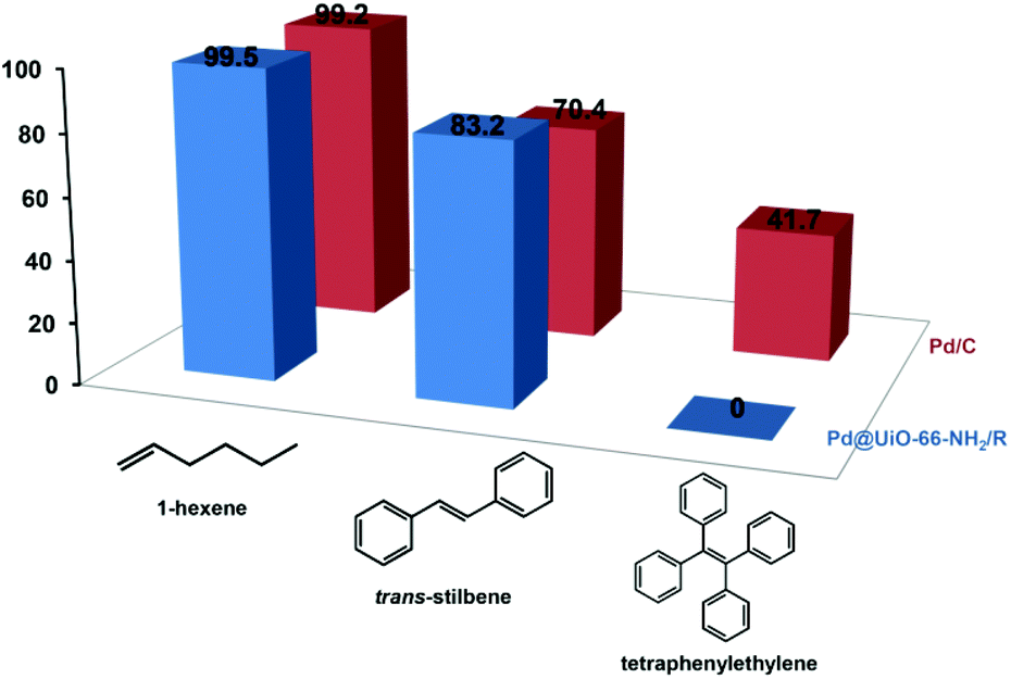 | ||
| Fig. 3 Catalytic performance of Pd@UiO-66-NH2/R (3.55 wt% Pd) for the liquid-phase hydrogenation of olefins with different molecular sizes. The Pd/C catalyst (5 wt%) was used as a control. | ||
Subsequently, the hydrogenation of styrene was performed over different heterogeneous Pd@UiO-66-NH2 catalysts to evaluate the catalytic performance. As shown in Fig. 4a, under the given reaction conditions (the molar ratio of Pd to styrene was 1:100), Pd@UiO-66-NH2/R exhibits the highest catalytic efficiency among different Pd@UiO-66-NH2 catalysts. The hydrogenation of styrene using Pd@UiO-66-NH2/R with Pd loading of 1.52 wt%, 3.55 wt% and 6.90 wt% could be completed (100% conversion) within 45 min, 50 min and 70 min, respectively, whereas Pd@UiO-66-NH2/H and Pd@UiO-66-NH2/B required 130 min and 140 min, respectively. The catalytic performance of Pd@UiO-66-NH2/R was also superior to most of the reported Pd/MOF-based catalysts as shown in Table S5.† Meanwhile, pure UiO-66-NH2 frameworks were not catalytically active toward the unsaturated olefin. These results suggest that the diameter, distribution, and surface-clean surface of Pd NPs could have a significant influence on the catalytic performance. 1.52 wt% Pd@UiO-66-NH2/R is slightly more efficient than 3.55 wt% Pd@UiO-66-NH2/R and 6.90 wt% Pd@UiO-66-NH2/R owing to its smaller particle size as shown in Fig. S3.† Therefore, the high catalytic activity of Pd@UiO-66-NH2/R could be attributed to the uniformly dispersed and highly active Pd NPs derived from γ-ray radiation. Furthermore, a hot-filtration experiment was conducted to investigate whether the reaction proceeded in a heterogeneous model. After the reaction proceeded for 20 min over different Pd@UiO-66-NH2 catalysts, the solid catalysts were separated by hot-filtration and the filtrates were further maintained at the same temperature for additional 40 min. Obviously, the reaction was completely terminated after the removal of catalysts (Fig. S8†), suggesting that hydrogenation of styrene proceeds over the metal surface via a heterogeneous manner.
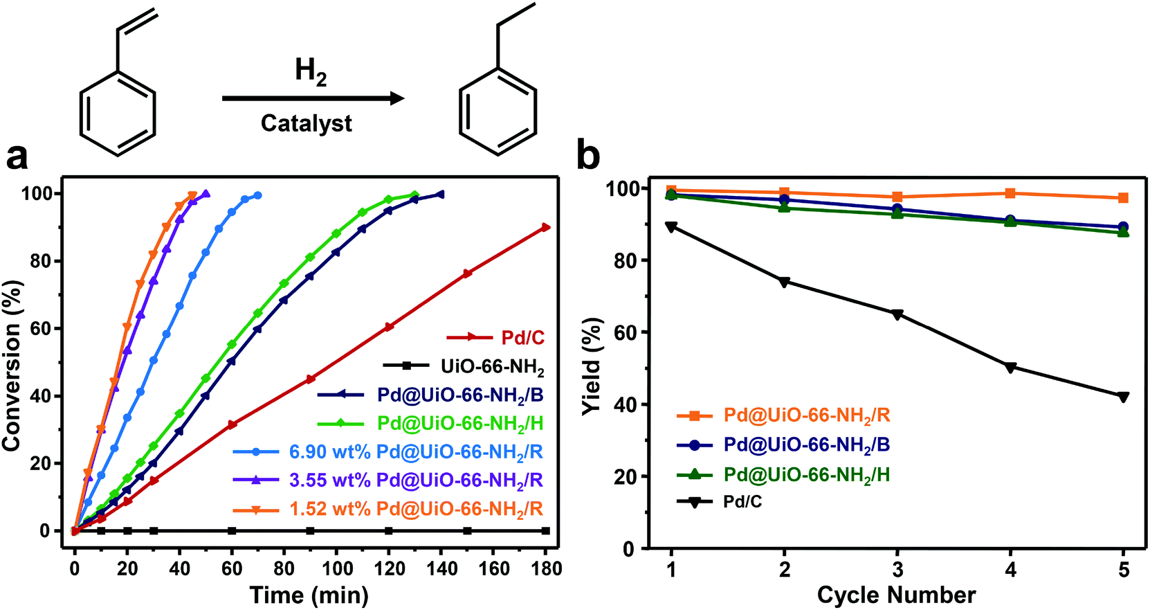 | ||
| Fig. 4 (a) Conversion of styrene as a function of the reaction time for Pd@UiO-66-NH2 catalysts synthesized by different reduction methods (the molar ratio of Pd:styrene = 1:100). Pure UiO-66-NH2 and Pd/C (5 wt%) were used as controls. (b) Durability and recyclability tests of different catalysts: Pd@UiO-66-NH2/R (3.55 wt%), Pd@UiO-66-NH2/H (2.12 wt%), Pd@UiO-66-NH2/B (2.35 wt%), and Pd/C (5 wt%). | ||
The stability of these heterogeneous catalysts was further evaluated for five consecutive catalytic cycles. As shown in Fig. 4b, the catalytic activity of Pd@UiO-66-NH2/R remains almost the same for five cycles, whereas Pd@UiO-66-NH2/H and Pd@UiO-66-NH2/B exhibit gradual loss in catalytic performance after five cycles. We analysed the liquid phase of the reaction mixtures through hot-filtration after the first cycle by ICP-MS. It turned out that only 0.75 ppm of Pd leached out from Pd@UiO-66-NH2/R, which was much lower than those observed in Pd@UiO-66-NH2/H (6.06 ppm) and Pd@UiO-66-NH2/B (6.07 ppm). Consequently, Pd@UiO-66-NH2/R exhibited much enhanced stability during cycling tests. Meanwhile, detailed characterization using TEM indicated that no obvious aggregation could be observed in Pd@UiO-66-NH2/R even after five consecutive tests (Fig. S4†). However, severe agglomeration of Pd nanoparticles can be observed in both Pd@UiO-66-NH2/H and Pd@UiO-66-NH2/B (Fig. S4†). More importantly, all samples were subjected to calcination at 250 °C under air for 2 h and only Pd NPs in Pd@UiO-66-NH2/R still remained in the dispersed state. These results clearly reveal the excellent stability of Pd@UiO-66-NH2/R due to the fact that γ-ray radiation could generate highly dispersed Pd NPs confined within the MOFs to avoid aggregation.
We also conducted X-ray diffraction and N2 sorption measurements for the Pd@UiO-66-NH2/R after cycling tests. The crystal structure of UiO-66-NH2 still maintained after five cycles (Fig. S9†), and the BET surface area and the pore volume slightly decreased to 688 m2 g−1 (Fig. S10†) and 0.29 cm3 g−1 (Table S4†), respectively. The slight variation in the BET surface area and pore volume could be caused by the residual reactants or products trapped inside the Pd@UiO-66-NH2/R.32 Moreover, XPS analysis indicated that the 3d5/2 and 3d3/2 Pd peaks in Pd@UiO-66-NH2/R remained unchanged after five cycles (Fig. S11†).
Furthermore, the catalytic reduction of 4-nitrophenol by NaBH4 was also employed as a model reaction to evaluate the catalytic activity of Pd@UiO-66-NH2 samples prepared using different methods. As shown in Fig. S12–S15,† it is obvious that the intensity of the characteristic absorption peak of 4-nitrophenol at 400 nm decreases quickly in the presence of catalysts and the characteristic absorption of 4-aminophenol at ∼305 nm appears and gradually increases with reaction time. The reduction of 4-nitrophenol completed in 355 s after adding Pd@UiO-66-NH2/R (Fig. S12†). In contrast, the reaction took much longer time to complete when Pd@UiO-66-NH2/H (580 s), Pd@UiO-66-NH2/B (640 s) and Pd/C (860 s) were used as the catalyst. Moreover, according to the slope of the fitted line plotted with ln(Ct/C0) versus the reaction time (Fig. 5), the kinetic constant kapp for the reduction of 4-nitrophenol over Pd@UiO-66-NH2/R was 0.02425 s−1 (1.455 min−1) which is much higher than those obtained in Pd@UiO-66-NH2/B (1.126 min−1), Pd@UiO-66-NH2/H (1.123 min−1) and Pd/C (0.341 min−1). This value is also much better than other Pd-based catalysts (Table S6†), implying that γ-ray radiation is a powerful tool to prepare ultrasmall Pd NPs with excellent catalytic performance.
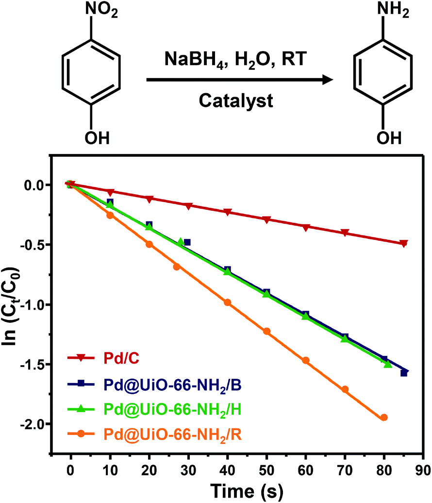 | ||
| Fig. 5 Plots of ln(Ct/C0) at 400 nm versus the reaction time for Pd@UiO-66-NH2 synthesized by different reduction methods and Pd/C (5 wt%) as a control (molar ratio of Pd:4-nitrophenol = 1:150). | ||
Our study demonstrates that γ-ray radiation reduction is a facile and efficient approach to in situ generate Pd NPs inside UiO-66-NH2. This approach could also be extended to encapsulate other metal NPs into UiO-66-NH2. For example, we used the same strategy to successfully obtain highly dispersed Pt and Au NPs inside UiO-66-NH2 frameworks. As shown in Fig. 6a and b, TEM images clearly reveal that highly dispersed Pt and Au NPs with an average diameter of ∼1.0 nm are encapsulated inside the UiO-66-NH2 frameworks. The corresponding elemental mapping images further indicate that Pt and Au are evenly dispersed within UiO-66-NH2 (Fig. 6c and d). Furthermore, the structural integrity of UiO-66-NH2 could be maintained in both Pt@UiO-66-NH2/R and Au@UiO-66-NH2/R and no detectable diffraction peaks of Pt and Au were observed (Fig. S16†). The nitrogen sorption isotherms of Pt@UiO-66-NH2/R and Au@UiO-66-NH2/R exhibited the similar features to those of Pd@UiO-66-NH2/R (Fig. S17†). Furthermore, γ-ray radiation reduction also works well in generating metal NPs in situ inside other MOFs. Fig. S18† shows Pd@MIL-101/R and Pt@MIL-101/R as examples. Therefore, the newly developed γ-ray radiation approach is very versatile for the synthesis of highly active metal NPs inside MOFs with excellent stability and catalytic performance.
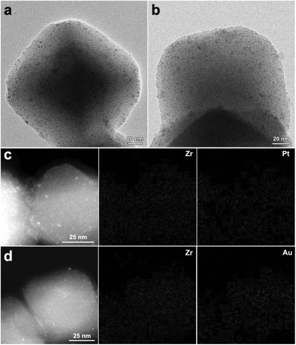 | ||
| Fig. 6 TEM images of (a) Pt@UiO-66-NH2/R and (b) Au@UiO-66-NH2/R synthesized through the γ-ray radiation method. HAADF-STEM images of (c) Pt@UiO-66-NH2/R and (d) Au@UiO-66-NH2/R and their corresponding elemental mapping images. | ||
4. Conclusions
In conclusion, we have successfully demonstrated a novel γ-ray radiation approach for the synthesis of highly dispersed Pd NPs with uniform sizes inside MOFs. The confined Pd NPs in Pd@UiO-66-NH2/R exhibited enhanced catalytic performance and improved stability in olefin hydrogenation and catalytic reduction of 4-nitrophenol compared to Pd@UiO-66-NH2/H and Pd@UiO-66-NH2/B, indicating that the surface-clean metal NPs generated inside MOFs using this approach are very promising for catalytic applications. Our study also reveals that this γ-ray radiation method is more efficient in converting metal ions into catalytically active metal species. Considering that the radiation technique is widely used in industry, this approach could potentially produce other MOF composites in a scalable manner. Studies aimed at extending this methodology to encapsulate other catalytic species into MOFs for more intriguing catalytic applications are currently underway in our laboratory.Conflicts of interest
There are no conflicts to declare.Acknowledgements
We acknowledge the funding support from MOST (2015CB351903, 2017YFA0207301, and 2014CB931803), National Natural Science Foundation of China (51402282, 51373160, 21474095, 21371162, 21673213, and 21521001), CAS Key Research Program of Frontier Sciences (QYZDB-SSW-SLH018), and the Fundamental Research Funds for the Central Universities.References
- Y. J. Colón and R. Q. Snurr, Chem. Soc. Rev., 2014, 43, 5735–5749 RSC.
- W. Zhang, Y. Liu, G. Lu, Y. Wang, S. Li, C. Cui, J. Wu, Z. Xu, D. Tian, W. Huang, J. S. Ducheneu, W. D. Wei, H. Chen, Y. Yang and F. W. Huo, Adv. Mater., 2015, 27, 2923–2929 CrossRef CAS PubMed.
- W. Lu, Z. Wei, Z.-Y. Gu, T.-F. Liu, J. Park, J. Park, J. Tian, M. Zhang, Q. Zhang, T. Gentle III, M. Bosch and H.-C. Zhou, Chem. Soc. Rev., 2014, 43, 5561–5593 RSC.
- J. K. Guo, K. Q. Ye, M. He, W.-W. Xiong, W. F. Cao, Z. Y. Lee, Y. Wang, T. Wu, F. W. Huo, X. G. Liu and Q. C. Zhang, J. Solid State Chem., 2013, 206, 27–31 CrossRef.
- J. Zhao, Y. N. Wang, W. W. Dong, Y. P. Wu, D. S. Li, B. Liu and Q. C. Zhang, Chem. Commun., 2015, 51, 9479–9482 RSC.
- J. R. Li, J. Sculley and H.-C. Zhou, Chem. Rev., 2012, 112, 869–932 CrossRef CAS PubMed.
- X. Cui, K. Chen, H. Xing, Q. Yang, R. Krishna, Z. Bao, H. Wu, W. Zhou, X. Dong, Y. Han, B. Li, Q. Ren, M. J. Zaworotko and B. L. Chen, Science, 2016, 353, 141–144 CrossRef CAS PubMed.
- A. Cadiau, K. Adil, P. M. Bhatt, Y. Belmabkhout and M. Eddaoudi, Science, 2016, 353, 137–140 CrossRef CAS PubMed.
- T. A. Makal, J.-R. Li, W. Lu and H.-C. Zhou, Chem. Soc. Rev., 2012, 41, 7761–7779 RSC.
- S. Chaemchuen, N. A. Kabir, K. Zhou and F. Verpoort, Chem. Soc. Rev., 2013, 42, 9304–9332 RSC.
- L.-B. Sun, A.-G. Li, X.-D. Liu, X.-Q. Liu, D. Feng, W. Lu, D. Yuan and H.-C. Zhou, J. Mater. Chem. A, 2015, 3, 3252–3256 CAS.
- L. E. Kreno, K. Leong, O. K. Farha, M. Allendorf, R. P. Van Duyne and J. T. Hupp, Chem. Rev., 2012, 112, 1105–1125 CrossRef CAS PubMed.
- Z. Hu, B. J. Deibert and J. Li, Chem. Soc. Rev., 2014, 43, 5815–5840 RSC.
- M. D. Allendorf, C. A. Bauer, R. K. Bhakta and R. J. T. Houk, Chem. Soc. Rev., 2009, 38, 1330–1352 RSC.
- J. Della Rocca, D. Liu and W. Lin, Acc. Chem. Res., 2011, 44, 957–968 CrossRef CAS PubMed.
- P. Horcajada, R. Gref, T. Baati, P. K. Allan, G. Maurin, P. Couvreur, G. Férey, R. E. Morris and C. Serre, Chem. Rev., 2012, 112, 1232–1268 CrossRef CAS PubMed.
- Q. H. Yang, Q. Xu, S.-H. Yu and H.-L. Jiang, Angew. Chem., Int. Ed., 2016, 55, 3685–3689 CrossRef CAS PubMed.
- A. Dhakshinamoorthy and H. Garcia, Chem. Soc. Rev., 2014, 43, 5750–5765 RSC.
- Q. H. Yang, Q. Xu and H.-L. Jiang, Chem. Soc. Rev., 2017, 46, 4774–4808 RSC.
- X.-Q. Wu, D.-D. Huang, Z.-H. Zhou, W.-W. Dong, Y.-P. Wu, J. Zhao, D.-S. Li, Q. C. Zhang and X. H. Buc, Dalton Trans., 2017, 46, 2430–2438 RSC.
- G.-W. Xu, Y.-P. Wu, W.-W. Dong, J. Zhao, X.-Q. Wu, D.-S. Li and Q. C. Zhang, Small, 2017, 13, 1602996 CrossRef PubMed.
- P. Valvekens, F. Vermoortele and D. De Vos, Catal. Sci. Technol., 2013, 3, 1435–1445 CAS.
- M. Yoon, R. Srirambalaji and K. Kim, Chem. Rev., 2012, 112, 1196–1231 CrossRef CAS PubMed.
- A. Dhakshinamoorthy, Chem. Soc. Rev., 2012, 41, 5262–5284 RSC.
- L.-B. Sun, X.-Q. Liu and H.-C. Zhou, Chem. Soc. Rev., 2015, 44, 5092–5147 RSC.
- S. Li and F. W. Huo, Nanoscale, 2015, 7, 7482–7501 RSC.
- Q.-L. Zhu and Q. Xu, Chem, 2016, 1, 220–245 CAS.
- W. Zhou, B. Zou, W. Zhang, D. Tian, W. Huang and F. W. Huo, Nanoscale, 2015, 7, 8720–8724 RSC.
- G. Huang, Q. H. Yang, Q. Xu, S.-H. Yu and H.-L. Jiang, Angew. Chem., Int. Ed., 2016, 55, 7379–7383 CrossRef CAS PubMed.
- I. Luz, C. Rösler, K. Epp, F. X. LlabresiXamena and R. A. Fischer, Eur. J. Inorg. Chem., 2015, 32, 3904–3912 CrossRef.
- A. Aijaz, A. Karkamkar, Y. J. Choi, N. Tsumori, E. Rönnebro, T. Autrey, H. Shioyama and Q. Xu, J. Am. Chem. Soc., 2012, 134, 13926–13929 CrossRef CAS PubMed.
- X. Li, Z. Guo, C. Xiao, T. W. Goh, D. Tesfagaber and W. Y. Huang, ACS Catal., 2014, 4, 3490–3497 CrossRef CAS.
- Z. Guo, C. Xiao, R. V. Maligal-Ganesh, L. Zhou, T. W. Goh, X. Li, D. Tesfagaber, A. Thiel and W. Y. Huang, ACS Catal., 2014, 4, 1340–1348 CrossRef CAS.
- H. Liu, L. Chang, C. Bai, L. Chen, R. Luque and Y. W. Li, Angew. Chem., Int. Ed., 2016, 55, 5019–5023 CrossRef CAS PubMed.
- Y. F. Yang, F. W. Wang, Q. H. Yang, Y. L. Hu, H. Yan, Y. Z. Chen, H. R. Liu, G. Q. Zhang, J. L. Lu, H.-L. Jiang and H. X. Xu, ACS Appl. Mater. Interfaces, 2014, 6, 18163–18171 CAS.
- M. Zhao, K. Deng, L. He, Y. Liu, G. Li, H. J. Zhao and Z. Y. Tang, J. Am. Chem. Soc., 2014, 136, 1738–1741 CrossRef CAS PubMed.
- C. Kuo, Y. Tang, L. Chou, B. T. Sneed, C. N. Brodsky, Z. Zhao and C.-K. Tsung, J. Am. Chem. Soc., 2012, 134, 14345–14348 CrossRef CAS PubMed.
- P. Wang, J. Zhao, X. Li, Y. Yang, Q. Yang and C. Li, Chem. Commun., 2013, 49, 3330–3332 RSC.
- T. Tsuruoka, H. Kawasaki, H. Nawafuneand and K. Akamatsu, ACS Appl. Mater. Interfaces, 2011, 3, 3788–3791 CAS.
- H. L. Liu, L. Chang, L. Chen and Y. W. Li, J. Mater. Chem. A, 2015, 3, 8028–8033 CAS.
- W. Dong, C. Feng, L. Zhang, N. Shang, S. Gao, C. Wang and Z. Wang, Catal. Lett., 2016, 146, 117–125 CrossRef CAS.
- C. Liang, W. Xia, H. Soltani-Ahmadi, O. Schluter, R. A. Fischer and M. Muhler, Chem. Commun., 2005, 2, 282–284 RSC.
- C. Dispenza, N. Grimaldi, M. A. Sabatino, I. L. Soroka and M. Jonsson, J. Nanosci. Nanotechnol., 2015, 15, 3445–3467 CrossRef CAS PubMed.
- H. R. Liu, X. W. Ge, X. Xu, Z. C. Zhang and M. W. Zhang, Radiat. Phys. Chem., 1999, 55, 357–361 CrossRef CAS.
- Y. J. Zhang, Y. T. Qian, M. W. Zhang, Z. Y. Chen, B. Lu and C. S. Wang, Mater. Lett., 1993, 17, 314–318 CrossRef.
- L. He, L. F. Dumée, D. Liu, L. Velleman, F. She, C. Banos, J. B. Davies and L. Kong, RSC Adv., 2015, 5, 10707–10715 RSC.
- J. L. Marignier, J. Belloni, M. O. Delcourt and J. P. Chevalier, Nature, 1985, 317, 344–345 CrossRef CAS.
- P. Yadav, R. T. Olsson and M. Jonsson, Radiat. Phys. Chem., 2009, 78, 939–944 CrossRef CAS.
- L. M. Alrehaily, J. M. Joseph, M. C. Biesinger, D. A. Guzonas and J. C. Wren, Phys. Chem. Chem. Phys., 2013, 15, 1014–1024 RSC.
- Y. P. Liu, Y. Zhang, M. W. Zhang, W. Zhang, Y. T. Qian, L. Yang, C. Wang and Z. Chen, Mater. Sci. Eng., B, 1997, 49, 42–45 CrossRef.
- P. A. Yakabuskie, J. M. Joseph, P. Keech, G. A. Botton, D. Guzonas and J. C. Wren, Phys. Chem. Chem. Phys., 2011, 13, 7198–7206 RSC.
- H. S. Bae, E. H. Shim, J. Hoon Park and H. Jung, J. Phys. Chem. Solids, 2012, 73, 1456–1459 CrossRef CAS.
- S. W. Kim, B. J. Kwon, J. H. Park, M. G. Hur, S. D. Yang and H. Jung, Bull. Korean Chem. Soc., 2010, 31, 910–914 CrossRef CAS.
- A. Kharazmi, E. Saion, N. Faraji, N. Soltani and A. Dehzangi, Chin. Phys. Lett., 2013, 30, 057803–057807 CrossRef.
- A. K. Sahoo, S. K. Srivastava, P. K. Raul, A. K. Gupta and R. Shrivastava, J. Nanopart. Res., 2014, 16, 2473–2489 CrossRef.
- Y. D. Yin, X. Xu, X. W. Ge, Y. Lu and Z. C. Zhang, Radiat. Phys. Chem., 1999, 55, 353–356 CrossRef CAS.
- Y. D. Yin, X. Xu and Z. C. Zhang, Chem. Commun., 1998, 16, 1641–1642 RSC.
- S. H. Choi, Y. P. Zhang, A. Gopalan, K. P. Lee and H. D. Kang, Colloids Surf., A, 2005, 256, 165–170 CrossRef CAS.
- J. H. Cavka, S. Jakobsen, U. Olsbye, N. Guillou, C. Lamberti, S. Bordiga and K. P. Lillerud, J. Am. Chem. Soc., 2008, 130, 13850–13851 CrossRef PubMed.
- J. V. Rojas and C. H. Castano, Radiat. Phys. Chem., 2012, 81, 16–21 CrossRef CAS.
- X. Li, T. W. Goh, L. Li, C. Xiao, Z. Guo, X. C. Zeng and W. Y. Huang, ACS Catal., 2016, 6, 3461–3468 CrossRef CAS.
- L. Chen, H. Chen, R. Luque and Y. Li, Chem. Sci., 2014, 5, 3708–3714 RSC.
- R. Kardanpour, S. Tangestaninejad, V. Mirkhani, M. Moghadam, I. Mohammadpoor-Baltork, A. R. Khosropour and F. Zadehahmadi, J. Organomet. Chem., 2014, 761, 127–133 CrossRef CAS.
Footnote |
| † Electronic supplementary information (ESI) available: Additional table of experimental conditions, PXRD, TEM, XPS, 1H NMR, nitrogen adsorption and desorption isotherms, UV-Vis absorption spectra characterization results. See DOI: 10.1039/c7qi00577f |
| This journal is © the Partner Organisations 2018 |