 Open Access Article
Creative Commons Attribution 3.0 Unported Licence
Analysis of the reaction mechanism of the thiol–epoxy addition initiated by nucleophilic tertiary amines
Ali Osman
Konuray
,
Xavier
Fernández-Francos
 * and
Xavier
Ramis

Thermodynamics Laboratory, ETSEIB, Universitat Politècnica de Catalunya, Av. Diagonal 647, 08028 Barcelona, Spain. E-mail: xavier.fernandez@mmt.upc.edu; Fax: +34 934017389; Tel: +34 934017955
First published on 30th August 2017
Abstract
A kinetic model for thiol–epoxy crosslinking initiated by tertiary amines has been proposed. The kinetic model is based on mechanistic considerations and it features the effect of the initiator, hydroxyl content, and thiol–epoxy ratios. The results of the kinetic model have been compared with data from the curing of off-stoichiometric formulations of diglycidyl ether of bisphenol A (DGEBA) crosslinked with trimethylolpropane tris(3-mercaptopropionate) (S3) using 1-methylimidazole (1MI) as the initiator. The model has been validated by fitting the kinetic parameters to the experimental data under a variety of reaction conditions. In spite of the experimental uncertainty and model assumptions, the main features of the curing kinetics are correctly described and the reaction rates are quantitatively reproduced.
1 Introduction
Base-catalyzed thiol–epoxy polymerization is of industrial relevance in the area of adhesives, high performance coatings and composites.1 A remarkable feature of thiol–epoxy condensation is that it can be categorized as a click reaction, which means that it is selective, leaves no by-products and it takes place quantitatively and under mild reactive conditions. Thus, it is possible to use it not only in conventional reactive formulations but also in dual-curable systems with a controlled curing sequence such as thiol–ene/thiol–epoxy,2–5 off-stoichiometric thiol–epoxy systems,6 or even in combination with inorganic network precursors in hybrid systems.7 Thiol–epoxy thermosets are highly transparent, which is favorable for their application as clearcoats8 and generally highly flexible,9 but this latter feature is also a drawback because their low Tg can limit their use in more temperature-demanding applications.10 In order to enhance the thermal–mechanical characteristics of thiol–epoxy, different strategies can be adopted, such as the use of more rigid and functional epoxy resins10 and the development of novel highly-functional thiol crosslinkers11 in stoichiometric thiol–epoxy systems, or the use of excess epoxy in off-stoichiometric thiol–epoxy systems.6 Another severe drawback is the fact that the most commonly used catalysts for the thiol–epoxy addition, namely, basic tertiary amines are not latent and therefore, it makes difficult the handling and control of the processing of thiol–epoxy formulations once prepared.2,9 Therefore, research efforts are directed towards the exploration of catalytic systems with thermal latency9 or the development of photolatent bases.7,8,12,13 Remarkably, some of these photolatent bases have been shown to be activated by both UV-light and temperature,14 which turns them into highly versatile catalytic systems. Another interesting research line is the use of tertiary amines with poor basicity but with nucleophilic characteristics6,15 that are not latent but with sufficiently slow activation and a strong auto-accelerating effect so as to permit safe formulation preparation and manipulation as well as complete curing at low temperature in short times.The curing mechanism of the base-catalyzed thiol–epoxy condensation is assumed to be a simple nucleophilic addition between thiolate and epoxy groups.2 In the presence of sufficiently strong bases, an acid–base proton exchange leads to the deprotonation of the thiol, producing a thiolate anion that is nucleophilic enough to attack the epoxy ring. The thiol–epoxy reaction is strongly autocatalytic due to the formation of hydroxyl groups that facilitate the ring-opening of the epoxy group.16 The reaction mechanism can become more complex in the presence of nucleophilic tertiary amine catalysts, such as benzyldimethylamine (BDMA) and 1-methylimidazole (1MI), which lead to a very slow initiation process followed by a strong autoacceleration up to the completion of the curing process.6,15 Loureiro et al. proposed a reaction mechanism to describe the curing kinetics of thiol–epoxy addition catalyzed by a tertiary amine, BDMA with poor basicity but a nucleophilic characteristic.15 In a recent study, we have described the dual-curing process of off-stoichiometric thiol–epoxy formulations containing excess epoxy groups.6 We observed that the thiol–epoxy reaction took place very quickly and with a sharp autocatalytic profile, followed at higher temperatures or longer curing times by a slower epoxy homopolymerization process. Although some of these kinetic features can be interpreted in terms of the proposed reaction mechanism,15 it should be modified in order to take into account properly the effect of initiation/termination reactions and the effect of the decreasing thiol group content.
The aim of this paper is to develop a consistent kinetic model, based on the consideration of the reaction mechanism, capable of capturing the kinetic behaviour during the curing of stoichiometric thiol–epoxy formulations and the first stage of the curing of off-stoichiometric thiol–epoxy formulations. The effect of the thiol–epoxy ratio and the catalyst content will be taken into consideration. The model will be validated experimentally using kinetic data obtained using differential scanning calorimetry.
2 Theoretical
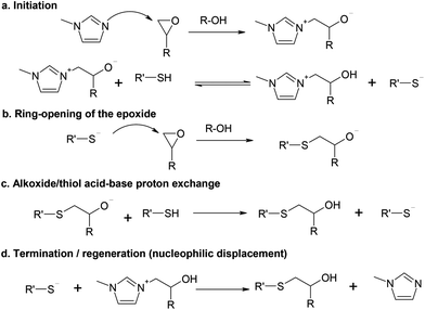
A reaction scheme based on the model of Loureiro et al.15 is shown in Scheme 1, using 1MI as the initiator. In that work, the authors analyzed the curing process of stoichiometric thiol–epoxy formulations using a mechanism-based kinetic model and obtained a reasonable fitting under a wide range of temperatures, catalyst concentrations and curing histories. The active propagating species, the thiolate anion, was produced after nucleophilic addition of BDMA to the epoxy ring and subsequent proton exchange with a thiol group. The effect of the added catalytic hydroxyl groups on the reaction was also analyzed, but it was found that their effect was less important than that of the generated hydroxyl groups by the thiol–epoxy addition. The authors included the effect of termination reactions2,15 and used it to determine the amount of thiolate anions under pseudo-steady state conditions. However, this was an important shortcoming of their model because, eventually, the active thiolate species should be controlled by the available thiol in the reaction medium, not by the amount of epoxy and reaction products. In the work of Jin et al.16 one can also see that the catalytic effect of the added hydroxyl groups (i.e. coming from the epoxy oligomer itself) is less relevant than the autocatalytic effect of the hydroxyl groups generated in the course of the reaction.In the general reaction scheme we propose that the initiation takes place by the nucleophilic attack of 1MI to the epoxy ring (Scheme 1a), leading to the formation of a zwitterion. Contrary to what is stated for common tertiary amines,17 the formation of epoxy–imidazole adducts, including zwitterionic species was convincingly argued by Heise and Martin.18,19 Indeed, epoxy–imidazole adducts are used as curing agents.20 The nucleophilic addition of imidazoles to epoxy groups is catalyzed by proton donors,21 in a similar way to common epoxy–amine systems17 and nucleophilic addition to epoxy groups in general. This was also suggested by the autocatalytic character of the adduct formation between 2,4-unsubstituted imidazoles and epoxides.18,19 In fact, Rozenberg showed that the epoxy homopolymerization could not be initiated by tertiary amines in the absence of proton donors or other catalytic impurities.17
In the presence of thiol groups, a proton exchange would take place leading to the formation of a thiolate anion and a β-hydroxylimidazolium cation.15 The pK of the alcohol–alkoxide equilibrium is much higher than that of the thiol–thiolate equilibrium, and therefore, this exchange should be non-reversible from a practical point of view. However, the pK of the zwitterion system should be lower than that of a common alkoxide due to the stabilization caused by the electron withdrawing effect of the ammonium substituent and possible resonance within the imidazolium ring, in a similar way to the pK of the carboxylic acid proton in amino-acids. Nevertheless, depending on the relative acidity/basicity of the different species, this exchange might be considered almost non-reversible as well. Note that this β-hydroxylimidazolium cation should also have a catalytic effect on the nucleophilic addition to epoxy groups in the presence of both a positive charge and a hydroxyl group.
When the thiolate attack to the epoxy ring takes place (Scheme 1b), an alkoxide anion would be formed, but then fast proton transfer would take place from either a thiol group (Scheme 1c) or the β-hydroxylimidazolium cation, both with a lower pK than an alkoxide, to produce a β-hydroxythioether, the reaction product. The thiol/zwitterion equilibrium should lead to the formation of a thiolate anion that would propagate the reaction. The thiolate addition is also catalyzed by proton donors such as hydroxyl groups, resulting in a strongly autocatalyzed polymerization, as illustrated by Jin et al.16 This autocatalysis is explained by the fact that thiol groups have a negligible effect on proton donors22 and the reaction medium evolves from a thiol-rich environment to a hydroxyl-rich environment.
As the reaction proceeds, the increasing number of initiating species would also lead to an increasing rate of nucleophilic displacement of the initiator and regeneration (Scheme 1d). Thiolate anions are highly nucleophilic23 and far less basic than alkoxide anions, and therefore, initiator regeneration by β-elimination as observed for the anionic homopolymerization of epoxides21,24,25 would not occur.
According to Scheme 1a, when thiol groups are depleted, the equilibrium would shift to the zwitterion form rather than to the thiolate form. If the equilibrium constant is high enough, this equilibrium would shift in a rather abrupt manner, thereby explaining the observed sharp decrease in the reaction rate upon reaching a complete thiol conversion in the off-stoichiometric thiol–epoxy formulations.6 In the absence of thiol groups, the initiation would continue in the presence of the remaining epoxy groups but it would produce only the zwitterionic active species. It should also be noted that, because this zwitterion should be less reactive than a common alkoxide, propagation of the epoxy homopolymerization would not take place just at the end of the thiol–epoxy addition, or else at a very slow rate in comparison.6 This is also supported by the previous results of Heise and Martin, reported on their study of epoxy systems catalyzed by imidazoles,18,19 who observed a clear separation between the epoxy-adduct formation and the epoxy homopolymerization, and stated that the adduct species formed was “dormant” before homopolymerization of the excess of epoxy groups started.
Some more mechanistic considerations can be made if we analyze a similar polymerization process, the nucleophile-catalyzed phenol–epoxy polymerization. The overall reaction mechanism23,26–29 is similar to that shown in Scheme 1. It is of particular relevance to the fact that, in off-stoichiometric phenol–epoxy formulations, the phenol–epoxy reaction takes place first, and once phenol groups are exhausted, homopolymerization of excess epoxy groups can take place,23 like in thiol–epoxy systems.6 However, a fundamental difference is that the phenol–epoxy reaction is much slower due to the stability and lower nucleophilicity of the phenolate anion, making the separation between phenol–epoxy and epoxy homopolymerization less clear.23,26,28 In addition, the phenol–epoxy reaction is not generally autocatalytic (or only moderate due to the slow nucleophilic initiation step), and the reaction mechanism is usually analyzed in terms of the formation of stable ion pairs between the phenoxide and a mobile counter-ion that propagates the reaction.26–29
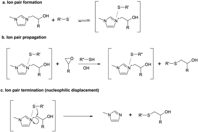
Based on the above considerations, we wondered whether the formation of ion pairs is relevant in nucleophile-catalyzed thiol–epoxy reactions. We propose that some more reactions could be added to those already shown in Scheme 1. To begin with, Scheme 2a shows the hypothetical formation of an ion pair between the β-hydroxylimidazolium and the thiolate. We have illustrated this as an equilibrium because it is acknowledged that the formation and the activity of ion pairs are largely dependent on the possible solvent-ion and solvent-ion pair interactions and the ion concentration,30 and the surrounding environment, with nucleophilic and electrophilic sites, should allow for the presence of “naked” or, rather, non-ion pair forming ions. The propagation of the reaction by this ion pair is illustrated in Scheme 2b, although it is unclear whether this nucleophilic addition should take place on epoxy rings activated by proton donors, like nucleophilic amine–epoxy addition, or else an internal activation with the β-hydroxylimidazolium cation takes place, in line with the mechanism proposed for amine-catalyzed phenol–epoxy reactions.29 Finally, Scheme 2c shows a possible termination reaction by nucleophilic displacement within the ion pair.
The reactivity of ion pairs is complex but it is acknowledged that, in many cases, the presence of ion pairs decreases significantly the rate of ionic polymerization in comparison with free ion systems.30 Rozenberg showed that alkali ions played a complex role in the anionic polymerization of epoxides.17 On the one hand, they could have a positive effect in the activation of the epoxy ring, like proton donors. However, their interaction with propagating alkoxide ions leading to the formation of ion pairs would decrease the propagation rate in comparison with the free alkoxide ions, an effect that was more relevant with increasing size of the alkali ion.17 Ooi et al.24 tested the effect of tetramethyl ammonium chloride (TMAC) on the anionic homopolymerization of epoxides initiated by imidazoles,24 but no effect on the reaction rate could be observed. Given the above considerations,17,30 the propagation of the reaction by this ion pair is supposed to be considerably slower than by the free thiolate anions, and therefore, it might be ruled out from a practical point of view.
The occurrence of the termination reaction proposed in Scheme 2c looks reasonable given the high nucleophilicity of the thiolate anion and the close presence of an electrophilic site within the ion pair, leading to the β-hydroxythioether reaction product and a regenerated imidazole. This reaction, from a kinetic point of view, would be unimolecular, in a similar way to what has been proposed for tertiary amine regeneration in other studies.31–34 In addition, if ion pairs are present in a significant amount in the course of the reaction, this termination mechanism would be presumably more frequent than the bimolecular termination reaction between free ions proposed in Scheme 1d.15
Taking into account all these considerations, different reaction mechanisms based on the reactions shown in Schemes 1 and 2 will be elaborated and their validity will be analyzed by considering their ability to reproduce the experimental results.
3 Materials and methods
3.1 Materials
Diglycidyl ether of bisphenol A (DGEBA) with an epoxy equivalent weight of 172–176 g per eq. (Aldrich), 184–190 g per eq. (Hexion) and 190–210 g per eq. (Huntsman) were dried at 80 °C under vacuum for 2 hours and stored in a desiccator prior to use. These three resins have been coded as DG174, DG187 and DG200, respectively, where the numbers indicate the assumed equivalent weight of the epoxy resin. Trimethylolpropane tris(3-mercaptopropionate) (S3) and 1-methylimidazole (1MI) from Sigma Aldrich were used as received.A set of mixtures using DG174 as an epoxy resin and with different ratios r of thiol groups with respect to epoxy groups were prepared, adding 1 phr (parts per hundred of the total mixture) of 1MI with respect to the total mixture as catalyst. A different set of stoichiometric thiol–epoxy mixtures using DG174 was prepared, adding different proportions of 1MI. Finally, stoichiometric samples with 1 phr of 1MI and changing the epoxy resin were also prepared. The samples were quickly stirred using a spatula and analyzed immediately. Table 1 shows the compositions of the different formulations. The formulations have been coded as DGyyy-r-x where yyy is the epoxy equivalent weight of the epoxy resin, r is the thiol![[thin space (1/6-em)]](https://www.rsc.org/images/entities/char_2009.gif) :
:![[thin space (1/6-em)]](https://www.rsc.org/images/entities/char_2009.gif) epoxy equivalent ratio and x is the 1MI added in phr. It should be mentioned that the thiol equivalent weight was assumed to be the theoretical value of 132.85 g per eq. for the calculation of the composition, although the supplier reports a purity of 98% for this product.
epoxy equivalent ratio and x is the 1MI added in phr. It should be mentioned that the thiol equivalent weight was assumed to be the theoretical value of 132.85 g per eq. for the calculation of the composition, although the supplier reports a purity of 98% for this product.
![[thin space (1/6-em)]](https://www.rsc.org/images/entities/char_2009.gif) :
:![[thin space (1/6-em)]](https://www.rsc.org/images/entities/char_2009.gif) epoxy molar ratio (r) is also included
epoxy molar ratio (r) is also included
| Formulation | r | wt% 1MI | wt% DGEBA | wt% S3 | ee per kg | eqOHDG per kg | eq1MI per ee |
|---|---|---|---|---|---|---|---|
| DG174-1-1 | 1 | 0.99 | 56.18 | 42.83 | 3.227 | 0.0454 | 0.0375 |
| DG174-0.75-1 | 0.75 | 0.99 | 62.99 | 36.02 | 3.618 | 0.0510 | 0.0334 |
| DG174-0.5-1 | 0.5 | 0.99 | 71.68 | 27.33 | 4.118 | 0.0580 | 0.0293 |
| DG174-0.25-1 | 0.25 | 0.99 | 83.16 | 15.85 | 4.778 | 0.0673 | 0.0253 |
| DG174-1.33-1 | 1.33 | 0.99 | 49.06 | 49.95 | 2.820 | 0.0397 | 0.0428 |
| DG174-2-1 | 2 | 0.99 | 39.21 | 59.80 | 2.252 | 0.0317 | 0.0536 |
| DG174-4-1 | 4 | 0.99 | 24.42 | 74.59 | 1.404 | 0.0198 | 0.0860 |
| DG174-1-0.5 | 1 | 0.50 | 56.45 | 43.05 | 3.243 | 0.0457 | 0.0187 |
| DG174-1-2 | 1 | 1.96 | 55.63 | 42.41 | 3.195 | 0.0450 | 0.0748 |
| DG174-1-4 | 1 | 3.85 | 54.55 | 41.60 | 3.134 | 0.0441 | 0.1497 |
| DG187-1-1 | 1 | 0.99 | 57.89 | 41.12 | 3.095 | 0.1853 | 0.0390 |
| DG200-1-1 | 1 | 0.99 | 59.49 | 39.52 | 2.975 | 0.3142 | 0.0406 |
3.2 Characterization techniques
A differential scanning calorimeter Mettler DSC821e calibrated with indium standards was used to study the isothermal curing of the different formulations at 60 °C. Samples of ca. 5–10 mg were placed inside an aluminum pan with a pierced lid and were inserted into a preheated oven before analysis, under a nitrogen atmosphere.The calorimetric degree of conversion was determined as x = Δh/Δhtotal, where Δh is the reaction heat released up to a time t and Δhtotal is the total reaction heat evolved. The calorimetric reaction rate was determined as dx/dt = (dh/dt)/Δhtotal, where dh/dt is the heat flow. Taking into account the thiol–epoxy ratio r of the different formulations, an approximate conversion of epoxy groups, xe,DSC, was calculated from the experimental DSC data as:
A rate of conversion of epoxy groups dxe,DSC/dt could also be estimated from the calorimetric data as:
3.3 Kinetic modelling
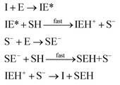
where I is the initiator, E is the epoxy ring, IE* is the zwitterion formed after initiation, SH is a thiol group, IEH+ is the hydroxyl-ammonium cationic species formed by proton transfer from the thiol group, S− is the propagating thiolate anion, SE− is the alkoxide formed after thiolate addition, and SEH is the reaction product of the thiol–epoxy addition.
The initiation step leading to the formation of the zwitterion IE* and the thiolate addition to the epoxy ring can be catalyzed by proton donors, such as hydroxyl groups already present or formed in the course of the reaction.16,21
Loureiro et al. modelled this catalytic effect by assuming the formation of an epoxy–hydroxyl equilibrium complex prior to the nucleophilic addition,15 following other studies.35,36 The effect of equilibrium complexes is a common issue in reacting systems such as epoxy–amine.17,37–40 However, hydroxyl-catalyzed nucleophilic addition of amines to epoxy groups is commonly modelled in a more simplified way by not considering the presence of such complexes: a trimolecular reaction between epoxy, amine and the catalytic hydroxyl group is assumed instead.41,42 Jin et al. modelled the base-catalyzed curing of thiol–epoxy formulations using phenomenological models and interpreted the fitted parameters quite convincingly assuming a simplified version of the catalyzed nucleophilic addition,16 like in epoxy–amine systems. This interpretation should be safe if the epoxy–hydroxyl equilibrium constant was low enough, leading to a reduced error.36 However, in the present case the system is more complex since we have performed nucleophilic addition of both the initiator and the thiolate to the epoxy groups. The presence of catalytic impurities in the reagents as well as the absorption of some humidity from the environment during preparation could make it difficult to identify all the possible intermediate complexes. In such situations, the effect of impurities is taken into consideration in a simplified manner.17 Therefore, for the sake of simplicity, in the present model we assume that this somewhat inaccurate representation of the catalytic effect of hydroxyl groups provides a reasonable description of the effect.
Therefore, the basic reaction mechanism can be represented as follows in terms of rate equations (basic kinetic model):
Note that the total number of thiol/thiolate species is defined as [SH]total = [SH] + [S−] and that the total amount of potentially active species is defined as [IE]total = [IE*] + [IEH+]. In the course of the reaction, while [SH]total > [IE]total, the number of active propagating species is [S−] = [IEH+] = [IE]total, and [IE*] ≈ 0. However, when the reaction reaches completion, it may be that [SH]total < [IE]total, so that [S−] = [IEH+] = [SH]total and [IE*] = [IE]total − [SH]total.
In order to take into account the effect of the catalytic groups already coming from the reagents or hypothetical impurities, as well as the formed hydroxyl groups by reaction, we have defined the initiation and propagation constants, ki and kp, as follows:
| ki = ki,DG·[OH]DG + ki,SH·[SH]0 + ki,cat·([SEH] + [IEH+]) |
| kp = kp,DG·[OH]DG + kp,SH·[SH]0 + kp,cat·([SEH] + [IEH+]) |
The different contributions to the initiation constant come from the presence of hydroxyl groups in the oligomeric structure of DGEBA, [OH]DG, impurities contained in the thiol crosslinking agent that are assumed to be proportional to the initial concentration of thiol groups [SH]0, and catalytic species formed in the course of the reaction, [SEH] + [IEH+]. The contribution of the hydroxyl–thioether and the hydroxylammonium cation should be different but, for the sake of simplicity, we have grouped them together.
It is quite common to model reaction kinetics using normalized concentrations rather than real concentrations,34,42 so that the normalized concentration of a species A can be calculated with respect to the initial concentration of epoxy groups, so that a = [A]/[E]0. This makes it possible to define a set of kinetic reactions in terms of the normalized species, but the kinetic constants need to be redefined.34,42 The details of such transformations are shown in the Appendix.
| I + E → IE* |
| IEH+ + S− ⇄ IEH+S− |
| S− + E → SE− |
| IEH+S− → I + SEH |
In this set of reactions, we define:
| [IE]total = [IE*] + [IEH+] + [IEH+S−] |
| [SH]total = [SH] + [S−]total = [SH] + [S−] + [IEH+S−] |
Also, one should consider that:
| [S−]total = [S−] + [IEH+S−] = [IEH+] + [IEH+S−] |
In the course of the reaction, while [SH]total > [IE]total, the number of active propagating species is [S−]total = [IE]total with [IE*] = 0. When the reaction reaches completion, it may be that [SH]total < [IE]total, so that [S−]total = [SH]total and [IE*] = [IE]total − [SH]total. The real amount of propagating thiolate and ion-pair species, [S−] and [IEH+S−], are found by solving the equilibrium in any case.
In order to take into account the catalytic effect of the different species on the initiation and propagation rates, the initiation and propagation constants are defined exactly the same way as before. As in the previous model, the reaction kinetics is also analyzed making use of normalized concentrations of the different species (see Appendix).
| xe = 1 − e |
where xe,max is the maximum epoxy conversion calculated by the kinetic model. The rate dxe,DSC/dt can also be determined from the results of the kinetic model as:
where de/dt is the normalized reaction rate of epoxy groups (see the Appendix).
The integration is performed simultaneously for all the compositions indicated in Table 1 and the kinetic constants and equilibrium constants, ki,DG, ki,SH, ki,cat, kp,DG, kp,SH, kp,cat, kt, keq,IP and kt,IP are fitted using a nonlinear regression procedure with the following minimization function:
4 Results and discussion
4.1 Experimental results
Fig. 1 shows the experimental rate curves that were obtained from the isothermal curing at 60 °C for all the formulations. If one compares these results with those reported by Jin et al.,16 some relevant differences between commonly used basic catalysts and nucleophilic catalysts can be highlighted. In base-catalyzed thiol–epoxy reactions, the reaction starts immediately after the reagents are mixed and, because of the strong autocatalysis of the reaction, it can become difficult to control. Note that in a recent study by Jin et al.16 the authors used DBU as the base catalyst in a concentration of just 0.17% with respect to the concentration of thiol groups. In contrast, Fig. 1 shows that the reaction onset is delayed using a nucleophilic initiator such as 1MI, as observed in the studies of Loureiro et al.15 and our recent study on dual-curable off-stoichiometric thiol–epoxy formulations.6 This may not be regarded as a truly latent behavior, but nevertheless it suggests it is safer to prepare and control their curing process using nucleophilic initiators rather than basic catalysts, which could be highly useful in terms of processing. This is a similar phenomenon to what has been reported for Michael addition reactions using specific nucleophilic catalysts.43,44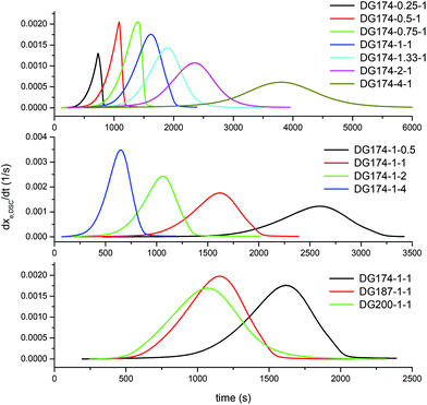 | ||
| Fig. 1 Experimental rate curves illustrating the effect of the thiol–epoxy ratio (top graph), initiator content (middle graph) and epoxy equivalent weight (bottom graph). | ||
A closer examination of Fig. 1 reveals a number of significant features of nucleophile-initiated thiol–epoxy reactions. In the top graph, the effect of the thiol–epoxy ratio r is illustrated. At lower thiol–epoxy ratios, the curve starts earlier because of the increasing concentration of epoxy groups and a subsequent enhancement in the rate of the initiation step, consisting of the nucleophilic addition of 1MI to the epoxy ring. An additional accelerating effect coming from the increasing concentration of the initial catalytic hydroxyl groups present in the formulation (see Table 1) is also expected. The formulations with thiol–epoxy ratios lower than 1 also show a strong autoacceleration just before a sharp decrease in the reaction rate that coincides with the exhaustion of the available thiol groups, in agreement with previously reported data.6 The formulations with a thiol–epoxy ratio higher than one show a slower activation and reaction rate due to the decrease in the concentration of the available epoxy groups and catalytic hydroxyl groups coming from the structure of DG174 (see Table 1). In all the formulations with r < 1, at the end of the reaction there remain unreacted epoxy groups, while at r ≥ 1, a complete conversion of epoxy groups is achieved.
In the middle graph, the effect of the initiator content is shown for stoichiometric formulations using DG174 as epoxy resin. As expected, there is a clear trend of the decreasing reaction onset and increasing reaction rate with increasing initiator content. However, the effect is not apparently proportional to the initiator content (see Table 1). The bottom graph shows the effect of increasing the epoxy equivalent weight of the DGEBA and, with this, the content in catalytic hydroxyl groups coming from the oligomeric structure of DGEBA. The effect is apparently complex. It can be observed that increasing the epoxy equivalent weight leads to an earlier initiation of the reaction in spite of the decreasing concentration of epoxy groups in the formulation, because of the increasing concentration of oligomeric hydroxyl groups (see Table 1). The difference between the formulations containing DG187 and DG200 is not very significant, possibly because of this trade-off.
All these observations illustrate the complexity of the nucleophile-initiated thiol–epoxy addition. The basic and complex models, based on mechanistic considerations, are tested and their validity is discussed.
4.2 Analysis of the kinetic models
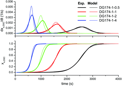
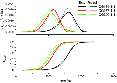
First of all, we analyze the validity of the basic kinetic model inspired by the mechanism proposed by Loureiro et al.15 The fitted parameters are shown in Table 2. The experimental data and model predictions are compared in Fig. 2 for the effect of the thiol–epoxy ratio, in Fig. 3 for the effect of the catalyst content and in Fig. 4 for the effect of the epoxy equivalent weight. As can be seen in the figures, the model is capable of reproducing, at least from a qualitative point of view, the expected behaviour in terms of reaction rate and reaction onset: it includes both the effect of the nucleophilic initiation and the exhaustion of thiol groups in formulations with r < 1, and takes into consideration the autocatalytic behaviour of the reaction. The average error is 60.5 seconds, as seen in Table 2, although individual errors are quite substantial in some cases. The model produces an exceedingly high delay in the predicted reaction of formulations with r < 1 (Fig. 2) and overestimates the effect of the thiol–epoxy ratio r (Fig. 2) on the peak reaction rate. The effect of the catalyst content on the overall reaction time is well predicted, but it overestimates its effect on the peak reaction rate (Fig. 3). The kinetic model predicts quite well the effect of the epoxy equivalent weight (Fig. 4), but the reaction rates are overestimated in the case of the DG174-1-1 and DG200-1-1 formulations. Although valid as a first approximation, this model does not accurately reproduce the shape of the different curing processes. Therefore, the underlying reaction mechanism must be different from that represented in this kinetic model.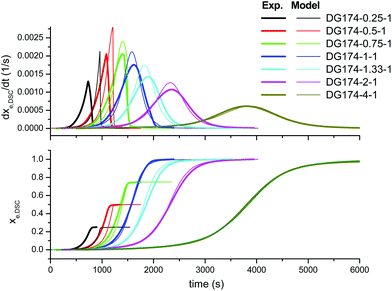 | ||
| Fig. 2 Comparison between the predictions of the basic kinetic model and the experimental data, the effect of the thiol–epoxy ratio, using the parameters in Table 2. | ||
 | ||
| Fig. 3 Comparison between the predictions of the basic kinetic model and the experimental data, the effect of the initiator content, using the parameters in Table 2. | ||
 | ||
| Fig. 4 Comparison between the predictions of the basic kinetic model and the experimental data, the effect of the DGEBA epoxy equivalent weight, using the parameters in Table 2. | ||
| Basic | Complex | |
|---|---|---|
| k i,DG (M−2 s−1) | 5.725 × 10⁻⁴ | 5.460 × 10⁻⁴ |
| k i,SH (M−2 s−1) | 1.729 × 10⁻⁶ | 1.608 × 10⁻⁶ |
| k i,cat (M−2 s−1) | 1.962 × 10⁻³ | 3.652 × 10⁻³ |
| k p,DG (M−2 s−1) | 3.712 × 10⁻⁴ | 9.462 × 10⁻⁴ |
| k p,SH (M−2 s−1) | 7.727 × 10⁻⁵ | 7.272 × 10⁻⁶ |
| k p,cat (M−2 s−1) | 2.386 × 10⁻² | 3.200 × 10⁻² |
| k t (M−1 s−1) | 3.712 × 10⁻² | 0 |
| k eq,IP (M−1) | 0 | 13.41 |
| k t,IP (s−1) | 0 | 8.950 × 10⁻³ |
| Error (s) | 60.5 | 50.2 |
In order to improve the quality of the fitting, the complex model, based on other mechanistic considerations, was tested. Fig. 5 shows the effect of the thiol–epoxy ratio, Fig. 6 shows the effect of the initiator content and Fig. 7 shows the effect of the epoxy equivalent weight. The fitted kinetic parameters and the error are shown in Table 2. The error of the adjustment is lower, only 50.2 seconds, and an inspection of the curves confirms that the quality of the fitting process is much better. Indeed, Fig. 5 shows that the effect of the thiol–epoxy ratio on the reaction rate is little overestimated, differences being most noticeable at the lowest thiol–epoxy ratios, 0.5 and, especially, 0.25. Although the model still predicts a slower initiation in these cases, the adjustment is significantly better. Fig. 6 shows that the effect of the catalyst content is now nicely predicted by the model. The effect of the epoxy equivalent weight is also quite well reproduced, as shown in Fig. 7, with some discrepancies in the case of the intermediate DG187-1-1 formulation.
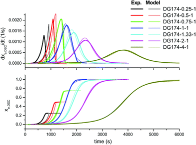 | ||
| Fig. 5 Comparison between the predictions of the complex kinetic model and the experimental data, the effect of the thiol-epoxy ratio, using the parameters in Table 2. | ||
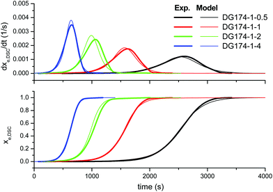 | ||
| Fig. 6 Comparison between the predictions of the complex kinetic model and the experimental data, the effect of the initiator content, using the parameters in Table 2. | ||
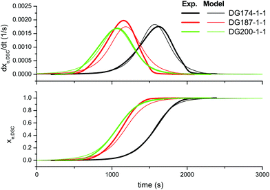 | ||
| Fig. 7 Comparison between the predictions of the complex kinetic model and the experimental data, the effect of the DGEBA epoxy equivalent weight, using the parameters in Table 2. | ||
An indirect confirmation of these results could be made from a comparison between the rate constants obtained and those found in the literature. Unfortunately, the adjustment procedure in the work of Loureiro et al.15 makes it difficult to compare their results with ours. Therefore, the only data we can use are from the work of Jin et al.16 These authors fitted the experimental data to a phenomenological Kamal model, with dx/dt = (k1 + k2·xm)·(1 − x)n, and interpreted the parameters in terms of the reaction mechanism. For a stoichiometric formulation using a trifunctional thiol and an epoxy monomer of a low epoxy equivalent weight (180 g mol−1), cured at 60 °C with 0.17 mol% of DBU, they obtained k1 = 0.77 × 10⁻⁵ s−1, k2 = 0.65 × 10⁻³ s−1, and m = n = 1. The values of the m and n parameters, which were about the same at all temperatures, were in excellent agreement with a base-catalyzed reaction mechanism, with the same assumptions that we made in this work concerning the activation of the epoxy ring by proton donors. Assuming that strong bases such as DBU produce the maximum amount of active species from the very beginning, and that an ion-pair such as the one in this work would not be formed (or present much weaker interactions), their value of k2 should be equivalent to our value of kp,cat·[E0]2·i, for an equivalent thiol–epoxy formulation. The value of i should be the molar concentration of DBU the authors used in their work,16 0.0017 mol DBU per mol of SH groups. The calculated value of k’p,cat·i0 is equal to 0.75 × 10⁻³ s−1, only 15% higher than k2. While k1 should be equivalent to (kp,DG·ohDG + kp,SH·sh0)·[E0]2·i, our calculation yields a value of 10–6 s−1, which is about 8 times lower. Comparison of k2 with kp,cat·[E0]2·i should be more reliable because of the strong autocatalytic component of the reaction, which is due to the generation of a hydroxyl group per each epoxy/thiol group reacted. However, comparison between k1 and (kp,DG·ohDG + kp,SH·sh0)·[E0]2·i depends largely on the presence of catalytic impurities in the reaction medium, often coming from the use of industrial grade products. It should be considered that the results from our analysis are obtained from a numerical fitting of the data to a model with a significant number of parameters, which may involve uncertainties stemming from the numerical method. Added uncertainty comes from the fact that the reaction starts by nucleophilic attack of 1MI to the epoxy ring, which is highly sensitive to catalytic groups and impurities present in the system, and this might conceal the effect of such impurities on the propagation rate.
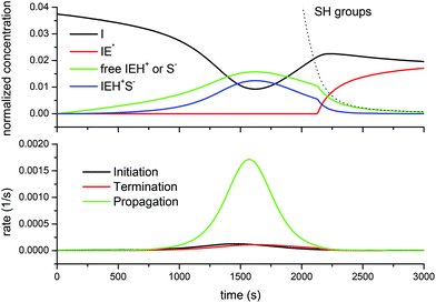
At this point, it is also good to analyze the distribution of the relevant species (other than epoxy and thiol groups) in the course of the reaction, and the contribution of the different rates of initiation, propagation and termination to the overall reaction rate.
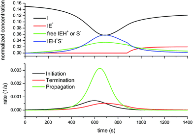
Fig. 8 shows the situation for the DG174-1-1 formulation. It is noteworthy that, as the reaction starts, the growing concentration of free thiolate anions does not start the reaction immediately. When the propagation rate starts to increase, an increase in the concentration of active species is noted, but this is offset by the formation of the ion-pair, which moderates the amount of free thiolate propagating the reaction. The amount of active species reaches a maximum around the maximum propagation rate because the decreasing concentration of the epoxy groups and initiator I leads to a decreasing initiation rate. At this point, about 75% of the initiator has been converted into IEH+ species (free and ion-pair). In consequence, the concentration of the free initiator starts to increase again. A change in the trend is observed once the concentration of the thiol groups falls below a certain threshold, so that the amount of active species is no longer controlled by the total reacted initiator but by the availability of the thiol groups to produce free thiolate anions. At this point, the concentration of the inactive (or rather less active) zwitterion IE*, which was 0 (or nearly) because of the presence of a sufficient amount of thiol groups leading to a fast proton transfer to produce thiolates, starts to increase as well. The absence of the zwitterion IE*, in addition to its low reactivity, justifies the absence of epoxy homopolymerization, so that in the presence of thiol groups only the thiol–epoxy addition takes place. At the end of the process a significant amount of the unreacted initiator I remains, which is in good agreement with the experimental results of Loureiro et al.,15 who showed that, at the end of the thiol–epoxy addition, there was a significant amount of the unreacted initiator in the SEC traces of the reaction product. Throughout the curing process the contribution of the initiation and termination reactions to the reaction rate is very small in comparison with the propagation, due to the small concentration of the initiator and active species available.
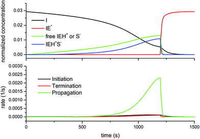
Fig. 9 shows the same results but for the DG174-1-4 system, with four times more catalyst. The shape of the curves is pretty much the same as in the previous case, but there is a relevant difference in the relative contribution of the free IEH+ or thiolate species and the ion-pair. The larger concentration of total active species promotes the formation of the ion-pair, to the detriment of the free thiolate anion propagating the reaction. Thus, it is no surprise that the ion-pair concentration becomes larger than the concentration of free thiolate. When Fig. 8 and 9 are compared, it can be observed that the maximum concentration of thiolate anions is slightly more than double when 4 phr of 1MI are used in comparison with 1 phr of 1MI. Another relevant difference between both figures is that the initiation rate contributes more heavily to the overall reaction rate in the presence of 4 phr of 1MI, which could be expected. At the end of the reaction process, as the thiol groups are exhausted, there is a non-negligible amount of the zwitterion formed.
Finally, Fig. 10 shows the evolution of the different species and rates for the off-stoichiometric DG174-0.5-1 formulation. The model predicts that, due to the exhaustion of thiol groups, the concentration of the free thiolate and ion-pair decreases sharply. However, because there is a significant excess of epoxy groups, this takes place near the peak in the reaction rate, leading to a sharp decrease in the overall reaction rate altogether. At this point, the amount of the zwitterion starts to increase as well. However, because of the presence of the remaining epoxy groups and the high concentration of catalytic hydroxyl groups formed in the course of the reaction, the initiation continues at a fast rate and leads to a depletion of initiator species and the formation of the maximum possible amount of the zwitterion. This zwitterion is the species that would start the propagation of the epoxy homopolymerization, but this species would be more stable and less active than other alkoxide anions, as commented above. According to Heise and Martin, the adduct formation would reach completion before the homopolymerization process starts.18,19 According to the model, this species would be ready at the end of the thiol epoxy process, so that the homopolymerization process would eventually start if one waited for long enough or increased the temperature.6 It should be noted that for the curing of a formulation with excess thiol groups (results not shown), throughout the whole curing process and at the end of it there would not be any traces of this zwitterion species.
In the light of these results, it appears that the hypotheses behind the proposed complex kinetic model, involving the presence of the non-reactive ion-pair in the reaction medium, become quite realistic. The main features of the curing process and the rates and reaction onsets are well reproduced by the model. The effect of the composition on the reaction rate is also accounted for by the model. Indeed, if one compares the values of ki,DG, ki,SH, kp,DG and kp,SH as in Table 2, and considering the way these constants were defined (see section 3.3), it can be deduced that the effect of catalytic impurities in the thiol monomer (i.e. hydroxyl groups) on the initiation and propagation rate constants is indeed lower than that of the epoxy monomer, but not negligible. The values of ki,cat and kp,cat also indicate that the catalytic effect of the reaction product is significantly stronger, in agreement with the results of Loureiro et al.15 The model still overestimates the reaction onset in formulations with thiol–epoxy ratios lower than one, but this might be a consequence of both inaccuracies inherent to the reaction mechanism and experimental error caused by the fast initiation of these formulations. In any case, assuming that the distribution of reactive species produced by this model is right, it could be used to analyze the crosslinking process of stoichiometric or off-stoichiometric thiol–epoxy formulations, rather than relying only on ideal step-wise assumptions.6 In addition, the model could be extended to study the reaction processes of thiol–epoxy systems initiated by other nucleophilic tertiary amines,15 but obviously the values of the model constants would be different, especially those connected with the amine structure and reactivity such as the initiation and termination rate constants as well as the ion-pair equilibrium constant.
We acknowledge that the model has some inaccuracies and simplifications that might be addressed in future studies. Whether the termination is a unimolecular rearrangement of the ion-pair or a bimolecular reaction between free thiolate and hydroxylammonium cation species makes no practical difference. We assumed that the propagation by means of the ion-pair species was negligible for the sake of simplicity, but one might consider some reactivity of the ion-pair towards propagation. The initiating mechanism based on the nucleophilic attack of the imidazole to the epoxy ring should be re-analyzed. Nucleophilic addition of amines to epoxy groups can be quite complex, as reported for epoxy–amine systems.35–38,40 The formation of multiple equilibrium complexes complicates significantly the apparently simple autocatalytic epoxy–amine addition. When several equilibrium complexes, some of which are active, are present at the same time, the real amount of active species is reduced and, if this effect is neglected, the reaction rate is overestimated.40 A similar consequence could be expected for the initiation step between the imidazole and the epoxy ring. The initiation step in epoxy–imidazole systems is highly sensitive to the chemical environment, not only due to the presence of catalytic species17,21 but also to the formation of unreactive complexes in the presence of polyethers,45 like in epoxy–amine systems.40 Nevertheless, in the absence of more detailed experimental information (i.e. the individual determination of some rate or equilibrium constants), the inclusion of a larger number of fitting parameters would complicate the interpretation of the results. We already tested the effect of the epoxy–hydroxyl complexes, but we found that the complex equilibrium constant was very low (results not shown), so that our simplification of the catalytic effect could be considered as a safe one, in line with the results of Jin et al.16 and in agreement with the reasoning of Flammersheim,36 although this might also be a side consequence of the mathematical fitting process. In multiple non-linear regression modelling of complex processes there could be more than one solution, given that the optimum point might be within a flat hollow rather than a deep valley of the solution space,37 or else a number of local minima with a similar error could be easily found. In order to refine the proposed model, taking into account the above considerations, more experimental work should be carried out in order to investigate in more depth the effect of the chemical environment on the initiation step and the role of the ion-pair equilibrium complex, as well as the effect of temperature on the different kinetic parameters, so as to produce a more consistent model and a more meaningful set of kinetic parameters.
5 Conclusions
The thiol–epoxy addition reaction initiated by tertiary amines has been analyzed from theoretical and experimental points of view. DGEBA and S3 have been used as epoxy and thiol compounds, and 1MI has been used as the nucleophilic tertiary amine initiator. The effects of the thiol–epoxy ratio, epoxy equivalent weight and initiator content have been taken into consideration.The reaction takes place earlier in formulations richer in epoxy monomers because of the initiation by the nucleophilic attack of the tertiary amine to the epoxy group and the contribution of catalytic hydroxyl groups in the epoxy oligomer. The end of the reaction is sharp in formulations with excess of epoxy groups due to the exhaustion of thiol groups and transfer of the thiolate active species to a less active zwitterion species that would propagate the homopolymerization of the excess epoxy groups. Increasing the initiator content does not increase proportionally the propagation and initiation rates. The use of epoxy monomers with higher epoxy equivalent weights leads to faster reactions because of the catalytic effect of the hydroxylic epoxy oligomers, in spite of the reduced concentration of epoxy groups.
A kinetic model based on an approximate reaction mechanism for the thiol–epoxy reaction initiated by tertiary amines has been defined. This model satisfactorily reproduces all the phenomena associated with the curing process of stoichiometric and off-stoichiometric thiol–epoxy mixtures initiated by 1MI, and it is hypothesized it could be extended, with obviously different values of the parameters, to thiol–epoxy systems initiated by other nucleophilic tertiary amines. A complete validation of the model would require, however, the analysis of the effect of different curing temperatures under isothermal and nonisothermal reaction conditions, producing a more consistent and meaningful set of kinetic parameters.
One of the most remarkable features of the model is the assumption of the presence of a less-reactive ion-pair complex in equilibrium with free thiolate and cationic species, making it possible to predict correctly the effect of changing the initiator content and thiol–epoxy ratio on the reaction rate. However, the understanding of the exact role of the ion-pair in the reaction medium in terms of reactivity requires further investigation. The model also attempts, in a simplified way, to describe separately the catalytic effects of hydroxyl groups and other impurities present in the epoxy resin and in the thiol crosslinker, and the hydroxyl groups present in the reaction product. However, it is acknowledged that the model is not accurate enough in that respect. Among other issues, one should consider the formation of different active and non-active complexes depending on the presence of different catalytic or deactivating species. Proper elucidation of the initiation step, which is crucial for the understanding of the reactivity of these systems, remains therefore a pending task.
Conflicts of interest
There are no conflicts to declare.Appendix
Basic kinetic model
In terms of the normalized concentration of the different species, the basic set of rate equations transforms into:where
| shtotal = sh + s− |
| ietotal = ie* + ieh+ |
The number of propagating species is calculated as:
Because of the normalization process, the kinetic and equilibrium constants are now expressed as:
| k′t = kt·[E]0 |
An implicit assumption here is that the volume changes during curing are negligible. If one were to consider the volume changes, the expressions should be modified in a convenient way.34
Complex kinetic model
In terms of normalized concentrations, the rate and equilibrium expressions of the complex model take the following form:In this set of reactions, we define:
| ietotal = ie* + ieh+ + ieh+s− |
| shtotal = sh + s−total = sh + s− + ieh+s− |
One should also consider that:
| s−total = s− + ieh+s− = ieh+ + ieh+s− |
The number of potentially active species is determined as:
Having determined s−total, the ion-pair equilibrium is solved as:
The normalized propagation and initiation constants k′i and k′p are defined in the same way as in the basic model. The equilibrium and termination constants of the ion-pair are defined as:
| k′eq,IP = keq,IP·[E]0 |
| k′t,IP = kt,IP |
Initial concentration of reactive species
Taking into account the weight fraction of each component specified in Table 1, the initial concentrations of the epoxy and initiator groups were calculated as:where wDG and wMI are the weight fractions of the epoxy monomer and initiator in the mixture (the values in Table 1 divided by 100), and eqMI is the equivalent weight of 1MI and assumed to be 82 g mol−1. The density ρ has been estimated from the composition of the formulations and the density of the pure compounds at room temperature assuming the additivity of volumes and correcting the density to the curing temperature using the approximation of Van Krevelen for oligomers or polymers above their glass transition temperature.34,46
With [E]0 and [I]0, one can determine the initial normalized concentrations for the integration of the rate equations:
| \eqalign{ \tab e0 = 1 sh0 = shtotal,0 = r·fSH i0 = [I]0/[E]0 ietotal,0 = 0 \cr \tab seh0 = 0 |
In the expression for the normalized initial concentration of thiol groups sh0, r is the theoretical thiol–epoxy ratio used for the calculation of the mixture composition, and fSH represents the purity of the thiol monomer and takes a value of 1 for a perfectly pure reagent, but in this case takes a value of 0.98 according to the product specifications.
The initial amount of hydroxyl groups coming from DGEBA, ohDG is approximately calculated from the epoxy equivalent weight, eqDG, as:
The initial concentration of all the other species in the basic or complex models is initially equal to 0.
Acknowledgements
The authors would like to thank MINECO (MAT2014-53706-C03-02) and Generalitat de Catalunya (2014-SGR-67 and Serra Húnter programme) for financial support.References
- C. E. Hoyle, A. B. Lowe and C. N. Bowman, Chem. Soc. Rev., 2010, 39, 1355–1387 RSC
.
- J. A. Carioscia, J. W. Stansbury and C. N. Bowman, Polymer, 2007, 48, 1526–1532 CrossRef CAS PubMed
.
- C. F. Carlborg, A. Vastesson, Y. Liu, W. van der Wijngaart, M. Johansson and T. Haraldsson, J. Polym. Sci., Part A: Polym. Chem., 2014, 52, 2604–2615 CrossRef CAS
.
- F. Saharil, F. Forsberg, Y. Liu, P. Bettotti, N. Kumar, F. N. Haraldsson, W. v. derWijngaart and K. B. Gylfason, J. Micromech. Microeng., 2013, 23, 025021 CrossRef
.
- D. Guzman, X. Ramis, X. Fernandez-Francos and A. Serra, RSC Adv., 2015, 5, 101623–101633 RSC
.
- X. Fernandez-Francos, A.-O. Konuray, A. Belmonte, S. De la Flor, A. Serra and X. Ramis, Polym. Chem., 2016, 7, 2280–2290 RSC
.
- M. Sangermano, A. Vitale and K. Dietliker, Polymer, 2014, 55, 1628–1635 CrossRef CAS
.
- C. Seubert and M. Nichols, J. Coat. Technol. Res., 2010, 7, 615–622 CrossRef CAS
.
- D. Guzmán, X. Ramis, X. Fernández-Francos and A. Serra, Eur. Polym. J., 2014, 59, 377–386 CrossRef
.
- D. Guzmán, X. Ramis, X. Fernández-Francos and A. Serra, Polymers, 2015, 7, 680–694 CrossRef
.
- D. Guzmán, B. Mateu, X. Fernández-Francos, X. Ramis and A. Serra, Polym. Int., 2017 DOI:10.1002/pi.5336
.
- J. Shin, H. Matsushima, C. M. Comer, C. N. Bowman and C. E. Hoyle, Chem. Mater., 2010, 22, 2616–2625 CrossRef CAS
.
- H. Salmi, X. Allonas, C. Ley, A. Defoin and A. Ak, Polym. Chem., 2014, 5, 6577–6583 RSC
.
- A. O. Konuray, X. Fernández-Francos and X. Ramis, Polymer, 2017, 116, 191–203 CrossRef CAS
.
- R. M. Loureiro, T. C. Amarelo, S. P. Abuin, E. R. Soulé and R. J. J. Williams, Thermochim. Acta, 2015, 616, 79–86 CrossRef CAS
.
- K. Jin, W. H. Heath and J. M. Torkelson, Polymer, 2015, 81, 70–78 CrossRef CAS
.
- B. A. Rozenberg, Adv. Polym. Sci., 1986, 75, 113–165 CrossRef
.
- M. S. Heise and G. C. Martin, Macromolecules, 1989, 22, 99–104 CrossRef CAS
.
- M. S. Heise and G. C. Martin, J. Appl. Polym. Sci., 1990, 39, 721–738 CrossRef CAS
.
- J. M. Barton, I. Hamerton, B. J. Howlin, J. R. Jones and S. Liu, Polym. Int., 1996, 41, 159–168 CrossRef CAS
.
- X. Fernandez-Francos, W. D. Cook, A. Serra, X. Ramis, G. G. Liang and J. M. Salla, Polymer, 2010, 51, 26–34 CrossRef CAS
.
- M. H. Abraham, P. P. Duce, D. V. Prior, D. G. Barratt, J. J. Morris and P. J. Taylor, J. Chem. Soc., Perkin Trans. 2, 1989, 1355–1375 RSC
.
- M. S. Heise, G. C. Martin and J. T. Gotro, J. Appl. Polym. Sci., 1991, 42, 1557–1566 CrossRef CAS
.
- S. K. Ooi, W. D. Cook, G. P. Simon and C. H. Such, Polymer, 2000, 41, 3639–3649 CrossRef CAS
.
- F. Ricciardi, W. A. Romanchick and M. M. Joullie, J. Polym. Sci., Polym. Chem. Ed., 1983, 21, 1475–1490 CrossRef CAS
.
- S. Han, H. Gyu Yoon, K. S. Suh, W. Gun Kim and T. Jin Moon, J. Polym. Sci., Part A: Polym. Chem., 1999, 37, 713–720 CrossRef CAS
.
-
R. W. Biernath and D. S. Soane, in Advances in New Materials, Springer US, Boston, MA, 1992, pp. 103–159 Search PubMed
.
- Y.-C. Chen, W.-Y. Chiu and K.-F. Lin, J. Polym. Sci., Part A: Polym. Chem., 1999, 37, 3233–3242 CrossRef CAS
.
-
S. Lin-Gibson and J. S. Riffle, in Synthetic Methods in Step-Growth Polymers, John Wiley & Sons, Inc., 2003, pp. 375–430 Search PubMed
.
-
M. Szwarc, in Pure and Applied Chemistry, 1976, vol. 48, p. 247 Search PubMed
.
- A. N. Mauri, N. Galego, C. C. Riccardi and R. J. J. Williams, Macromolecules, 1997, 30, 1616–1620 CrossRef CAS
.
- C. C. Riccardi, J. Dupuy and R. J. J. Williams, J. Polym. Sci., Part B: Polym. Phys., 1999, 37, 2799–2805 CrossRef CAS
.
- X. Fernandez-Francos, Eur. Polym. J., 2014, 55, 35–47 CrossRef CAS
.
- X. Fernandez-Francos, X. Ramis and A. Serra, J. Polym. Sci., Part A: Polym. Chem., 2014, 52, 61–75 CrossRef CAS
.
- C. C. Riccardi, F. Fraga, J. Dupuy and R. J. J. Williams, J. Appl. Polym. Sci., 2001, 82, 2319–2325 CrossRef CAS
.
- H. J. Flammersheim, Thermochim. Acta, 1997, 296, 155–159 CrossRef CAS
.
- H. J. Flammersheim, Thermochim. Acta, 1998, 310, 153–153 CrossRef CAS
.
- S. Swier, G. Van Assche and B. Van Mele, J. Appl. Polym. Sci., 2004, 91, 2814–2833 CrossRef CAS
.
- S. Swier, G. Van Assche and B. Van Mele, J. Appl. Polym. Sci., 2004, 91, 2798–2813 CrossRef CAS
.
- S. Swier, G. Van Assche, W. Vuchelen and B. Van Mele, Macromolecules, 2005, 38, 2281–2288 CrossRef CAS
.
- K. C. Cole, Macromolecules, 1991, 24, 3093–3097 CrossRef CAS
.
- E. Girard-Reydet, C. C. Riccardi, H. Sautereau and J. P. Pascault, Macromolecules, 1995, 28, 7599–7607 CrossRef CAS
.
- J. W. Chan, C. E. Hoyle, A. B. Lowe and M. Bowman, Macromolecules, 2010, 43, 6381–6388 CrossRef CAS
.
- S. Chatani, R. J. Sheridan, M. Podgorski, D. P. Nair and C. N. Bowman, Chem. Mater., 2013, 25, 3897–3901 CrossRef CAS
.
- K.-L. Chen, Y.-H. Shen, M.-Y. Yeh and F. F. Wong, J. Taiwan Inst. Chem. Eng., 2016, 43, 306–312 CrossRef
.
-
D. W. Van Krevelen, Properties of polymers: their correlation with chemical structure, their numerical estimation and prediction from additive group contributions/by D.W. van Krevelen, 1990 Search PubMed
.
| This journal is © The Royal Society of Chemistry 2017 |

