 Open Access Article
Creative Commons Attribution 3.0 Unported Licence
Janus nanoparticles inside polymeric materials: interfacial arrangement toward functional hybrid materials
Qiuyan
Yang
and
Katja
Loos
 *
*
Macromolecular Chemistry & New Polymeric Materials, Zernike Institute for Advanced Materials, University of Groningen, Nijenborgh 4, 9747 AG Groningen, The Netherlands. E-mail: k.u.loos@rug.nl
First published on 17th November 2016
Abstract
Control of the location and spatial organization of nanoparticles (NPs) inside polymers is essential to generate highly ordered NP-based functional devices including plasmonic waveguides, photonic crystals, optical lenses, memory storage devices, nanoelectronic circuits, photovoltaics, and batteries. Due to the unique combination of amphiphilicity and the particle character, Janus nanoparticles (JNPs) show high interfacial activity at fluid–fluid interfaces and in the bulk (for example, polymer blends and block copolymers (BCPs)). Interfacial incorporation of Janus NPs inside a polymeric matrix can endow polymeric materials with improved mechanical and additional properties from ordinary NPs. Here, different from other reports providing general overviews on the synthesis and applications of JNPs, this review specifically highlights recent advances and success in interfacial behavior of Janus NPs at polymer interfaces. We hope that these accomplishments will motivate additional efforts in large-scale synthesis and interfacial behavior studies of Janus NPs in polymer matrices allowing the design of functional hybrid nanostructures and devices with engineered, desired and tailored properties for real-life applications.
1. Introduction
Incorporating nanoparticles (NPs) into polymeric materials is not only a practical pathway to develop engineered plastics with increased mechanical, optical, electrical, magnetic, and other properties. This technique is also one of the most attractive ways to obtain well-defined structures at different length scales by controlling the spatial organization of NPs inside polymers. The term “polymer–nanoparticle nanocomposites” has already been applied since the early 20th century but just attracted broad interest until the 1990s.1,2 In the past 20 years, in order to be able to produce nanocomposites for practical use with engineered, desired, and tailored properties, extensive effort has been made to comprehensively understand the structure–property relationship in the polymer–NP mixture.3–13One consensus is that control of the location and spatial organization of NPs inside polymers is essential for generating highly ordered NP-based functional devices including plasmonic waveguides, photonic crystals, optical lenses, memory storage devices, nanoelectronic circuits, photovoltaics, and batteries.2 Both experimental and theoretical results indicate that the dispersion and location of NPs inside polymers, block copolymers (BCPs) and polymer blends are governed by a delicate balance between enthalpic and entropic contributions, which rely on the properties of both polymer matrices (chemistry and rigidity) and particles (selectivity, size, and shape). Even though several general strategies based on the understanding of complex polymer–particle interaction have been proposed, precisely controlling the location of NPs in polymer matrices remains an obstacle in fabricating polymer–NP functional materials.2
Janus NPs are defined as possessing different surface chemical/physical compositions on two sides of the NP and were initially named after the double-faced Roman god Janus (Fig. 1). Due to the unique combination of amphiphilicity and the particle character, Janus NPs are also reported to strongly adsorb and orient at the interface. Thus, their use shows promise of achieving precise organization of multi-component NPs at the interface or surface of polymer matrices. These types of highly ordered hybrids have potential applications in flexible sensors,14–18 tunable plasmonic nanostructures for surface-enhanced Raman scattering,19–22 ultrafast switches and organic memory devices,23,24 and advanced photovoltaic devices.25,26
 | ||
| Fig. 1 Different types of Janus particles: spherical (a), two types of cylindrical (b, c), and disc-shaped (d, e) JPs. (f–k) Various kinds of dumbbell-shaped JPs with asymmetric or snowman character (f), symmetric appearance (g, k), attached nodes (h), and eccentric encapsulation (i). (l) Janus vesicles or capsules. Reprinted with permission from ref. 27. Copyright 2013 American Chemical Society. | ||
This review will specifically focus on the theory and recent publications on the interfacial arrangement of NPs in polymeric materials. Our goal is to provide detailed information on how to obtain precise control of particle arrangement at the organic matrix interface in functional hybrid structures or devices.
In section 2, we summarize the synthesis and applications of Janus NPs in recent literature. Afterwards, the adsorption of Janus NPs at fluid–fluid interfaces is presented in order to obtain a better understanding of their interfacial behaviors as well, which is also helpful for fundamentally understanding how Janus NPs interact with polymeric interfaces, even though polymer interfaces cannot be simply understood as a fluid–fluid interface and the flexibility and chemical properties of long-chain polymers should be considered as well.
In what follows, we present the latest studies on the interfacial location of Janus NPs inside polymer blends, in which Janus NPs show their superiority as compatibilizers for immiscible polymer blends.
In the last section, we describe the progress in the enthalpic and entropic effects for the interfacial location of NPs inside BCPs, especially Janus NPs. The interfacial behavior of various types of NPs based on their surface properties will be discussed in detail, including homogeneous NPs, ligand mixture coated NPs, random copolymer captured NPs and Janus NPs. The role of entropic effects (which rely on the Janus NP size, Janus NP shape, and chain properties of BCPs) in the orientation and off-center position at the interface will also be discussed, which is interesting for tailoring the band gaps of optical nano-composites.
2. Synthesis of Janus nanoparticles
Janus NPs are attractive materials for numerous applications28–30 such as biological sensors,31,32 drug delivery,33–36 optical sensing devices,37–42 nano/micromotors,43–46 two-phase stabilizers,47–49 and electronic displays.50–54 Due to the benefits of unique properties related to their asymmetric structure and/or functionalization, researchers from various fields have been attracted to investigating the preparation and properties of Janus NPs.To date, a wide variety of techniques have been developed to produce NPs composed of both inorganic materials, such as ceramics, metals, oxides, salts, etc., and polymers. Considering that many reviews have already reported in detail on the fabrication of Janus NPs,27,55–61 a detailed comparison of these preparation methods would be out of the scope of this review.
Crucial issues in fabricating Janus materials, including high productivities and uniformities of asymmetric features, were mostly determined using the synthesis pathways. Synthesis approaches to zero-dimensional Janus materials with micro- or nano-structure can be generally categorized into the direct dual-supplied method and the indirect template-assisted method.
The direct dual-supplied method involves the formation of droplets consisting of two immiscible materials in a liquid or molten form.62 Biphasic particles with diameters of the order of tens of micrometers were then co-ejected via a spinning disk or a micro-fluidic system (Fig. 2a).63 The continuous ejection process in the direct dual-supplied method demonstrates the efficient production of Janus particles with moderate uniformities in terms of particle size and hemispheric features (Fig. 2b).64 Another direct preparation method of Janus particles is based on the self-assembly of block copolymers. Müller's group65–68 prepared cross-linked Janus polymer nanoparticles based on the self-organization of triblock terpolymers. This technique took advantage of the wide variety of complex morphologies (including micelles,66,69 cylinders,67,70,71 discs,68etc.) with a high degree of spatial control that can be obtained spontaneously by the self-organization of terpolymers, depending on the chemical nature and molecular weights of the different blocks (Fig. 2c).
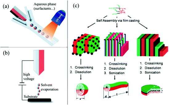 | ||
| Fig. 2 Overview of direct preparation methods of Janus particles. (a) Micro-fluidic system; (b) electrospinning using a bi-phasic nozzle; (c) self-assembly of triblock terpolymers. Reprinted from ref. 60. Copyright the Royal Society of Chemistry 2008. | ||
The indirect template-assisted method addresses the chemical or physical modifications of the hemispheric surfaces of existing mono-disperse particles. Particle embedding on substrate surfaces is required to conceal one hemispheric surface and to modify the other exposed hemisphere with chemical functionalities or geometric shapes. Particle adsorption and embedding are usually conducted on 2D flat surfaces (Fig. 3a).72–74 The major drawback of this strategy is that the amount of particles is extremely limited and does not allow their use in larger scale application studies. Nevertheless, due to its simplicity, this approach is still in use today.
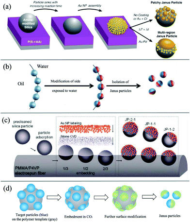 | ||
| Fig. 3 Overview of indirect template-assisted methods of Janus particles. (a) 2D flat soft substrate. Reprinted with permission from ref. 72. Copyright 2010 American Chemical Society. (b) Liquid/liquid interface template. Reprinted with permission from ref. 60. Copyright the Royal Society of Chemistry 2008. (c) Fiber polymer substrate. Reprinted with permission from ref. 87. Copyright 2010 American Chemical Society. (d) Spherical polymer substrate. Reprinted with permission from ref. 89. Copyright the Royal Society of Chemistry 2013. | ||
To overcome this limitation, spherical substrates offer an opportunity to increase the surface-to-volume ratio. For example, the effective fabrication of Janus silica particles has been demonstrated using suspended wax micro-particles as embedding vehicles by Granick and co-workers (Fig. 3b).75,76 The concept essentially transforms the two-dimensional technique into a solution phase and uses the high internal interface of an oil (wax)–water emulsion to achieve higher mass fractions of Janus particles. In a first step, they created a Pickering emulsion of wax and water using silica particles as stabilizers at high temperature. After cooling down of the emulsion and a purification step, the particles were immobilized at the solidified interface. The key step of this process is the immobilization of the particles at the interface and the suppressed rotational diffusion of the particles at the solidified interface. The Janus particles can then be obtained after functionalization of one side with aqueous phase chemistry and filtration at higher temperatures. This technique was subsequently used by other researchers to design various types of functional Janus NPs.77–82 For example, Okubo et al. have reported the formation of “mushroom-like” Janus particles from various polymer systems using this technique.83–86 Recently, Muller's group also synthesized hybrid silica Janus NPs with a poly(2-(dimethylamino)ethyl methacrylate) (PDMAEMA) hemicorona. Their Janus NPs show a reversible switching behavior upon pH and temperature changes and thus can self-assemble into linear strings at low pH and high concentration.
Another example of using polymer fiber as scaffolds for the immobilization of the particles to prepare Janus particles was presented by Kuo and coworkers (Fig. 3c).87,88 The authors reported the fabrication of binary and ternary Janus particles with even and uneven surface-functionalities by particle embedding and gas-phase silanization of the exposed surface.
In another approach (Fig. 3d), with the assistance of carbon dioxide (CO2), polymer particles can be softened to allow a part of the rigid particle to be embedded inside their surface. With the embedded side being protected by a polymer substrate, further surface modification can be made on the other exposed side of rigid particles to form Janus-type NPs with subsequent removal of polymer templates by dissolving or thermal degradation. In this method,89,90 a spherical polymer template with a large surface-to-volume ratio allows larger-scale production compared with 2D masking methods. Due to the benefits of their solid features after embedding, polymer substrates also demonstrate superior stability for particle spacing among templates compared to interface substrates suspended in liquid media. They can also simplify purification and separation with a liquid washing process, which is a great challenge for preparation methods based on immobilizing particles on a liquid/liquid or liquid/air interface. On the other hand, this method is quite suitable for preparing rigid inorganic or metal particles, but it may not be the best choice for other polymeric or “soft” Janus NPs, which can also be softened inside CO2.
In brief, these abundant methods offer additional options to achieve Janus NPs. For example, Yabu et al. attempted different techniques to achieve organic–inorganic composite Janus NPs with various functional properties.91–95 But we should keep in mind that each of these approaches has its own merits and limitations, and people should choose the most suitable one to obtain the type of Janus NP for their own practical needs.27
3. Interfacial properties of Janus nanoparticles at fluid–fluid interfaces
The necessity to control and direct the self-assembly of NPs into defined superstructures arises from the need in materials and bio/life sciences to better exploit their often high intrinsic functionalities (e.g., electronic, mechanic, magnetic, conducting, and optic) for advanced materials. The ability to programme and reconfigure such structures so that they organize and restructure on demand is one of the ultimate goals. In this regard, external field-assisted alignment techniques may offer economical alternatives for fabricating highly ordered composite nanostructures. For example, various groups have already incorporated magnetic NPs or magnetic/metallic caps to investigate the self-assembly behavior of Janus NPs in magnetic96–103 or electric fields.104,105A fluid–fluid interface is a natural platform for obtaining monolayer self-assembled structures of Janus NPs. Due to their high interfacial activity and amphiphilicity, Janus NPs can effectively lower the interfacial tension and thus strongly absorb and orient at the interface or surface, similarly to the mixed brush captured nanoparticles.106,107 One class of this interfacial location is the so-called Pickering effect of Janus NPs at the fluid–fluid or fluid–air interface, known as surfactant particles for emulsification.47–49 De Gennes, who called attention to Janus NPs in his Nobel Prize address,108 described the spontaneous monolayer arrangement from Janus NPs at, for instance, a water–air interface as a “breathable skin”. He predicted the possibility of matter exchange between the two phases, which has recently been realized using Janus NPs as interfacial catalyst emulsifiers.109–112
The main reason why Janus NPs are able to stabilize emulsions and show their superior long-term stability more effectively than homogeneous particles can be explained by their strong adsorption energy to the fluid interface. Binks and Fletcher theoretically studied the energy to detach a single Janus NP from an oil–water interface, assuming a flat interface, as shown in Fig. 4a.113 The total surface free energy (E) for a Janus NP at the interface as a function of the angle β in Fig. 4 is given by:
For β ≤ α
For β ≥ α
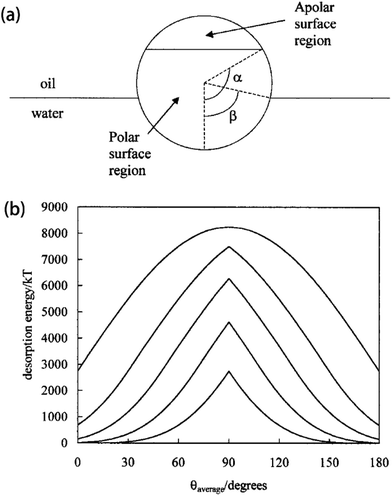 | ||
| Fig. 4 (a) Geometry of a Janus particle at an oil–water interface with parameters α and β, which represent positions of the Janus boundary and the interface, respectively. (b) Variation of particle desorption energy with area-weighted average contact angle for particles of radius 10 nm and α = 90°. Reprinted with permission from ref. 113. Copyright 2001 American Chemical Society. | ||
The amphiphilicity of Janus NPs can be “tuned” by the magnitude of the difference between the two contact angles θA and θP, Δθ = (θP − θA)/2. Zero amphiphilicity (corresponding to homogeneous particles) corresponds to Δθ = 0. The strongest amphiphilicity is expected when Δθ = 90°. According to their calculation of the desorption energy of a Janus NP for the fluid interface in Fig. 4b, it was shown that increasing the particle amphiphilicity through Δθ increases the strength of particle adsorption up to a maximum of three-fold for a θaverage of 90°. In addition, Janus NPs maintain their strong adsorption at average contact angles approaching 0 or 180° where the surface activity of the non-amphiphilic (homogeneous with Δθ = 0) particles is low.113 Further extensive theoretical simulations and experimental observations indicate that the interfacial activity of the Janus NPs can vary depending on several parameters, including the shape, size, morphology, and distribution of the spatial domains, and that the Janus NPs show an enhanced interfacial activity compared to the corresponding homogeneous particles, regardless of the synthesis and interfacial activity characterization methods.114–128
In analogy to the emulsification of fluid mixtures, Janus NPs are also expected to strongly attach to the interface inside polymer matrices, either in polymer blends or in block copolymers, which will be discussed in sections 3 and 4, respectively. A thorough study of the interfacial behavior of Janus NPs at the fluid–fluid interface is not only essential for further practical application of Janus NPs as solid stabilizers, but also helpful for fundamentally understanding how Janus NPs interact with polymeric interfaces, even though polymer interfaces cannot be simply understood as a fluid–fluid interface. The flexibility and chemical properties of long-chain polymers should be considered as well.
4. Janus nanoparticles as compatibilizers for polymer blends
Using molecular simulations, Estridge and Jayaraman129 compared the interfacial activity of different types of compatibilizers inside polymer blends, including diblock copolymer grafted nanoparticles (DBCGPs), BCPs, and Janus homopolymer grafted nanoparticles (JGPs). They showed that Janus NPs have the largest desorption energy due to their deeper penetration of the grafted beads into the A and B domain of the blend (Fig. 5a), and the lowest average interfacial tension of the compatibilized blend (γ) normalized to the blend without compatibilizers (γ0) at all volume fractions of the compatibilizing agent ϕ considered (Fig. 5c).129 Unlike DBCGPs and BCPs, Janus NPs localized directly at the interface, allowing all the A (B) homopolymers grafted on one (other) hemisphere of the particle to interact with the A (B) domain of the blend (Fig. 5b) at all volume fractions of Janus NPs considered.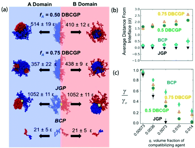 | ||
| Fig. 5 (a) Energetic penalty for leaving the interface. These are representative snapshots of compatibilizer configurations at the interface and within each domain, and the desorption energies associated with each case. (b) Average distance of the compatibilizer from the interface versus volume fraction ϕ (the same x-axis as (c)). (c) Reduction in interfacial tension. Ratio of compatibilized blend interfacial tension (γ) to compatibilizer-free blend interfacial tension (γ0) versus ϕ. Error bars are standard error. Reprinted with permission from ref. 129. Copyright 2015 American Chemical Society. | ||
While a number of experimental and theoretical reports have demonstrated its advantages in improving the miscibility of immiscible binary polymers, homogeneous NPs still face complications in their use to stabilize polymer blends. Depending on variances in the surface chemistry, preferential wetting of homogeneous NPs inside one component can often occur. Interfacial adsorption can only be achieved if the difference between the interfacial tension values for the particles with each component is less than the interfacial tension of pure polymer blends themselves.130,131 Janus NPs, however, are expected to exhibit a higher surface activity than homogeneous NPs and hence greatly reduce the interfacial tension to achieve interfacial location.
By taking the homogeneous NPs as a reference for comparison, numerical simulations by Guo and co-workers132,133 found that Janus nanospheres significantly hamper domain growth, and the average size of domains is smaller at later stages of the phase separation process (Fig. 6). Combining their other observations in ternary systems containing Janus NPs – including the slow domain growth at immediate and late times, crossover scaling domain growth behavior with the exponent close to 1, and closer saturation of phase separation – they indicated that Janus nanospheres are equatorially adsorbed at interfaces and are not desorbed from the interface into the bulk. They concluded that Janus nanospheres can be used as a more effective emulsifying or stabilizing agent than homogeneous nanospheres for immiscible polymer blends.
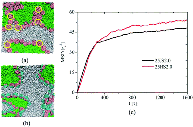 | ||
| Fig. 6 Two regions selected from snapshots of 25HS2.0 (a) and 25JS2.0 (b) systems at t1/4 = 1600 s, which encompass a typical configuration that is seen throughout the samples. The yellow circle, which is drawn to guide the eye, outlines the nanoparticles that are not equatorially adsorbed at interfaces. The green, gray, pink, and cyan colors correspond to homopolymers A, homopolymers B, and p and q hemispheres of Janus nanospheres, respectively. (c) The mean square displacement of nanospheres in the 25JS2.0 and 25HS2.0 systems. Reprinted with permission from ref. 132. Copyright the Royal Society of Chemistry 2012. | ||
More interestingly, by utilizing a Cahn-Hilliard model with Langevin equations, Krekhov et al. demonstrated that adding Janus particles above a certain concentration to a phase-separating binary mixture drives the system into regular structures with interfacially sequestered particles. Their simulation results propose a promising strategy to create periodic structures in binary mixtures by adding Janus particles.134
Experimentally, Virgilio and Favis investigated the effect of the affinity of Janus NPs and found that the Janus NPs consisting of polystyrene (PS) and poly(methyl methacrylate) (PMMA) spherical caps are interfacially active and locate at the high-density polyethylene (HDPE) and polypropylene (PP) interface.135 Walther et al.136 also confirmed that organic Janus particles can be used to efficiently compatibilize polymer blends under high-shear conditions. Their results showed a constant decline of the domain size of the dispersed phase with the increased addition of Janus NPs, independent of the PS and PMMA blend composition. In the transmission electron microscopy (TEM) images (Fig. 7), Janus NPs were observed to be almost exclusively located at the interface of the PS and PMMA domains, and only a negligibly small fraction was “lost” as unimers or micellar aggregates in one of the components. They considered this a significant improvement compared to BCP compatibilizers as a direct consequence of the high interfacial activity and increased adsorption energy at interfaces of Janus NPs.136 Janus-type kaolinite platelets obtained by Weiss et al. also showed an interfacial activity of Janus particles in PS/PMMA blends obtained by a solvent casting procedure.137
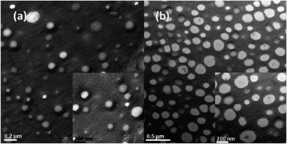 | ||
| Fig. 7 TEM images of Janus particles and their adsorption at the blend interface of a PS/PMMA blend obtained for (a) 10 wt% JP in an 8/2 PS/PMMA blend and (b) 20 wt% JP in a 6/4 PS/PMMA blend. Reproduced with permission from ref. 136. Copyright 2008 American Chemical Society. | ||
For industry-scale application, Bahrami et al. subsequently used 200 g of Janus NPs to compatibilize several kilograms of poly(2,6-dimethyl-1,4-phenylene ether) (PPE) and poly(styrene-co-acrylonitrile) (SAN) (Fig. 8).138 The scaled-up experiments indicated that the fraction of Janus NPs in the range of 2–5 wt% was the optimum amount necessary for sufficient droplet stabilization of PPE/SAN blends. The addition of only 0.5 and 1 wt% Janus NPs was not able to provide the necessary interface coverage and thus the blends were not mixed well. When a large amount of Janus NPs was added, excess content of Janus NPs inside the blends would create additional interfaces to form double emulsion morphologies.138 By using Janus NPs as the compatibilizer in the same polymer blend system, homogeneous polymeric foams with small cell sizes and relatively high densities are further produced with the plasticization of CO2.139
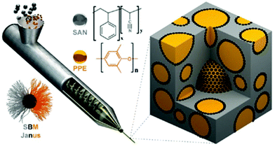 | ||
| Fig. 8 Schematic representation of processing of polymer blends using JPs as a compatibilizer during extrusion of the polymer melt. JPs (black dots) compatibilize and stabilize PPE droplets (yellow) within the SAN matrix (gray). Reprinted with permission from ref. 138. Copyright 2014 American Chemical Society. | ||
Remarkably, due to the combination of strong interfacial affinity and the Pickering effect, Janus NPs were still quantitatively absorbed at the blend interface in these industry-scale blending experiments despite the harsh shear-processing conditions (Fig. 8).136,138 Soon afterwards, they also achieved a controlled blend morphology by de-mixing in solvent-cast films by adjusting the content of Janus NPs in blends and the composition ratio between PS and PMMA.140 Interfacially trapped structures in the final Janus NPs showed good resistance to coarsening during several days of annealing well above the glass transition temperature of the components. Similar phenomena from Janus NPs were also observed in other different systems, such as immiscible poly(L-lactide) (PLLA)/poly(vinylidene fluoride) (PVDF) blends,141,142 polystyrene/polyamide-6 blends,143 and polybutadiene/polyisoprene rubber blends.144
Janus NPs in the examples above show their superiority over other methods for compatibilizing immiscible polymer blends. They can mitigate the micellization problems of a diblock copolymer stabilizer and the difficulty of achieving interfacial adsorption encountered by homogeneous particle surfactants. As long as Janus inorganic particles can be prepared at the industrial scale, it would be quite promising to achieve hybrid materials with desired functional properties simply by mixing them with properly chosen polymer blends.
5. Janus nanoparticles for ordered interfacial arrangement inside block copolymer scaffolds
To generate highly ordered NP-based functional materials, control of the spatial organization of the NPs inside polymers is essential. The ability to control the length, spatial, and orientational organization of BCP morphologies (from spherical to cylindrical, bicontinuous, and lamellar structures) makes BCP materials particularly attractive as templates for manipulating the spatial location of inorganic NPs in various scales, from micro to nano. Several reviews have summarized the progress made in understanding and controlling NP distribution in BCP-ordered structures.1–13Of particular interest is controlling the assembly of inorganic or metallic NPs, at the interface between different phase domains of the BCPs, to achieve a high degree of order and even responsive behaviors to certain external stimuli.145 However, interfacial location of NPs, and the overall morphology within BCPs, depends on a delicate balance between the enthalpy of NP insertion and the entropy related to particle conformation and translation, which are subjected to various interacting factors. These include the properties of BCPs (chemistry, conformation, and molecular weight) and of particles (selectivity, size, shape, and concentration).
5.1 Enthalpic effects
Enthalpic interactions rely on the surface chemistries of NPs and BCPs. With suitable grafting, polymeric ligands on NP surfaces can change the particle surface chemistry and effectively control NP–BCP enthalpic interactions and thus the location of NPs inside BCPs, either in one specific block domain or at the interface between blocks. For example, extensive studies were performed on the surface chemistry effect of NP grafting with polymeric ligands on their assemblies inside BCPs. It was shown that NPs, by modifying with A and B homopolymers, preferred to selectively localize within the A and B microdomains.However, according to Kramer and his co-workers’ observations, the surface coverage of polymer ligands on NPs can change this selectivity of NPs inside BCPs and, consequently, drive a shift in the spatial organization of NPs from inside the selective polymeric domain of the BCP matrix to the interfacial regions with the ligand areal density decrease. Polystyrene-thiol (PS-SH) ligand-coated gold nanoparticles (Au NPs) have a critical areal chain density ΣC below which NPs favorably adsorb to the interface. The ΣC decreased from 3.1 to 0.9 chains per nm2 as the Mn of PS-SH chains increased from 1.5 to 13 kg mol−1.146–148
For the purpose of interfacial localization of NPs inside BCPs with better stability, the preferred choices are particles with amphiphilic surface properties, such as a mixture of ligands or random copolymer-anchored NPs and Janus-type NPs. Kim et al. reported that gold particles, which are coated with a mixture of low molecular weight PS and poly(2-vinyl pyridine) (P2VP) thiols, were observed to segregate at the interfaces between the PS-P2VP blocks over a broad range of PS fractions (FPS) from 0.1 to 0.9 (Fig. 9).149,150
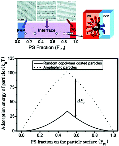 | ||
| Fig. 9 (Upper) The spatial organization of Au NPs coated with a mixture of low molecular weight thiol end-functional PS/P2VP can be controlled in PS-b-P2VP. Varying the PS and P2VP surface compositions (FPS) on the Au NPs allows placing the NPs into PS or P2VP microdomains or at the interface. (Lower) Adsorption energies for 4 nm radius random copolymer-coated NPs (solid line) and amphiphilic NPs (dotted line) are plotted as a function of FPS. Reprinted with permission from ref. 150. Copyright 2007 American Chemical Society. | ||
In stark contrast, Au NPs with surfaces covered by a random copolymer of styrene and 2-vinyl pyridine with FPS = 0.40 remained in the P2VP domain and far away from the interface. However, random copolymer-coated Au NPs became clearly segregated along the PS/P2VP when the fraction increased to 0.52, which is consistent with the results in Fig. 9.150
Afterwards, Kim and Matsen developed a quantitative theoretical method to examine the effect of grafted brushes on the equilibrium distribution of spherical NPs inside the BCP lamellar phase by implementing self-consistent field theory and a new multi-coordinate-system scheme.151 Their simulation conclusions agreed with the experimental result that the mixed brushes are significantly more effective than the random-copolymer brushes at positioning NPs at the interface. However, the preference for the interface was much stronger than expected from simple surface-tension consideration, especially when mixture-grafted particles had a majority of PS chains on the surface (Fps = 0.9).
To explain the results, Kim et al. hypothesized that chains of the mixed brush segregate to opposite hemispheres, creating Janus NPs, as long as an appropriate time scale is involved. Once the particles adsorb at the interface, the ligands can rearrange on the AuNP surface, leading to strengthened adhesion and a pinning to the interface. They self-confirmed this possibility by their simple calculations on the adsorption energy of random copolymer-coated NPs to the interface (Fig. 9).150 Similar phenomena were also observed in polymer blends that interface by small-angle neutron scattering. It was revealed that two polymer ligands of high molecular weight showed phase separation to form a Janus-type shell on the NP surface, whereas those of low molecular weight formed either a mixed or partly de-mixed shell.152
The question arises, then, whether it is still necessary to use Janus NPs to capture interfaces, especially when mixed ligands or random copolymer-grafted NPs can do the same job and are even easier to prepare. The answer is affirmative for several reasons. First, as discussed in various examples above,129,149–151 Janus NPs theoretically show higher interfacial absorption energy than random copolymer-grafted NPs (or mixed polymer ligand-coated NPs without phase separation to form the Janus type) and thus are more preferentially located at the interface. Second, even though ligand exchanges on Au NPs are likely to form Janus-type particles at the polymer interface, it is not always true for other types of metallic or inorganic NPs, which endow hybrid materials with optical, magnetic, or electronic properties that Au NP-based hybrid materials cannot achieve. Actually, gold NPs with mixed ligands still were observed dispersing within one of the microdomains in PS-b-P2VP when the ratio of dodecanethiol to 1,1-mercapto-1-undecanol ligand was changed from 1![[thin space (1/6-em)]](https://www.rsc.org/images/entities/char_2009.gif) :
:![[thin space (1/6-em)]](https://www.rsc.org/images/entities/char_2009.gif) 1 to 3
1 to 3![[thin space (1/6-em)]](https://www.rsc.org/images/entities/char_2009.gif) :
:![[thin space (1/6-em)]](https://www.rsc.org/images/entities/char_2009.gif) 1.153 Also, coated with a ligand mixture with a molar ratio of approximately 5
1.153 Also, coated with a ligand mixture with a molar ratio of approximately 5![[thin space (1/6-em)]](https://www.rsc.org/images/entities/char_2009.gif) :
:![[thin space (1/6-em)]](https://www.rsc.org/images/entities/char_2009.gif) 1 of 1-dodecanethiol
1 of 1-dodecanethiol![[thin space (1/6-em)]](https://www.rsc.org/images/entities/char_2009.gif) :
:![[thin space (1/6-em)]](https://www.rsc.org/images/entities/char_2009.gif) PS-SH, Au NPs showed an affinity for PS-rich domains but did not localize at the interface in poly-(styrene-b-isoprene-b-styrene) triblock copolymer thin films.154 In these cases, the entropic effects surpassed enthalpic ones playing the main role in the location of NPs inside BCPs. However, limited by the rare experimental studies on the incorporation of Janus NPs into BCP scaffolds, it is difficult to draw a firm conclusion on which type of particle is better for interfacial location. To compare and thus reach a conclusion, more thorough studies on Janus NPs are needed.
PS-SH, Au NPs showed an affinity for PS-rich domains but did not localize at the interface in poly-(styrene-b-isoprene-b-styrene) triblock copolymer thin films.154 In these cases, the entropic effects surpassed enthalpic ones playing the main role in the location of NPs inside BCPs. However, limited by the rare experimental studies on the incorporation of Janus NPs into BCP scaffolds, it is difficult to draw a firm conclusion on which type of particle is better for interfacial location. To compare and thus reach a conclusion, more thorough studies on Janus NPs are needed.
5.2 Entropic effects
From the point of view of the enthalpy effect – that is, interaction between NPs and BCPs – Janus NPs with two chemically different grafting compartments tend to absorb at the interface inside BCPs. These benefit from their higher interfacial activity than homopolymer-coated NPs, and from their stronger amphiphilicity compared to homogeneous polymer-grafted NPs. However, their ordering and interface-centered position inside BCP composites is not simply determined by their surface chemistry, but usually governed by an intricate balance of enthalpic and entropic interactions. Therefore, entropic effects relying on the size, shape, and chain properties of BCPs should also be considered in designing new materials with regard to the orientation and off-center position at the interface.It is remarkable to note that the conclusion on size-dependent interfacial location of Janus NPs in BCP scaffolds from Wang et al.155 seems opposite to that of homogeneous NPs inside BCPs addressed by both theory and modelling.148,156,157 For example, it was found that relatively smaller homogeneous particles (with the ratio of NP diameter, dNP, to the BCP domain size, L, being smaller than 0.2) were located in the interfacial regions of a polystyrene-b-poly(ethylene propylene) (PS-b-PEP) diblock copolymer, whereas relatively large NPs (dNP/L > 0.3) were localized in the interior of the PEP domains.2 There is, in fact, no conflict to observe completely different locations of larger Janus NPs and homogeneous NPs in the BCP matrix. Both systems indicate that favorable enthalpic interaction and minimal loss in the conformation entropy determine the particles’ positions.
As an example, for larger particles, Janus types locate at the interface due to their amphipathicity and homogeneous ones are sequestered in the interior of one selective polymeric block. For smaller homogeneous particles, the stretching required by the polymers to circumvent the spheres is less significant. Hence, it is the translational entropy of the particles that dominates the system's behavior.158 However, more reasonable theoretical explanations and experimental results are needed to explain the random distribution, but not interfacial arrangement, of smaller Janus NPs in BCP scaffolds.
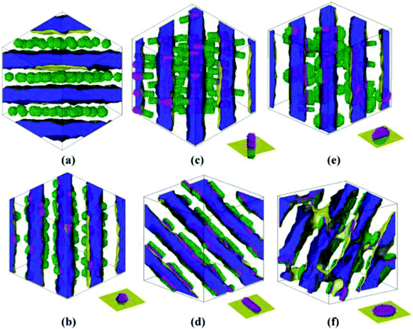 | ||
| Fig. 10 Equilibrium self-assemblies formed by various NPs in symmetric diblock copolymers. The volume fraction of each type of NP is 0.15. The interface between phases A and B is shown in yellow, and phase A is displayed as half-transparent blue. Phase B is fully transparent. The types of NPs are (a) homogeneous sphere with radius Rs = 2rc, (b) Janus sphere with Rs = 2rc, (c) one type of Janus rod with radius of the bottom face Rr = 1.5rc and height Lr = 9rc, (d) another type of Janus rod with the same size as (c), (e) one type of Janus disk with radius of the bottom face Rd = 3.5rc and thickness Ld = 2rc, and (f) the other type of Janus disk with the same size as that of (e). The schematic diagrams at the right bottom of images b–f illustrate the orientation of Janus NPs with respect to the interface. Reprinted with permission from ref. 159. Copyright 2010 American Chemical Society. | ||
It is interesting to note that the orientation of these anisotropic Janus NPs, with respect to the interface, can be controlled upon changing their surface and shape architectures, especially for Janus rods and disks. It was also suggested that Janus NP-containing diblock copolymers could allow better processing due to enhanced shear dynamics and feasible viscosity changes.159 Therefore, by using Janus-type NPs with surface and shape architectures, even more interfacial, stable, functional, and hybrid composites can be reached with oriented structures and responsive behaviors to certain external stimuli.
For systems presenting a lamellar phase with flat-phase interfaces, Janus NPs tend to move to A domains for the longer B segments, of which the stretched conformation makes it difficult for the Janus NPs to be positioned in the B segment.160 However, for even larger B segment systems, where the phase interface curves (BCP morphologies cylinder), the increase of B segments also causes Janus NPs to shift off-center from the interface but turn to the B domains.160 In this case, the topology mismatching between Janus NPs and curved polymer interfaces at the meso-scale accounts for the Janus NPs’ position transition.160 Similarly, the semiflexible block's stiffness can also regulate the off-center distribution of symmetrical Janus NPs with respect to the phase interface, featured by a roughly 35% deviation from the interface to the utmost extent (Fig. 11).161
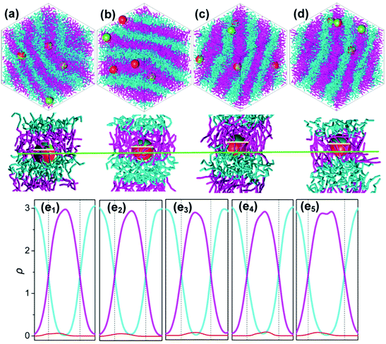 | ||
| Fig. 11 (a–d) Representations of the self-assembly of Janus NPs in AB diblock copolymers with a flexible A block but with B block of various stiffnesses: (a) Ka = 0 kBT, (b) Ka = 40 kBT, (c) Ka = 100 kBT, and (d) Ka = 300 kBT. At each Ka, the top snapshot shows the self-assembled morphologies where the cyan and pink chains denote blocks A and B, and sites P and Q of every Janus NP are shown in red and yellow, respectively. The bottom snapshot highlights the detailed position of a Janus NP at the interface and the conformation of the polymer chains around it. The green and yellow lines mark the phase interface and the equator of the NP (e1–e5). The density profiles of blocks A (cyan) and B (pink) and the Janus NP (red) are shown for various stiffnesses of block B: (e1) Ka = 5 kBT, (e2) Ka = 40 kBT, (e3) Ka = 60 kBT, (e4) Ka = 100 kBT, and (e5) Ka = 400 kBT. Reprinted with permission from ref. 161. Copyright 2015American Chemical Society. | ||
6. Summary and outlooks
Studies on the interfacial behavior of Janus NPs at the fluid–fluid interface are fundamental for understanding how Janus NPs interact with polymeric interfaces and thus designing hybrid materials. Based on the theoretical simulations and experimental studies, Janus NPs show their superiority over other methods for compatibilizing, regardless of the harsh processing conditions.For the purpose of interfacial localization of NPs inside BCPs with better stability, particles with amphiphilic surface properties are the preferred choices, including mixtures of ligands or random copolymer-anchored NPs and Janus-type NPs. Compared with random copolymer-grafted NPs and mixed polymer ligand-anchored NPs without phase separation, Janus NPs show higher interface activity and amphipathicity. They were observed still remaining in the block interface region even during shearing, independent of their shape, and therefore hybrid material with higher performance properties could be expected. Entropic effects rely on the size, shape, and chain properties of BCPs, but also play an important role in the orientation and off-center position at the interface, which is interesting for tailoring the band gaps of optical nanocomposites.
This type of hybrid materials based on the precise location of Janus NPs at the interface in polymeric materials can combine the functional properties of NPs with the mechanical properties of polymer matrices. With properly choosing the type of Janus NP and polymer, one therefore can flexibly design functional hybrid nanostructures and devices with engineered, desired, and tailored properties toward real-life applications.
Despite these theoretical studies, establishing more detailed knowledge regarding the effect of Janus NPs on their positions in BCP scaffolds is still needed to create nanocomposites with desired structures: especially an experimental study, which is still rare, perhaps due to the more complicated synthesis required. Motivating additional efforts in large-scale synthesis and interfacial behavior studies of Janus NPs for the design of these smart materials is actually one of the main purposes of this review.
Abbreviations
| NP | Nanoparticle |
| BCP | Block copolymer |
| CO2 | Carbon dioxide |
| AO | Apolar–oil |
| PO | Polar–oil |
| AW | Apolar–water |
| PW | Polar–water |
| OW | Oil–water |
| DBCGPs | Diblock copolymer grafted nanoparticles |
| PS | Polystyrene |
| PMMA | Poly(methyl methacrylate) |
| HDPE | High-density polyethylene |
| PP | Polypropylene |
| TEM | Transmission electron microscopy |
| PPE | Poly(2,6-dimethyl-1,4-phenylene ether) |
| SAN | Poly(styrene-co-acrylonitrile) |
| PS-SH | Polystyrene-thiol |
| Au NP | Gold nanoparticle |
| P2VP | Poly(2-vinyl pyridine) |
| SCFT/DFT | Self-consistent field theory/density functional theory |
| PS-b-PEP | Polystyrene-b-poly(ethylene propylene) |
| PEP | Poly(ethylene propylene) |
Acknowledgements
The authors acknowledge funding support from the China Scholarship Council and the Netherlands Organisation for Scientific Research (NWO).References
- A. C. Balazs, T. Emrick and T. P. Russell, Science, 2006, 314, 1107–1110 CrossRef CAS PubMed.
- B. Sarkar and P. Alexandridis, Prog. Polym. Sci., 2015, 40, 33–62 CrossRef CAS.
- J. Huh, V. V. Ginzburg and A. C. Balazs, Macromolecules, 2000, 33, 8085–8096 CrossRef CAS.
- R. A. Vaia and J. F. Maguire, Chem. Mater., 2007, 19, 2736–2751 CrossRef CAS.
- M. R. Bockstaller, R. A. Mickiewicz and E. L. Thomas, Adv. Mater., 2005, 17, 1331–1349 CrossRef CAS.
- R. Shenhar, T. B. Norsten and V. M. Rotello, Adv. Mater., 2005, 17, 657–669 CrossRef CAS.
- A. Haryono and W. H. Binder, Small, 2006, 2, 600–611 CrossRef CAS PubMed.
- A. Fahmi, T. Pietsch, C. Mendoza and N. Cheval, Mater. Today, 2009, 12, 44–50 CrossRef CAS.
- M. Grzelczak, J. Vermant, E. M. Furst and L. M. Liz-Marzán, ACS Nano, 2010, 4, 3591–3605 CrossRef CAS PubMed.
- K. Galatsis, K. L. Wang, M. Ozkan, C. S. Ozkan, Y. Huang, J. P. Chang, H. G. Monbouquette, Y. Chen, P. Nealey and Y. Botros, Adv. Mater., 2010, 22, 769–778 CrossRef CAS PubMed.
- H.-C. Kim, S.-M. Park and W. D. Hinsberg, Chem. Rev., 2010, 110, 146–177 CrossRef CAS PubMed.
- H. Zhang, Y. Liu, D. Yao and B. Yang, Chem. Soc. Rev., 2012, 41, 6066–6088 RSC.
- J. Kao, K. Thorkelsson, P. Bai, B. J. Rancatore and T. Xu, Chem. Soc. Rev., 2013, 42, 2654–2678 RSC.
- M. Segev-Bar and H. Haick, ACS Nano, 2013, 7, 8366–8378 CrossRef CAS PubMed.
- B. Yoon, W. D. Luedtke, R. N. Barnett, J. P. Gao, A. Desireddy, B. E. Conn, T. Bigioni and U. Landman, Nat. Mater., 2014, 13, 807–811 CrossRef CAS PubMed.
- L. Z. Yi, W. H. Jiao, K. Wu, L. H. Qian, X. X. Yu, Q. Xia, K. M. Mao, S. L. Yuan, S. Wang and Y. T. Jiang, Nano Res., 2015, 8, 2978–2987 CrossRef CAS.
- N. Kahn, O. Lavie, M. Paz, Y. Segev and H. Haick, Nano Lett., 2015, 15, 7023–7028 CrossRef PubMed.
- W. Zhao, J. Luo, S. Y. Shan, J. P. Lombardi, Y. Xu, K. Cartwright, S. Lu, M. Poliks and C. J. Zhong, Small, 2015, 11, 4509–4516 CrossRef CAS PubMed.
- I. Tokarev and S. Minko, Soft Matter, 2012, 8, 5980–5987 RSC.
- Y.-G. He, S.-Y. Shi, N. Liu, Y.-Y. Zhu, Y.-S. Ding, J. Yin and Z.-Q. Wu, RSC Adv., 2015, 5, 39697–39704 RSC.
- S. Fateixa, H. I. S. Nogueira and T. Trindade, Phys. Chem. Chem. Phys., 2015, 17, 21046–21071 RSC.
- A. X. Wang and X. M. Kong, Materials, 2015, 8, 3024–3052 CrossRef PubMed.
- W.-P. Lin, S.-J. Liu, T. Gong, Q. Zhao and W. Huang, Adv. Mater., 2014, 26, 570–606 CrossRef CAS PubMed.
- J. Y. Ouyang, J. Mater. Chem. C, 2015, 3, 7243–7261 RSC.
- G. M. Kang, J. Yoo, J. Ahn and K. Kim, Nano Today, 2015, 10, 22–47 CrossRef CAS.
- G. Li, R. Zhu and Y. Yang, Nat. Photonics, 2012, 6, 153–161 CrossRef CAS.
- A. Walther and A. H. E. Müller, Chem. Rev., 2013, 113, 5194–5261 CrossRef CAS PubMed.
- A. Synytska, R. Khanum, L. Ionov, C. Cherif and C. Bellmann, ACS Appl. Mater. Interfaces, 2011, 3, 1216–1220 CAS.
- H. Xing, Z. D. Wang, Z. D. Xu, N. Y. Wong, Y. Xiang, G. L. Liu and Y. Lu, ACS Nano, 2012, 6, 802–809 CrossRef CAS PubMed.
- S.-H. Kim, S. Y. Lee and S.-M. Yang, Angew. Chem., Int. Ed., 2010, 49, 2535–2538 CrossRef CAS PubMed.
- J. L. Tang, K. Schoenwald, D. Potter, D. White and T. Sulchek, Langmuir, 2012, 28, 10033–10039 CrossRef CAS PubMed.
- M. Yoshida, K. H. Roh, S. Mandal, S. Bhaskar, D. W. Lim, H. Nandivada, X. P. Deng and J. Lahann, Adv. Mater., 2009, 21, 4920–4925 CrossRef CAS PubMed.
- C. Kaewsaneha, P. Tangboriboonrat, D. Polpanich, M. Eissa and A. Elaissari, ACS Appl. Mater. Interfaces, 2013, 5, 1857–1869 CAS.
- L.-T.-C. Tran, S. Lesieur and V. Faivre, Expert Opin. Drug Delivery, 2014, 11, 1064–1074 Search PubMed.
- I. Schick, S. Lorenz, D. Gehrig, S. Tenzer, W. Storc, K. Fischer, D. Strand, F. Laquai and W. Tremel, Beilstein J. Nanotechnol., 2014, 5, 2346–2362 CrossRef PubMed.
- Y. J. Wu, X. K. Lin, Z. G. Wu, H. Möhwald and Q. He, ACS Appl. Mater. Interfaces, 2014, 6, 10476–10481 CAS.
- H. H. Wang, S. Y. Yang, S.-N. Yin, L. Chen and S. Chen, ACS Appl. Mater. Interfaces, 2015, 7, 8827–8833 CAS.
- S. Nedev, S. Carretero-Palacios, P. Kühler, T. Lohmüller, A. S. Urban, L. J. E. Anderson and J. Feldmann, ACS Photonics, 2015, 2, 491–496 CrossRef CAS PubMed.
- K. Miki, H. Hashimoto, T. Inoue, H. Matsuoka, H. Harada, M. Hiraoka and K. Ohe, Small, 2014, 10, 3119–3130 CrossRef CAS PubMed.
- J. H. Yoon, J. H. Lim and S. Yoon, ACS Nano, 2012, 6, 7199–7208 CrossRef CAS PubMed.
- Y. Duk Han, H.-S. Kim, Y. M. Park, H. J. Chun, J.-H. Kim and H. C. Yoon, ACS Appl. Mater. Interfaces, 2016, 8, 10767–10774 Search PubMed.
- A. J. Logsdail and R. L. Johnston, J. Phys. Chem. C, 2012, 116, 23616–23628 CAS.
- M. Guix, C. C. Mayorga-Martinez and I. A. Merkoç, Chem. Rev., 2014, 114, 6285–6322 CrossRef CAS PubMed.
- X. Ma, A. Jannasch, U.-R. Albrecht, K. Hahn, A. Miguel-López, E. Schäffer and S. Sánchez, Nano Lett., 2015, 15, 7043–7050 CrossRef PubMed.
- W. Gao, A. Pei, R. F. Dong and J. Wang, J. Am. Chem. Soc., 2014, 136, 2276–2279 CrossRef CAS PubMed.
- W. Gao and J. Wang, ACS Nano, 2014, 8, 3170–3180 CrossRef CAS PubMed.
- A. Kumar, B. J. Park, F. Tu and D. Lee, Soft Matter, 2013, 9, 6604–6617 RSC.
- L. Botto, E. P. Lewandowski, J. M. Cavallaro and K. J. Stebe, Soft Matter, 2012, 8, 9957–9971 RSC.
- A. Böker, J. He, T. Emrick and T. P. Russell, Soft Matter, 2007, 3, 1231–1248 RSC.
- Y. Komazaki, H. Hirama and T. Torii, J. Appl. Phys., 2015, 117, 154506 Search PubMed.
- A. M. Boymelgreen and T. A. Miloh, Phys. Fluids, 2011, 23, 072007 CrossRef.
- Y. Daghighi and D. Q. Li, Lab Chip, 2011, 11, 2929–2940 RSC.
- A. M. Boymelgreen and T. Miloh, Phys. Fluids, 2012, 24, 082003 CrossRef.
- L. Zhang and Y. X. Zhu, Appl. Phys. Lett., 2010, 96, 141902 CrossRef.
- X. Pang, C. Wan, M. Wang and Z. Lin, Angew. Chem., Int. Ed., 2014, 53, 5524–5538 CrossRef CAS PubMed.
- J. Reguera, H. Kim and F. Stellacci, Chimia, 2013, 67, 811–818 CrossRef CAS PubMed.
- J. Hu, S. Zhou, Y. Sun, X. Fang and L. Wu, Chem. Soc. Rev., 2012, 41, 4356–4378 RSC.
- B. T. T. Pham, C. H. Such and B. S. Hawkett, Polym. Chem., 2015, 6, 426–435 RSC.
- M. Lattuadaa and T. A. Hattonb, Nano Today, 2011, 6, 286–308 CrossRef.
- A. Walther and A. H. E. Müller, Soft Matter, 2008, 4, 663–668 RSC.
- A. Perro, S. Reculusa, S. Ravaine, E. Bourgeat-Lami and E. Duguet, J. Mater. Chem., 2005, 15, 3745–3760 RSC.
- G. Loget and A. Kuhn, J. Mater. Chem., 2012, 22, 15457–15474 RSC.
- K.-H. Roh, D. C. Martin and J. Lahann, Nat. Mater., 2005, 4, 759–763 CrossRef CAS PubMed.
- Z. Liu, D. D. Sun, P. Guo and J. O. Leckie, Nano Lett., 2007, 7, 1081–1085 CrossRef CAS PubMed.
- R. Erhardt, M. Zhang, A. Böker, H. Zettl, C. Abetz, P. Frederik, G. Krausch, V. Abetz and A. H. E. Müller, J. Am. Chem. Soc., 2003, 125, 3260–3267 CrossRef CAS PubMed.
- R. Erhardt, A. Böker, H. Zettl, H. Kaya, W. Pyckhout-Hintzen, G. Krausch, V. Abetz and A. H. E. Müller, Macromolecules, 2001, 34, 1069–1075 CrossRef CAS.
- Y. Liu, V. Abetz and A. H. E. Müller, Macromolecules, 2003, 36, 7894–7898 CrossRef CAS.
- A. Walther, X. André, M. Drechsler, V. Abetz and A. H. E. Müller, J. Am. Chem. Soc., 2007, 129, 6187–6198 CrossRef CAS PubMed.
- A. H. Gröschel, A. Walther, T. I. Löbling, J. Schmelz, A. Hanisch, H. Schmalz and A. H. E. Müller, J. Am. Chem. Soc., 2012, 134, 13850–13860 CrossRef PubMed.
- P. Hiekkataipale, T. I. Löbling, M. Poutanen, A. Priimagi, V. Abetz, O. Ikkala and A. H. Gröschel, Polymer, 2016, 107, 457e466 CrossRef.
- K. Kawamoto, M. J. Zhong, K. R. Gadelrab, L.-C. Cheng, C. A. Ross, A. Alexander-Katz and J. A. Johnson, J. Am. Chem. Soc., 2016, 138, 11501–11504 CrossRef CAS PubMed.
- M. D. McConnell, M. J. Kraeutler, S. Yang and R. J. Composto, Nano Lett., 2010, 10, 603–609 CrossRef CAS PubMed.
- A. G. Skirtach, D. G. Kurth and H. Möhwald, Appl. Phys. Lett., 2009, 94, 093106 CrossRef.
- X. Y. Ling, I. Y. Phang, C. Acikgoz, M. D. Yilmaz, M. A. Hempenius, G. J. Vancso and J. Huskens, Angew. Chem., Int. Ed., 2009, 48, 7677–7682 CrossRef CAS PubMed.
- S. Jiang and S. Granick, Langmuir, 2008, 24, 2438–2445 CrossRef CAS PubMed.
- L. Hong, S. Jiang and S. Granick, Langmuir, 2006, 22, 9495–9499 CrossRef CAS PubMed.
- T. M. Ruhland, H. S. McKenzie, T. S. Skelhon, S. A. F. Bon, A. Walther and A. H. E. Muller, Polymer, 2015, 79, 299–308 CrossRef CAS.
- E. Sharifzadeh, M. Salami-Kalajahi, M. S. Hosseini and M. K. R. Aghjeh, Colloids Surf., A, 2016, 506, 56–62 CrossRef CAS.
- A. Zenerino, C. Peyratout and A. Aimable, J. Colloid Interface Sci., 2015, 450, 174–181 CrossRef CAS PubMed.
- W. L. Li, X. J. Cai, S. H. Ma, X. H. Zhan, F. Lan, Y. Wu and Z. W. Gu, RSC Adv., 2016, 6, 40450–40458 RSC.
- Y. H. Wang, C. L. Zhang, C. Tang, J. Li, K. Shen, J. G. Liu, X. Z. Qu, J. Li, Q. Wang and Z. Z. Yang, Macromolecules, 2011, 44, 3787–3794 CrossRef CAS.
- R. H. Deng, H. Li, J. T. Zhu, B. H. Li, F. X. Liang, F. Jia, X. Z. Qu and Z. Z. Yang, Macromolecules, 2016, 49, 1362–1368 CrossRef CAS.
- T. Tanaka, M. Okayama, Y. Kitayama, Y. Kagawa and M. Okubo, Langmuir, 2010, 26, 7843–7847 CrossRef CAS PubMed.
- H. Ahmad, N. Saito, Y. Kagawa and M. Okubo, Langmuir, 2008, 24, 688–691 CrossRef CAS PubMed.
- N. Yamashita, N. Konishi, T. Tanaka and M. Okubo, Langmuir, 2012, 28, 12886–12892 CrossRef CAS PubMed.
- T. Yamagami, Y. Kitayama and M. Okubo, Langmuir, 2014, 30, 7823–7832 CrossRef CAS PubMed.
- C. C. Lin, C. W. Liao, Y. C. Chao and C. S. Kuo, ACS Appl. Mater. Interfaces, 2010, 2, 3185–3191 CAS.
- C. C. Ho, W. S. Chen, T. Y. Shie, J. N. Lin and C. S. Kuo, Langmuir, 2008, 24, 5663–5666 CrossRef CAS PubMed.
- Q. Yang, M. H. de Vries, F. Picchioni and K. Loos, Nanoscale, 2013, 5, 10420–10427 RSC.
- Q. Yang, Q. Xu and K. Loos, Macromolecules, 2015, 48, 1786–1794 CrossRef CAS.
- H. Yabu, K. Koike, K. Motoyoshi, T. Higuchi and M. Shimomura, Macromol. Rapid Commun., 2010, 31, 1267–1271 CrossRef CAS PubMed.
- H. Yabu, K. Motoyoshi, T. Higuchi and M. Shimomura, Phys. Chem. Chem. Phys., 2010, 12, 11944–11947 RSC.
- T. Arita, M. Kanahara, K. Motoyoshi, K. Koike, T. Higuchi and H. Yabu, J. Mater. Chem. C, 2013, 1, 207–212 RSC.
- H. Yabu, M. Kanahara, M. Shimomura, T. Arita, K. Harano, E. Nakamura, T. Higuchi and H. Jinnai, ACS Appl. Mater. Interfaces, 2013, 5, 3262–3266 CAS.
- H. Yabu, H. Ohshima and Y. Saito, ACS Appl. Mater. Interfaces, 2014, 6, 18122–18128 CAS.
- J. Yan, M. Bloom, S. C. Bae, E. Luijten and S. Granick, Nature, 2012, 491, 578–581 CrossRef CAS PubMed.
- J. Yan, K. Chaudhary, S. C. Bae, J. A. Lewis and S. Granick, Nat. Commun., 2013, 4, 1516 CrossRef PubMed.
- J. Yan, S. C. Bae and S. Granick, Adv. Mater., 2015, 27, 874–879 CrossRef CAS PubMed.
- J. Yan, S. C. Bae and S. Granick, Soft Matter, 2015, 11, 147–153 RSC.
- A. Ruditskiy, B. Ren and I. Kretzschmar, Soft Matter, 2013, 9, 9174–9181 RSC.
- B. Ren and I. Kretzschmar, Langmuir, 2013, 29, 14779–14786 CrossRef CAS PubMed.
- B. Ren, A. Ruditskiy, J. H. Song and I. Kretzschmar, Langmuir, 2012, 28, 1149–1156 CrossRef CAS PubMed.
- S. Sacanna, L. Rossi and D. J. Pine, J. Am. Chem. Soc., 2012, 134, 6112–6115 CrossRef CAS PubMed.
- B. Bharti and O. D. Velev, Langmuir, 2015, 31, 7897–7908 CrossRef CAS PubMed.
- P. C. Song, Y. F. Wang, Y. Wang, A. D. Hollingsworth, M. Weck, D. J. Pine and M. D. Ward, J. Am. Chem. Soc., 2015, 137, 3069–3075 CrossRef CAS PubMed.
- J. L. Cheng, J. P. He, C. X. Li and Y. L. Yang, Chem. Mater., 2008, 20, 4224–4230 CrossRef CAS.
- Y. Z. Wang, D. Q. Fan, J. P. He and Y. L. Yang, Colloid Polym. Sci., 2011, 289, 1885–1894 CAS.
- P. G. De Gennes, Rev. Mod. Phys., 1992, 64, 645–648 CrossRef.
- J. Faria, M. P. Ruiz and D. E. Resasco, Adv. Synth. Catal., 2010, 352, 2359–2364 CrossRef CAS.
- D. J. Cole-Hamilton, Science, 2010, 327, 41–42 CrossRef CAS PubMed.
- W. Cao, R. Huang, W. Qi, R. Su and Z. He, ACS Appl. Mater. Interfaces, 2015, 7, 465–473 CAS.
- C. Wu, S. Ba, M. B. Ansorge-Schumacher and D. Wang, Adv. Mater., 2011, 23, 5694–5699 CrossRef CAS PubMed.
- B. P. Binks and P. D. I. Fletcher, Langmuir, 2001, 17, 4708–4710 CrossRef CAS.
- M. A. Fernandez-Rodriguez, J. Ramos, L. Isa, M. A. Rodriguez-Valverde, M. A. Cabrerizo-Vilchez and R. Hidalgo-Alvarez, Langmuir, 2015, 31, 8818–8823 CrossRef CAS PubMed.
- A. Walther, M. Hoffmann and A. H. E. Müller, Angew. Chem., Int. Ed., 2008, 47, 711–714 CrossRef CAS PubMed.
- M. A. Fernandez-Rodriguez, M. A. Rodriguez-Valverde, M. A. Cabrerizo-Vilchez and R. Hidalgo-Alvarez, Adv. Colloid Interface Sci., 2016, 233, 240–254 CrossRef CAS PubMed.
- H. Rezvantalab and S. Shojaei-Zadeh, ACS Nano, 2016, 10, 5354–5361 CrossRef CAS PubMed.
- Q. G. Xie, G. B. Davies and J. Harting, Soft Matter, 2016, 12, 6566–6574 RSC.
- E. Passas-Lagos and F. Schüth, Langmuir, 2015, 31, 7749–7757 CrossRef CAS PubMed.
- J. Lenis, S. Razavi, K. D. Cao, B. H. Lin, K. Y. C. Lee, R. S. Tu and I. Kretzschmar, J. Am. Chem. Soc., 2015, 137, 15370–15373 CrossRef CAS PubMed.
- D. L. Wu, J. W. Chew and A. Honciuc, Langmuir, 2016, 32, 6376–6386 CrossRef CAS PubMed.
- H. Rezvantalab, G. Drazer and S. Shojaei-Zadeh, J. Chem. Phys., 2015, 142, 014701 CrossRef PubMed.
- H.-M. Gao, Z.-Y. Lu, H. Liu, Z.-Y. Sun and L.-J. An, J. Chem. Phys., 2014, 141, 134907 CrossRef PubMed.
- X. C. Luu, J. Yu and A. Striolo, J. Phys. Chem. B, 2013, 117, 13922–13939 CrossRef CAS PubMed.
- X. C. Luu and A. Striolo, J. Phys. Chem. B, 2014, 118, 13737–13743 CrossRef CAS PubMed.
- D. L. Cheung and S. A. F. Bon, Soft Matter, 2009, 5, 3969–3976 RSC.
- T. Tanaka, M. Okayama, H. Minami and M. Okubo, Langmuir, 2010, 26, 11732–11736 CrossRef CAS PubMed.
- Q. G. Xie, G. B. Davies, F. Günther and J. Harting, Soft Matter, 2015, 11, 3581–3588 RSC.
- C. E. Estridge and A. Jayaraman, ACS Macro Lett., 2015, 4, 155–159 CrossRef CAS.
- T. Nakano, D. Kawaguchi and Y. Matsushita, J. Am. Chem. Soc., 2013, 135, 6798–6801 CrossRef CAS PubMed.
- C. W. Huang, J. P. Gao, W. Yu and C. X. Zhou, Macromolecules, 2012, 45, 8420–8429 CrossRef CAS.
- M. X. Huang, Z. Q. Li and H. X. Guo, Soft Matter, 2012, 8, 6834–6845 RSC.
- M. X. Huang and H. X. Guo, Soft Matter, 2013, 9, 7356–7368 RSC.
- A. Krekhov, V. Weith and W. Zimmermann, Phys. Rev. E: Stat. Phys., Plasmas, Fluids, Relat. Interdiscip. Top., 2013, 88, 040302 CrossRef PubMed.
- N. Virgilio and B. D. Favis, Macromolecules, 2011, 44, 5850–5856 CrossRef CAS.
- A. Walther, K. Matussek and A. H. E. Muller, ACS Nano, 2008, 2, 1167–1178 CrossRef CAS PubMed.
- S. Weiss, D. Hirsemann, B. Biersack, M. Ziadeh, A. H. E. Müller and J. Breu, Polymer, 2013, 54, 1388–1396 CrossRef CAS.
- R. Bahrami, T. I. Löbling, A. H. Gröschel, H. Schmalz, A. H. E. Müller and V. Altstädt, ACS Nano, 2014, 8, 10048–10056 CrossRef CAS PubMed.
- S. Barwinkel, R. Bahrami, T. I. Lobling, H. Schmalz, A. H. E. Muller and V. Altstadt, Adv. Eng. Mater., 2016, 18, 814–825 CrossRef.
- K. C. Bryson, T. I. Löbling, A. H. E. Müller, T. P. Russell and R. C. Hayward, Macromolecules, 2015, 48, 4220–4227 CrossRef CAS.
- H. T. Wang, Z. Fu, W. Y. Dong, Y. J. Li and J. Y. Li, J. Phys. Chem. B, 2016, 120, 9240–9252 CrossRef CAS PubMed.
- H. T. Wang, W. Y. Dong and Y. J. Li, ACS Macro Lett., 2015, 4, 1398–1403 CrossRef CAS.
- T. Parpaite, B. Otazaghine, A. S. Caro, A. Taguet, R. Sonnier and J. M. Lopez-Cuesta, Polymer, 2016, 90, 34–44 CrossRef CAS.
- H. R. Nie, C. Zhang, Y. W. Liu and A. H. He, Macromolecules, 2016, 49, 2238–2244 CrossRef CAS.
- Z. Y. Liu, R. H. Guo, G. X. Xu, Z. H. Huang and L.-T. Yan, Nano Lett., 2014, 14, 6910–6916 CrossRef CAS PubMed.
- B. J. Kim, J. Bang, C. J. Hawker and E. J. Kramer, Macromolecules, 2006, 39, 4108–4114 CrossRef CAS.
- B. J. Kim, G. H. Fredrickson, J. Bang, C. J. Hawker and E. J. Kramer, Macromolecules, 2009, 42, 6193–6201 CrossRef CAS.
- B. J. Kim, G. H. Fredrickson and E. J. Kramer, Macromolecules, 2008, 41, 436–447 CrossRef CAS.
- J. J. Chiu, B. J. Kim, E. J. Kramer and D. J. Pine, J. Am. Chem. Soc., 2005, 127, 5036–5037 CrossRef CAS PubMed.
- B. J. Kim, J. Bang, C. J. Hawker, J. J. Chiu, D. J. Pine, S. G. Jang, S.-M. Yang and E. J. Kramer, Langmuir, 2007, 23, 12693–12703 CrossRef CAS PubMed.
- J. U. Kim and M. W. Matsen, Phys. Rev. Lett., 2009, 102, 078303 CrossRef PubMed.
- S. Kim, T.-H. Kim, J. Huh, J. Bang and S.-H. Choi, ACS Macro Lett., 2015, 4, 417–421 CrossRef CAS.
- Q. F. Li, J. B. He, E. Glogowski, X. F. Li, J. Wang, T. Emrick and T. P. Russell, Adv. Mater., 2008, 20, 1462–1466 CrossRef CAS.
- M. K. Mayeda, W.-F. Kuan, W.-S. Young, J. A. Lauterbach and T. H. Epps III, Chem. Mater., 2012, 24, 2627–2634 CrossRef CAS.
- L. Q. Wang, J. P. Lin and X. M. Zhu, RSC Adv., 2012, 2, 12870–12878 RSC.
- M. R. Bockstaller, Y. Lapetnikov, S. Margel and E. L. Thomas, J. Am. Chem. Soc., 2003, 125, 5276–5277 CrossRef CAS PubMed.
- C. T. Lo, Y. C. Chang, S. C. Wu and C. L. Lee, Colloids Surf., A, 2010, 368, 6–12 CrossRef CAS.
- R. B. Thompson, V. V. Ginzburg, M. W. Matsen and A. C. Balazs, Science, 2001, 292, 2469–2472 CrossRef CAS PubMed.
- L.-T. Yan, N. Popp, S.-K. Ghosh and A. Böker, ACS Nano, 2010, 4, 913–920 CrossRef CAS PubMed.
- B. J. Dong, R. H. Guo and L.-T. Yan, Macromolecules, 2014, 47, 4369–4379 CrossRef CAS.
- B. J. Dong, Z. H. Huang, H. L. Chen and L.-T. Yan, Macromolecules, 2015, 48, 5385–5393 CrossRef CAS.
| This journal is © The Royal Society of Chemistry 2017 |


