Architectural evolution of phase domains in shape memory polyurethanes by dissipative particle dynamics simulations
Jinlian
Hu
*ab,
Cuili
Zhang
ab,
Xun
Li
c,
Jianping
Han
ab and
Fenglong
Ji
d
aInstitute of Textiles and Clothing, the Hong Kong Polytechnic University, Hung Hom, Kowloon, Hong Kong, China
bThe Hong Kong Polytechnic University Shenzhen Base, Shenzhen, China. E-mail: tchujl@polyu.edu.hk
cDepartment of Applied Mathematics, the Hong Kong Polytechnic University, Hung Hom, Kowloon, Hong Kong, China
dSchool of Textiles and Clothing, Wuyi University, Jiangmen, Guangdong 529020, China
First published on 24th August 2016
Abstract
Shape memory effects in shape memory polyurethane (SMPU) are due to a network architecture formed by phase separation. Here we study the phase domain architectures of a series of SMPUs by dissipative particle dynamics simulations with different hard segment contents (HSC, 4,4′-diphenylmethane diisocyanate (MDI) and 1,4-butanediol (BDO)). By simulation, an evolutionary 3D netpoint-switch-frame unit-cell model is established. With the increase of HSCs, from our simulated massive data, the MDI phase develops a framework with netpoints evolving from spheres, to linked-spheres, to linked-cylinders, and then to linked-bi-crossing-cylinders at the nanoscale, while the PCL as the switch evolves from a filling-matrix, to linked-layers, to tri-crossing-cylinders, and then to linked-bi-crossing cylinders. The BDO does not show regular shape, but acts as an inter-phase between PCL and MDI, which supports the formation of a more perfect framework. This work verifies existing data, integrates reported schematic models and extends openings for the structural and performance design of smart materials.
1. Introduction
Shape memory polyurethane (SMPU) is a kind of very important smart material,1–3 which can remember and recover its permanent shape when exposed to certain external stimuli such as heat,4–9 microwave heating,10 light,11 electricity12 or electrically resistive Joule heating,10 magnetic field,13 water14 or moisture,15 pH,15 solvents16etc., and some good reviews for ways to trigger the shape memory effect were reported,10,15,17 while the shape memory effect originates from the architectural evolution of state domains.18,19 The SMPUs are usually block copolymers composed of hard segments (HSs) and soft segments (SSs).20 Due to the incompatibility between different blocks of SMPUs, the segregation of the HSs from the SSs, namely, phase separation, leads to the formation of hard micro-domains.21,22Structural perfection and the degree of phase separation have been found to be important to both the shape memory and mechanical properties of SMPUs,23–25 and related to the hard segment content (HSC). A SMPU with PEG SSs was found to have good shape memory effects due to the formation of a semicrystalline phase serving as a switch when the HSC is lower than 40 wt%.20 By AFM imaging, isolated hard-segment domains were reported for a SMPU with 25 wt% HSC while connected hard-segment domains were obtained for the SMPU with 40 wt% HSC in Cao's study.26 In addition, interconnection between continuous hard micro-domains was observed when the HSC was above 45 wt% in Liem's work.27 In our previous research, the hard domain of a supramolecular SMPU was understood to change from a droplet-like dispersion phase to a continuous morphology when the N,N-bis(2-hydroxyl ethyl) isonicotinamide (BINA, soft segment) content drops from 40 to 30 wt%.28 In general, increasing the HSC, i.e. the average hard segment molecular weight, leads to an increase in the degree of micro-phase separation, the hard domain size and order as well as the crystallinity, while a phase inversion occurs between 40 wt% and 45 wt% HSC29 or with low soft segment content (for example <50 wt%).30 From the reported work, it can be seen that the morphologies of different SMPUs vary with different HSCs, where the hard phase domain may have an isolated, interconnected or connected continuous-domain structure. These results are actually very coarse and scattered due to the different types of individual block SMPUs studied by different researchers. Thus none of them can represent a systematic and rational structural evolution of the SMPUs with different HSCs. In response to this situation,31,32 the morphological evolution of SMPUs with different HSCs from 10 to 50 wt% was characterized by combined experimental techniques (Fig. 1a–c and g), which suggested that no hard-segment domains existed for SMPUs with 10 wt% or less HSC (Fig. 1d), an isolated hard-segment phase was obtained for SMPUs with HSC above 15 wt% (Fig. 1e), and a transition from isolated states to interconnected continuous states was proposed for those SMPUs with 40 to 45 wt% HSC (see Fig. 1e and f). As this morphological evolution is still crude, more details of such structures from 2D and 3D perspectives are required to explain their shape memory properties and engineer suitable SMPUs for different applications.
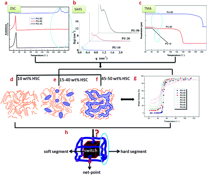 | ||
| Fig. 1 Experimental data and schematic models of SMPUs.31–33 (a) DSC results. (b) SAXA results. (c) TMA results. (d) Morphological model: no hard-segment domain for 10 wt% HSC. (e) Morphological model: isolated hard-segment domain for 15–40 wt% HSC. (f) Morphological model: interconnected hard-segment domain for 45–50 wt% HSC. (g) Shape recovery as a function of stimulating temperature for SMPUs with different HSCs. (h) A generalised shape memory structural model for shape memory polymers. | ||
From the above review, very simple facts of phase separation and domain connections are reported for SMPUs, but no specific shapes and dimensions of different domains are uncovered for this type of block copolymer. Since SMPUs are relatives of normal polyurethanes (PUs), it is sensible for us to refer to the knowledge of normal PUs. It has been reported that, at low hard segment contents, spherical34–36 and cylindrical37 hard segment domains were assumed to disperse in the soft segment matrix, while an alternating hard- and soft-segment rodlike or lamellar microdomain structure was characteristic for higher hard-segment contents.37–39 A transition from discrete to continuous hard-microdomain morphology was found as the HSC was increased above 50 wt% for MDI/BDO/polyoxypropylene-2000 (2000 MW polyoxypropylene),40 while for MDI/BDO/PTMO-1000 (l000 MW poly(tetramethylene oxide) (PTMO)) polyurethanes, the change was found as the MDI content increased from 24 to 28 wt%.41 Typically the size scale is on the order of 10 nm,42 and one of 30 nm was obtained for the hard segment domain in a 51 wt% hard segment PU,43 while the interlamellar distance was also reported to be in the range of a few hundred Angstroms.36
From a theoretical point of view, premature phase separation during the reaction of polyurethane block copolymers was explored using a Monte Carlo (MC) method developed specially for this process,44 and it was found that higher NSA (self-affinity effects begin) values correspond to phase separation occurring later in the reaction and resulted in a reduced influence of self-affinity on the various distributions. In Tao et al.'s work, the phase diagram and degree of phase separation of PUs were calculated by applying a combination of molecular dynamics (MD) simulation and a MC method, and they indicated that polyurethane with longer hard segments exhibited a higher degree of phase separation.45 In addition, the influence of diisocyanate symmetry and the nature of the hydrogen bonding between different hard segments on the morphology development of two-segmented polyurethanes and polyureas without a chain extender was investigated by both quantum mechanical calculations and dissipative particle dynamics DPD simulations. It was reported that long-range connectivity of hydrogen bonds between urethane and urea groups in 1,4-phenylene diisocyanate (PPDI) based segmented copolymers can form microphase separated morphologies, but kinked 1,3-phenylene diisocyanate (MPDI) based copolymers do not display well-defined microphase separation.46
In the literature, polyurethanes (PUs) and their functional counterparts: shape memory polyurethanes (SMPUs), are normally treated as two-phase (or di-block) structural copolymers, namely, hard and soft segments, but they do have three kinds of monomers including polyol, diisocyanate and a chain extender, and it may be more reasonable if they are regarded as tri-block copolymers for more detailed analyses of their structures. It has been well understood that tri-block copolymers can produce a wide range of morphologies according to the chemical nature of their components. In addition to the discovery of ordered spherical,47,48 cylindrical,48 lamellar,49–52 and ordered tri-continuous double-diamond structures (OTDD),49,50 which bear the same basic structural features as the corresponding structures in AB di-block copolymers, several intriguing new morphologies have been reported. The morphologies, which are a combination of the lamellar, cylinder, and spherical phases in tri-block copolymers, were first predicted by Riess et al.53 These new structures include lamella-cylinder,54–57 lamella-sphere,54–56 cylinder-ring,54,55 cylinder-sphere,56 and hexagonally ordered coaxial cylinder phases.58 With the appearance of a “knitting pattern”, the intermediate of a morphology of A, B and C lamellae and a morphology of A and C lamellae with B cylinders at the A C−1 interface was reported by Breiner.59 Based on a tri-block polymer strategy, we used DPD simulations to study the architecture of a typical SMPU with 30 wt% HSC. A network unit-cell model with phase morphology was proposed,60 where the SMPU consists of both switch units and connected-spherical netpoints, corresponding to the soft segment and hard segment,61 respectively, while the chain extender plays the role of an interphase between the switch and netpoints.60
From the above systematic review of the phase separation of both PUs and SMPUs, we found that the phase separation is enhanced with an increase of the HSC. Although there are rich qualitative descriptions in the existing literature for the phase separation, the geometry of hard domains and their connections in the morphology of such tri-block copolymers, particularly different polyurethanes, the details of orderly phase architectures, a holistic architectural configuration and the evolutionary domain patterns from 2D and 3D perspectives of SMPUs are still not well understood particularly when using different chemical constitutions such as different HSCs. Moreover, theoretical studies on the relationship between the phase architecture and the HSC of SMPUs are rather scarce. In addition, through extensive theoretical simulations, we wonder whether the morphologies of different polyurethanes can be integrated in an explicit unit-cell to represent the structural evolution of SMPUs, which fits the shape memory polymer structural model. For these purposes, based on our pilot success in DPD simulation of a typical SMPU with 30 wt% HSC,31 the phase separation of a series of SMPUs with different HSCs32 is investigated extensively by a tri-block copolymer strategy, then architectural evolution in a unit-cell of shape memory polymers featured with phase morphologies will be proposed.
2. Theoretical method
For the data reported above, we adapted a dissipative particle dynamics (DPD) method developed by Hoogerbrugge and Koelman,62,63 which is a mesoscopic simulation technique for complex fluids that can study systems over larger length and time scales than classical Monte Carlo and molecular dynamics simulations. This method has been successfully applied to polymeric systems by introducing bead-spring type models64–66 and it is particularly suitable for investigating the microphase separation of block copolymers67 and polymer blends.66,68–702.1 System studied
In the present study, we designed an enlarged SMPU system with the composition based on our previous work32 to ensure that the number of monomers in all the blocks and DPD beads was equal to the nearest integer, as shown in Fig. 2. The hard segment content was increased by increasing the average hard segment length at a fixed soft segment length as in a previous study.71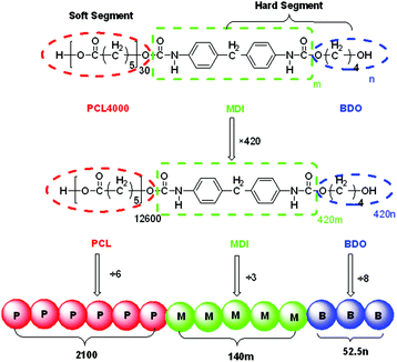 | ||
| Fig. 2 Design of DPD beads for SMPU (m and n correspond to the average number of MDI and BDO per hard segment in Table 1 of ref. 32, respectively). | ||
Due to the complexity in the molecular composition of shape memory polyurethane, possessing a long soft segment block and a very short hard segment block with very small extender molecules, the design of shape memory polyurethanes fit for DPD simulations is an extremely difficult process. Based on several attempts, to get reasonable results, the SMPU is treated as a tri-block copolymer in DPD simulations, where the soft segment PCL is regarded as one type of bead, while the hard segment MDI and the chain extender BDO are using two different types of beads. Firstly, the polymers studied were designed as 420 times the composition ratio for the three components, and then the numbers of blocks were divided by the number of monomers per DPD bead N (see Table 1) to calculate the quantity of DPD beads for each component, which is listed in Table 2.
| Monomer | Monomer volume Vm (Å3) | Monomer number per DPD bead N | Bead volume Vbead (Å3) |
|---|---|---|---|
| PCL | 103.6 | 6 | 621.6 |
| MDI | 199.3 | 3 | 598.0 |
| BDO | 74.22 | 8 | 593.8 |
| Polymers | HSC (wt%) (MDI + BDO) | N DPD/V% | ||
|---|---|---|---|---|
| PCL | MDI | BDO | ||
| PU10 | 10 | 2100/91.9 | 168/7.3 | 18/0.8 |
| PU15 | 15 | 2100/86.9 | 264/10.9 | 54/2.2 |
| PU20 | 20 | 2100/82.4 | 360/14.1 | 90/3.5 |
| PU25 | 25 | 2100/77.8 | 468/17.3 | 132/4.9 |
| PU30 | 30 | 2100/72.9 | 600/20.8 | 180/6.3 |
| PU35 | 35 | 2100/67.7 | 760/24.5 | 240/7.8 |
| PU40 | 40 | 2100/63.3 | 920/27.7 | 300/9.0 |
| PU45 | 45 | 2100/58.4 | 1120/31.2 | 375/10.4 |
| PU50 | 50 | 2100/53.3 | 1368/34.8 | 468/11.9 |
2.2 DPD method
For detailed theory of the DPD method, please refer to the literature.72,73The most important parameter to be determined is the maximum repulsive force aij, which is chosen according to the linear relation with Flory–Huggins χ parameters:73
| aij ≈ aii + 3.50χij for ρ = 3 | (1) |
2.3 χ parameter
The χ parameter between DPD pairs of particles was obtained from the solubility parameters using: | (2) |
Here, Vbead is the volume of polymer segment corresponding to the particle size in the DPD, R is the molar gas constant (J (mol K)−1), and T is the temperature in Kelvin, at which simulation is performed. δ is the solubility parameter.
2.4 Volume of DPD beads
From the introduction above of DPD theory, some parameters are needed to perform the DPD simulations. First, the volume of simulation beads should be determined to construct a mesoscopic model. Different beads representing a number of monomers are assumed to have equal volume, which is necessary to conform to the Flory–Huggins theory and the standard DPD model.74,75 The same density of beads for all species is restricted to make a stronger link with the experiments.76 The volumes of the monomers are obtained by quantitative structure property relationship (QSPR) methods,77 which are available in the synthia module in the Materials Studio software.78 Six PCL monomers are taken as one DPD bead, so the reference volume of one bead is about 600 Å3, approximately equal to the volume of 3 MDI monomers, or 8 BDO monomers, as shown in Table 1.2.5 Number of DPD beads in each polymer chain
Based on the composition of SMPU in ref. 32 with different hard segment content, the number of different DPD beads for each polymer chain is calculated using the method in the previous section ‘System studied’ with the same number of PCLs, which are listed in Table 2. The series of samples is designated as PUXX where XX stands for the hard-segment content (HSC).2.6 Interaction parameters
The solubility parameters (δ) for three components (PCL, MDI and BDO) of the SMPUs, generated using QSPR methods with Synthia,78 are given in Table 3.| Species | δ (J cm3)1/2 |
|---|---|
| PCL | 17.65 |
| MDI | 27.15 |
| BD | 19.34 |
Integrating eqn (1) and (2), the Flory–Huggins χ parameters and maximum repulsive force aij can be calculated, as shown in Table 4. The pair interaction parameters provide an integral measure of the interaction strength.
| Species | χ | a ij |
|---|---|---|
| PCL–MDI | 21.61 | 95.66 |
| PCL–BDO | 0.5969 | 26.95 |
| MDI–BDO | 14.67 | 72.97 |
2.7 DPD simulations
DPD simulations of the SMPU were performed in a cell of size 30 × 30 × 30, with a bead density ρ = 3, containing about 8.1 × 10⁴ DPD beads, and periodic boundary conditions were applied. Although a larger simulation box would be better to avoid finite size effects, it was too time-consuming, and it was found that, the size of the simulation box does not affect the radius of the phase domains.79 Thus this box was adopted. The finite size effects should not have been significant, since there was at least one domain in the present system for the polymers of length N = 30 studied in this work. For convenience, the particle mass m, and kBT were all taken as unity. The time step Δt was taken as 0.05,80 and adjacent particles in the polymer chain interacted via a linear spring with a harmonic spring constant of 4.0, according to Groot and Liu.81–83 Additionally, the friction coefficient γ was chosen as 4.5.83 A total of 8 × 10⁴ DPD steps were carried out for the DPD simulation in this work. All the DPD simulations were performed using the Materials Studio software package.783. Results and discussion
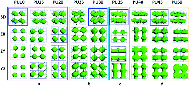
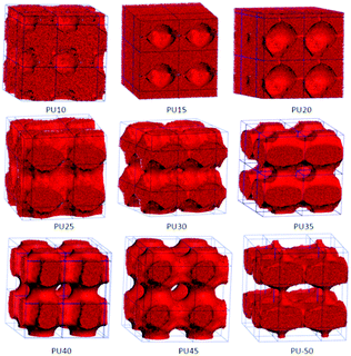
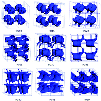
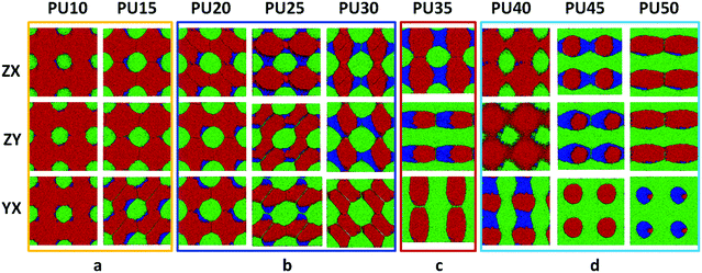
For DPD simulations, several polymer-segments are systematically treated as a single simulation bead based on the molar volume of the monomers. Different beads are assumed to have equal volume, and the interaction parameters between beads are estimated from Flory–Huggins χ parameters obtained from the solubility parameters. The architectures of each component MDI, PCL, and BDO, and every combination of two components are shown in Fig. 3–8. The phase morphologies of SMPU are listed in Fig. 9. The domain size for the MDI phase is listed in Table 5. The evolution of 2D phase morphologies for SMPU is presented in Fig. 10, and the SMP model combining the phase architectural evolution is shown in Fig. 11. From Fig. 3–9, we can find that the phases for the hard segment calculated for our system are comparable to those of the simulation box, and to better show the connections and distributions of each phase domain, we take the phase morphologies from the 2 × 2 × 2 cell with proper selection of the cell coordinates. The series of SMPUs is designated as PUXX where XX stands for the hard-segment content (HSC, wt%). The phase domain shown in Fig. 3–8 & 11 used both iso-density surface and mesoscale molecular display methods, while for Fig. 9 & 10, only the mesoscale molecular display method was used.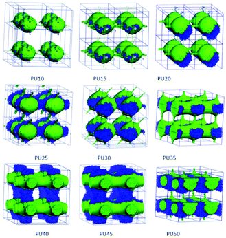 | ||
| Fig. 6 Architectural evolution of hard segment domains in SMPUs with different HSCs (green represents MDI and blue represents BDO). | ||
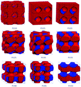 | ||
| Fig. 7 Architectural evolution of combined PCL and BDO phase domains in SMPUs with different HSCs (red represents PCL and blue represents BDO). | ||
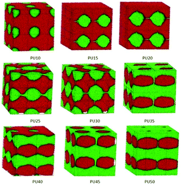 | ||
| Fig. 8 Architectural evolution of combined PCL and MDI phases in SMPUs with different HSCs (red represents PCL and green represents MDI). | ||
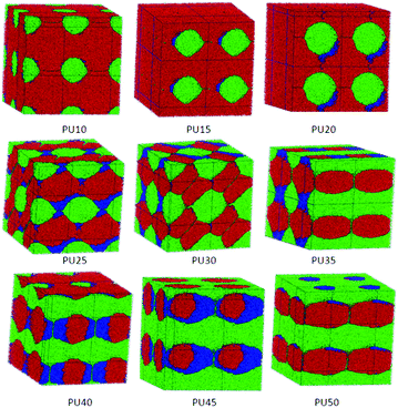 | ||
| Fig. 9 3D morphological evolution of SMPUs with different HSCs (red represents PCL, green represents MDI and blue represents BDO). | ||
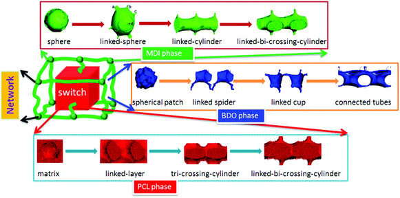 | ||
| Fig. 11 Shape memory polymer structural model with architectural evolution of different phase domains. | ||
| Polymers | Domain | Stick | Inside cylinder | ||||||||
|---|---|---|---|---|---|---|---|---|---|---|---|
| X | Y | Z | X | Y | Z | XY45° | YZ45° | X | Y | Z | |
| PU10 | 10.4 | 10.7 | 12.1 | ||||||||
| PU15 | 12.4 | 13.7 | 12.0 | ||||||||
| PU20 | 13.6 | 14.1 | 13.5 | 1.2 | |||||||
| PU25 | 15.3 | 13.7 | 12.5 | 1.2 | 1.3 | 1.3 | |||||
| PU30 | 14.5 | 16.5 | 15.3 | 1.1 | 1.3 | 1.0 | 1.1 | ||||
| PU35 | 14.7 | 11.5 | 1.5 | 1.4 | |||||||
| PU40 | 13.1 | 1.0 | 7.0 | ||||||||
| PU45 | 12.4 | 1.9 | 7.6 | ||||||||
| PU50 | 12.0 | 1.0 | 8.0 | ||||||||
3.1 Architectural evolution of MDI
As the main component of the hard segment, MDI plays a dominant role in determining the permanent shape of MDI-based shape memory polyurethanes. In this part, the structural evolution of the MDI phase will be analyzed.Firstly, the MDI phase exists as spheres with thin molecular connections in one direction for PU10, and some new molecular links appear in four directions for PU15. In addition to previous connections, a stronger connection in one direction is found for PU20. When the HSC reaches 25 wt%, enhanced connections in four directions are found. For PU30, much stronger connections in four directions with molecular connection in one more biased direction are observed. The diameters of the spherical phases are increased from 10.4 nm to 16.5 nm with an increase of the HSC from 10 wt% to 30 wt%, which is in good agreement with previous studies.42,43 For the spherical phases, with an increase of hard segments, the connections between the spherical phases become greater in number and stronger, and actual connections are formed from PU20 and solid connections appear from PU25, which are in good accordance with previous experimental studies.41 When the HSC reaches 35 wt%, cylinders linked with sticks in two vertical directions form, named linked-cylinders, which is in good agreement with our previous work.32 From PU40, crossing cylinders are connected with sticks and cylinders (see Fig. 3), which are named linked-bi-crossing-cylinders. At the same time, with an increase of the HSC, the diameters of the crossing cylinders (shown as inside cylinder in Table 5) become larger, from 7.0 to 8.0 nm, while those of the connected sticks firstly sharply rise to 1.9 nm from 1.0 nm, and then fall back to 1.0 nm again, due to the growth balance between the two types of linkers (cylinders and sticks).
From the above analyses, we found that there are mainly four types of MDI domain, which are spheres, linked-spheres connected in different directions, linked-cylinders in two directions and linked-bi-crossing-cylinders for the SMPUs with an increase of the HSC from 10 to 50 wt%. The shape of linked-spheres (PU25 and PU30) was also reported by Mologin for the structure of water-containing nafion,84 which is very similar to our previously proposed net-point model for shape memory polymers,33,60 indicating that it is reasonable to use the phase architecture presenting the shape memory model. Generally speaking, similar architectures to all of these four types of MDI phase architecture, presented and highlighted in the blue frames in the top row of Fig. 3, were also reported in the literature.32,41–43,84 In addition, comparing the shape memory model of shape memory polymers (see Fig. 1h) and the MDI phase architecture, it is clear that the architecture of the MDI phase can represent a network with netpoints of the shape memory polyurethane model, which becomes stronger and stronger (see Fig. 3) with an increase of the hard segment content.
3.2 Architectural evolution of the soft segment (PCL)
The soft segment is an essential component in shape memory polyurethanes, which plays the role of a switch in the shape memory behavior, but very scarcely has work paid attention to its phase evolution. In this section, the analysis of its structural evolution will be shown in Fig. 4.For a low hard segment content, PU10–PU20 (≤20 wt% HSC), the soft segment (PCL) presents a filling matrix for the hard segment to fill in and its phase turns to linked-layers for PU25 and PU30. For PU35–PU45, tri-crossing-cylinders emerge, and this kind of shape was reported by Mologin for the structure of water-containing nafion84 as a bicontinuous structure. Finally, the linked-bi-crossing-cylinder phase linked by sticks and cylinders appears for PU50.
3.3 Architectural evolution of BDO
As the chain extender of the hard segment, the phase morphologies of BDO are always regarded as part of the hard-segment phase in the literature and its phase details are never pointed out and totally absent in previous studies. In the present study, we treat the shape memory polyurethane as a tri-block copolymer, and the phase structures can be clearly presented for BDO. To better show the details of BDO phase structures, we extract the BDO phase from the whole PU, as shown in Fig. 5.The phase architectures of BDO change from isolated patches for PU10–PU20 and PU35, to a one-dimensionally-linked phase for PU30 with 30 wt% HSC, then to a two-dimensionally-linked phase for PU25, PU45 and PU50 with 25 wt%, 45 wt% and 50 wt% HSC, respectively, and finally to a three-dimensionally-linked phase for PU40 with 40 wt% HSC. The shapes of the phase architectures are not regular and not easy to describe, such as hollow spherical patches for PU10, shells for PU15, a comb with one handle for PU20, a linked-cup for PU25 and PU40, a linked-spider for PU30, and connected tubes for PU45 and PU50. From the above analyses, we can find that the evolution of the BDO phase architecture is not uniform and the changes for the shapes are not easy to classify.
3.4 Architectural evolution of the hard segment
It was suggested that hard segments get more aggregated to form domains in the SMPU block copolymer as the hard segment content increases.29 To show the combination of the two components in the hard segments (MDI and BDO), the combined phase architectures of MDI and BDO are both separated from the total morphologies of shape memory polyurethanes, as shown in Fig. 6. The MDI and BDO phases are to some extent incompatible, and they attach together contributing to the framework structures. For low HSCs (e.g. PU10), the BDO is just like small dots distributed on the spheres of the MDI phase. With an increase of the HSC, the BDO domain firstly self-assembles to enlarge the hard-segment domain (PU15–PU20), and then strengthens the connections among the hard-segment domains (PU25–PU45), and even helps the stick connections of the MDI phase to form comparable cylindrical connections for PU35–PU45. Finally, a connected layer or a connected lamellar domain of the hard-segment phase forms with combination of the MDI and BDO domain for PU50. These are in good accordance with the literature.37–39In our previous paper,32 using DSC we suggested that polyurethanes having over 25 wt% HSC possessed separated hard segment domains whereas PU-20 had no visible hard-segment domains. However, from the TMA and SAXS tests, PU-15 and PU-20 were shown to still contain more or less hard-segment phase that might be out of the sensitivity range of the DSC technique. The hard-segment phase changed from an isolated state to an interconnected state, or from a discontinuous phase to a continuous phase in such a HSC range for PU45 with 45 wt% HSC. The interconnected hard-segment phase formed a rigid framework which prevented the polymer from softening when the soft segment phase melted. The size of the hard-segment domains generally increased with the increasing HSC. In that work,32 the domain represented the crystal domain, so for PU10, no crystal domain was found, which indicates that no phase separation occurs. In the present simulation, true connected domains were found starting from PU20 with thin sticks, and these linkers may not crystallize and cannot be captured by experimental methods. Strong connections are found from PU40 in our simulations, which refer to the interconnected state in our previous work,32 and the SMPUs form connected phases a little earlier than that in the experimental results, maybe due to the noncrystalline nature of the connections in PU40.
From the above analysis, we can find that the architectural evolution of hard segments is dominated by the MDI phase, which contributes to the basic framework of the architectures of hard segments, and the architectures of BDO phases are dependent on the architectures of the MDI phase. The BDO phase is attached to the MDI domain in the unfilled regions just like a cushion around the MDI phase and supports the formation of a stronger hard-segment framework for shape memory polyurethanes. Our simulations agree well with our previous work.32 The obvious difference in phase architectures between our simulations and previous studies32,34–39,42,85–88 is the linkages between the domains, which may be specific characteristics of shape memory polyurethanes, and also show the advantage of the DPD simulations in the study of the phase separation of shape memory polyurethanes.
3.5 Architectural evolution of the combined PCL and BDO phases
To show the accumulating mode of the soft segment (PCL) and the chain extender (BDO), the combined phases of PCL and BDO are separated from the total phase morphologies of shape memory polyurethanes, as shown in Fig. 7.The PCL and BDO are incompatible with some mixing. At low HSCs (e.g. PU10), the BDO is just like small dots distributed on the vacant part of the PCL matrix. With an increase of the HSC, the BDO phase forms a connected web penetrating the PCL phase (PU45 and PU50), which helps the PCL phase form a crossing lamellar domain for PU40 and PU45 connected with cylinders, and tri-crossing-cylinders connected with cylinders for PU50. Comparing the phase structures of Fig. 6 and 7, we can find that the BDO phase prefers to develop in the unfilled regions between the PCL phase and the MDI phase, and supports the full shape memory polyurethane in forming a stable and symmetric framework.
3.6 Architectural evolution of the combined PCL and MDI phase domains
To show the accumulating mode of the soft segment (PCL) and MDI, the combined phases of PCL and MDI are separated from the total phase morphologies of shape memory polyurethanes, as shown in Fig. 8. The PCL and MDI are incompatible and separate as two phases. At low HSCs (<30 wt% HSC), the MDI phases are inlaid in the PCL matrix with some unfilled space between them. With an increase of the HSC, the MDI phase forms a connected framework crossing the PCL phase (PU35–PU50) with a larger space between the two phases, which refers to the BDO phases, indicating the role of the interphase for BDO and its cushioning function.3.7 Phase morphology of SMPUs
The nanoscale morphologies in Fig. 9 show that the hard segment is immiscible with the soft segment (PCL). For lower hard segment contents (HSC < 30 wt%), the hard-segment phases are dispersed in the matrix of the soft segment (PCL), which is in good agreement with the literature.34 From PU35 with 35 wt% HSC, the connections of hard-segment domains become thicker and thicker.When the HSC reaches 45 wt%, the volume distribution of the hard-segment domains develops comparably to the PCL domains, and the hard-segment phase begins to act as the filling matrix for the PCL phase to fill in, as the ratio of the PCL phase becomes less and less with the increase of the hard segment content. From Fig. 3 and 4, we can find that, from PU35, the MDI and PCL appear as alternating cylindrical domains, which is in good accordance with the literature.37–39
3.8 2D morphological evolution of SMPUs
Due to the limitations of experimental characterization techniques, some phenomena may not be detected, but with the simulations, more information and details can be obtained with the assistance of advanced methods and developed computational techniques. Fig. 10 clearly presents 2D morphological evolution in three directions with an increase of the HSC, which can vividly enrich our previous morphological model (see Fig. 1d–f).31,32 Firstly, the MDI phase of the hard segment shows an isolated spherical phase for PU10–PU15 (Fig. 10a), then spherical domains with connections in different directions for PU20–PU30 (Fig. 10b) filling in the soft segment matrix. After that, alternating linked cylinders for both segments appear with different connections (Fig. 10c and d), in good accordance with the literature.37–39 With the increase of the HSC, the distribution of hard-segment domains becomes wider and wider while the connections between hard-segment domains become stronger and stronger.3.9 Generalized SMPU model with architectural evolution
Comparing the spherical phase architecture of MDI in shape memory polyurethanes with our netpoint-switch-frame model for shape memory polymers (SMPs) proposed in our previous work,33 we can find that they are very similar, especially for PU30, which is just like a phase version of the SMP structural model. Thus we further propose that the SMPU model with different hard segment contents can be represented by phase architectural evolution in a unit-cell as seen in Fig. 11. Each chemical component of the block copolymer shows different functions in the shape memory effect. The MDI phase is regarded as the network in this model while the PCL phase is treated as the switch, and the BDO fills in the gap between the PCL phase and the MDI phase of the SMPUs just as a cushion, wedge or an interphase. With different HSCs, the three components may show different phase architectures. From 10 wt% to 50 wt%, the MDI phase develops from an isolated-spherical to a linked-spherical structure, to linked-cylindrical and then to a linked-bi-crossing-cylindrical configuration while the BDO phase transfers from spherical patches to 1D linked spiders, to a 2D linked cup and then to 3D connected tubes. At the same time, the PCL phase transforms from a filling matrix to a linked-layer, to a tri-crossing-cylindrical architecture, and then to a linked-bi-crossing-cylindrical architecture. In our previous paper, we found that SMPUs with low hard segment contents (≤35 wt%) showed better shape memory fixity. When HSC ≥40 wt%, the shape memory effect decreased rapidly.32 For low hard segment contents, the PCL phase is like a filling matrix with different connections between the MDI spherical domains, which leads to a higher shape fixity of the SMPUs, while for high hard segment contents, the PCL and MDI show alternative linked-crossing-cylindrical phases resulting in the lower shape fixity, as seen in Fig. 1 & 11. The decrease of shape fixity should result from the hard-segment phase changing from spheres to linked-bi-crossing-cylinders. From Fig. 6, we find that the hard-segment domains of PU40 form a rigid framework, and the hard-segment phase should be forced to deform during extension. This resulted in lower shape fixity of the SMPUs since the hard segment has an elastic property. Our shape memory structural model shown in Fig. 11, includes the full evolution of phase architectures for the three components in SMPUs, and integrates all the morphological models in the literature,42,85–88 and verifies the rationality of previous studies26,34–39,41–44. In particular, it shows the specific characteristics of shape memory polymers.4. Conclusions
The structures of polymers with different chemical compositions have a significant effect on their shape memory and mechanical properties, but there is not sufficient knowledge so far for the accurate description of such structures for a particular shape memory polymer, which limits the further development of smart materials for specific applications. In this paper, the architectural evolution of a series of SMPU morphologies was investigated using DPD simulations. An array of architectural phase separation domain images of SMPUs are then obtained based on tri-block copolymers, namely, MDI, PCL and BDO with different HSCs. Then the componential and architectural evolution of phase domains in the SMPUs with HSCs from 10 to 50 wt% can be vividly presented in terms of 2D and 3D morphologies with orderly phase architectural details. Through comprehensive analyses of the obtained images, this study confirms for the first time a holistic architectural configuration of a 3D netpoint-switch-frame unit-cell structure in SMPUs evolving with hard segment contents at the nanoscale by domain patterns from different perspectives. Even though we adapted a tri-block particle strategy in DPD, since the BDO phase takes up a comparatively very small volume, the simulated results can capture some basic features of a di-block copolymer consisting of PCL and MDI while the BDO domain acts as a cushion or wedge between PCL and MDI to maintain a more perfect unit-cell framework. Specifically, with the HSC ranging from 10 to 50 wt%, the MDI phase develops a 3D framework with netpoints evolving from spheres to linked-spheres, linked-cylinders, and linked-bi-crossing-cylinders with a linear dimension of 10.4–16.5 nm. The PCL forms a filling matrix as a switch at low HSCs and turns to linked-layers, to tri-crossing-cylinders, and then to linked-bi-crossing-cylinders with an increase of the HSC. The BDO phase transforms from isolated patches, to 1D linked spiders, then to 2D linked-hoses and finally to 3D connected-tubes. In general, although there is no regular geometry, the BDO phase tends to surround, complement and support the MDI for the formation of a stronger and more perfect framework, which is actually an inter-phase or cushion between the PCL and MDI phases. Our simulation results are in good accordance with our previous experiments32 and other researchers’ work,31,38–40,60 and can directly verify the conclusions from the experimental data with multiple techniques. The difference is that the simulated results have much more detail and more accurate classifications. For example, in our simulations, there are four general types of architectures for the SMPUs from 10 to 50 wt% HSC, but experimental results can only give roughly three types. From experimental data, we could only have a schematic of 2D qualitative random connection mapping of different phases, while simulation can give a detailed regular unit-cell for each type of domain structure. Thus the current work can make up for the limitations of experiments for a better understanding of the architecture of morphologies for shape memory polymers and integrate existing schematic models for shape memory polymers. From the DPD simulation, it is the first time that we have noted the universal existence of connections of phase elements for SMPUs in a unit-cell while the existing literature only gives very qualitative geometrical descriptions of block copolymer phase elements such as sphere, cylinder, lamellae, etc., and domains with connections only for high HSCs. This evolutionary netpoint-switch-frame structural model with different HSCs can open up new avenues for the structural and performance design of smart materials using simulation approaches. In addition, this work shows the fact that DPD simulation if adapted properly can be effectively applied for the structural design of polymers with many functional purposes such as structural colors through simulating optical crystals and drug release by predicting molecular self-assemblies, which is what we are aiming at for the next stage of our efforts.Acknowledgements
The authors wish to express their gratitude for the support of the Hong Kong Research Grants Council projects (RGC-GRF/5161/11E, RGC-GRF/5162/12E, RGC-GRF/d00914), National Natural Science Foundation of China (51373147), Shenzhen Biological, New Energy, New Material Industry Development Special Funds of China (JC201104210132A) and Funding Support for Project of Strategic Importance of The Hong Kong Polytechnic University (1-ZE27), and to the State Key Laboratory of Polymer Materials Engineering at Sichuan University, which provided the Materials Studio Software.References
- J. L. Hu, B. Kumar and H. Narayana, J. Polym. Sci., Part B: Polym. Phys., 2015, 53, 893–898 CrossRef CAS.
- H. Narayana, J. Hu, B. Kumar and S. Shang, J. Polym. Sci., Part B: Polym. Phys., 2016, 941–947, DOI:10.1002/polb.24000.
- Q. Zhao, H. J. Qi and T. Xie, Prog. Polym. Sci., 2015, 49–50, 79–120 CrossRef CAS.
- L. Sun, W. M. Huang, H. Lu, K. J. Lim, Y. Zhou, T. X. Wang and X. Y. Gao, Macromol. Chem. Phys., 2014, 215, 2430–2436 CrossRef CAS.
- A. Lendlein and R. Langer, Science, 2002, 296, 1673–1676 CrossRef PubMed.
- E. A. Pieczyska, M. Maj, K. Kowalczyk-Gajewska, M. Staszczak, A. Gradys, M. Majewski, M. Cristea, H. Tobushi and S. Hayashi, Smart Mater. Struct., 2015, 24, 045043 CrossRef.
- Y. Meng, J. Jiang and M. Anthamatten, ACS Macro Lett., 2015, 4, 115–118 CrossRef CAS.
- T. Xie, Nature, 2010, 464, 267–270 CrossRef CAS PubMed.
- K. Yu, Q. Ge and H. J. Qi, Nat. Commun., 2014, 5, 3066 Search PubMed.
- W. Wang, Y. Liu and J. Leng, Coord. Chem. Rev., 2016, 320–321, 38–52 CrossRef CAS.
- Y. Wu, J. Hu, C. Zhang, J. Han, Y. Wang and B. Kumar, J. Mater. Chem. A, 2015, 3, 97–100 CAS.
- H. B. Lu, M. Lei and J. S. Leng, J. Appl. Polym. Sci., 2014, 131, 40506 Search PubMed.
- R. Kainuma, Y. Imano, W. Ito, Y. Sutou, H. Morito, S. Okamoto, O. Kitakami, K. Oikawa, A. Fujita, T. Kanomata and K. Ishida, Nature, 2006, 439, 957–960 CrossRef CAS PubMed.
- L. Wang, X. F. Yang, H. M. Chen, G. Yang, T. Gong, W. B. Li and S. B. Zhou, Polym. Chem., 2013, 4, 4461–4468 RSC.
- J. Leng, X. Lan, Y. Liu and S. Du, Prog. Mater. Sci., 2011, 56, 1077–1135 CrossRef CAS.
- H. Y. Du and J. H. Zhang, Soft Matter, 2010, 6, 3370–3376 RSC.
- L. Yanju, D. Haiyang, L. Liwu and L. Jinsong, Smart Mater. Struct., 2014, 23, 023001 CrossRef.
- H. Lu and S. Du, Polym. Chem., 2014, 5, 1155–1162 RSC.
- H. Lu, J. Leng and S. Du, Soft Matter, 2013, 9, 3851–3858 RSC.
- F. N. Mo, F. X. Zhou, S. J. Chen, H. P. Yang, Z. C. Ge and S. G. Chen, Polym. Int., 2015, 64, 477–485 CrossRef CAS.
- L. S. Zhang, S. S. Shams, Y. P. Wei, X. Q. Liu, S. Q. Ma, R. Y. Zhang and J. Zhu, J. Mater. Chem. A, 2014, 2, 20010–20016 CAS.
- S. J. Chen, Q. Cao, B. Jing, Y. L. Cai, P. S. Liu and J. L. Hu, J. Appl. Polym. Sci., 2006, 102, 5224–5231 CrossRef CAS.
- S. L. Cooper and A. V. Tobolsky, J. Appl. Polym. Sci., 1966, 10, 1837–1844 CrossRef CAS.
- S. J. Chen, J. L. Hu and H. T. Zhuo, Compos. Sci. Technol., 2010, 70, 1437–1443 CrossRef CAS.
- J. L. Hu, Y. M. Zeng and H. J. Yan, Text. Res. J., 2003, 73, 172–178 CrossRef CAS.
- Q. Cao and P. Liu, Polym. Bull., 2006, 57, 889–899 CrossRef CAS.
- H. Liem and L. Y. Yeung, J. Appl. Polym. Sci., 2007, 105, 765–770 CrossRef CAS.
- S. J. Chen, J. L. Hu, Y. Q. Liu, H. M. Liem, Y. Zhu and Y. J. Liu, J. Polym. Sci., Part B: Polym. Phys., 2007, 45, 444–454 CrossRef CAS.
- T. Tsonev, M. Herzog and S. Nenkova, Cent. Eur. J. Chem., 2013, 11, 2058–2065 CAS.
- L. S. Zhang, M. M. Huang, R. L. Yu, J. C. Huang, X. Dong, R. Y. Zhang and J. Zhu, J. Mater. Chem. A, 2014, 2, 11490–11498 CAS.
- F. L. Ji, PhD, The Hong Kong Polytechnic University, 2010 Search PubMed.
- F. L. Ji, J. L. Hu, T. C. Li and Y. W. Wong, Polymer, 2007, 48, 5133–5145 CrossRef CAS.
- J. L. Hu and S. J. Chen, J. Mater. Chem., 2010, 20, 3346–3355 RSC.
- C. H. Y. Chen-Tsai, E. L. Thomas, W. J. MacKnight and N. S. Schneider, Polymer, 1986, 27, 659–666 CrossRef.
- A. Saralegi, L. Rueda, B. Fernández-d'Arlas, I. Mondragon, A. Eceiza and M. A. Corcuera, Polym. Int., 2013, 62, 106–115 CrossRef CAS.
- C. E. Wilkes and C. S. Yusek, J. Macromol. Sci., Part B: Phys., 1973, 7, 157–175 CrossRef CAS.
- C. Li, S. L. Goodman, R. M. Albrecht and S. L. Cooper, Macromolecules, 1988, 21, 2367–2375 CrossRef CAS.
- K. Park, W. H. Lim, E.-A. Ko and H. S. Lee, J. Polym. Sci., Part B: Polym. Phys., 2011, 49, 890–897 CrossRef CAS.
- P. Schön, K. Bagdi, K. Molnár, P. Markus, B. Pukánszky and G. Julius Vancso, Eur. Polym. J., 2011, 47, 692–698 CrossRef.
- L. M. Leung and J. T. Koberstein, J. Polym. Sci., Polym. Phys. Ed., 1985, 23, 1883–1913 CrossRef CAS.
- R. W. Seymour, A. E. Allegrezza and S. L. Cooper, Macromolecules, 1973, 6, 896–902 CrossRef CAS.
- A. Saiani, C. Rochas, G. Eeckhaut, W. A. Daunch, J. W. Leenslag and J. S. Higgins, Macromolecules, 2004, 37, 1411–1421 CrossRef CAS.
- M. Serrano, W. J. MacKnight, E. L. Thomas and J. M. Ottino, Polymer, 1987, 28, 1667–1673 CrossRef CAS.
- J. A. Miller, T. A. Speckhard, J. G. Homan and S. L. Cooper, Polymer, 1987, 28, 758–767 CrossRef CAS.
- H. J. Tao, W. J. MacKnight, S. L. Hsu and C. F. Fan, Macromolecules, 1994, 27, 1720–1728 CrossRef CAS.
- S. Sami, E. Yildirim, M. Yurtsever, E. Yurtsever, E. Yilgor, I. Yilgor and G. L. Wilkes, Polymer, 2014, 55, 4563–4576 CrossRef CAS.
- S. Ritzenthaler, F. Court, E. Girard-Reydet, L. Leibler and J. P. Pascault, Macromolecules, 2003, 36, 118–126 CrossRef CAS.
- H. Schmalz, A. Knoll, A. J. Müller and V. Abetz, Macromolecules, 2002, 35, 10004–10013 CrossRef CAS.
- Y. Mogi, K. Mori, Y. Matsushita and I. Noda, Macromolecules, 1992, 25, 5412–5415 CrossRef CAS.
- Y. Mogi, K. Mori, H. Kotsuji, Y. Matsushita, I. Noda and C. C. Han, Macromolecules, 1993, 26, 5169–5173 CrossRef CAS.
- W. Stocker, J. Beckmann, R. Stadler and J. P. Rabe, Macromolecules, 1996, 29, 7502–7507 CrossRef CAS.
- V. S. D. Voet, M. Tichelaar, S. Tanase, M. C. Mittelmeijer-Hazeleger, G. ten Brinke and K. Loos, Nanoscale, 2013, 5, 184–192 RSC.
- G. Riess, M. Schlienger and S. Marti, J. Macromol. Sci., Part B: Phys., 1980, 17, 355–374 CrossRef.
- C. Auschra and R. Stadler, Macromolecules, 1993, 26, 2171–2174 CrossRef CAS.
- J. Beckmann, C. Auschra and R. Stadler, Macromol. Rapid Commun., 1994, 15, 67–72 CrossRef CAS.
- W. Zheng and Z.-G. Wang, Macromolecules, 1995, 28, 7215–7223 CrossRef CAS.
- K. Jung, V. Abetz and R. Stadler, Macromolecules, 1996, 29, 1076–1078 CrossRef CAS.
- S. P. Gido, D. W. Schwark, E. L. Thomas and M. D. Goncalves, Macromolecules, 1993, 26, 2636–2640 CrossRef CAS.
- U. Breiner, U. Krappe and R. Stadler, Macromol. Rapid Commun., 1996, 17, 567–575 CrossRef CAS.
- J. Hu, C. Zhang, F. Ji, X. Li, J. Han and Y. Wu, Sci. Rep., 2016, 6, 29180 CrossRef CAS PubMed.
- Z. Yang, J. Hu, Y. Liu and L. Yeung, Mater. Chem. Phys., 2006, 98, 368–372 CrossRef CAS.
- J. M. V. A. Koelman and P. J. Hoogerbrugge, Europhys. Lett., 1993, 21, 363–368 CrossRef CAS.
- P. J. Hoogerbrugge and J. M. V. A. Koelman, Europhys. Lett., 1992, 19, 155–160 CrossRef.
- C. Wang and S. J. Paddison, Soft Matter, 2014, 10, 819–830 RSC.
- A. C. C. Esteves, K. Lyakhova, L. G. J. van der Ven, R. A. T. M. van Benthem and G. de With, Macromolecules, 2013, 46, 1993–2002 CrossRef CAS.
- Z. Posel, Z. Limpouchova, K. Sindelka, M. Lisal and K. Prochazka, Macromolecules, 2014, 47, 2503–2514 CrossRef CAS.
- Z. Pan, L. Yu, N. Song, L. Zhou, J. Li, M. Ding, H. Tan and Q. Fu, Polym. Chem., 2014, 5, 2901–2910 RSC.
- L. L. Chen, T. Jiang, C. H. Cai, L. Q. Wang, J. P. Lin and X. G. Cao, Adv. Healthcare Mater., 2014, 3, 1508–1517 CrossRef CAS PubMed.
- N. S. Martys and R. D. Mountain, Phys. Rev. E: Stat. Phys., Plasmas, Fluids, Relat. Interdiscip. Top., 1999, 59, 3733–3736 CrossRef CAS.
- A. V. Berezkin, C. M. Papadakis and I. I. Potemkin, Macromolecules, 2016, 49, 415–424 CrossRef CAS.
- J. A. Miller, S. B. Lin, K. K. S. Hwang, K. S. Wu, P. E. Gibson and S. L. Cooper, Macromolecules, 1985, 18, 32–44 CrossRef CAS.
- R. D. Groot and P. B. Warren, J. Chem. Phys., 1997, 107, 4423–4435 CrossRef CAS.
- P. Flory, Principles of Polymer Chemistry, Cornell University Press, Ithaca, NY, 1953 Search PubMed.
- Y. Y. Li, T. J. Hou, S. L. Guo, K. X. Wang and X. J. Xu, Phys. Chem. Chem. Phys., 2000, 2, 2749–2753 RSC.
- C. Soto-Figueroa, L. Vicente, J. M. Martinez-Magadan and M. D. Rodriguez-Hidalgo, J. Phys. Chem. B, 2007, 111, 11756–11764 CrossRef CAS PubMed.
- V. Ortiz, S. O. Nielsen, D. E. Discher, M. L. Klein, R. Lipowsky and J. Shillcock, J. Phys. Chem. B, 2005, 109, 17708–17714 CrossRef CAS PubMed.
- D. Rogers and A. J. Hopfinger, J. Chem. Inf. Comp. Sci., 1994, 34, 854–866 CrossRef CAS.
- Materials Studio, 4.0, Accelrys Inc, San Diego, CA, 2006 Search PubMed.
- C. I. Huang, Y. J. Chiou and Y. K. Lan, Polymer, 2007, 48, 877–886 CrossRef CAS.
- D. H. Liu and C. L. Zhong, Macromol. Rapid Commun., 2006, 27, 458–462 CrossRef CAS.
- R. D. Groot and T. J. Madden, J. Chem. Phys., 1998, 108, 8713–8724 CrossRef CAS.
- R. D. Groot, T. J. Madden and D. J. Tildesley, J. Chem. Phys., 1999, 110, 9739–9749 CrossRef CAS.
- D. H. Liu and C. L. Zhong, Polymer, 2008, 49, 1407–1413 CrossRef CAS.
- D. A. Mologin, P. G. Khalatur and A. R. Khokhlov, Macromol. Theory Simul., 2002, 11, 587–607 CrossRef CAS.
- G. M. Estes, R. W. Seymour and S. L. Cooper, Macromolecules, 1971, 4, 452–457 CrossRef.
- R. Bonart, L. Morbitzer and E. H. Müller, J. Macromol. Sci., Part B: Phys., 1974, 9, 447–461 CrossRef CAS.
- J. T. Koberstein and T. P. Russell, Macromolecules, 1986, 19, 714–720 CrossRef CAS.
- H. S. Lee, Y. K. Wang and S. L. Hsu, Macromolecules, 1987, 20, 2089–2095 CrossRef CAS.
| This journal is © The Royal Society of Chemistry 2017 |

