
 Open Access Article
 This Open Access Article is licensed under a
 Creative Commons Attribution 3.0 Unported Licence
Poly(ferrocenylsilane) electrolytes as a gold nanoparticle foundry: “two-in-one” redox synthesis and electrosteric stabilization, and sensing applications†
J.
Song
a,
Y. N.
Tan
*a,
D.
Jańczewski
 b,
M. A.
Hempenius
c,
J. W.
Xu
*a,
H. R.
Tan
a and
G. J.
Vancso‡
*d
b,
M. A.
Hempenius
c,
J. W.
Xu
*a,
H. R.
Tan
a and
G. J.
Vancso‡
*d
aInstitute of Material Research and Engineering, A*STAR (Agency for Science, Technology and Research), 2 Fusionopolis Way, Innovis, #08-03, Singapore 138634. E-mail: tanyn@imre.a-star.edu.sg; jw-xu@imre.a-star.edu.sg
bLaboratory of Technological Processes, Faculty of Chemistry, Warsaw University of Technology, Noakowskiego 3, 00-664 Warsaw, Poland
cMESA+ Institute for Nanotechnology, Materials Science and Technology of Polymers, University of Twente, P.O. Box 217, 7500 AE Enschede, The Netherlands
dNanyang Technological University, School of Materials Science and Engineering, 50 Nanyang Avenue, Singapore 639798. E-mail: g.j.vancso@utwente.nl
First published on 30th October 2017
Abstract
Gold nanoparticles (AuNPs) coated with responsive polymers gained considerable interest due to their controllable size, good stability, and fast environmental response suitable for biological applications and sensing. Here we report on a simple and efficient method for the synthesis of stable and redox responsive AuNPs using organometallic polyelectrolytes in aqueous solutions of HAuCl4. In the redox reaction, positively or negatively charged poly(ferrocenylsilanes) (PFS+/PFS−) served as reducing agents, and also as stabilizing polymers. Due to their unique tunable electrostatic and electrosteric protection, AuNPs coated with PFS−, (PFS+)@AuNPs, possess high redox sensitivity, with reversible, repetitive, sustainable color switching between the assembled (purple color) and disassembled (red color) states as evidenced by UV-Vis absorption and TEM measurements. Feasibility studies reported here indicate that the particles described can be applied as a colorimetric probe for the detection of redox molecules, e.g. vitamin C, in a controlled and facile manner.
Introduction
Preparation, structure–property relationships and the assembly of functionalized gold nanoparticles (AuNPs) have been extensively studied, among others, due to numerous applications including sensing, optoelectronics and catalysis.1–9 AuNPs of various sizes, shapes, and functionalities are typically synthesized through the chemical reduction of gold precursors (such as HAuCl4) in the presence of a steric stabilizing species. A ligand, polymer or surfactant as a specific coating layer can be employed to protect the bare gold NP core from aggregation and to control the interfacial properties of the AuNPs.10–14 AuNPs functionalized with a responsive polymer that is sensitive to external stimuli (pH, temperature, ionic strength, light, enzyme, etc.) have gained considerable interest for “smart” applications.15–17 For example, thermoresponsive poly(N-isopropylacrylamide) (PNIPAM) tethered AuNPs showed remarkable temperature sensitivity with a sharp, reversible clear-opaque transition in solution between 25 °C and 30 °C.18 AuNPs protected with block copolymers (i.e. polylactic acid and polyethylene glycol, PLA-b-PEG-b-PLA) formed pH-responsive complexes. At pH = 7, these complexes were aggregated to exhibit strong near IR absorbance, while under physiological conditions, at pH = 5, the aggregates disassembled into sub 5 nm nanoparticles allowing for the renal clearance of the particles.19 A new class of photo-switchable AuNPs was fabricated by crosslinking of the capping material, azobenzene-modified oligonucleotides, to form aggregates, which dissociate into single discrete nanoparticles upon exposure to UV light.20 Specific protein or enzyme assisted AuNPs can be used as biological assays for nucleic acid detection, enzyme activity screening and metal ion sensing with high efficiency and selectivity.21–23 When the particles are exposed to a biological target, molecular recognition events trigger changes in molecular interactions that lead to particle responses such as assembly or aggregation. However, the reported examples often require complex post functionalization treatments in order to achieve a stimulus responsive effect.24,25 In addition, other concerns such as the formation of toxic byproducts during synthesis, multi-step fabrication, time consuming purification, and limited solubility in the aqueous environment26,27 frequently hamper applications. Therefore, there is a strong need for simple, facile, and well-controlled approaches to afford functional and responsive AuNPs. It is desirable to avoid, if possible, the use of additional reducing agents and surfactants,28 to perform the NP formation in aqueous media, and to directly fabricate stimulus responsive coatings during the synthesis of AuNPs using a one pot approach.In this study, we report on a one-pot, green synthetic preparation protocol for redox stimulus responsive AuNPs using a spontaneous reduction reaction between HAuCl4 and poly(ferrocenylsilane) (PFS) polyelectrolytes. Organometallic PFS polymeric matrixes have attracted attention owing to their redox responsive behavior (originating from the ferrocene) and many unusual properties derived from the presence of Fe and Si atoms in the main chain.29,30 Ferrocene groups in PFS can be oxidized into the ferrocenium form using chemical agents under mild conditions.31–35 It has been reported that ferrocene containing polymers have a strong reduction capability for metal ions. For example, ferrocenyl branched poly(ethylene imine) (PEI) micelles were used as a reductive template for the preparation of AgNPs.36 Hydrogel thin films possessing ferrocenyl groups were also employed as a reducing environment for the in situ formation of metal NPs.37–39 The resulting hydrogel-PdNP composites, described in this work, were used for example in the electrocatalytic oxidation of ethanol.37 Astruc et al. reported on a new mixed-valent triazolylbiferrocenium polyelectrolyte network encapsulating AuNPs.40 In the above-mentioned examples, once the ferrocene containing polymers reduced the metal ions to synthesize the particle, the particle itself did not show further redox responsiveness. In this current article, we describe the design and use of PFS derivatives41 featuring ferrocene units in their main chain with either positively or negatively charged side groups. These PFS macromolecules serve as a reducing agent and an electrosteric stabilizer to enable the simultaneous in situ formation and stabilization of redox-responsive AuNPs in aqueous environments.
Two types of PFS polyelectrolytes with positively and negatively charged side groups in their structure were used as depicted in Fig. 1a. The reduction and stabilization of the AuNPs show differences in the electrosteric stabilization mechanism, depending on the sign of the Coulombic charge on the side groups of the polymer. It was also found that the as-synthesized PFS−@AuNPs will undergo a reversible color change from purple to red (aggregation–dispersion) in response to reducing (e.g., vitamin C) and oxidizing agents (e.g., FeCl3) in multiple cycles. The properties, such as high colloidal stability, reversible color change, and simple assay protocol without the use of sophisticated instrumentation for sensing enable the use of PFS−@AuNPs as a smart sensing probe for the detection of redox responsive molecules, e.g. in bio(medical) research.
 | ||
Fig. 1 (a) Molecular structure of PFS polyelectrolytes (cationic and anionic) and the schematic diagram illustrating the in situ synthetic protocol for preparing PFS@AuNPs. (b) Typical absorption spectra of PFS+@AuNP solutions. CPFS+![[thin space (1/6-em)]](https://www.rsc.org/images/entities/char_2009.gif) :CHAuCl4 = 60 μM:1 mM. (c) Typical absorption spectra of PFS−@AuNP solutions. CPFS−:CHAuCl4 = 60 μM:1 mM. (d) Typical TEM image of PFS+@AuNPs. (e) Typical TEM image of PFS−@AuNPs. The sizes of the NPs are shown above the TEM images. The scale bar is 100 nm for both TEM images. :CHAuCl4 = 60 μM:1 mM. (c) Typical absorption spectra of PFS−@AuNP solutions. CPFS−:CHAuCl4 = 60 μM:1 mM. (d) Typical TEM image of PFS+@AuNPs. (e) Typical TEM image of PFS−@AuNPs. The sizes of the NPs are shown above the TEM images. The scale bar is 100 nm for both TEM images. | ||
Experimental
Materials
Hydrogen tetrachloroaurate(III) trihydrate (HAuCl4·3H2O, ≥99.5%), iron(III) chloride reagent (FeCl3, >97.0%), L-ascorbic acid (Vit C) (C6H8O6, 99%) and sodium chloride (NaCl) were purchased from Sigma-Aldrich Chemicals. Milli-Q water (18 MΩ Millipore) was used as the universal solvent.PFS polyelectrolyte synthesis
Positively and negatively charged poly(ferrocenylsilane) (PFS+ and PFS−) with Mw = 16.7 × 10³ g mol−1 and PDI = 1.3 were synthesized by ROP of strained, [1](3-chloropropyl)methylsilaferrocenophane, followed by side group modification as described previously.41 The symbol PFS+/− used in this study indicates either positively or negatively charged polyions, and is introduced for simplicity.AuNP preparation
For the in situ synthesis of AuNPs, PFS+/− was added to water, followed by introducing the gold precursor HAuCl4. PFS concentrations ranged between 1 μM and 60 μM. The polyelectrolytes were used in a vigorously stirred, mixed solution. By controlling the feedstock of gold precursor solutions and PFS polyelectrolytes, PFS capped AuNPs can be obtained by this route. Within a few seconds, the color of the solution changed indicating the formation of AuNPs. All measurements were conducted at room temperature (25 ± 2 °C).Characterization
The synthesis of AuNPs was monitored by UV-Vis spectroscopy (TECAN Infinite M200, Switzerland). All spectra were recorded in the wavelength range of 400–800 nm. A digital camera was used to record the color of the solution. The size and the morphology of AuNPs were investigated by transmission electron microscopy (TEM) and atomic force microscopy (AFM). TEM (JEOL JEM-2100) measurements were carried out at an accelerating voltage of 200 kV. The samples were prepared by the deposition of a few drops of sample solutions onto standard copper grids with a micropipette and dried in a vacuum at room temperature. The average particle size was determined from the TEM images with Image J software. AFM measurements were carried out with a Dimension ICON (Bruker, Germany) instrument in the tapping mode. Si tips with a cantilever spring constant of 40 N m−1 and a resonance frequency of 300 kHz were purchased from Nanosensors (Bruker, Germany). AFM samples were prepared by casting a droplet of AuNP solution on freshly cleaved mica surfaces and dried in a vacuum at room temperature. The zeta potentials of AuNPs were measured with a ZetaPlus system (Brookhaven Instrument Corporation, USA).Salt stability test
AuNP solutions of constant concentrations (CPFS:CHAuCl4 = 60 μM:1 mM) were mixed with NaCl at varying concentrations (ranging from 0.1 M to 3 M). The AuNP salt stability was monitored by UV-Vis spectra and by TEM measurements.
Colorimetric assay procedure
FeCl3 and L-ascorbic acid (Vit C) were freshly prepared from 10 mM stock solutions for each experiment. The solutions were used within 1 hour of preparation. A fixed percentage of gold nanoparticles (volume: 50 μL) were added to varying amounts of water in a small centrifuge tube, followed by the addition of 0.5 mM FeCl3 while keeping the total volume of the resulting solution constant at 90 μL. The solution was then pipetted into the Corning microplate within 1 minute of addition to test for its absorbance. Subsequently, varying concentrations of Vit C were added to the FeCl3-treated gold nanoparticle solution at a 2 min interval. Again, the total volume of the solution was fixed by adding water, to make up a constant volume of 100 μL. UV-Vis absorption spectra of the gold nanoparticle solutions were again recorded. Photographs were taken after each absorbance reading was obtained.Results and discussion
AuNPs were fabricated by the direct reduction of the Au precursor in water. Fig. 1a shows variants of the water-based synthesis of PFS@AuNPs in a “burst” process. The reaction was performed by the rapid mixing of PFS polycation or PFS polyanion solutions (typically at concentrations of 60 μM) with a 1 mM solution of HAuCl4 at room temperature. Within seconds, the colour of the solution changed from light yellow to dark red, indicating a fast reduction of AuIII to Au0 and the formation of AuNPs. The AuNPs formed were stable in water without changing their properties for periods of months. As no additional surfactants were used, we postulate that the colloidal stability was provided by the adsorbed PFS chains at the surface of the AuNPs, as discussed later. Fig. 1b and c show the UV-Vis absorption spectra of the PFS-coated AuNP samples with a sharp, localized Surface Plasmon Resonance (LSPR) peak centered around 532 nm and 528 nm for PFS+@AuNPs and PFS−@AuNPs, respectively. In contrast, both the PFS polycation and polyanion have a weak absorption at λ = 440 nm, which is the characteristic visible d–d band absorbance of the ferrocene moiety.42 The TEM images (Fig. 1d and e) show that the AuNPs were well dispersed in water and indicate an average size of 16.5 ± 7.4 nm for PFS+@AuNPs and 13.8 ± 12.0 nm for PFS−@AuNPs.The morphology and the size of the AuNPs were also investigated using AFM (ESI, Fig. S1†). The height values of the AuNPs on solid substrates by AFM were typically in the range of 10–14 nm for (PFS+@AuNPs) and 4–10 nm for (PFS−@AuNPs) which is consistent with the mean size of the NPs as observed by TEM.
AuNPs are small in size, large in specific area but have a tendency to form aggregates.43–45 To gain insight into the mechanism of AuNP formation and to study the influence of PFS concentration on the formation process, experiments with various ratios between the capping polymer and HAuCl4 were conducted. Fig. 2a shows the UV-Vis absorption spectra of AuNP solutions obtained at a fixed gold precursor concentration (CHAuCl4) at 1 mM with varied PFS+ concentrations (CPFS+) from 1 μM to 60 μM. Within a few seconds following the start of the mixing, the solution color of the HAuCl4 and PSF+ reaction mixture (except for the PFS+ concentration of 1 μM) turned purple-red, indicating the formation of stable AuNPs. No color change for 1 μM PFS+ was observed due to the fact that the polyelectrolyte is insufficient to facilitate NP formation at this low concentration. With increasing CPFS+ from 1 μM to 40 μM, more AuNPs are produced as evidenced by the increase in the LSPR peak intensity from 0.06 to 1.13. This is accompanied by a blue shift in the λmax position from 543 to 532 nm, suggesting the formation of AuNPs with a smaller size in the reaction mixture of PFS+ with increasing PFS+ concentration. It can also be noted that in the UV-Vis spectra the absorbance of the AuNPs obtained at a PFS+ concentration of 60 μM remained almost identical with the results obtained at CPFS+ = 40 μM, suggesting that PFS+ was in excess from the 40 μM concentration at the fixed gold precursor concentration of 1 mM. Similar experiments were carried out on the PFS anion in the PFS−@AuNP synthesis. No obvious color change was observed for PFS− polyanions at a concentration of 1 μM (Fig. 2b). For PFS−, a gradual sharpening of the LSPR absorbance peaks can be seen with an increasing PFS− concentration from 5 to 40 μM, which is accompanied by a slight blue shift of λmax in the range of 570–580 nm, indicating the formation of a purplish (agglomerated as seen by the presence of precipitates) AuNP solution. A stable, red color solution of AuNPs with a sharp absorbance peak centered at 528 nm was observed when the PFS− concentration reached 60 μM.
 | ||
Fig. 2 (a) UV-Vis spectra of PFS+@AuNP solutions at varying PFS+ concentrations, CHAuCl4 = 1 mM. Inset: Color of PFS+@AuNP solution, CPFS+ from left: 1 μM, 5 μM, 10 μM, 20 μM, 40 μM and 60 μM. (b) UV-Vis spectra of PFS−@AuNP solutions at varying PFS− concentrations, CHAuCl4 = 1 mM. Inset: Color of PFS−@AuNP solution, CPFS− from left: 1 μM, 5 μM, 10 μM, 20 μM, 40 μM and 60 μM. (c) UV-Vis spectra of PFS+@AuNP solutions at varying HAuCl4 concentrations, CPFS+ = 60 μM. Inset: Color of PFS+@AuNP solution, CHAuCl4 from left: 0.06 mM, 0.6 mM, 1 mM, 1.5 mM and 2 mM. (d) UV-Vis spectra of PFS−@AuNP solutions at varying HAuCl4 concentrations, CPFS− = 60 μM. Inset: Color of PFS−@AuNP solution, CHAuCl4 from left: 0.06 mM, 0.6 mM, 1 mM, and 1.5 mM. LSPR peak wavelength and diameter of (e) PFS+@AuNPs and (f) PFS−@AuNPs as a function of R (for definition see the text). The different symbols mark the AuNPs synthesized under different reaction conditions: Solid symbols (■ and  ) represent the fixed precursor CHAuCl4 and varied CPFS; open symbols (□ and ) represent the fixed precursor CHAuCl4 and varied CPFS; open symbols (□ and  ) represent fixed CPFS and varied CHAuCl4. The lines are a guide to the eye (polynomial fit). ) represent fixed CPFS and varied CHAuCl4. The lines are a guide to the eye (polynomial fit). | ||
To systematically study the effects of the variation of CPFS to CHAuCl4 ratio on the optical properties of PFS@AuNPs, we also varied the CHAuCl4 while keeping the polyelectrolyte molarity constant at CPFS = 60 μM throughout the nanoparticle synthesis for both PFS+ and PFS−. In Fig. 2c, data are shown for the PFS+ polycation. It can be seen that at CHAuCl4 = 60 μM, there is no obvious LSPR peak of nanoparticles observed and the weak absorption signal at ∼440 nm is caused by the presence of the PFS polyelectrolyte. At CHAuCl4 = 0.6 mM, however, the absorption peak of PFS+@AuNPs appears at around 540 nm. The intensity of the LSPR peak of AuNPs becomes stronger, and the absorption becomes sharper and blue shifted with increasing CHAuCl4 to 1.5 mM, suggesting a higher yield and a decrease of the nanoparticle size with increasing salt concentration. At CHAuCl4 = 2 mM, the absorption peak does not change further, and remains essentially overlapped with the signal observed for CHAuCl4 = 1.5 mM under the same reaction conditions. A weak shoulder peak in the longer wavelength region (∼630 nm) is observed due to the presence of oxidized ferrocene, i.e., ferrocenium.42Fig. 2d shows the optical absorbance for polyanionic PFS− at 60 μM. Here, the HAuCl4 concentration was varied from 0.06 μM to 1.5 mM. When CHAuCl4 = 60 μM, there is an insufficient amount of the HAuCl4 precursor to allow for the formation of AuNPs, thus only a weak absorption of PFS at ∼440 nm is observed. A plasmonic signal becomes noticeable at 0.6 mM HAuCl4 concentration. Upon further increase of the HAuCl4 concentration up to 1 mM, the intensity of the LSPR peak of AuNPs at ∼530 nm increases. Further increase in the precursor concentration to CHAuCl4 = 1.5 mM yielded a broad absorbance peak centered at 560 nm. The drop in the maximum intensity indicates a certain degree of aggregation of AuNPs as confirmed by the TEM images. (ESI, Fig. S2†). Fig. 2e and f summarize the characteristics (λmax and davg) of PFS@AuNPs prepared under the different reaction conditions. Nanoparticle nucleation and growth is enabled by the reduction of Au ions. Since Fc is the reducing unit in both PFS+ and PFS−, we considered the molar concentration ratio CFc:CHAuCl4 instead of CPFS+/−:CHAuCl4 as an independent variable (labeled by R) to analyze the LSPR peak wavelength and the particle size. The corresponding results are shown in the plots in Fig. 2e and f, depicting the value of λmax and the particle size as a function of R. In Fig. 2e and f, solid and open symbols are used to label (a) fixed precursor and varied PFS, and (b) fixed PFS and varied precursor concentrations. These two different sets of experiments (regardless of the polyelectrolyte and precursor concentrations) show the same behavior for λmax and for the particle size as a function of R. However, there are clear differences in the corresponding λmax and NP size behavior when the pendant group charge on PFS is changed.
To better understand the relationship between the wavelength shift and the nanoparticle characteristics, TEM was used to image the morphology (ESI, Fig. S2†) and determine the average particle size (davg) for different R values for both polycationic and polyanionic PFS. It was found that for AuNPs synthesized using PFS+, the average nanoparticle size decreased from davg = 42.3 nm to davg = 15.8 nm with an increase in R values from 0.04 to 2.5 (Fig. 2e). The size of the as-synthesized PFS+@AuNPs remains unchanged for R > 2.5, indicating the completion of the reaction between the polyelectrolyte and gold precursor. Thus, the blue shift of the LSPR peak wavelength as observed (λmax) from 544 nm (R = 0.04) to 532 nm (R < 2.5) is mainly attributed to the increase in the nanoparticle size. On the other hand, for the NPs with PFS−, the particle size essentially remains constant with varying R, but the λmax values shift from 570 (R = 0.22) to 530 nm (approximately R = 2.5) and remain constant (at 528 nm) for 2.5 < R < 6.5. How can the constant particle size and the decrease of λmax values with increasing R be understood then? To answer this question, we need to analyze the TEM images. Although the as-synthesized PFS−@AuNPs are small in size (davg is around 12.8 to 14.6 nm) when R < 2.5, most NPs are heavily aggregated (Fig. S2(f)–(i)†). As shown in Fig. S2(j),† well dispersed stabilized AuNPs were formed when R > 2.5. From these observations, we concluded that the red shift of the LSPR peak as observed in Fig. 2f is mainly due to nanoparticle aggregation instead of the formation of larger AuNPs.
As both PFS+ and PFS− used in this study are of similar molar mass (Mw = 16.7 × 10³ g mol−1, PDI = 1.3), i.e. a similar chain length and a similar number of ferrocene units, their reduction capability is expected to be comparable.46 However, the role of the polyelectrolyte in the nanoparticle formation and stabilization process is dependent on the sign of the side group charge (+ or −). Based on the data we discussed above, we propose two mechanisms for the nanoparticle formation and stabilization depending on the Coulombic charge on the PFS side groups (Scheme 1).
 | ||
| Scheme 1 (a) Proposed mechanism of AuNP formation and stabilization using polycation PFS+ and (b) polyanion PFS−. | ||
A general chemical reduction of metallic cations to form NPs involves induction, nucleation and particle growth stages.28,47–49 A similar mechanism can be considered for the synthesis of AuNPs using PFS as the two-in-one chemical reagent (two-in-one, as PFS has a reducing and an electrosteric stabilizing function). Firstly, the ferrocene units in the polymer main chain would donate electrons to the gold precursor, AuCl4−, generating neutral gold atoms (by reducing Au3+ to Au0 in stepwise reactions) while Fc would become oxidized and converted into positively charged ferrocenium species. Gold NP nuclei are then formed by clustering of the gold atoms. Secondly, the polyelectrolytes are adsorbed on the surface of the gold nuclei, providing colloidal stabilization. However, prior to reaching completion of the redox reaction (oxidation of all available Fc units), the NPs continue growth while Au0 is added until there is no more available Fc for Au3+ reduction. Thirdly, AuNPs are stabilized by a polymer capping process of the adsorbed polyelectrolytes.
The side chains of the PFS+ and the polymer are positively charged. Upon reduction of the gold precursor by the ferrocene units, the oxidized PFS+ becomes more positively charged and can adsorb additional AuCl4− through electrostatic interactions while stabilizing the AuNPs. The surface charge of PFS+@AuNPs measured with a zeta potential analyzer is 25.3 ± 4.9 mV (for R > 2.5). Since the capping layer of PFS+@AuNPs is positively charged, it has a very thin layer of steric protection as no additional PFS+ in the solution can further adsorb onto this layer due to charge repulsion. As shown earlier, PFS+ has a good capability to stabilize the nanoparticles formed even at low polymer concentrations. We observed that the size of the PFS+@AuNPs decreases with the increase of the concentration of PFS+. This can be explained assuming that the capping capability of PFS+ competes against the adsorption of AuCl4−, which determines the final size of the gold nanoparticles.
In contrast, the negatively charged side chains on PFS− may cause repulsion of the precursor AuCl4− ions during the induction stage of the particle growth, even though the precursor ions are still able to become reduced by the surrounding ferrocene of the polymer side chain to form AuNPs. The oxidized PFS− main chains, which contain ferrocenium units, would introduce additional positive charge to the backbone and promote aggregation of PFS−@AuNPs due to charge neutralization. This electrostatic neutralization of the Au-PFS particles can be destabilized especially at low PFS− concentrations (for R < 2.5). However, at the high PFS− concentration, free (unoxidized) PFS− can adsorb onto the oxidized layer of PFS− covered on the AuNP surface, giving rise to a thicker layer of polymer coating. The zeta potential of the as-synthesized PFS−@AuNPs was in this case −3.76 ± 4.7 mV, which is lower than that measured for the PFS+@AuNPs synthesized under the same reaction conditions (CPFS−:CHAuCl4 = 60 μM:1 mM). This result suggests that the good stability of PFS−@AuNPs at a high polyelectrolyte concentration (R > 2.5) is mainly attributed to the electrosteric protection.
To further confirm the nanoparticle growth and stabilization mechanisms as proposed above, we investigated the effect of ionic strength on the stability of the AuNPs in solution. Fig. 3a–c show the representative TEM images of PFS+@AuNPs with various NaCl concentrations. The particles were obtained at R = 2.5 (i.e., 60 μM PFS+/1 mM HAuCl4). Aggregations can be observed on the TEM images for PFS+@AuNPs with 0.1 M NaCl (Fig. 3b) and 3 M NaCl (Fig. 3c), respectively, which was further confirmed by UV-Vis absorption spectra (Fig. 3g). The red shift of λmax from 530 nm (0 M NaCl) to 620 nm (3 M NaCl) and the drop in the maximum intensity also indicate the aggregation of PFS+@AuNPs in NaCl.
 | ||
| Fig. 3 TEM images of (a) PFS+@AuNPs without NaCl; (b) with 0.1 M NaCl; (c) with 3 M NaCl; (d) PFS−@AuNPs without NaCl; (e) with 0.1 M; (f) with 3 M NaCl; (g) UV-Vis spectra of PFS+@AuNP solutions at varying NaCl concentrations; (h) UV-Vis spectra of PFS−@AuNP solutions at varying NaCl concentrations. Synthesis conditions: CPFS = 60 μM; CHAuCl4 = 1 mM HAuCl4. The scale bar is 100 nm for all TEM images. | ||
Salt induced aggregation is a well-known process in colloidal metal nanoparticle suspensions. High concentrations of salts in aqueous solution can decrease the screening length of charged PFS+@AuNPs thus limiting sufficient repulsion to stabilize AuNPs. Consequently, instantaneous and irreversible aggregation can happen.50 In addition, this salting-out effect increases the contribution of hydrophobic interactions between the capping PFS layers of the AuNPs and can induce aggregation.51 PFS+@AuNPs is thus mainly protected by the electrostatic repulsion forces. On the contrary, PFS−@AuNPs synthesized under CPFS−:CHAuCl4 = 60 μM:1 mM remain stable in salt stability tests. The representative TEM images of PFS−@AuNPs with various NaCl concentrations are shown in Fig. 3d–f. No obvious color change was observed from the well-dispersed PFS−@AuNPs with 0.1 M and 3 M NaCl. It can also be noted in the UV-Vis spectra (Fig. 3h) that the λmax of PFS−@AuNPs obtained without NaCl remained almost identical with the results obtained with 0.1 M and 3 M NaCl, suggesting that PFS−@AuNPs were stable at high salt concentrations. This observation corroborates our proposed particle growth mechanism and supports the hypothesis that the thick PFS− layers indeed play an important role in providing additional steric protection to the particles and their negative charges are not screened by the added salt.
Over the past few years, several studies based on the metal nanoparticle aggregation method has been demonstrated as colorimetric assays for detection of various analytes such as Vc, alkaline phosphatase, etc.52–54 Combining the redox-responsive properties of the PFS polymer and the interparticle distance dependent SPR properties of AuNPs, we propose the application of PFS−@AuNPs for the detection of reversible redox reactions with a colour change as a readout signal to indicate the concentration of the analyte. To this end, we investigated the suitability of well-dispersed PFS−@AuNPs as a colorimetric probe for the detection of the oxidizing agent (FeCl3) and the reducing agent, ascorbic acid, (Vit C) in homogeneous solutions. The assay principle is schematically illustrated in Fig. 4a. We argue that PFS−@AuNPs possess a relatively thick polymer coating including both oxidized and non-oxidized PFS−. Under the assay conditions, the FeCl3 oxidizes the excess of non-oxidized ferrocene units in the polymer, thus creating more domains which are positively-charged, while the other side chains remain negatively-charged. This results in the aggregation of AuNPs. Fig. 4b shows the red-shift in the UV-Vis spectra of PSF−@AuNPs (as the control solution) upon mixing with 0.5 mM of FeCl3 accompanied by an immediate color change of the nanoparticle solution from red (i) to purple (ii) (see color photographs in the inset of Fig. 4b). The PFS−@AuNPs in the presence of FeCl3 were found to be heavily aggregated as seen from the TEM image (ii) in Fig. 4a, as compared to the PSF−@AuNPs in control (i) which are well-dispersed in the solution. In contrast, when Vit C which was added subsequently into the FeCl3-treated PFS−ox@AuNP solution, a reverse colour change from purple (ii) to red (iii) (see color photographs in the inset of Fig. 4b) was observed. A blue-shift of the absorbance maximum back to the control (i) is seen as well, suggesting that the aggregated nanoparticles are now re-dispersed in the solution, as also evidenced by the TEM image displayed (iii) in Fig. 4a. The Vit C reduces the ferrocenium ion in the previously oxidized polymer back to its neutral form. In the reduced form of the polymer, the positively charged domains are absent, causing the particles to have weaker interactions. As a result, the particles become re-dispersed in the solution. Thus the color change of the colorimetric assay is regulated by aggregation/redispersion, which is a function of the redox active species concentration.
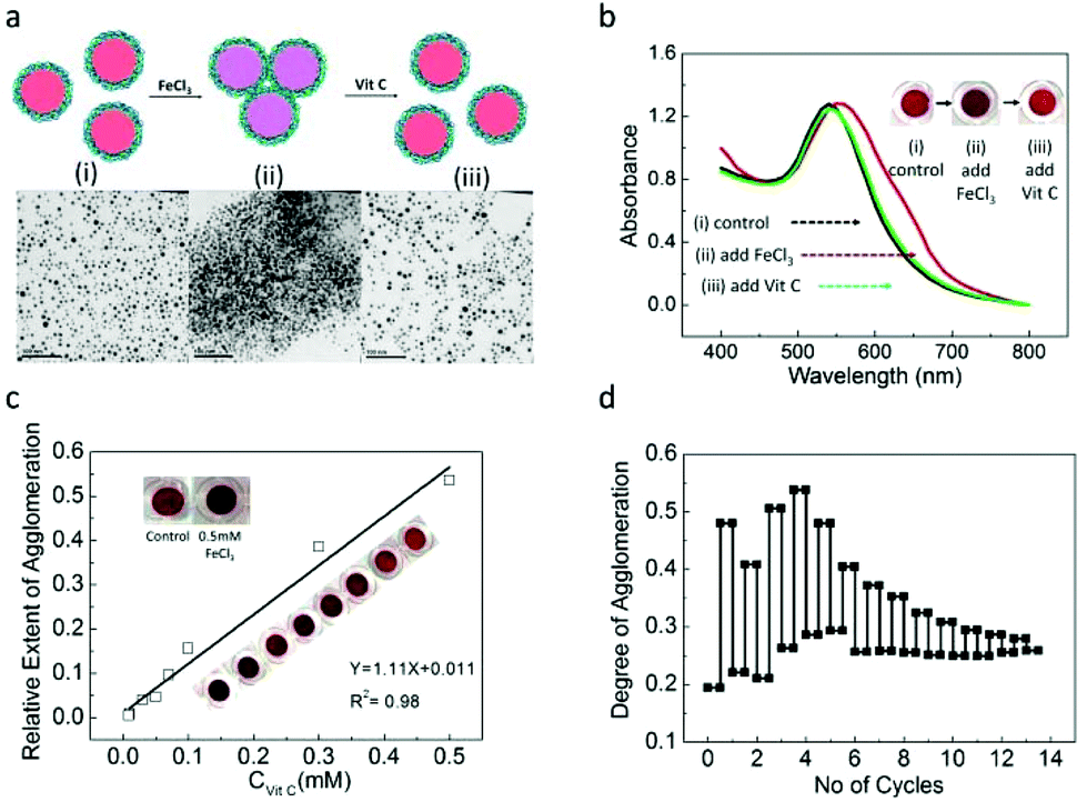 | ||
| Fig. 4 (a) Schematic illustration of the assay principle for detecting oxidizing (FeCl3) and reducing (Vit C) agents using PFS−@AuNP colorimetric probes, and TEM images of the (i) PFS−@AuNPs (control), (ii) after the addition of 0.5 mM FeCl3 to the PFSox−@AuNPs, and (iii) after the addition of 0.5 mM Vit C to the FeCl3 treated Vit C solution. (b) UV-Vis spectra of (i), (ii), (iii); inset 2b shows the sequential color changes of the respective PFS−@AuNP solution (from i to iii). (c) Plot of the relative extent of aggregation (induced by the fixed concentration of FeCl3) as a function of varying concentration of Vit C. (d) Repeatability test of the PFS−@AuNP colorimetric assay test. | ||
In the colorimetric assay for the detection of Vit C, 0.5 mM of FeCl3 was first added to a series of samples containing a fixed amount of PFSox−@AuNPs, followed by the progressive addition of Vit C at a constant time interval. The absorbance ratio values obtained at two wavelengths (A650/A530) was used to quantify the degree of aggregation, ψ. The relative extent of the aggregation was defined as ε = ψ(PFSox−@AuNPs + Vc)/ψ(PFSox−@AuNPs). Fig. 4c shows the values of ε as a function of varying concentrations of Vit C used. As is shown, the relative extent of aggregation is a linear function of Vit C concentration, and provides calibration for the sensing assay. The detection limit (DOL) for Vit C was found to be 0.01 mM. Interestingly, the effect of redox reaction-induced aggregation of PFS−@AuNPs is reversible, which can enable the repeatable use of this colorimetric probe for detecting the redox reaction in a one pot solution. Fig. 4d shows the degree of aggregation of the nanoparticle versus the number of cycles. As can be seen, the sensor remains useable for 13 repeated sensing events. The reason for decreasing the difference as observed with the increasing number of sensing cycles is related to the overall growth of the concentration of the oxidizing and reducing agents in the assay.
Meanwhile, interference factors such as temperature, pH and the effects of introducing other substances have been studied (ESI, Fig. S3–S5†). PFS− is not a pH sensitive and temperature sensitive polyelectrolyte. The synthesized PFS−@AuNPs are stable in 60 °C aqueous solution or in the solutions with a pH range from 2 to 10. In some “inert” bio-substances, such as L-lysine, galactose, and horseradish peroxidase, the particles maintain their redox responsiveness for Vit C detection.
Other kinds of redox reagents fulfill the following requirements: (a) the oxidant of the ferrocene unit or the reducing agent of the ferrocenium unit; (b) no additional linkage formation between the particles and redox reagents can be detected by this colorimetric method (ESI Fig. S6†). To further verify the usefulness of this sensing system, other experimental studies that focus on enhancing the detection sensitivity and selectivity, and the detection of Vit C serum are currently underway.
Conclusions
In summary, we presented an easy and effective one-step process for the preparation of redox-responsive AuNPs capped with stabilizing PFS polyelectrolytes. The PFS polyions featured either positively or negatively charged side-groups. PFS was employed as a reducing agent and as a stabilizer. By judicious design and control of experimental parameters such as the concentration ratio of Fc and AuCl4−, ionic strength of NaCl, and the type of charges of PFS, PFS@AuNPs were synthesized with a controlled size and stability. In addition, redox-responsive PFS−@AuNPs with localized SPR nanostructures provided a unique tunable color and UV-Vis spectral parameters, as well as reversible redox kinetics. We indicate possible applications for the colorimetric detection of other oxidizing and reducing agents in a one-pot solution using Vit C as a model substance.Conflicts of interest
There are no conflicts to declare.Acknowledgements
We are grateful to the A*STAR (Agency for Science, Technology and Research), Singapore for providing financial support.Notes and references
- H. Bönnemann and R. M. Richards, Eur. J. Inorg. Chem., 2001, 2455–2480 CrossRef.
- M. De, P. S. Ghosh and V. M. Rotello, Adv. Mater., 2008, 20, 4225–4241 CrossRef CAS.
- M. Grzelczak, J. Vermant, E. M. Furst and L. M. Liz-Marzán, ACS Nano, 2010, 4, 3591–3605 CrossRef CAS PubMed.
- J. M. Pingarrón, P. Yáñez-Sedeño and A. González-Cortés, Electrochim. Acta, 2008, 53, 5848–5866 CrossRef.
- M. Pumera, S. Sánchez, I. Ichinose and J. Tang, Sens. Actuators, B, 2007, 123, 1195–1205 CrossRef CAS.
- R. Sardar, A. M. Funston, P. Mulvaney and R. W. Murray, Langmuir, 2009, 25, 13840–13851 CrossRef CAS PubMed.
- Y. Tang and W. Cheng, Sci. Adv. Mater., 2012, 4, 784–797 CrossRef CAS.
- J. L. West and N. J. Halas, Annu. Rev. Biomed. Eng., 2003, 5, 285–292 CrossRef CAS PubMed.
- M. Haruta and M. Daté, Appl. Catal., A, 2001, 222, 427–437 CrossRef CAS.
- S. Guo and E. Wang, Anal. Chim. Acta, 2007, 598, 181–192 CrossRef CAS PubMed.
- P. Zhao, N. Li and D. Astruc, Coord. Chem. Rev., 2013, 257, 638–665 CrossRef CAS.
- P. Alexandridis, Chem. Eng. Technol., 2011, 34, 15–28 CrossRef CAS.
- G. Palui, S. Ray and A. Banerjee, J. Mater. Chem., 2009, 19, 3457–3468 RSC.
- J. K. Stolarczyk, A. Deak and D. F. Brougham, Adv. Mater., 2016, 28, 5400–5424 CrossRef CAS PubMed.
- T. Gillich, C. Acikgöz, L. Isa, A. D. Schlüter, N. D. Spencer and M. Textor, ACS Nano, 2013, 7, 316–329 CrossRef CAS.
- M. S. Yavuz, W. Li and Y. Xia, Chem. – Eur. J., 2009, 15, 13181–13187 CrossRef CAS PubMed.
- W. Schärtl, Nanoscale, 2010, 2, 829–843 RSC.
- M. Q. Zhu, L. Q. Wang, G. J. Exarhos and A. D. Q. Li, J. Am. Chem. Soc., 2004, 126, 2656–2657 CrossRef CAS PubMed.
- J. M. Tam, J. O. Tam, A. Murthy, D. R. Ingram, L. L. Ma, K. Travis, K. P. Johnston and K. V. Sokolov, ACS Nano, 2010, 4, 2178–2184 CrossRef CAS PubMed.
- Y. Yan, J. I. L. Chen and D. S. Ginger, Nano Lett., 2012, 12, 2530–2536 CrossRef CAS PubMed.
- X. Xie, W. Xu and X. G. Liu, Acc. Chem. Res., 2012, 45, 1511–1520 CrossRef CAS PubMed.
- E. Tan, J. Wong, D. Nguyen, Y. Zhang, B. Erwin, L. K. Van Ness, S. M. Baker, D. J. Galas and A. Niemz, Anal. Chem., 2005, 77, 7984–7992 CrossRef CAS PubMed.
- G. Song, C. Chen, J. S. Ren and X. G. Qu, ACS Nano, 2009, 3, 1183–1189 CrossRef CAS PubMed.
- X. Liu, Y. Yang and M. W. Urban, Macromol. Rapid Commun., 2017, 38 Search PubMed , 1700030.
- F. Li, J. Lu, X. Kong, T. Hyeon and D. Ling, Adv. Mater., 2017, 29 Search PubMed , 1605897.
- S. T. Camli, F. Buyukserin, C. T. Yavuz and M. S. Yavuz, Mater. Chem. Phys., 2012, 134, 1153–1159 CrossRef CAS.
- L. Sun, D. Zhao, M. Ding, H. Zhao, Z. Zhang, B. Li and D. Shen, J. Mater. Sci. Technol., 2013, 29, 613–618 CAS.
- P. Alexandridis and M. Tsianou, Eur. Polym. J., 2011, 47, 569–583 CrossRef CAS.
- K. Kulbaba and I. Manners, Macromol. Rapid Commun., 2001, 22, 711–724 CrossRef CAS.
- R. L. N. Hailes, A. M. Oliver, J. Gwyther, G. R. Whittell and I. Manners, Chem. Soc. Rev., 2016, 45, 5358–5407 RSC.
- N. G. Connelly and W. E. Geiger, Chem. Rev., 1996, 96, 877–910 CrossRef CAS PubMed.
- D. Jańczewski, J. Song and G. J. Vancso, Eur. Polym. J., 2014, 54, 87–94 CrossRef.
- D. Fichou, G. Horowitz and F. Garnier, Synth. Met., 1990, 39, 125–131 CrossRef CAS.
- A. C. Arsenault, H. Míguez, V. Kitaev, G. A. Ozin and I. Manners, Adv. Mater., 2003, 15, 503–507 CrossRef CAS.
- M. I. Giannotti, H. Lv, Y. Ma, M. P. Steenvoorden, A. R. Overweg, M. Roerdink, M. A. Hempenius and G. J. Vancso, J. Inorg. Organomet. Polym., 2005, 15, 527–540 CrossRef CAS.
- L.-z. Zhu, W.-b. Zhou and J. Ji, J. Nanopart. Res., 2010, 12, 2179–2187 CrossRef CAS.
- X. L. Feng, H. R. Wu, X. F. Sui, M. A. Hempenius and G. J. Vancso, Eur. Polym. J., 2015, 72, 535–542 CrossRef CAS.
- B. Zoetebier, M. A. Hempenius and G. J. Vancso, Chem. Commun., 2015, 51, 636–639 RSC.
- X. Sui, X. Feng, A. Di Luca, C. A. van Blitterswijk, L. Moroni, M. A. Hempenius and G. J. Vancso, Polym. Chem., 2013, 4, 337–342 RSC.
- A. Rapakousiou, C. Deraedt, H. Gu, L. Salmon, C. Belin, J. Ruiz and D. Astruc, J. Am. Chem. Soc., 2014, 136, 13995–139958 CrossRef CAS PubMed.
- M. A. Hempenius, F. F. Brito and G. J. Vancso, Macromolecules, 2003, 36, 6683–6688 CrossRef CAS.
- I. Manners, Adv. Organomet. Chem., 1995, 37, 131–168 CrossRef CAS.
- Q. Yang, L. Wang, W. D. Xiang, C. L. Wang and J. F. Zhou, Prog. Chem., 2006, 18, 290–297 CAS.
- Y. Zhang, Y. Shen, X. Yang, S. Sheng, T. Wang, M. F. Adebajo and H. Zhu, J. Mol. Catal. A: Chem., 2010, 316, 100–105 CrossRef CAS.
- T. Kim, C.-H. Lee, S.-W. Joo and K. Lee, J. Colloid Interface Sci., 2008, 318, 238–243 CrossRef CAS PubMed.
- M. A. Hempenius, C. Cirmi, J. Song and G. J. Vancso, Macromolecules, 2009, 42, 2324–2326 CrossRef CAS.
- C. Engelbrekt, P. S. Jensen, K. H. Sorensen, J. Ulstrup and J. Zhang, J. Phys. Chem. C, 2013, 117, 11818–11828 CAS.
- Y. N. Tan, J. Y. Lee and D. I. C. Wang, J. Am. Chem. Soc., 2010, 132, 5677–5686 CrossRef CAS PubMed.
- Y. N. Tan, J. Y. Lee and D. I. C. Wang, J. Phys. Chem. C, 2008, 112, 5463–5470 CAS.
- M. Y. Lin, H. M. Lindsay, D. A. Weitz, R. C. Ball, R. Klein and P. Meakin, Nature, 1989, 339, 360–362 CrossRef CAS.
- Z. Y. Zhang, S. Maji, A. B. D. Antunes, R. De Rycke, Q. L. Zhang, R. Hoogenboom and B. G. De Geest, Chem. Mater., 2013, 25, 4297–4303 CrossRef CAS.
- Y. Wang, P. Zhang, X. Mao, W. Fu and C. Liu, Sens. Actuators, B, 2016, 231, 95–101 CrossRef CAS.
- A. Hayat, B. Gonca and S. Andreescu, Biosens. Bioelectron., 2014, 56, 334–339 CrossRef CAS PubMed.
- G. Wang, Z. Chen and L. Chen, Nanoscale, 2011, 3, 1756–1759 RSC.
Footnotes |
| † Electronic supplementary information (ESI) available. See DOI: 10.1039/c7nr04697a |
| ‡ Permanent address: MESA+ Institute for Nanotechnology, Materials Science and Technology of Polymers, University of Twente, P.O. Box 217, 7500 AE Enschede, The Netherlands. |
| This journal is © The Royal Society of Chemistry 2017 |