
 Open Access Article
 This Open Access Article is licensed under a
 Creative Commons Attribution 3.0 Unported Licence
Towards in situ determination of 3D strain and reorientation in the interpenetrating nanofibre networks of cuticle†
Y.
Zhang‡
ab,
P.
De Falco‡
a,
Y.
Wang
a,
E.
Barbieri
a,
O.
Paris
c,
N. J.
Terrill
 d,
G.
Falkenberg
b,
N. M.
Pugno
eaf and
H. S.
Gupta
*a
d,
G.
Falkenberg
b,
N. M.
Pugno
eaf and
H. S.
Gupta
*a
aQueen Mary University of London, Institute of Bioengineering and School of Engineering and Material Science, London, E1 4NS, UK. E-mail: h.gupta@qmul.ac.uk
bPhoton Science, Deutsches Elektronen-Synchrotron DESY, Hamburg, Germany
cInstitute of Physics, Montanuniversitaet Leoben, Leoben, Austria
dDiamond Light Source, Harwell Science and Innovation Campus, Harwell, UK
eLaboratory of Bio-Inspired & Graphene Nanomechanics, Department of Civil, Environmental and Mechanical Engineering, University of Trento, Via Mesiano, 77, 38123, Trento, Italy
fKet Lab, Edoardo Amaldi Foundation, Italian Space Agency, Via del Politecnico snc, 00133, Rome, Italy
First published on 19th July 2017
Abstract
Determining the in situ 3D nano- and microscale strain and reorientation fields in hierarchical nanocomposite materials is technically very challenging. Such a determination is important to understand the mechanisms enabling their functional optimization. An example of functional specialization to high dynamic mechanical resistance is the crustacean stomatopod cuticle. Here we develop a new 3D X-ray nanostrain reconstruction method combining analytical modelling of the diffraction signal, fibre-composite theory and in situ deformation, to determine the hitherto unknown nano- and microscale deformation mechanisms in stomatopod tergite cuticle. Stomatopod cuticle at the nanoscale consists of mineralized chitin fibres and calcified protein matrix, which form (at the microscale) plywood (Bouligand) layers with interpenetrating pore-canal fibres. We uncover anisotropic deformation patterns inside Bouligand lamellae, accompanied by load-induced fibre reorientation and pore-canal fibre compression. Lamination theory was used to decouple in-plane fibre reorientation from diffraction intensity changes induced by 3D lamellae tilting. Our method enables separation of deformation dynamics at multiple hierarchical levels, a critical consideration in the cooperative mechanics characteristic of biological and bioinspired materials. The nanostrain reconstruction technique is general, depending only on molecular-level fibre symmetry and can be applied to the in situ dynamics of advanced nanostructured materials with 3D hierarchical design.
1. Introduction
In the design of advanced functional composites, a key characteristic is the assembly (either via self-organization or guided deposition) of sub-micron elements such as nanowires or nanofibres into a hierarchical and ordered system at multiple length scales between the molecular and microscopic levels. These include mineralized collagen fibrils in bone,1 ordered calcite nanocrystals in hierarchical clay nanocomposites,2,3 ordered 2D materials inside 3D biomineralized materials,4 mechanically high performance polymer/nanoclay composites,5 oriented TiO2 nanocrystals assemblies for photocatalysis,6 and semiconductor nanocrystals in superlattices.7 The precise orientation, strain and structure of the nanoscale inclusions in such systems is a crucial determining factor in enabling function and influencing a diverse range of designed material properties, including mechanics,4,8,9 catalytic performance or semiconductor performance.7 In this regard, advances in X-ray techniques including scanning nano-diffraction, ptychography and coherent X-ray diffraction have been applied to determine the strain, shape and texture of individual nanoparticles or composite aggregates.10–12However, an implicit assumption of much current X-ray scanning microprobe and in situ methods is a neglect of the depth dimension in the analysis of 2D diffraction maps. The 2D X-ray diffraction pattern obtained is a slice through the 3D reciprocal space intensity distribution.13 This limits the application of most such methods to simple in-plane geometries or sections or special materials such as collagen fibrils with an ordered periodic structure at the nanoscale, while in most real-life systems, the 3D morphology may have no particular symmetry or alignment to sample shape. While recent innovative methods like 3D small-angle X-ray scattering (SAXS) tomography14 and polychromatic X-ray diffraction,15,16 which reconstruct 3D reciprocal space intensity in a model-free manner, circumvent this 2D limitation, these methods have limitations for in situ studies. SAXS tomography can take several hours of synchrotron time per reconstruction,14 and the polychromatic X-ray diffraction analysis requires several minutes with a specialized energy-dispersive detector,15 or scanning the photon energy. 3D X-ray structural microscopy uses polychromatic radiation to measure grain orientation and strain in functionally graded materials and composites, but requires sample rotation.17 Indeed, the in situ dynamics of the nanoscale inclusions can follow a complex and non-predetermined path of coupled rotation, stretching and phase transformation in 3D, and requires time-resolutions of the order of seconds or below, and do not readily allow steps such as sample-rotation or energy scanning at each step of the process.14,18 Further, methods such as ptychography are suited for scanning with high (a few tens of nanometres) resolution to obtain structure information, but are also comparatively time consuming due to overlapping scans and are therefore not suited for in situ studies of samples in the millimetre size range.12 There is therefore a significant need for multiscale 3D reconstruction methods for in situ nanoscale mechanics. This need is especially relevant for biological and biomimetic composites, where the hierarchical architecture leads to complex, multi-dimensional motifs.9
A prototypical example of such a multiscale biocomposite (ESI, Fig. S1†) is the crustacean cuticle.19,20 At the nanoscale, the cuticle may be considered a three-phase composite of ∼3 nm diameter chitin fibrils, crosslinked amorphous proteins and biogenic mineral (calcium carbonate), along with water. The mineralized fibrils aggregate into fibres at the scale of ∼100 nm, which in turn form a characteristic continuous rotated layered plywood structure at the scale of ∼10 μm, known as the Bouligand motif.21 A network of pore canal fibres run perpendicular to these Bouligand layers, forming an interpenetrating network of nanofibers which has been likened to a honeycomb structure.19 This structural motif has evolved into a range of functional specializations, from impact resistant exoskeletons like the dactyl and telson in the mantis shrimp, to hyper-extensible appendages for laying eggs,22 to specialized sensory organs in spiders.23 In particular, the exoskeleton of the mantis shrimp has attracted considerable recent attention, due to its ability to resist high rate, repetitive loading with no structural damage serving as a template for bioinspired composites.24–28 While multiscale modelling studies of the (lobster) cuticle exist, suggesting that much of the variation of mechanical properties arises due to structure at the microscale and above,29 there is little direct experimental in situ evidence of the nanoscale and microscale mechanisms in crustacean cuticle.
In this paper, we develop and apply an in situ multiscale X-ray diffraction/modelling scheme to determine the nanoscale and microscale deformation mechanisms in crustacean cuticle. By modelling the crustacean cuticle extracellular matrix as two interpenetrating fibre-lamellate structures at the sub-micron scale, we predict the 3D X-ray diffraction intensity distributions from these fibres using an asymptotic integral approach.30 Under mechanical load, these distributions will alter in a manner dictated by the coupled effects of strain at the nanoscale along with 3D deformation and reorientation at larger scales. We show how, by modelling the fibre-level stress and strain fields by matching lamination theory to the experimental X-ray peak shifts,31 and subsequently accounting for larger mesoscale (>10 μm) deformations at the scale of lamellae and interpenetrating fibre distributions, we can determine the in situ nano- and microscale mechanics of crustacean cuticle with high precision. Our approach – solely relying on the existence of fibre symmetry at the molecular level – is designed to apply to in situ studies of the structural dynamics of nanoscale inclusions in advanced multiscale functional materials, provides both mechanical strain as well as structural reorientation, and can be carried out using standard 2D X-ray detectors or lab-setups.
2. Ultrastructural model and experimental results
2.1. Analytic 3D X-ray diffraction intensity distributions for interpenetrating nanofibre networks
Fig. 1 shows the experimental protocol for in situ tensile testing during synchrotron XRD experiment, and the relation of X-ray diffraction geometry to the underlying nanofibre organization. Tergite specimens from the stomatopod (Fig. 1a) cuticle embedded in two orthogonal orientations (Fig. 1b) are deformed during synchrotron XRD (Fig. 1c), leading to the acquisition of a series of XRD patterns (for details see Materials and methods). The microstructure of cuticle consists of in-plane fibres in a twisted plywood arrangement known as Bouligand layers (green fibres, Fig. 1d), interpenetrated with perpendicularly oriented pore-canal fibres (blue fibres, Fig. 1d). The basic microstructural unit in each scattering volume element is therefore a combination of in-plane fibres (IP) (forming Bouligand plywood layers) and bundles of out-of-plane (OP) fibres (from the pore-canals) (Fig. 1d).32 Here, we consider both micro units as variations of an underlying planar fibre distribution w(γ;γ0,Δγ0) (Fig. 1e and Table S1-II†), with the Bouligand (IP-) phase corresponding to fibres equally oriented in all directions in the lamellar plane, and the pore-canal (OP-) fibres oriented principally in one direction (along the pore). As the plane of the fibres in the sample may be oriented at nonzero angles to the principal coordinate axes of the lab-frame, we denote α and β (with respect to qLz and qLy axis respectively) as the Euler tilt angles of the plane with respect to the lab coordinate system (Fig. S3†).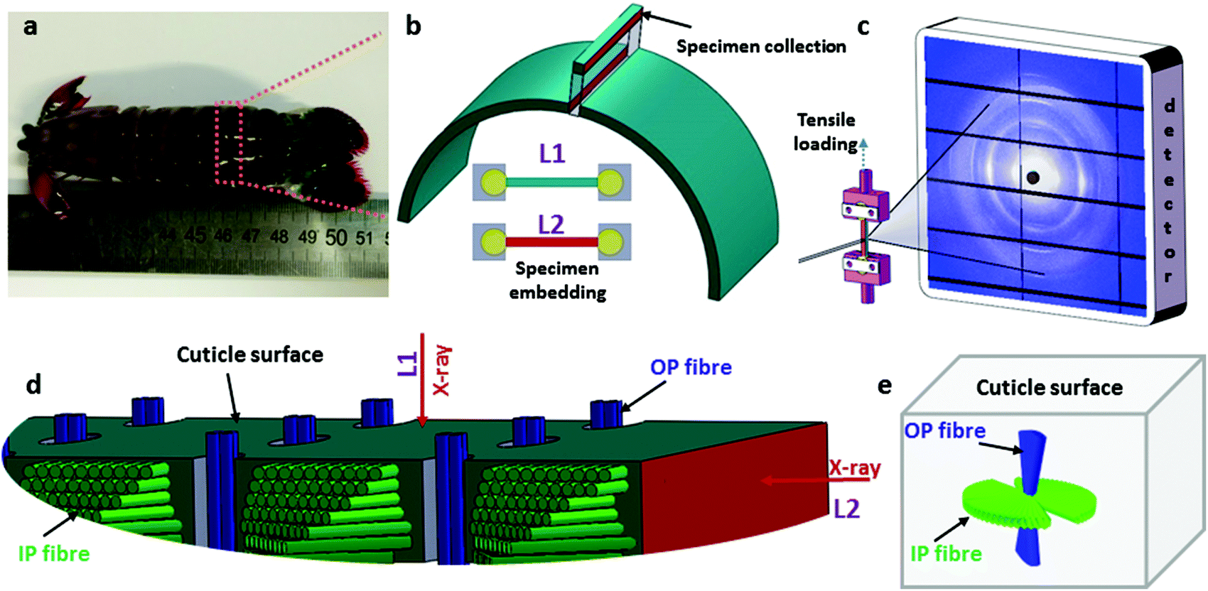 | ||
| Fig. 1 Stomatopod tergite cuticle and experimental in situ XRD protocol. (a) Image of a stomatopod. (b) Schematic of a single abdominal segment, which is sectioned into tensile test sections along the long axis of the animal. Lower schematics show the tensile test sample embedded in dental cement, with the direction of X-ray beam into the page. The two colour codes (blue and dark red; colour online) indicate different faces of the cuticle. Blue is normal to the cuticle surface, and red is the plane parallel to the cuticle surface. The rectangular-shaped sections are oriented in two directions when embedded in the dental cement holders (L1: X-ray normal to cuticle surface and L2: X-ray parallel to cuticle surface). (c) Schematic of in situ tensile testing of cuticle specimens during synchrotron XRD, with example 2D XRD pattern on detector. The specimen was hydrated in artificial sea water during the in situ testing. (d) Higher magnifications schematic of the cuticle section, showing the relation of the X-ray beam to the fibrous microstructure in the L1- and L2-configurations. Green fibre layers (colour online) represent the twisted plywood Bouligand lamellae (in-plane or IP-fibres), and blue cylinders the chitin fibres in the pore-canals running perpendicular to the cuticle surface (out-plane or OP-fibres). (e) The foregoing schematic is simplified to show the two groups of fibre distributions inside a scattering volume, and their orientation with regards to the cuticle surface. | ||
These micro-units are themselves comprised – at the nanoscale – of chitin fibres,29 made of α-chitin molecules arranged in a fibre-symmetric manner around the fibre axis (Fig. S1†). As a consequence, the diffraction intensity of the (hk0) reflections (such as the equatorial (110) peak) can be represented in reciprocal space as rings,33 and the (00l) reflections (such as the (002) peak) as paired spots. To justify the assumption of fibre symmetry, some discussion of the size of the X-ray scattering volume relative to the micro- and nanostructural building blocks is needed. Specifically, cuticle fibre symmetry is believed to hold at the fibre-level (100–300 nm or 0.1–0.3 μm in diameter) and above.19,32 The scattering volume in our experiments is given by the product of the beam cross-sectional area (10 μm × 10 μm) with the sample thickness (∼500 μm), and can be seen to be much larger than the fibre dimensions, and hence the material can be considered as having fibre symmetry at the scale of the measurements. The assumption of fibre symmetry may, however, break down for very small scattering volumes – smaller than single fibres – such as with nanofocus X-ray beams and submicron thick samples. To show the intensity distribution on the reciprocal space as a function of 3D orientation, a polar-sphere-like representation is used. The X-ray diffraction (XRD) intensity pattern corresponding to the model will be the 2D Ewald surface intersection with 3D volume of reciprocal space scattering intensity (Fig. S2†). Different spheres correspond to different reflections, and the spherical intensity variation correlates to the 3D orientation distributions of IP and OP fibres. As the full 3D intensity variation on the different reciprocal spheres cannot be fully captured using a 2D detector at a single orientation, here we used two orthogonal tensile test geometries together with modelling to fully capture the deformation and reorientation information for both IP and OP fibres (Fig. 1b and d). Both the (002) and (110) reflections can be used to calculate the axial and radial fibrillar deformation respectively as well as orientation for the chitin fibres, but in this initial work we present results only on the (002) reflection.
Fig. 2a show the geometry of IP and OP fibres in the L1 configuration. Fig. 2b shows how, for the (110) reflection, constructive interference of the (hk0) rings from the IP fibres leads to peaks only at the poles perpendicular to the intersection plane between QS(110) sphere and Ewald sphere.33,34 Therefore, the intensity variation of (110) reflection from the major fibre component (IP) is not captured by the detector.33 Concurrently, for the (002) reflection, the paired diffraction spots from individual fibres lead to rings parallel to the qy–qz plane due to the Bouligand distribution of the IP fibres (Fig. 2c). In this study, we will use the (002) reflection to calculate the deformation and reorientation of IP fibres in the L1 configuration.
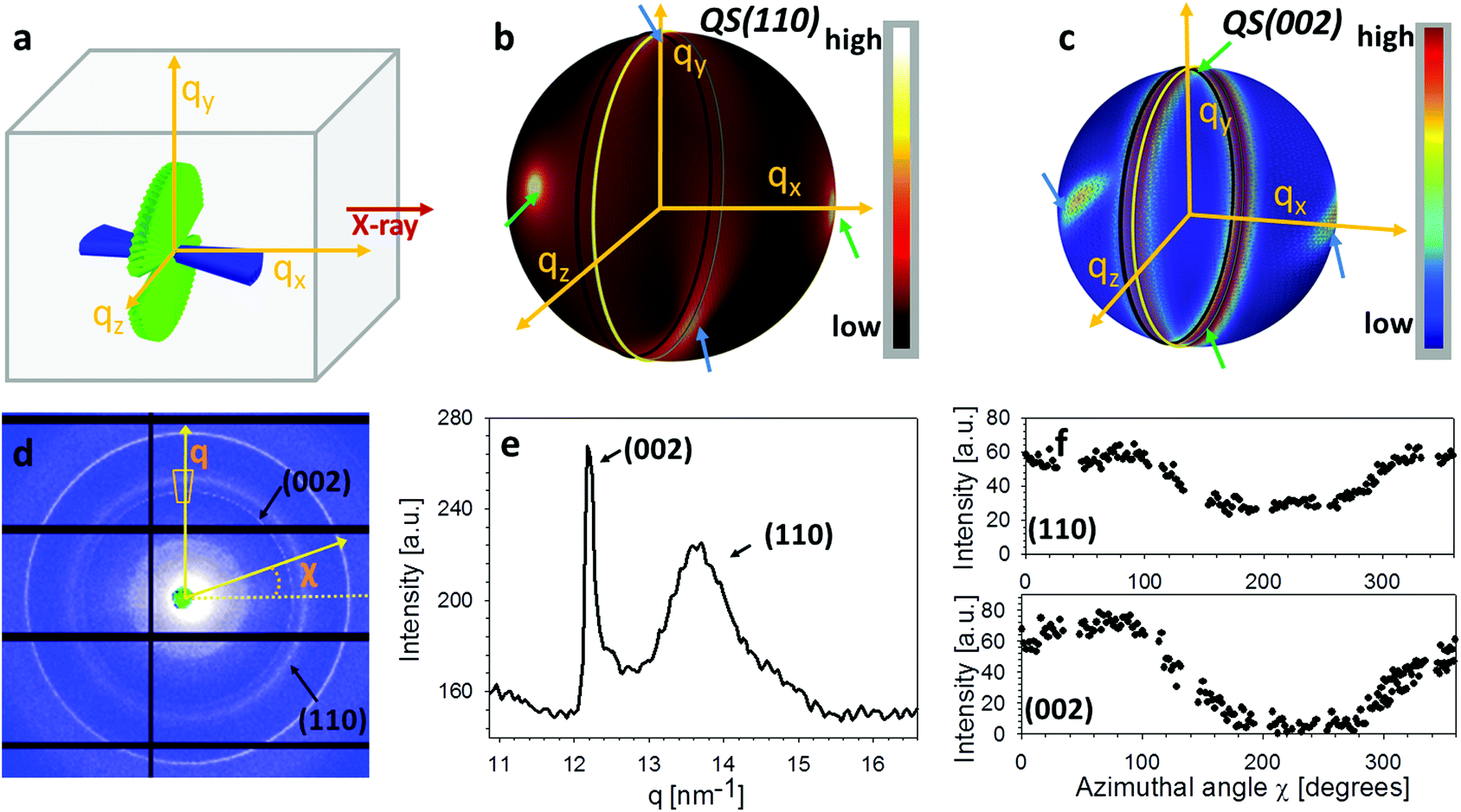 | ||
| Fig. 2 Diffraction data analysis. (a) Schematic showing the in-plane and out-of-plane chitin fibre distributions inside cuticle for L1 configuration (rotated by 90° with respect to Fig. 1a5†). (b) From the combined fibre distributions, the predicted intensity distributions of the (110) reciprocal lattice vector on a 3D sphere, based on the model described in section 2. (c) Likewise, the model-based intensity distributions of the (002) reciprocal lattice vector on a 3D sphere. (d) A representative experimental 2D diffraction pattern from tergite cuticle (L1 configuration). Both (110) and (002) reflections from alpha chitin are indicated. (e) Azimuthally averaged intensity profiles showing the sharp (002) and broad (110) peaks. (f) Radially averaged azimuthal profiles for (002) and (110) reflections, showing non-uniform angular texture. | ||
These complex distributions in reciprocal space can be represented analytically. Consider the Bouligand lamella to be oriented in the qLy − qLz plane (indicated with green fibres in Fig. 2a). For a single fibre, the intensity distribution in reciprocal space can be written as (ESI†):
 | (1) |
 , Θ the Bragg diffraction angle for the (002) Miller index and Δq(002) the width of the (002) ring in reciprocal space (an analogous expressions for the (110) reflection is given in ESI†). The full XRD intensity is obtained by a weighted integration of the intensity in eqn (1) over all possible fibre angles in the lamella, and these 3D spherical intensity distributions are plotted in Fig. 2b and c. To obtain the intensity profile on the detector, the 3D reciprocal space distribution is transformed to 2D detector coordinates (q,χ) (transformation equations in ESI, Table V†). For a uniform fibre distribution w(γ;γ0,Δγ0) = w0 in the lamellar plane (which represents Bouligand lamellae with fibres in the sub-lamellae at all possible angles), by taking the asymptotic limit of small Δq(002), it is possible to obtain a closed form of the azimuthal intensity profile:
 | (2) |
In the aligned state (where α = β = 0°) and the Bouligand plane is parallel to the lab-frame, it is clear that the intensity of the (002) ring will be constant as a function of azimuthal angle χ, with a value of:
 | (3) |
In Fig. 2d an example 2D XRD pattern is shown in the L1-orientation, with the (002) and (110) reflections indicated, whose peaks are shown on a radial profile in Fig. 2e. Azimuthally resolved intensity plots are shown for these reflections in Fig. 2f. A ring background subtraction was used to eliminate the diffuse mineral scattering background Ibgr in the WAXD pattern using Ibgr(χ;q0) = (I(χ;q0 + Δq) + I(χ;q0 − Δq))/2 for both (110) and (002) reflections (Δq = 0.1 nm−1 is a small increment of wavevector such that q0 ± Δq is outside of the Bragg peak in each case). A clear angular variation of intensity is observed in both subplots, which, when taken together with Fig. 2b and c, implies slight nonzero value of the tilt angles α and β, and these tilts will be quantitatively determined in the following subsections. Shifts in the (002) peak positions (Fig. 2e) will (in an angularly resolved sense to be described in the next section) be linked to the strain along the fibre axis (εf) induced by the tensile loading.
When the cuticle is deformed, a priori expectations are that the fibre distributions (both IP and OP) will undergo both (i) nanoscale axial deformation along the fibres and reorientation of the fibres in the Bouligand plane (changing the planar fibre distribution w(γ;γ0,Δγ0)), as well as (ii) an overall angular movement of the Bouligand layer itself (change in α and β) at the mesoscale. While the analytic relations given previously are applicable in the general case, for the specific case considered here, where the fibre plane is nearly aligned with the lab-principal axes, we can proceed via a simpler two-step approximation. First, given that the Euler tilt angles α and β are small to start with, the deformation of the fibres in the Bouligand plane can be obtained from the 2D XRD pattern in the same manner as would be for an un-tilted configuration. This step will provide the nanoscale strain and reorientation, and enable us to track the change in the fibre orientation distribution during the loading process, and is described in the next subsection.
2.2. Fibre mechanics in the Bouligand lamellae match laminate theory predictions at nanoscale
An averaged tensile stress–strain curves for the tergite cuticle is shown in Fig. 3a, showing a linear increase of tissue stress with strain with a slight downward curvature evident at strains >0.6–0.8%. Concurrently, the radial peak profiles for the (002) reflection show shifts; for the direction parallel to the loading direction, to smaller wavevector (Fig. 3b) implying a tensile deformation of the chitin fibres. Fig. 3c shows the schematic of the plywood lamellae. The strain in the different sublayers of the Bouligand lamellae was calculated from shifts in the angularly resolved profiles of the (002) peak, and plotted in Fig. 3d. The result shows that chitin fibres which orientated close to the tensile direction (ψ = 0°–40°) exhibit a positive strain as the stress increases, while fibres orientated further away (60°–90°) from the tensile direction showed a negative strain (Fig. 3d). In the transition region (40°–60°) the chitin fibres showed no significant strain increments compared to the other regions. The experimental data appear to lie in three groups (0–40°: tension, 50–60°: no change; 70–90°: compression), rather than the continuous change in Fig. 3, but this effect is largely due to the experimental scatter in the fitted data. | ||
| Fig. 3 In-plane deformation and reorientation of chitin nanofibres under L1 tensile configuration. (a) An average stress and strain curve obtained from tensile tests. The results were averaged from five specimens. (b) Shifts in position of the (002) peak to smaller wavevector during tensile testing, showing elongation under tensile load. (c) Schematic representing the different sublamellae, parameterized by the angle ψ = 90° − χ. (d) The anisotropic experimental fibre strain (εf) from sublamellae oriented at differentψ, ranging from 0° to 90°, as a function of the increasing applied tissue stress (σT). Tensile deformation of fibres along the loading direction (ψ ∼ 0°) and compression of fibres perpendicular to the loading direction (ψ near 90°) were observed. (e) Angularly resolved fibre strains predicted from a laminate model of the Bouligand layer (section 2.2 and ESI, section S3†), showing a similar trend as the experimental data. (f) Lamina reorientation calculated from the model (ESI, section S3†), showing maximum fibre reorientation at ψ = 45°. Extent of fibre reorientation is very small (<0.1° at maximum). | ||
The in-plane deformation and reorientation then were calculated using classical lamination theory to compare with the experimental results obtained from WAXD patterns. The plywood structured tergite sample was treated as a laminate comprising 100 Bouligand sublayers (laminae). The reinforcement (fibre) was considered to be the mineralized chitin fibre, and the surrounding interfibrillar phase (matrix) was taken to be the mineral–protein composite. The fibre orientation in different laminae rotates around the normal axis of the whole laminate to match the plywood structure of the cuticle. Using initial estimates of the chitin, mineral and protein material properties and relative volume fractions from previous work,19,35 the deformation (Fig. 3e) of each lamina inside the whole laminate,21,28 was calculated from an analytical formulation. More detailed information on the material property assignment and analytical formulae were described in ESI (section S3).† Even without any parameter fitting of the literature values to the data, good qualitative agreement is observed between Fig. 3d and e, although the deformation of the on-axis fibres is somewhat less in the experimental case than in the model. Fitting the model to the data as a function of the volume fraction, fibre moduli and other parameters is in principle possible in future work.
Generally, the fibre orientation distribution changes can be determined by tracking the angle-resolved I(χ) changes for the (002) reflection during tensile loading. The experimental results (Fig. S6a†) show that the normalized diffraction intensity is increasing in the angular region close to the tensile direction and decreasing in the angular region away to the tensile direction. However, the angle-resolved I(χ) changes can result both from in-plane fibre reorientation (from lamination theory) and the overall 3D tilting of the Bouligand lamellae. Therefore, the lamination model was used to factor out the in-plane reorientation effect.
From the modelled deformation of each lamina, it is possible to obtain the in-plane fibre reorientation (ESI, section S3,† eqn (S25)†). Under load, the angular intensity distribution is expected to narrow in width, as the fibres reorient towards the tensile axis. To describe this analytically, on application of a perturbing stress σ, a fibre originally at γ reorients to γσ according to the relation:
γσ = γ − ![[small sigma, Greek, tilde]](https://www.rsc.org/images/entities/i_char_e10d.gif) f(γ) f(γ) | (4) |
= σ/σ0 is a dimensionless perturbation parameter (σ0 = 100 MPa; as the experimentally observed ranges of stress are σT < 100 MPa, and f(γ) ≪ 1, f(γ) is a small parameter). The new angular distribution (under stress) is denoted wσ(γ;γ0,Δγ0). Using first order perturbation, conservation of fibre number, and an initially uniform fibre distribution in the cuticle lamella w0 = 1/π, it is possible to show (ESI, section S4†) that the changed distribution function is given bywσ(γ;γ0,Δγ0) ≈ w0(1 − 2B(Ec,Ep,ϕc,ϕp)cos![[thin space (1/6-em)]](https://www.rsc.org/images/entities/char_2009.gif) 2γ) 2γ) | (5) |
Bsin(2γ) which implies zero angular shift for fibres oriented parallel (γ = π/2) and perpendicular (γ = 0) to the loading direction. Using the same model parameters as used to predict the deformation of each layer, B can be calculated and the angular reorientation plotted (Fig. 3f). It turns out that in this particular material (cuticle) the in-plane reorientation and change in orientation function is very small (angular changes of the order of 0.01°).
In this way, by using the parameters from fitting the fibre deformation in Fig. 3c (with model results in Fig. 3d), we obtained the changed fibre orientation distribution function at a given stress – as long as the stress remains below the elastic limit point of validity for laminate theory. While in the particular case of cuticle considered here the change of orientation function was negligible (Fig. S6b†), in other layered composites like armored fish scales much larger reorientations have been observed via small-angle X-ray scattering.1 In general, the change in reorientation function will not necessarily be negligible in large-deformation scenarios, or in deformation of very soft materials, where the ratio between stiffness of the reinforcing fibres and the surrounding matrix is very large.36
2.3. Mesoscale reorientation shows layer alignment to tensile direction
The stress-altered fibre reorientation function wσ(γ;γ0,Δγ0) can now be inserted into eqn (2) to factor out the in-plane nanoscale reorientation, enabling the mesoscale Euler tilt angles α and β to be fitted as functions of applied stress and strain (as stated in the previous section, for cuticle the change in w(γ;γ0,Δγ0) is negligible). To show the predicted diffraction model sensitivity to the tilt angles, Fig. 4a and d show the deviation of the 2D and 1D intensity profiles (1D for (002) only) from a straight line due to nonzero but very small α = 2° (with no change in β or in the Bouligand layer fibre orientation function). Fig. 4b and e show the diffraction intensity changes with a small β tilt while α = 0°. Fig. 4c and f show that a combination of α and β tilt can split the diffraction ring. It is clearly observed that major deviations from isotropy are observed for quite small α and β angles.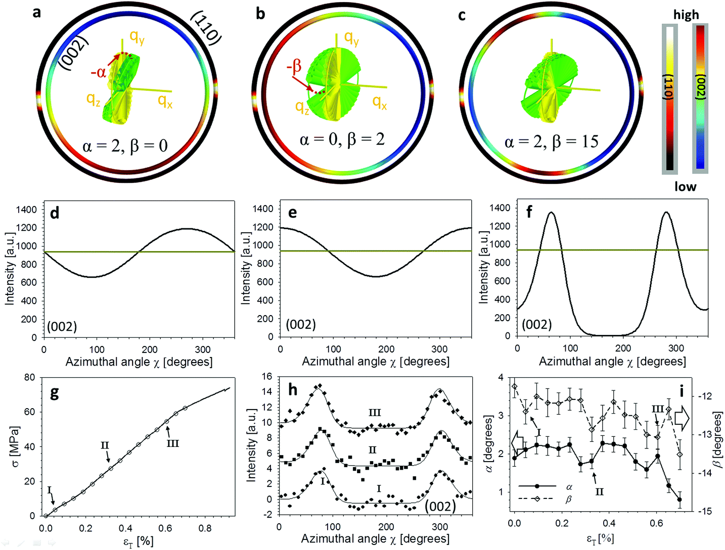 | ||
| Fig. 4 3D tilting of in-plane fibres under tensile loading. (a)–(c) The rings represent sections of the 3D spherical intensity distributions shown in Fig. 2, for both (002) (inner ring) and (110) (outer ring). Rings are colour coded for intensity levels. The different images in (a)–(c) represent different orientations (via the tilt angles α, β), shown via the schematic of the Bouligand layer (green fibres; colour online) inside the ring. Yellow axes and fibre distribution (colour online) represent the untilted (α = β = 0°) reference state. (d)–(f) Corresponding azimuthal intensity plots I(χ) for the 2D intensity sections, with the horizontal reference line in each plot denoting the untilted configuration. (g) Stress–strain curve for a representative cuticle sample, with symbols I–III denoting from where the three azimuthal intensity curves in the following section (h) are taken. (h) Azimuthal intensity plots from points I–III in (g), vertically translated for representational clarity only. Solid lines denote fits to the analytical model (eqn (2)). (i) Tilt angles α (left abscissa) and β (right abscissa) as a function of tissue strain, for the sample shown in (g), obtained by fits to the analytical model. A decrease of the off-axis tilt angle α, indicating load-induced alignment of the Bouligand layer toward the tensile axis, is observed. | ||
The qualitative reasoning for this sensitivity arises because there are two competing small parameters: the term  in eqn (2) and width Δq(002) of the (002) ring in the qx direction. Small movements of the cuticle layer will rapidly bring the intensity of the (002) ring into and out of the Ewald intersection (Fig. 3c), resulting in a high sensitivity to angular changes. This feature, though fortuitous (it would cease to hold for large reciprocal lattice vectors q or wavelength λ), is useful in practice, as the changes in the angles themselves are expected to be quite small in linear elasticity, so having large changes in the intensity distribution for small angular changes improves fit sensitivity. Fig. 4h shows the experimental I(χ) plots, and fitted curves, for three points I–III on a typical stress–strain curve of cuticle (Fig. 4g). By fitting α and β over the whole strain range (Fig. 4i), it is observed that α (denoting the deviation from the stress axis) reduces from ∼2° to >1° on application of load, with a similar change in β of about ∼1°. Such a change in α is as expected, as under tensile load the Bouligand plane would align toward the loading direction.
2.4. Pore canal fibres compress whilst Bouligand fibres extend under loading
So far, we have considered only the deformation and reorientation of the IP fibre which is the majority phase of the interpenetrating nanofiber network. The OP fibres (Fig. S1f and Fig. 1a4, a5†) interpenetrating the Bouligand layer via the transversely running pore canals will also contribute intensity on the QS(110) and QS(002) spheres. In the case of L2 geometry, the regions of (110) and (002) intensity arising from IP and OP fibre contributions are all captured in the detector (Fig. 5a and b). It is seen that the intensity peaks of (002) reflection for each phase are nearly orthogonal to each other (IP- and OP-arrows in Fig. 5c), permitting determination of peak changes in each phase individually. The 3D tilting of the lamellae plane in the L2 geometry can be directly determined using the (110) reflection and the associated model diffraction functions (ESI, Table V†).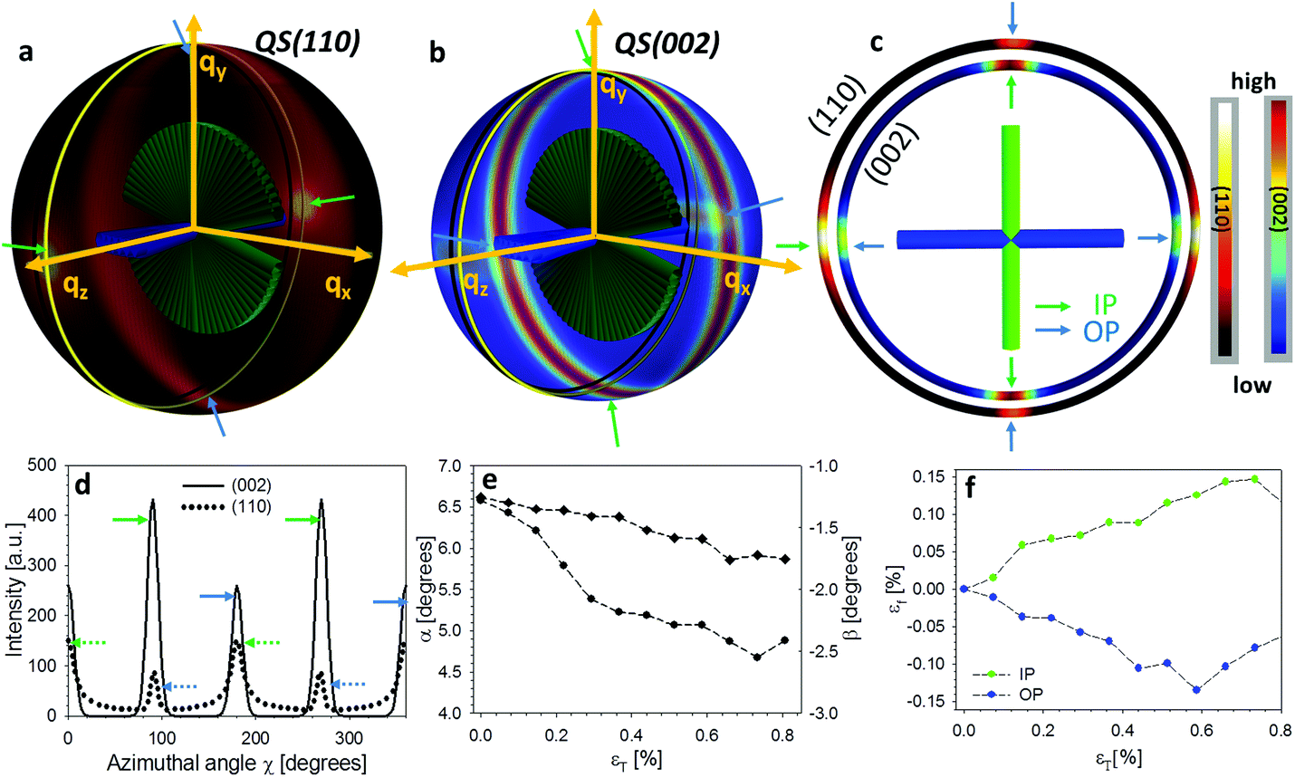 | ||
| Fig. 5 The mechanical response of out-plane fibre from L2 configuration. (a) The intensity distributions on QS(110) sphere corresponding to in-plane (green arrows) and out-of-plane (blue arrows) fibres. (b) The intensity distributions on QS(002) sphere corresponding to in-plane and out-of-plane fibres. (c) The intensity distributions of (110) and (002) reflections on the intersection plane of the Ewald sphere and QS(110) and QS(002) spheres. (d) The azimuthal intensity profile I(χ) for (110) and (002) reflections. (e) The deformation for both in-plane fibre and out-of-plane fibres as a function of tissue strain (εT) during the L2 tensile test. | ||
The trace intersection of the Ewald sphere with the reciprocal lattice spheres is shown for (002) and (110) in Fig. 5c. Fig. 5d indicates the allocation of peaks for IP and OP fibres in the I(χ) curves. In Fig. 5f, the strain increments for both pore-canal fibre and the IP fibre within the Bouligand lamellae are plotted against tissue strain. The result show that the OP fibre also exhibits a linear compressive response up to ∼−0.15% (∼0.6% tissue strain), shortly before the level at which macroscopic yielding and failure is observed (0.8%). It is clear that this phase of the nanofibre network (the pore-canal fibres) bears load and is expected to contribute to the overall mechanical properties. The corresponding reorientation dynamics of α and β deduced from the azimuthal angle changes of (110) reflection is shown in Fig. 5e, and again, reorientation of the tilt angle α to smaller values (∼6.5° to 4.5°) is observed, upon application of load.
3. Discussion and conclusion
In summary, we determined the 3D deformation and reorientation of two interpenetrating nanofiber networks in crustacean (stomatopod) cuticle, by developing a mathematical model to predict the 3D reciprocal diffraction intensity changes of (110) and (002) reflections of α-chitin fibres for two orthogonal diffraction geometries, in a combined in situ synchrotron mechanical test with X-ray diffraction. Taking advantage of the fibre symmetry, the deformation and reorientation at different hierarchical levels of the crustacean cuticle including the whole Bouligand fibre lamellae and pore-canal fibre bundles (mesoscale), each sub-lamellae (microscale) can be quantitatively determined by simple experimental design with the assist of analytical formulae. As seen in Fig. 3 and 4, we find the method is highly sensitive to both strain and angular changes as induced by stress, as the X-ray azimuthal pattern changes significantly for shifts of less than one degree, and strains are typically less than 1%.Our method clearly overcomes the limitation of 2D XRD patterns in capturing 3D diffraction intensity changes in reciprocal space through a modelling approach, whilst other structural characterization methods (reviewed in the introduction) require time-consuming sample rotations and raises concern of radiation damage to the samples. Therefore it is very suitable for in situ or in operando study in materials science, when the deformation and orientation dynamics of crystalline phase is strongly correlated to the material function. In addition, we also employed the lamination theory simulation to decouple the intensity changes due to the in-plane anisotropic strain-induced reorientation effect from changes resulting from the 3D tilt of the whole Bouligand lamellae during the tensile test (Fig. 6).
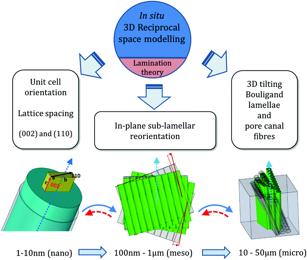 | ||
| Fig. 6 Schematic of in situ determination of 3D strain and reorientation in nanofibre networks of cuticle. Left: Molecular/nanoscale-level strain and orientation from unit-cell lattice spacing changes and c-axis direction in the chitin fibril. Middle: Correlated reorientation and strain of nanofibre layers at the mesoscale. Right: Compression of orthogonal nanofibre network in pore canals, and 3D reorientation of Bouligand lamellae. Solid arrows indicate sequence of steps in the current work; dashed arrows show the reverse procedure, which is in principle possible. | ||
One other interesting aspect of our method is that the decoupling of strain and reorientation between 2D and 3D is potentially reversible. By this we means that by obtaining the 3D reorientation information in one specific diffraction geometry (e.g. L2), the (α,β) parameters could be determined first, and accounted for in the model for I(χ) (eqn (2)), which would enable the purely in-plane deformation and reorientation to be determined. Consequently, in an inverse problem approach (analytical or numerical), the results can thereby be inserted back into (for example) lamination theory simulations to deduce the material properties of different nanoscale components. This will be very helpful in identify the material properties of components in nanostructured biocomposites like amorphous minerals or proteins which are difficult to characterize individually.
A characteristic of our approach is that it is applicable to any fibre network with molecular level fibre symmetry and (partial) crystalline order, and does not require the existence of special additional symmetries of periodicities at higher length scales (between 10–100 nm) such as in collagen.37 As such this approach is especially suitable for fibre-based biological composites. Further, the method may also be potentially extended also to highly mineralized biocomposites with relatively little organic material, such as nacre in mollusk shells,9 as long as the mineral phase is at least partly crystalline. By modelling the texture of the mineral diffraction rings similar to the manner presented here, if the sample scattering volume (and X-ray microfocus beam size) is large enough to ensure fibre symmetry of the mineral nanoscale inclusions, our approach can be adapted to model the XRD signal.
Indeed, both natural and synthetic composites comprising nanorods and nano-sheets can be considered, if partially crystalline. In such implementations, however, it must be noted that the current 2D lamellar fibre distribution w(γ;γ0,Δγ0) distribution (characteristic of the Bouligand patterns in cuticle) is a simplified case of a more general elliptical orientation distribution function in two spherical polar angles, which will be needed when considering natural composites with arbitrary 3D microstructural distribution. Hence in such cases, the two-dimensional distribution with the delta-function in the diffraction kernel (eqn (1)) will simplify to a single integral, which can be solved numerically (or approximated analytically). Complementing the in situ information from our diffraction/modelling method, for single nanorods, nanoparticles or nanosheets, methods like Bragg coherent diffraction imaging or ptychography11,12 can be used to obtain the 3D phase and strain information.
Beyond the functional analysis of biocomposites and their graded architecture,38 other examples of applications of the method can be to link 3D strain and orientation changes of the crystalline lattice of nanocomponents with the in situ or in operando mechanical, electrical, thermal, and optical performance. These may include the preferential orientation of the semi-crystalline polymer nanofibres and their correlation with piezoelectric response in energy conversion materials,39 the thermal and mechanical performance with respect to the strain and texture changes of nanoplatelets in engineering alloys,40 and the synthesis process with the resulting texture of mineral nanofibres and corresponding photocatalytic activity in environmental applications.41,42
Regarding other methods for analysis of 3D nanoscale structure in other classes of materials, we note 3D static strain and texture determinations for metal grains in thin films using scanning nano-diffraction,10,43 precession electron diffraction of strain in semiconductor quantum well structures and orientation of nanocrystals in biogenic calcite using XANES.44 Indeed, where a clear hierarchy of structural levels do not exist (in contrast to biological materials), and in situ mechanics are not needed, methods like 3D X-ray structural microscopy,18 which use sample rotation and aperture scanning, may be more appropriate. Strain evolution in nanocrystals can also be determined from coherent diffraction imaging,11 but such methods are usually focused on single particles rather than assemblies of them. Further, the approach presented here, to determine both real-time orientation and strain changes in 3D, can be applied to more complex systems even when the deformation and reorientation is small.
The angle – dependent deformation of fibres, shown to be consistent with lamination theory assuming a continuous distribution of fibre orientations, sheds light on the underlying mechanisms enabling elasticity and toughness. The tensile elongation of fibres along the loading direction, transitioning to a compression perpendicular to the load, implies a strong interconnection between sublayers in the Bouligand lamellae. These interconnections are most likely the transversely – running pore-canal fibres,19 which “stitch” the Bouligand fibre layers together. The smooth angular transition between rotating sublayers of the Bouligand structure (or sub-lamellae in the term used in bone) most likely accentuates the strong interconnection and increased toughness.24,28 Our results further highlights the mechanical importance of the pore-canal network, as a compressive strain in the pore-canal fibres, nearly equal in magnitude to the tensile strain in the Bouligand layer, is developed (Fig. 5f, reaching a maximum magnitude of ∼0.15%). These results demonstrate that the pore-canal fibres also bear load, and support the concept of an interpenetrating, mechanically interlocked double network of fibres.
The importance of the interfibrillar matrix (mineralized protein) in enabling shear transfer between fibres is shown by the differences between the tissue and the fibre strain (a ratio of εf/εT ∼ 0.4). Analogous interfibrillar shearing has been observed for the mineralized collagen fibres in bone with similar ratios from 0.4–0.6,37,45 which suggests this is a generic feature of mineralized fibrillar biocomposites. Prior work has implicated mechanisms such as sliding and rotation of fluoroapatite nanorods in the cuticle of the dactyl for its high fracture resistance.25 In contrast, our results on the chitin deformation provide information on the mechanisms of the organic fibres rather than the mineral, both of which are expected to play coupled and essential roles in determining material properties.
In relation to prior multiscale modelling work on cuticle,19,29 such methods provide effective elastic properties at multiple length scales, from the molecular to the microscopic. Because our experimental probe reports deformation and reorientation rather than effective moduli, a one-to-one comparison with multiscale models is not straightforward. A combination of such multiscale modelling and the current experimental method (especially at the microscale and above, where the honeycomb motif is integrated into the Bouligand structure) will be needed for a comprehensive structural understanding.
We note that a weakness of the current experimental approach is that the XRD signal is an average of the patterns in both exo- and endocuticle in the L1 geometry, whose Bouligand layers have different stiffness, densities and ordering.46 However, this is a limitation of our current sample-preparation protocol rather than the diffraction reconstruction method itself, and in future, sample preparation methods like focused ion beam milling or laser microdissection could enable isolation of distinct tissue regions. Also, as we focus on the crystalline diffraction signal from the chitin fibres, we do not separately account for the mineral phase deformation. The deformation of the fibres must therefore be interpreted as that of a mineralized chitin fibre. In L2 geometry, we observed mineral reflections (corresponding to calcite) only in the outer parts of the tergite exocuticle, consistent with prior work on lobster cuticle showing calcite to be present only in the outer 50 μm.47 The importance of different mineral chemical structures for impact resistance (e.g. fluoroapatite versus hydroxyapatite) has been shown before, and in the future,25 analysis of peak shifts of mineral, possibly in combination with spectroscopy (for the noncrystalline region) could shed light on the mineral phase mechanics.
In summary, we have shown the first experimental results on the in situ, multiscale deformation mechanisms in the chitinous cuticle of crustaceans. The cuticle has attracted considerable interest as an advanced biomaterial, being the basic building block underlying several biological adaptations to sensation,23 vision and impact resistance,24,25 inspiring development of bioinspired composites. By showing explicitly the linkage between the diffraction intensity and the 3D multiscale deformation, both in the experimental results and the analytical formulae derived, we also provide a template to apply this nanomechanical method to understand structure–function relations in these functionally diverse specializations.
4. Experimental section
4.1 Sample preparation
Mantis shrimp (Odontodactylus scyllarus) from the tropical Indo-Pacific were purchased from a commercial supplier (Tropical Marine Centre, London) and stored at −20 °C till used for sample preparation. The abdomen tergite was dissected from mantis shrimp, and the central region of the tergite was sectioned under constant irrigation using a low-speed diamond saw (Buehler Isomet, Buehler, Duesseldorf, Germany). The sectioning is indicated schematically in Fig. 1b and provided the tensile test samples. As described earlier for bone,48,49 the ends of the test sample were embedded in UV-curable dental cement (Filtek™ Supreme XT, 3 M ESPE, USA; Fig. 1b) to grip the samples. To orient the cuticle in multiple directions to the incident X-ray beam, the test samples were embedded in two different ways. In the first (L1) configuration, the surface (epicuticle) of the tergite was oriented such that the incident X-ray beam (10 × 10 μm2 cross-section) was perpendicular to the cuticle surface and passed through both exo- and endo-cuticle. In the second (L2) configuration, the incident X-ray beam is parallel to the tergite surface, which enabled the 10 × 10 μm2 sized beam to focus on either the exo- or endocuticle by translating the sample laterally with respect to the beam. Typical dimensions of specimens were ∼0.5 mm (thickness) × 0.6 mm (width) × 3.0 mm (length). Tergite samples from at least 3 different shrimps were used for testing.4.2 Synchrotron tensile testing
Synchrotron XRD combined with in situ tensile testing on cuticle was carried out at the microfocus end-station at beamline I22, Diamond Light Source (DLS) (Harwell, UK). Cuticle specimens were mounted in a micro-tensile tester (Fig. 1a3†), an adaptation of the setup previously used by us,48 with a maximum load 110 N. Motor strain was measured from displacement of sample grips, and corrected for machine compliance in the grips by lab measurements, as described by us previously.37,50 In the lab tests, ink-markers were placed on cuticle tensile-test samples and marker displacement tracked using a CCD camera with digital image correlation.37 Tissue strain was calculated from the fractional increase in marker spacing. Linear regressions between the tissue strain and motor strain were calculated, and used to convert synchrotron strains from motor to tissue strain. When the correction is applied, apparent tissue moduli are in the expected range of crustacean cuticle ∼3–6 GPa.51Strain controlled tensile tests were carried out with tissue strain rate of 0.006% s−1. XRD patterns were acquired every 0.5% motor strain increment with a 1 second exposure time using a Pilatus 2 M detector (Dectris, Switzerland). To minimize radiation-induced damage to the tissue, the samples were moved 10 μm vertically between XRD acquisitions and a 50 μm molybdenum attenuator was used as done previously by us for bone.49 The lateral translation will not lead to inhomogeneous regions of the sample being included in the same test. Specifically, in the L1 configuration, the material is homogenous in the plane parallel to the sample surface, comprised of the exocuticle and the endocuticle underneath, and the signal is an average of the diffraction from each region. During the translation of the sample relative to the beam, the lateral or vertical displacements of ∼10 micron are much smaller relative to the sample area (facing the X-ray) of ∼600 micron (width) × 3000 micron (length) and will thus not lead to issues with sample inhomogeneity. For the L2 configuration, the exo- and endocuticle layers form two approximately parallel bands oriented vertically in the tester. Therefore, when we shift the sample vertically such the beam is always located in the same region of one plywood lamellae, the material can, in this geometry as well, also be considered as homogenous along the axis of translation. Sample to detector distance (L = 230.1 ± 1.0 mm) and beam center was determined using a silicon standard. After the mechanical tests, all fractured test specimens were air dried and coated with gold for scanning electron microscopy, to determine sample cross-sectional area (Inspect F, FEI, and Eindhoven, Netherlands).
4.3 XRD data reduction
The acquired XRD patterns were analyzed using Fit2D,52 around the (002) crystallographic peak of chitin (between 12.15 and 12.25 nm−1) using the CAKE command. For the azimuthal intensity profile I(002)(χ), radial averages of intensity in a narrow ring around the (002) peak, followed by background subtraction diffuse scattering was carried out, as described previously.49 For the radial intensity profiles at angle χ, Iχ(q), the intensity was azimuthally averaged over arc-shaped sectors (angular width 7°) centered at χ (Fig. 2d). Iχ(q) were fitted using the Python package lmfit53 to a Gaussian with a linear background term, to determine peak position q(002)(χ), peak width and amplitude, and c-axis lattice spacing was obtained from d(002)(χ) = 2π/q(002)(χ). Axial fibre strain (εf) was calculated from fractional changes in (002) lattice spacing relative to the unstressed value.4.4 Laminate simulation for in-plane fibre reorientation
As described in ESI, section S3,† a laminate model of the Bouligand layer, with cuticle material parameters from lobster cuticle (Nikolov et al.),54 was constructed, and its structural response compared to the azimuthally varying fibre strain (Fig. 3d). 4 experimentally levels of tissue stress (0, 17.1, 34.1 and 51.2 MPa) were selected from the stress/strain curve of a cuticle sample. By applying these stress-levels to the laminate, the fibre-deformation and reorientation can be calculated using the laminate model equations (eqn (S21)–(S25)†). Subsequently, the modified orientation function wσ(γ) (eqn (5)) was obtained, and used in eqn (2), allowing a fit of the 3D orientation parameters (tilt angles α and β). 3D XRD intensity distributions on the reciprocal spheres were plotted using Mayavi v2.0.55Acknowledgements
YZ and YW are supported by the China Scholarship Council (CSC). HSG and OP thank the Royal Society for funding for collaboration through the International Exchanges Scheme (SEMF1A2R). HSG, NJT, YZ and YW thank Diamond Light Source (Harwell, UK) for the generous award of beamtime to carry out the scanning X-ray diffraction experiments (SM12483-1, SM9207-1 and SM9893-1). EB is supported by the Queen Mary University of London Start-up grant for new academics. NMP is supported by the European Research Council PoC 2015 “Silkene” no. 693670, by the European Commission H2020 under the Graphene Flagship Core 1 no. 696656 (WP14 “Polymer Nanocomposites”) and FET Proactive “Neurofibres” grant no. 732344. Author 1 and Author 2 contributed equally to this work.References
- E. A. Zimmermann, B. Gludovatz, E. Schaible, N. K. N. Dave, W. Yang, M. A. Meyers and R. O. Ritchie, Nat. Commun., 2013, 4, 2634 CrossRef PubMed.
- A. Bafna, G. Beaucage, F. Mirabella and S. Mehta, Polymer, 2003, 44, 1103–1115 CrossRef CAS.
- C.-Y. Chu, M.-H. Chen, M.-L. Wu, H.-L. Chen, Y.-T. Chiu, S.-M. Chen and C.-H. Huang, Langmuir, 2014, 30, 2886–2895 CrossRef CAS PubMed.
- M. D. Giosia, I. Polishchuk, E. Weber, S. Fermani, L. Pasquini, N. M. Pugno, F. Zerbetto, M. Montalti, M. Calvaresi, G. Falini and B. Pokroy, Adv. Funct. Mater., 2016, 26, 5569–5575 CrossRef.
- G. Galgali, S. Agarwal and A. Lele, Polymer, 2004, 45, 6059–6069 CrossRef CAS.
- F. Chen, F. Cao, H. Li and Z. Bian, Langmuir, 2015, 31, 3494–3499 CrossRef CAS PubMed.
- M. P. Boneschanscher, W. H. Evers, J. J. Geuchies, T. Altantzis, B. Goris, F. T. Rabouw, S. A. van Rossum, H. S. van der Zant, L. D. Siebbeles, G. Van Tendeloo, I. Swart, J. Hilhorst, A. V. Petukhov, S. Bals and D. Vanmaekelbergh, Science, 2014, 344, 1377–1380 CrossRef CAS PubMed.
- W. Yang, I. H. Chen, B. Gludovatz, E. A. Zimmermann, R. O. Ritchie and M. A. Meyers, Adv. Mater., 2013, 25, 31–48 CrossRef CAS PubMed.
- S. E. Naleway, M. M. Porter, J. McKittrick and M. A. Meyers, Adv. Mater., 2015, 27, 5455–5476 CrossRef CAS PubMed.
- J. Keckes, M. Bartosik, R. Daniel, C. Mitterer, G. Maier, W. Ecker, J. Vila-Comamala, C. David, S. Schoeder and M. Burghammer, Scr. Mater., 2012, 67, 748–751 CrossRef CAS.
- W. Yang, X. Huang, R. Harder, J. N. Clark, I. K. Robinson and H.-k. Mao, Nat. Commun., 2013, 4, 1680 CrossRef PubMed.
- V. Chamard, M. Allain, P. Godard, A. Talneau, G. Patriarche and M. Burghammer, Sci. Rep., 2015, 5, 9827 CrossRef CAS PubMed.
- B. E. Warren, X-ray diffraction, Dover Publications, New York, Dover edn, 1990 Search PubMed.
- M. Liebi, M. Georgiadis, A. Menzel, P. Schneider, J. Kohlbrecher, O. Bunk and M. Guizar-Sicairos, Nature, 2015, 527, 349–352 CrossRef CAS PubMed.
- T. A. Grünewald, H. Rennhofer, P. Tack, J. Garrevoet, D. Wermeille, P. Thompson, W. Bras, L. Vincze and H. C. Lichtenegger, Angew. Chem., Int. Ed., 2016, 55, 12190–12194 CrossRef PubMed.
- A. Abboud, C. Kirchlechner, J. Keckes, T. Conka Nurdan, S. Send, J. S. Micha, O. Ulrich, R. Hartmann, L. Struder and U. Pietsch, J. Appl. Crystallogr., 2017, 50, 901–908 CrossRef CAS PubMed.
- H. F. Poulsen, Three-dimensional X-ray diffraction microscopy: mapping polycrystals and their dynamics, Springer Science & Business Media, 2004 Search PubMed.
- B. C. Larson, W. Yang, G. E. Ice, J. D. Budai and J. Z. Tischler, Nature, 2002, 415, 887–890 CrossRef CAS PubMed.
- S. Nikolov, M. Petrov, L. Lymperakis, M. Friak, C. Sachs, H. O. Fabritius, D. Raabe and J. Neugebauer, Adv. Mater., 2010, 22, 519–526 CrossRef CAS PubMed.
- J. F. V. Vincent and U. G. K. Wegst, Arthropod Struct. Dev., 2004, 33, 187–199 CrossRef PubMed.
- Y. Bouligand, Tissue Cell, 1972, 4, 189–217 CrossRef CAS PubMed.
- J. Havemann, U. Müller, J. Berger, H. Schwarz, M. Gerberding and B. Moussian, Cell Tissue Res., 2008, 332, 359–370 CrossRef PubMed.
- M. Erko, O. Younes-Metzler, A. Rack, P. Zaslansky, S. L. Young, G. Milliron, M. Chyasnavichyus, F. G. Barth, P. Fratzl, V. Tsukruk, I. Zlotnikov and Y. Politi, J. R. Soc., Interface, 2015, 12(104), 20141111 CrossRef PubMed.
- J. C. Weaver, G. W. Milliron, A. Miserez, K. Evans-Lutterodt, S. Herrera, I. Gallana, W. J. Mershon, B. Swanson, P. Zavattieri, E. DiMasi and D. Kisailus, Science, 2012, 336, 1275–1280 CrossRef CAS PubMed.
- S. Amini, A. Masic, L. Bertinetti, J. S. Teguh, J. S. Herrin, X. Zhu, H. Su and A. Miserez, Nat. Commun., 2014, 5, 3187 Search PubMed.
- S. N. Patek and R. L. Caldwell, J. Exp. Biol., 2005, 208, 3655–3664 CrossRef CAS PubMed.
- J. R. A. Taylor and S. N. Patek, J. Exp. Biol., 2010, 213, 3496–3504 CrossRef CAS PubMed.
- L. K. Grunenfelder, N. Suksangpanya, C. Salinas, G. Milliron, N. Yaraghi, S. Herrera, K. Evans-Lutterodt, S. R. Nutt, P. Zavattieri and D. Kisailus, Acta Biomater., 2014, 10, 3997–4008 CrossRef CAS PubMed.
- S. Nikolov, H. Fabritius, M. Petrov, M. Friak, L. Lymperakis, C. Sachs, D. Raabe and J. Neugebauer, J. Mech. Behav. Biomed. Mater., 2011, 4, 129–145 CrossRef CAS PubMed.
- C. M. Bender and S. A. Orszag, Advanced mathematical methods for scientists and engineers, Springer, New York, 1999 Search PubMed.
- D. Hull and T. W. Clyne, An introduction to composite materials, Cambridge University Press, Cambridge, UK, 2nd edn, 1996 Search PubMed.
- D. Raabe, A. Al-Sawalmih, S. B. Yi and H. Fabritius, Acta Biomater., 2007, 3, 882–895 CrossRef CAS PubMed.
- Y. Zhang, O. Paris, N. J. Terrill and H. S. Gupta, Sci. Rep., 2016, 6, 26249 CrossRef CAS PubMed.
- A. Al-Sawalmih, C. H. Li, S. Siegel, H. Fabritius, S. B. Yi, D. Raabe, P. Fratzl and O. Paris, Adv. Funct. Mater., 2008, 18, 3307–3314 CrossRef CAS.
- Y. Ogawa, R. Hori, U.-J. Kim and M. Wada, Carbohydr. Polym., 2011, 83, 1213–1217 CrossRef CAS.
- E. Barbieri and N. M. Pugno, Int. J. Solids Struct., 2015, 77, 1–14 CrossRef.
- H. S. Gupta, J. Seto, W. Wagermaier, P. Zaslansky, P. Boesecke and P. Fratzl, Proc. Natl. Acad. Sci. U. S. A., 2006, 103, 17741–17746 CrossRef CAS PubMed.
- Z. Liu, M. A. Meyers, Z. Zhang and R. O. Ritchie, Prog. Mater. Sci., 2017, 88, 467–498 CrossRef CAS.
- X. Liu, S. X. Xu, X. L. Kuang, D. X. Tan and X. H. Wang, RSC Adv., 2016, 6, 109061–109066 RSC.
- X. C. Liu, H. W. Zhang and K. Lu, Science, 2013, 342, 337–340 CrossRef CAS PubMed.
- M. C. Wu, C. H. Chen, W. K. Huang, K. C. Hsiao, T. H. Lin, S. H. Chan, P. Y. Wu, C. F. Lu, Y. H. Chang, T. F. Lin, K. H. Hsu, J. F. Hsu, K. M. Lee, J. J. Shyue, K. Kordas and W. F. Su, Sci. Rep., 2017, 7, 40896 CrossRef CAS PubMed.
- L. Zhu, M. Hong and G. W. Ho, Nano Energy, 2015, 11, 28–37 CrossRef CAS.
- N. Vaxelaire, P. Gergaud and G. B. M. Vaughan, J. Appl. Crystallogr., 2014, 47, 495–504 CrossRef CAS.
- P. U. P. A. Gilbert, A. Young and S. N. Coppersmith, Proc. Natl. Acad. Sci. U. S. A., 2011, 108, 11350–11355 CrossRef CAS PubMed.
- E. A. Zimmermann, E. Schaible, H. Bale, H. D. Barth, S. Y. Tang, P. Reichert, B. Busse, T. Alliston, J. W. Ager 3rd and R. O. Ritchie, Proc. Natl. Acad. Sci. U. S. A., 2011, 108, 14416–14421 CrossRef CAS PubMed.
- A. C. Neville, Biology of fibrous composites: Development beyond the cell membrane, Cambridge University Press, New York, NY, 1993 Search PubMed.
- A. Al-Sawalmih, C. H. Li, S. Siegel, P. Fratzl and O. Paris, Adv. Mater., 2009, 21, 4011–4015 CrossRef CAS.
- A. Karunaratne, C. R. Esapa, J. Hiller, A. Boyde, R. Head, J. H. Bassett, N. J. Terrill, G. R. Williams, M. A. Brown, P. I. Croucher, S. D. Brown, R. D. Cox, A. H. Barber, R. V. Thakker and H. S. Gupta, J. Bone Miner. Res., 2012, 27, 876–890 CrossRef PubMed.
- A. Karunaratne, L. Xi, L. Bentley, D. Sykes, A. Boyde, C. T. Esapa, N. J. Terrill, S. D. M. Brown, R. D. Cox, R. V. Thakker and H. S. Gupta, Bone, 2016, 84, 15–24 CrossRef CAS PubMed.
- G. Benecke, M. Kerschnitzki, P. Fratzl and H. S. Gupta, J. Mater. Res., 2009, 24, 421–429 CrossRef CAS.
- D. Raabe, C. Sachs and P. Romano, Acta Mater., 2005, 53, 4281–4292 CrossRef CAS.
- A. Hammersley, J. Appl. Crystallogr., 2016, 49, 646–652 CrossRef CAS.
- M. Newville, T. Stensitzki, D. B. Allen and A. Ingargiola, Zenodo, 2014, DOI:10.5281/zenodo.11813.
- S. Nikolov, H. Fabritius, M. Friak and D. Raabe, Bulg. Chem. Commun., 2015, 47, 423–432 Search PubMed.
- P. Ramachandran and G. Varoquaux, Comput. Sci. Eng., 2011, 13, 40–51 CrossRef.
Footnotes |
| † Electronic supplementary information (ESI) available. See DOI: 10.1039/c7nr02139a |
| ‡ These authors contributed equally to this work. |
| This journal is © The Royal Society of Chemistry 2017 |