 Open Access Article
Creative Commons Attribution 3.0 Unported Licence
High magnetisation, monodisperse and water-dispersible CoFe@Pt core/shell nanoparticles†
Ngo T.
Dung
a,
Nguyen Viet
Long
*b,
Le T. T.
Tam
c,
Pham H.
Nam
d,
Le D.
Tung
ef,
Nguyen X.
Phuc
d,
Le T.
Lu
*ag and
Nguyễn Thị
Kim Thanh
 *ef
*ef
aInstitute for Tropical Technology (ITT)-Vietnam Academy of Science and Technology (VAST), 18 Hoang Quoc Viet, Cau Giay, Hanoi, Vietnam. E-mail: ltlu@itt.vast.vn
bCeramics and Biomaterials Research Group, Ton Duc Thang University, Ho Chi Minh City, Vietnam. E-mail: nguyenvietlong@tdt.edu.vn
cFaculty of Chemistry, Hanoi University of Science, Vietnam National University of Science, Hanoi, 19 Le Thanh Tong, Hoan Kiem, Hanoi, Vietnam
dInstitute of Materials Science-Vietnam Academy of Science and Technology (VAST), 18 Hoang Quoc Viet, Cau Giay, Hanoi, Vietnam
eBiophysics Group, Department of Physics and Astronomy, University College London, Gower Street, London WC1E 6BT, UK. E-mail: ntk.thanh@ucl.ac.uk
fUCL Healthcare Biomagnetic and Nanomaterials Laboratories, 21 Albemarle Street, London W1S 4BS, UK
gGraduate University of Science and Technology, VAST, 18 Hoang Quoc Viet, Cau Giay, Hanoi, Vietnam
First published on 20th February 2017
Abstract
High magnetisation and monodisperse CoFe alloy nanoparticles are desired for a wide range of biomedical applications. However, these CoFe nanoparticles are prone to oxidation, resulting in the deterioration of their magnetic properties. In the current work, CoFe alloy nanoparticles were prepared by thermal decomposition of cobalt and iron carbonyls in organic solvents at high temperatures. Using a seeded growth method, we successfully synthesised chemically stable CoFe@Pt core/shell nanostructures. The obtained core/shell nanoparticles have high saturation magnetisation up to 135 emu g−1. The magnetisation value of the core/shell nanoparticles remains 93 emu g−1 after being exposed to air for 12 weeks. Hydrophobic CoFe@Pt nanoparticles were rendered water-dispersible by encapsulating with poly(maleic anhydride-alt-1-octadecene) (PMAO). These nanoparticles were stable in water for at least 3 months and in a wide range of pH from 2 to 11.
1. Introduction
The magnetic nanoparticles have attracted a great deal of attention due to their wide range of potential applications (e.g., magnetic data storage, catalysis and biomedicine). Particularly, magnetic nanoparticles made of transition metals such as Co and Fe and their alloys with controlled monodispersity, morphology and high saturation magnetisation are the desired materials with superior magnetic properties. Amongst various magnetic materials, the CoFe alloy is known to exhibit the highest saturation magnetisation of up to 245 emu g−1 which renders CoFe alloy nanoparticles many advantages in various biomedical applications, such as magnetic separation,1 magnetic resonance imaging (MRI),2–9 and hyperthermia cancer treatment.10–14 However, in comparison to magnetic iron oxide or ferrite, the CoFe alloy nanomaterial is chemically unstable, as it is easily oxidised after being exposed to air, resulting in a decreased response to an external magnetic field.To avoid oxidation, the CoFe alloy nanoparticles can be coated with an additional inorganic layer to form core/shell nanostructures. To date, because of the chemical inertness, noble metals (Au and Ag) or graphite have been used as the coating layer in the gas phase or physical synthetic methods. The core/shell nanoparticles were, however, aggregated and polydisperse, therefore extra steps are needed to reduce their size distribution.2,15 In some cases, it was also reported that the direct coating of magnetic nanoparticles with Au is difficult due to the mismatch of the crystal lattices of the two surfaces.16,17 For many biomedical applications, besides monodispersity, nanoparticles are also required to be well dispersed and to have long-term colloidal stability in aqueous solution and in this regard, there have been only a few reports thus far on the synthesis of water-dispersible core/shell nanostructures.2,4,5,15
In this work, the syntheses of monodisperse and high saturation magnetisation of CoFe and CoFe@Pt core/shell nanoparticles in organic solvents are described. The synthesised CoFe@Pt nanoparticles exhibited tunable magnetic properties with a saturation magnetisation value as high as 135 emu g−1. The saturation magnetisation value of the core/shell nanoparticles remains 93 emu g−1 after being exposed to air for several months. The hydrophobic core/shell nanoparticles were transferred into water by encapsulation with poly(maleic anhydride-alt-1-octadecene) (PMAO). These PMAO capped nanoparticles are found to be colloidally stable in water with pH ranging from 2 to 11 and NaCl concentration up to 250 mM. The obtained platinum coated CoFe nanoparticles show a promising potential for biomedical applications, such as in hyperthermia cancer treatment, MRI or in surface enhanced Raman scattering (SERS) sensing applications.
2. Experimental
2.1. Chemicals
All the chemical reagents listed below were purchased from Sigma-Aldrich Ltd, UK. The precursors: cobalt carbonyl (Co2(CO)8) 99.9%, iron pentacarbonyl (Fe(CO)5) 99.5%, and platinum(II) acetylacetonate (Pt(acac)2) 99.9%; the solvents: 1,2-dichlorobenzene (DCB) anhydrous 99%, octyl ether 99%, chloroform, toluene, hexane, acetone and absolute ethanol; the surfactants, ligands and other reagents including oleic acid (OA) 99%, oleylamine (OLA) 70%, trioctylphosphine oxide (TOPO) 90%, and poly(maleic anhydride-alt-1-octadecene) (PMAO, Mn = 30![[thin space (1/6-em)]](https://www.rsc.org/images/entities/char_2009.gif) 000–50
000–50![[thin space (1/6-em)]](https://www.rsc.org/images/entities/char_2009.gif) 000 g mol−1). All the reagents were used as received without further purification.
000 g mol−1). All the reagents were used as received without further purification.
2.2. Synthesis of CoFe nanoparticles
Syntheses were carried out under a nitrogen atmosphere in the Schlenk line. In a typical synthesis, 0.62 mmol OA, 0.62 mmol OLA and 17.5 ml DCB solvent were added into a 100 ml three necked round bottom flask. The reaction mixture was degassed at room temperature for at least 40 min and then heated to 172 °C. At this temperature, 2.5 ml DCB containing 0.25 g (0.75 mmol) Co2(CO)8 and 0.2 ml (1.50 mmol) Fe(CO)5 was injected into the solution and the reaction was continued for 60 min. Samples were removed after 5 min, 30 min, 45 min and 60 min to see the evolution of nanoparticle morphology.2.3. Synthesis of CoFe@Pt core/shell nanoparticles
To 5 ml of as-synthesised CoFe nanoparticles (section 2.2) at 170 °C, 3 mL of degassed DCB solution containing 100 mg Pt(acac)2 (0.25 mmol) and 1 mmol OLA was added dropwise over 5 min. The mixture was maintained at this temperature for 60 min before cooling down to room temperature. During this time, 3 mL of the sample was also removed to prepare for TEM and SQUID characterisations.2.4. Transferring CoFe@Pt core/shell nanoparticles into water using PMAO
To encapsulate the CoFe@Pt nanoparticles, a stock solution of PMAO in CHCl3 was made with a concentration of 0.2 g ml−1. The solution of 40 mg of CoFe@Pt NPs in 8 mL of chloroform was added to 2 ml of the PMAO solution and allowed to stir for 60 min. The chloroform was then evaporated at room temperature, and 10 ml of NaOH diluted solution was added. Then the solution was sonicated for 30 min. Excess free PMAO and NaOH were removed by centrifugation at 12![[thin space (1/6-em)]](https://www.rsc.org/images/entities/char_2009.gif) 000 rpm (three times for 15 min). The final product was dispersed in 10 ml water.
000 rpm (three times for 15 min). The final product was dispersed in 10 ml water.
2.5. Colloidal stability study
The prepared PMAO encapsulated CoFe@Pt nanoparticles were dispersed in aqueous solution at different pH values (from 1 to 11) and electrolyte concentrations (NaCl), varying from 0 to 280 mM. The visual observation and DLS analyses were performed to evaluate the colloidal stability of the samples.3. Results and discussion
3.1. CoFe nanoparticles
CoFe alloy nanoparticles were synthesised by simultaneous thermal decomposition of cobalt and iron carbonyls in organic solvents in the presence of OA and OLA as stabilising agents. The thermal decomposition process of cobalt and iron carbonyls can occur via several steps and generate some intermediate products such as Co4(CO)12 and Co6(CO)16.18,19 However, the overall decomposition reaction is described as follows:| Co2(CO)8 + 2Fe(CO)5 → 2CoFe + 18CO↑ | (1) |
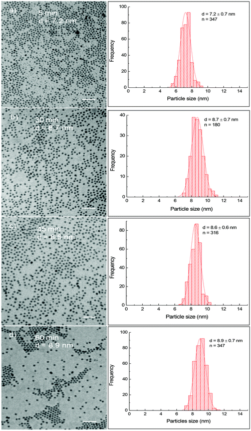
Fig. 1 shows TEM images and their corresponding size distribution histograms of CoFe nanoparticles prepared in the presence of OA/OLA (OA![[thin space (1/6-em)]](https://www.rsc.org/images/entities/char_2009.gif) :
:![[thin space (1/6-em)]](https://www.rsc.org/images/entities/char_2009.gif) OLA = 1
OLA = 1![[thin space (1/6-em)]](https://www.rsc.org/images/entities/char_2009.gif) :
:![[thin space (1/6-em)]](https://www.rsc.org/images/entities/char_2009.gif) 1) at different reaction times. It can be seen that spherical and monodisperse nanoparticles were produced and their size increased slightly from 7.2 ± 0.7 nm to 8.9 ± 0.7 nm as the reaction time increased from 5 min to 60 min. The longer the reaction time, the larger nanoparticles were obtained. In our recent work,20 we have observed a similar relationship between the particle size and the reaction time for cobalt ferrite nanoparticles. In the case of cobalt ferrite nanoparticles, the particle size was readily tuned in a much wider window, from 4.7 nm to over 29.7 nm as the reaction time increased from 5 min to 60 min.20 In the present work, with the same duration of reaction time, the diameter of CoFe nanoparticles can only be varied by 1.5 nm. It is well known that metal carbonyls are thermally unstable. These compounds are rapidly decomposed to release Co and Fe atoms leading to the formation of many small nuclei at the reaction temperature, and thus the Co and Fe sources to feed the growth stage of CoFe nanoparticles were reduced dramatically. As a result, the particle size increased insignificantly with prolonging reaction time. On the contrary, cobalt and iron acetylacetonates are thermally stable. At the initial stage of decomposition, only a portion of the precursors decomposed for the formation of nuclei, more cobalt and iron sources are reserved in the solution for the further growth of the ferrite nanoparticles. Consequently, significantly larger nanoparticles were obtained by extending the reaction time.
1) at different reaction times. It can be seen that spherical and monodisperse nanoparticles were produced and their size increased slightly from 7.2 ± 0.7 nm to 8.9 ± 0.7 nm as the reaction time increased from 5 min to 60 min. The longer the reaction time, the larger nanoparticles were obtained. In our recent work,20 we have observed a similar relationship between the particle size and the reaction time for cobalt ferrite nanoparticles. In the case of cobalt ferrite nanoparticles, the particle size was readily tuned in a much wider window, from 4.7 nm to over 29.7 nm as the reaction time increased from 5 min to 60 min.20 In the present work, with the same duration of reaction time, the diameter of CoFe nanoparticles can only be varied by 1.5 nm. It is well known that metal carbonyls are thermally unstable. These compounds are rapidly decomposed to release Co and Fe atoms leading to the formation of many small nuclei at the reaction temperature, and thus the Co and Fe sources to feed the growth stage of CoFe nanoparticles were reduced dramatically. As a result, the particle size increased insignificantly with prolonging reaction time. On the contrary, cobalt and iron acetylacetonates are thermally stable. At the initial stage of decomposition, only a portion of the precursors decomposed for the formation of nuclei, more cobalt and iron sources are reserved in the solution for the further growth of the ferrite nanoparticles. Consequently, significantly larger nanoparticles were obtained by extending the reaction time.
In the current study, we also investigate the influence of the concentration, ratio and type of surfactants on the particle size. In addition to OA and OLA, we also used trioctylphosphine oxide (TOPO) as a surfactant/co-surfactant for synthesis. Fig. S1† shows TEM images and histograms of the size distribution of CoFe nanoparticles synthesised under different synthetic conditions, including the concentration of reagents or nature of surfactants (Table S1†). It can be seen that monodisperse CoFe nanoparticles with the size in the range of 5–11 nm were obtained by varying the concentration and the type of surfactants (Fig. S1 and Fig. 2).
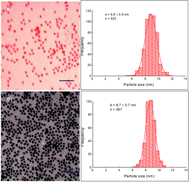 | ||
| Fig. 2 TEM images and their corresponding size distribution histograms of CoFe@Pt nanoparticles synthesised at different reaction times: (a) 45 min and (b) 60 min. Scale bar: 50 nm. | ||
3.2. Platinum coated CoFe nanoparticles
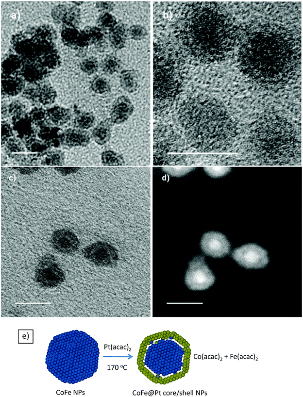
Pt coating was formed by reduction of Pt2+ ions onto the surfaces of CoFe nanoparticles in the presence of a capping agent and in organic solvents. It is well known that cobalt and iron metals can reduce platinum ions into platinum metals via a redox-transmetalation process.21,22 In the current study, the coating was carried out in the presence of OLA and used as a stabilising ligand. OA/OLA capped CoFe nanoparticles prepared at 45 min of reaction time were used as seeds (templates) for the deposition of the Pt shell. Fig. 2 shows TEM images of the Pt coated CoFe nanoparticles synthesised after 45 min and 60 min of reaction. It can be seen that the size of nanoparticles was almost unchanged after the coating (Fig. 1 and 2). The particle sizes of core/shell nanostructures synthesised at the reaction times of 45 and 60 min were almost unchanged (about 8.7 nm), similarly to that of the CoFe nanoparticles.To investigate the core/shell structures, the sample was characterised using HRTEM. The HRTEM images of CoFe@Pt nanoparticles synthesised after 60 min reaction clearly show core/shell structures with a bright and about 2 nm thick shell around a dark core, 4.5 nm (Fig. 3a and b). This feature is opposite to what is expected (i.e. a light shell surrounded a dark core) and is because of the mass contrast dominated over diffraction contrast resulting in the lighter shell even though Pt has a higher electron density than CoFe. Analogous results have recently been observed for Co@Ag,23,24 Ni@Au25 and Fe@Au26 core/shell nanoparticles by several authors. In the current study, it is possible to eliminate the formation of Pt@CoFe core/shell structures with the CoFe shell coating over the Pt core as Pt was reduced after the CoFe cores formed.
To confirm the core/shell structures, the sample was further characterised by utilising STEM and Z contrast images, which are presented in Fig. 3c and d. The images clearly show the core/shell structures. From the dark field image (Fig. 3d), it should be noted that a dark area existing between the bright core and the grey shell indicates the existence of a gap between the CoFe core and the Pt shell. In our study, OLA was used as a reductant to reduce Pt2+ to a Pt metal with the expectation that the size of the magnetic cores would be preserved. It was known that Fe and Co metals can reduce Au3+ and Pt2+ to Au and Pt metals through a process known as redox-transmetalation/galvanic replacement (a metal with more negative redox potential can reduce ions of more positive redox-potential into a metal state).21,22,27 The reduction potential for Pt2+/Pt is +1.2 V, whereas for Co2+/Co and Fe2+/Fe is −0.28 and −0.44 V, respectively. Therefore, the decrease of magnetic core size and formation of the gap between the CoFe core and the Pt shell suggests that redox-transmetalation/galvanic replacement reactions were mainly involved in the reduction of Pt2+ to a Pt metal in the coating process. The possible replacement reactions can be expressed as follows:
| Pt(acac)2 + Fe → Pt + Fe(acac)2 | (2) |
| Pt(acac)2 + Co → Pt + Co(acac)2 | (3) |
Schematic illustration of the formation of CoFe@Pt core/shell nanostructures is presented in Fig. 3e. We also conducted some UV-vis measurements to confirm the formation of the core/shell nanostructures. Fig. S3† shows the UV-vis spectra of the uncoated and CoFe@Pt core/shell nanoparticles. It can be seen that there was no absorption peak in the visible range recorded for both samples. However, we observed a strong surface plasmon resonance (SPR) peak at around 267 nm in the UV-vis spectrum of the core/shell nanoparticles, which is evident for the formation of the platinum shell.28–30 Previously, it was indicated that Au@Pt core/shell nanoparticles exhibited a SPR peak at 222 nm.28 In the current study, CoFe@Pt nanoparticles show a red shift in the SPR peak, from 222 nm for the Au@Pt nanoparticles to 267 nm for the latter. This is possible due to the existence of a gap between the CoFe core and the Pt shell as determined in Fig. 3c and d. For the uncoated CoFe nanoparticles, we obtained a weak and a broad peak in the range from 220 to 450 nm.
3.3. Magnetic properties of nanoparticles
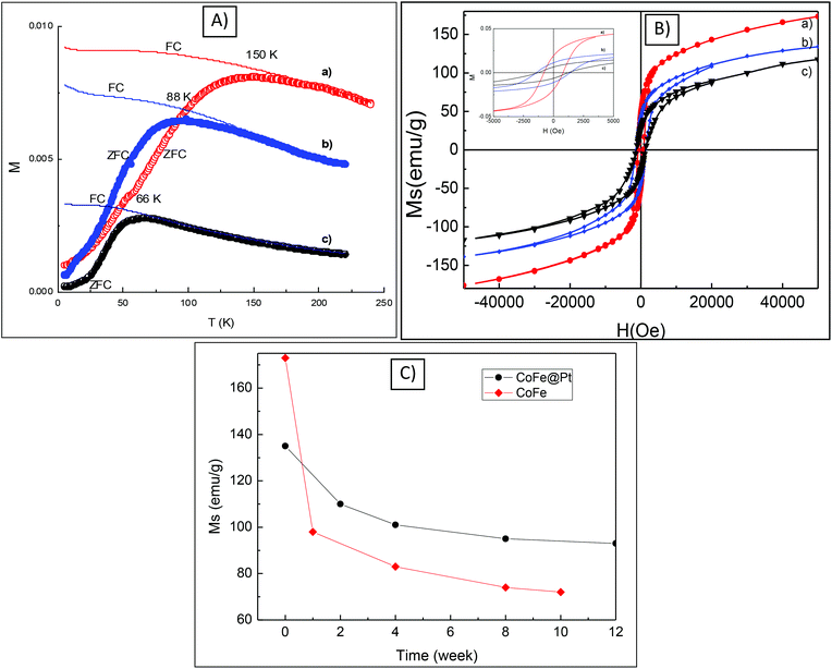
The magnetic properties including blocking temperature (Tb) and coercivity (Hc) of CoFe@Pt core/shell nanoparticles were investigated and compared with those of uncoated CoFe nanoparticles. The ZFC and FC magnetisation curves as a function of the temperature of the CoFe and CoFe@Pt core/shell nanoparticles prepared at different times are shown in Fig. 4. It can be seen that the blocking temperature, Tb (i.e. the temperature at which the nanoparticles become magnetically blocked) of these nanoparticles decreases significantly from 150 K for uncoated CoFe nanoparticles to 66 K for CoFe@Pt core/shell nanoparticles after 60 min reaction. Previously the reduction in the blocking temperature has also been observed in FePt@Au, FePt@SiO2 and Fe3O4@Au core/shell nanoparticles.31–33 In these systems, the size of the magnetic cores was reportedly unchanged after the coating and so the small shift of Tb (i.e. 5 K for Fe3O4@Au, 12 K for FePt@Au and 55 K for FePt@SiO2) was attributed to the reduction of the magnetic dipole–dipole interaction caused by the increasing interparticle spacing of the magnetic cores.34,35 In our study, we observed a much large shift of 84 K for Tb and it is related to the decrease in the size of the magnetic core which is consistent with the observed results of the particle size as shown in HRTEM and STEM images (Fig. 3). We note that the blocking temperature is proportional to volume or 3rd power of dimension of magnetic cores and thus any change in the size of the particle will result in a large shift of Tb as observed for our CoFe@Pt core/shell nanoparticles.Hysteresis loops of the CoFe and CoFe@Pt core/shell nanoparticles were measured at 5 K (Fig. 4b). It can be seen that the nanoparticles have ferromagnetic-like behaviour with open hysteresis loops and the coercivity, Hc, increases from 0.81 kOe for CoFe nanoparticles to 1.41 kOe for CoFe@Pt core/shell nanoparticles synthesised after 45 min of reaction and then it decreases slightly to 1.24 kOe by prolonging the reaction time. The increased coercivity of the core/shell nanoparticles has been previously observed for Co@Ag24 and Fe3O4@ Au.17 This behaviour is generally explained by the enhancement of effective anisotropy due to the increase of surface anisotropy after the coating,36,37 or due to the less-effective coupling of the magnetic dipole moments of the core/shell nanoparticles.18 In addition to this, in our CoFe@Pt core/shell nanoparticles, it is also noted that the size of the magnetic core CoFe decreases compared with uncoated CoFe nanoparticles and it could also result in the decrease of the observed coercivity Hc of the core/shell system as well. The slight decrease in the coercivity with prolonging the reaction time in our CoFe@Pt nanoparticles is similar to that observed by Mandal et al. for Co@Au nanoparticles.38 Using the displacement reaction to coat the Co nanoparticles with the Au shell, the authors reported that the coercivity of Co@Au nanoparticles was constantly decreased with the reaction time with values for Hc being 300, 247 and 91 Oe obtained for 30, 60 and 90 min reaction time, respectively.38
To investigate the chemical stability of CoFe@Pt nanoparticles, the saturation magnetisation Ms was measured at different times after the synthesis. The core/shell nanoparticles (in the powder form) were directly exposed to air, stored, and measured in gel capsules during the study. Fig. 4c shows the change of Ms of the sample with air-exposure time. The value of Ms for the as-synthesized CoFe@Pt NPs (135 emu g−1) was reduced to about 110 emu g−1 after exposure for two week due to oxidation. At longer exposure times, the value of Ms reached a constant value of about 93 emu g−1 after 12 weeks, suggesting that the Pt shell protected effectively the CoFe cores from further oxidation. It should be noted that bare CoFe nanoparticles (OA/OLA capped CoFe nanoparticles) were not chemically stable when exposed to air, the value of Ms dropped from 173 emu g−1 for the as-synthesised CoFe nanoparticles to 95 emu g−1 after exposure for just one week. This value further reduced to reach a stable value of 72 emu g−1 after ten weeks, indicating a total oxidation of the bare CoFe nanoparticles. Accompanied by the reduction of saturation magnetisation Ms, we observed a change in the particles’ morphology of the bare CoFe nanoparticles. As can be seen in Fig. S4,† hollow nanoparticles were observed after one week of synthesis, which is possible due to the Kerkendall effect caused by a rapid oxidation of CoFe nanoparticles when exposed to air.39,40 For the Pt coated CoFe nanoparticles, only solid nanoparticles were observed on the TEM image (Fig. S4†).
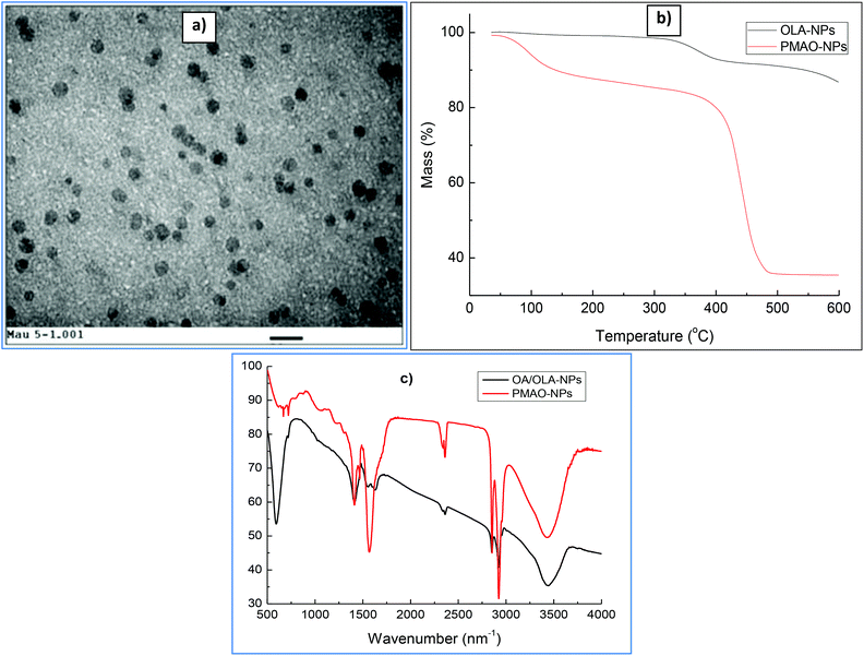
In the current study, CoFe@Pt nanoparticles were made water-dispersible by encapsulating the hydrophobic core/shell nanoparticles with the PMAO ligand. Fig. 5a shows the TEM image of PMAO encapsulated CoFe@Pt nanoparticles. It can be seen that the nanoparticles are well isolated and no aggregates were observed. The presence of PMAO on the particles’ surface was identified by TGA and FTIR measurements. TGA plots were recorded under a nitrogen atmosphere at a constant heating rate of 10 °C min−1 (Fig. 5B). For the sample before encapsulating (OA/OLA coated CoFe@Pt NPs), we observed a weight loss of about 16% in the temperature range of 300–550 °C due to the decomposition of OLA and OA. After modification with PMAO, a large weight loss of 62% was recorded, which is assigned to the evaporation of water adsorbed on the particle surface during the storage of the sample (≈10%) and the decomposition of OA/OLA (≈16%) and PMAO (≈36%). The encapsulation of PMAO on CoFe@Pt nanoparticles was also verified by FTIR measurements. Fig. 5C shows FTIR spectra of OLA/OLA and PMAO capped nanoparticles. The wavenumber ranging from 3300–3500 cm−1 can be assigned to water hydration on the surface of the nanoparticles. The bands at 2810 and 2900 cm−1 indicate the presence of CH2 groups of both OLA/OLA and PMAO capped samples. In the OLA/OA capped sample, the bands appearing in the range of 1550–1630 cm−1 are assigned to the amine group of OLA molecules. The presence of PMAO on the surface of nanoparticles after encapsulating can be confirmed by the existence of a strong band at 1570 cm−1 of ionised carboxylic acid groups due to the opening of anhydride rings. The presence of the carboxylic acid group makes the PMAO capped nanoparticles disperse well in aqueous solution.
3.4. Colloidal stability
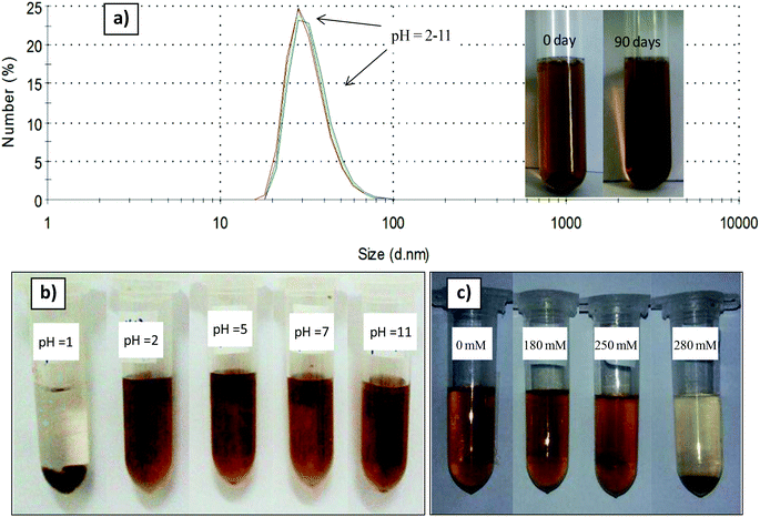
The polymer coated nanoparticles exhibit high colloidal stability in water for at least 3 months, as shown in Fig. 6 (inset) no aggregated or precipitated nanoparticles were observed. PMAO capped nanoparticles are also colloidally stable in a wide range of pH from 2 to 11, as only one peak at round 28 nm on the DLS spectra was observed (Fig. 6a). The nanoparticles are unstable and precipitate at a low pH of 1 (Fig. 6b). As for NaCl concentrations up to 250 mM, the PMAO coated nanoparticles are well dispersed and stable in the solution. When the NaCl concentration increases to 280 mM the nanoparticles are aggregated and precipitated in the solution (Fig. 6c).4. Conclusions
In summary, monodisperse CoFe@Pt core/shell nanoparticles have been successfully prepared in organic solvents. HRTEM and STEM analyses confirmed CoFe@Pt core/shell nanostructures. The results also revealed that the size of CoFe cores decreased significantly after Pt coating indicating that a galvanic replacement/transmetalation process was mainly involved. The Pt shell was effective in protecting the core CoFe from rapid oxidation. The CoFe@Pt core/shell nanoparticles were successfully transferred into water by the encapsulation of hydrophobic OA/OLA capped CoFe@Pt nanoparticles with the amphiphilic PMAO polymer. The PMAO encapsulated CoFe@Pt nanoparticles are well dispersed and are stable in water for at least 3 months and in a wide range of pH from 2 to 11 as well as reasonably high electrolyte concentrations. The method opened a new approach in synthesising high magnetic moment FeCo nanoparticles with a biocompatible coating that will have huge potential in biomedical applications. These Pt coated CoFe core/shell nanoparticles are also possibly promising for the SERS sensing applications.Acknowledgements
The authors are grateful for financial support for this work by the National Foundation for Science and Technology Development (grant 103.02-2012.74 and DT.NCCB-DHUD.2012-G/08). This work was also partly supported by the US-AFOSR/AOARD. Nguyen T. K. Thanh thanks EPSRC for financial support.Notes and references
- H. W. Gu, K. M. Xu, C. J. Xu and B. Xu, Chem. Commun., 2006,(9), 941–949 RSC.
- W. S. Seo, J. Lee, X. M. Sun, Y. Suzuki, D. Mann, Z. Liu, M. Terashima, P. C. Yang, M. V. McConnell, D. G. Nishimura and D. H. Dai, Nat. Mater., 2006, 5(12), 971–976 CrossRef CAS PubMed.
- J. H. Lee, Y. M. Huh, Y. Jun, J. Seo, J. Jang, H. T. Song, S. Kim, E. J. Cho, H. G. Yoon, J. S. Suh and J. Cheon, Nat. Med., 2007, 13(1), 95–99 CrossRef CAS PubMed.
- H. Kosuge, S. P. Sherlock, T. Kitagawa, M. Terashima, J. K. Barral, D. G. Nishimura, H. J. Dai and M. V. McConnell, PLoS One, 2011, 6(1), e14523 CAS.
- J. H. Lee, S. P. Sherlock, M. Terashima, H. Kosuge, Y. Suzuki, A. Goodwin, J. Robinson, W. S. Seo, Z. Liu, R. Luong, M. V. McConnell, D. G. Nishimura and H. J. Dai, Magn. Reson. Med., 2009, 62, 1497–1509 CrossRef PubMed.
- R. Hachani, M. Lowdell, M. Birchall, A. Hervault, D. Merts, S. Begin-Colin and N. T. K. Thanh, Nanoscale, 2016, 8, 3278–3287 RSC.
- R. Hachani, M. Lowdell, M. Birchall and N. T. K. Thanh, Nanoscale, 2013, 5, 11362–11373 RSC.
- X. Meng, H. Seton, L. T. Lu, I. Prior, N. T. K. Thanh and B. Song, Nanoscale, 2011, 3, 977–984 RSC.
- L. M. Parkes, R. Hodgson, L. T. Lu, L. D. Tung, I. Robinson, D. G. Fernig and N. T. K. Thanh, Contrast Media Mol. Imaging, 2008, 3, 150–156 CrossRef CAS PubMed.
- R. Hergt, S. Dutz, R. Muller and M. Zeisberger, J. Phys.: Condens. Matter, 2006, 18(38), S2919–S2934 CrossRef CAS.
- C. Blanco-Andujar, P. Southern, D. Ortega, S. A. Nesbitt, Q. A. Pankhurst and N. T. K. Thanh, Nanoscale, 2015, 7, 1768–1775 RSC.
- C. Blanco-Andujar, P. Southern, D. Ortega, S. A. Nesbitt, Q. A. Pankhurst and N. T. K. Thanh, Nanomedicine, 2016, 11, 121–136 CrossRef CAS PubMed.
- A. Hervault and N. T. K. Thanh, Nanoscale, 2014, 6, 11553–11573 RSC.
- A. Hervault, M. Lim, C. Boyer, A. Dunn, D. Mott, S. Maenosono and N. T. K. Thanh, Nanoscale, 2016, 8, 12152–12161 RSC.
- H. Y. Park, M. J. Schadt, L. Wang, I. I. S. Lim, P. N. Njoki, S. H. Kim, M. Y. Jang, J. Luo and C. J. Zhong, Langmuir, 2007, 23(17), 9050–9056 CrossRef CAS PubMed.
- S. J. Cho, J. C. Idrobo, J. Olamit, K. Liu, N. D. Browning and S. M. Kauzlarich, Chem. Mater., 2005, 17(12), 3181–3186 CrossRef CAS.
- H. Yu, M. Chen, P. M. Rice, S. X. Wang, R. L. White and S. H. Sun, Nano Lett., 2005, 5, 379–382 CrossRef CAS PubMed.
- M. Zubris, R. B. King, H. Garmestani and R. Tannenbaum, J. Mater. Chem., 2005, 15, 1277–1285 CAS.
- J. Z. Wen, C. F. Goldsmith, R. W. Ashcraft and W. H. Green, J. Phys. Chem. C, 2007, 111, 5677–5688 CAS.
- L. T. Lu, N. T. Dung, L. D. Tung, C. T. Thanh, O. K. Quy, N. V. Chuc, S. Maenosono and N. T. K. Thanh, Nanoscale, 2015, 7, 19596–19610 RSC.
- J. I. Park and J. Cheon, J. Am. Chem. Soc., 2001, 123, 5743–5746 CrossRef CAS PubMed.
- W. Lee, M. G. Kim, J. Choi, J. I. Park, S. J. Ko, S. J. Oh and J. Cheon, J. Am. Chem. Soc., 2005, 127, 16090–16097 CrossRef CAS PubMed.
- T. Bala, S. K. Arumugam, R. Pasricha, B. L. V. Prasad and M. Sastry, J. Mater. Chem., 2004, 14(6), 1057–1061 RSC.
- P. Poddar, S. Srinath, J. Gass, B. L. V. Prasad and H. Srikanth, J. Phys. Chem. C, 2007, 111(38), 14060–14066 CAS.
- D. Chen, J. J. Li, C. S. Shi, X. W. Du, N. Q. Zhao, J. Sheng and S. Liu, Chem. Mater., 2007, 19, 3399–3405 CrossRef CAS.
- Z. H. Ban, Y. A. Barnakov, V. O. Golub and C. J. O'Connor, J. Mater. Chem., 2005, 15, 4660–4662 RSC.
- I. Robinson, L. D. Tung, S. Maenosono, C. Walti and N. T. K. Thanh, Nanoscale, 2010, 2, 2624–2630 RSC.
- H. F. Lang, S. Mandonaldo, K. J. Stevenson and B. D. Chendler, J. Am. Chem. Soc., 2004, 126, 12949–12956 CrossRef CAS PubMed.
- M. Khalid, N. Wasio, T. Chase and K. Bandyopadhyay, Nanoscale Res. Lett., 2010, 5, 61–67 CrossRef CAS PubMed.
- J. Zeng, J. Yang, J. Y. Lee and W. Zhou, J. Phys. Chem. B, 2006, 110, 24606–24611 CrossRef CAS PubMed.
- M. Aslam, L. Fu, S. Li and V. P. Dravid, J. Colloid Interface Sci., 2005, 290(2), 444–449 CrossRef CAS PubMed.
- P. De La Presa, M. Multigner, M. P. Morales, T. Rueda, E. Fernandez-Pinel and A. Hernando, J. Magn. Magn. Mater., 2007, 316, E753–E755 CrossRef CAS.
- L. Y. Wang, J. Luo, Q. Fan, M. Suzuki, I. S. Suzuki, M. H. Engelhard, Y. H. Lin, N. Kim, J. Q. Wang and C. J. Zhong, J. Phys. Chem. B, 2005, 109, 21593–21601 CrossRef CAS PubMed.
- J. Garcia-Otero, M. Porto, J. Rivas and A. Bunde, Phys. Rev. Lett., 2000, 84, 167–170 CrossRef CAS PubMed.
- A. K. Boal, B. L. Frankamp, O. Uzun, M. T. Tuominen and V. M. Rotello, Chem. Mater., 2004, 16, 3252–3256 CrossRef CAS.
- H. Zeng and S. H. Sun, Adv. Funct. Mater., 2008, 18, 391–400 CrossRef CAS.
- F. Luis, J. M. Torres, L. M. Garcia, J. Bartolome, J. Stankiewicz, F. Petroff, F. Fettar, J. L. Maurice and A. Vaures, Phys. Rev. B: Condens. Matter, 2002, 65(9), 094409 CrossRef.
- S. Mandal and K. M. Krishnan, J. Mater. Chem., 2007, 17, 372–376 RSC.
- A. Cabot, V. F. Funtes, E. Shevchenko, Y. Yin, L. Balcells, M. A. Markus, S. M. Hughes and P. A. Alivisatos, J. Am. Chem. Soc., 2007, 129, 10358–10360 CrossRef CAS PubMed.
- Y. Yin, R. M. Rioux, C. K. Erdonmez, G. A. Somorjai and A. P. Alivisatos, Science, 2004, 30430, 711–714 CrossRef PubMed.
Footnote |
| † Electronic supplementary information (ESI) available. See DOI: 10.1039/c6nr09325f |
| This journal is © The Royal Society of Chemistry 2017 |

