
Coaxial Ag–base metal nanowire networks with high electrochemical stability for transparent and stretchable asymmetric supercapacitors†
Sangbaek
Park
 ,
Alvin Wei Ming
Tan
,
Jiangxin
Wang
and
Pooi See
Lee
*
,
Alvin Wei Ming
Tan
,
Jiangxin
Wang
and
Pooi See
Lee
*
School of Materials Science and Engineering, Nanyang Technological University Singapore, 50 Nanyang Avenue, Singapore 639798, Singapore. E-mail: pslee@ntu.edu.sg
First published on 19th April 2017
Abstract
Transparent and stretchable Ag–Ni and Ag–Fe core–shell nanowire networks were fabricated as a cathode and anode, respectively, for asymmetric supercapacitors. Both electrodes showed a reversible stretchability at up to 100% strain and exhibited high electrochemical stability and specific capacitances of ∼3 mF cm−2 with 50% optical transmittance. The asymmetric device assembled with a PVA/KOH electrolyte demonstrated a high operating voltage of 1.6 V and an excellent capacitance retention (92%) over 5000 cycles even after stretching to 35% strain.
Conceptual insightsMetal nanowire networks (e.g. Ag NWs) embedded in elastomeric substrates are one of the most promising candidates for stretchable electrodes due to their high electrical conductivity, high optical transparency and compatibility with conventional manufacturing processes by avoiding the use of pre-strained substrates. However, their poor electrochemical stability has limited their application to energy storage devices, which is one of the main challenges. Here, we suggest coaxial Ag–base metal nanowire networks as supercapacitor electrodes which can satisfy all the requirements for such multifunctional power sources. The coaxial core–shell nanowire networks provide synergistic effects by means of (i) high conductivity of Ag nanowires, (ii) electrochemical stability of the metal and its native oxide layer, (iii) high electrochemical activity by the Faradaic reaction of metal oxide, and (iv) mechanical robustness and optical transparency of the nanowire network structure. As a proof of concept, Ag–Ni and Ag–Fe core–shell structures were selected for a cathode and anode, respectively, and assembled into an asymmetric supercapacitor. Interestingly, both electrodes were electrochemically stable, mechanically robust and optically transparent. The assembled device showed a stable electrochemical activity of up to 1.6 V in an aqueous electrolyte and represented the first transparent and stretchable asymmetric supercapacitor. |
A critical need in wearable electronic systems is to find suitable energy storage units that offer similar physical or optical properties as wearable electronics and provide integration capability while maintaining their electrochemical functions under deformation.1 Supercapacitors have been widely studied as possible candidates to meet such requirements with advantages of high power density, long cycling stability, low cost, safe operation and simple configuration.2,3 Pioneering studies based on carbon nanomaterials including carbon nanotubes and graphene have demonstrated various types of supercapacitors: stretchable,4,5 transparent,6,7 stretchable & transparent,8,9 asymmetric stretchable,10,11 and asymmetric transparent12 devices. However, these carbon nanomaterial–based supercapacitors mostly exhibit extrinsic stretchability depending on the strain applied to the substrate before material deposition, which retards integration with other electronics.13
Metal nanowire networks embedded in a polymer matrix are one of the most competitive stretchable electrodes with several advantages, including good mechanical robustness, higher conductivity and transparency compared to carbon nanotubes or graphene.14 Considering that most carbon materials usually need pre-straining of polymer substrates to secure enough stretchability, the intrinsic stretchability of nanowire network structures makes them an ideal fit for integrated systems.15–17 Recently, diverse applications with both stretchable and transparent properties have been reported by using silver nanowires (Ag NWs), e.g. sensors,18 heaters,19 light-emitting diodes,20 and electroluminescent devices.21 In contrast, despite their versatile structural characteristics, Ag NWs have been constrained due to the oxidation issue in their application in electrochemical energy storage devices. Ag atoms on the surface of Ag NWs can be electrochemically oxidized or rapidly dissolved when exposed to an electrolyte containing particular ions (S2−, Cl−, Br−, I−, OH−, H+) in the typical potential range used to charge electrochemical cells.22 In the case of supercapacitors, to date, Ag NWs have only been used as a supporter to provide a one-dimensional nanostructure23–25 or as an auxiliary conductor to deposit other stable conductors26 or tested only at a potential window lower than 0 V vs. NHE.27 Our preliminary work demonstrated stretchable Ag–Zn batteries, where embedding Ag NWs into the polymer matrix allowed only the exposed part of the Ag NWs to be oxidized and the embedded part to maintain its conductivity, although a very thick Ag NW layer was necessary.28 Therefore, despite the attractive potential of Ag NWs as stretchable and transparent metal nanowire networks, enhancing the electrochemical stability of Ag NWs is a fundamental challenge that holds the key to the progress of electrochemical energy storage devices.
Having a protective coating could help to provide a solution to protect Ag NWs against corrosion.29 Several studies have focused on the formation of noble metals (Au, Pt, Pd) or their alloy sheath on Ag NWs through the galvanic replacement reaction.30,31 Recently, Lee et al. reported 5 nm thick-Au coated Ag NWs as a stretchable and transparent electrode and applied them to a symmetric sandwich-type supercapacitor.32 The electrode showed enhanced air stability during 4 weeks after gold coating, but the peak currents of cyclic voltammetry curves were rapidly degraded to 2% of their original value after only 50 cycles with 45 wt% loss of Ag NWs. This indicates that electrochemical oxidation causes the rapid degradation rather than air oxidation. Some have been interested in nickel coatings instead of gold and reported 20 nm-thick Ni coated Cu NWs33 and 55 nm-thick Ni coated Ag NWs34 as air stable and transparent electrodes, although they are not stretchable. Metal oxides (TiO2, Al:ZnO, F:SnO2) on Ag NWs have also been attempted by vacuum deposition and showed high air stability over 2 months, but exhibited poor bending durability due to their brittle natures.35–37 Hence, further breakthroughs are necessary to achieve an ideal nanowire-based electrode with stretchable, transparent and electrochemically stable characteristics.
Here we propose for the first time that coaxial Ag–base metal core–shell nanowire networks could be electrochemically stable in an alkaline aqueous electrolyte over a broad potential range. In this structure, the base metal shell provides a physical barrier, as well as cathodic protection as the oxidation of the Ag NW core is suppressed by sacrificial oxidation (or corrosion), because the base metal shell is more reactive than Ag. Moreover, a native oxide/hydroxide layer formed on the surface of the base metal shell can be fully utilized for surface Faradaic redox reactions, leading to high specific capacitance. To prove this concept, Ag–Ni and Ag–Fe core–shell nanowire networks were fabricated and transferred into a polyurethane acrylate matrix. As a result, both electrodes exhibited highly conductive, stretchable and transparent properties, as well as high electrochemical stability in a KOH electrolyte. Furthermore, a 1.6 V asymmetric full cell supercapacitor, assembled using Ag–Ni NWs as a positive electrode and Ag–Fe NWs as a negative electrode, exhibits an energy density as high as 0.68 mW h cm−3 (superior to reported flexible/stretchable symmetric devices based on transparent carbon nanomaterial electrodes35,36) and high power density (313 mW cm−3) as well as good cycling stability (5000 times with 92% capacitance retention) and stretchability (91% capacitance retention with 35% strain).
In order to obtain highly conductive and electrochemically stable core–shell nanowire networks, we employed a sequential deposition method instead of a conventional approach. The previous methodologies for the coating of a protective layer on Ag NWs are categorized into two types: (i) metal shells are formed on each Ag NWs through a solution process and then the core–shell nanowires are infiltrated with an elastomer;32,33 (ii) Ag NWs are transferred into an elastomeric substrate and then metal shells are coated onto the surface of the Ag NW networks.34 The former case allows all sides of the Ag NW to be covered with a protective layer, but it increases the junction resistance between two core–shell nanowires especially when an easily oxidized metal is used as the shell layer. Conversely, the latter case secures the high conductivity of the Ag NW networks, but the Ag NWs are only partially covered with a protective layer, leading to an exposed Ag region when deforming the substrate (discussed in more detail later). Unlike traditional methods, herein, Ag NWs were deposited and thermally sintered on the glass substrate first, and then the Ag NW networks were directly covered with thin and dense Ni or Fe nanoshells thoroughly by electrodeposition before transferring into a polyurethane acrylate (PUA) polymer matrix (see the Experimental section for details, ESI†). It allows the resultant conductive and stretchable Ag NW networks to be bodily encapsulated in the metal nanoshells, which is advantageous for the protection of the Ag NWs from corrosion.
Fig. 1a shows typical examples of the Ag NWs, Ag–Ni NWs and Ag–Fe NWs embedded in PUA substrates; the electrodes are optically transparent (%T at 550 nm = 78.7%, 54% and 51.2%, respectively; Fig. S1, ESI†) with high conductivity (sheet resistance: 3.1, 1.2 and 2.9 Ω sq−1, respectively). The color change from yellow (Ag) to gray (Ni) or dark blue (Fe) is attributed to the change in absorption properties due to the shell layer coating. Top-view scanning electron microscopy (SEM) images of the electrodes showed that the Ag NWs are thoroughly covered with 20 nm-thick Ni and Fe nanoshells and those core–shell nanowires are inlaid into the surface layer of the PUA polymer (Fig. 1b). It is noted that the percolation network of Ag NWs is well-preserved even after Ni and Fe coating, which is the key to maintaining the high transmission value by retaining a substantial unblocked area in the whole electrode. To confirm the crystal structure of the core–shell nanowires, X-ray diffraction (XRD) was carried out (Fig. 1c). Ag–Ni NW and Ag–Fe NW electrodes display standard diffraction peaks that are well indexed to Ag metal (JCPDS card No. 04-0783), and diffraction peaks indicative of Ni metal (JCPDS card No. 04-0850) and Fe metal (JCPDS card No. 06-0696) are also found. Energy dispersive spectroscopy (EDS) elemental mapping of the Ag–Ni NWs exhibits that the Ni element is uniformly distributed throughout the nanowires while the Ag element has a narrower distribution at the core region of the nanowires (Fig. 1d). Also, the line-scan profile of Ni presents a double-hump pattern with a relatively low content in the center, while that of Ag exhibits one broad peak in the central region (Fig. S2, ESI†), which illustrates the core–shell structure. Interestingly, O element is also detected all over the nanowire, implying that a native oxide layer was successfully formed on the surface of the Ni nanoshells during post-annealing of the Ag–Ni NWs.
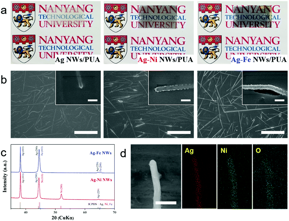 | ||
| Fig. 1 Visual transparency, surface, crystal structure and elemental analysis of Ag NWs and Ag–metal NW electrodes. (a) Photographs and (b) SEM images of Ag NWs (left), Ag–Ni NWs (middle) and Ag–Fe NWs (right) embedded in PUA substrates. Scale bar: 10 μm (inset: 500 nm). (c) XRD graphs of Ag–Ni NWs and Ag–Fe NWs. (d) EDS elemental mapping of a Ag–Ni NW, indicating nickel oxides on the surface. | ||
To test the stretchability, the electrical resistance changes of the Ag NW and Ag–Ni NW electrodes were measured with increasing strain up to 100% (Fig. 2a and its inset). The resistance of the bare Ag NWs increases steadily at relatively small strains and rises steeply after increasing the strain up to 70%, which is in agreement with the previously reported work.20 The relative changes in resistance of the Ag–Ni NWs show a similar tendency, but the resistance increment is much smaller than that of the Ag NWs. The enhanced stretchability is attributed to the reinforced connection between each nanowire by Ni deposition. As mentioned above, the sheet resistance of the Ag NWs was dramatically decreased from 3.1 to 1.2 Ω sq−1 after Ni coating. This means that Ni nanoshells improve the junction conductance between the nanowires, leading to an overall electrode conductivity improvement.31 Also, the resistance changes of the Ag–Ni NWs are well-matched with the ideal resistance curve, R/R0 = (1 + strain)2, implying that there is no loss of nanowire interconnections up to 70% strain.40 This reveals that tightly covered Ni nanoshells contribute to preventing the break-up of the Ag NW networks during stretching.
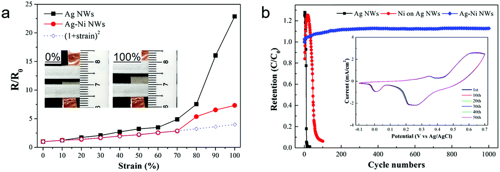 | ||
| Fig. 2 Stretchability and electrochemical stability characterization of electrodes. (a) The relative changes in resistance of Ag NWs and Ag–Ni NWs embedded in PUA substrates under progressively increasing strains. The inset shows photographs of a Ag–Ni NWs/PUA electrode at 0% and 100% strain. (b) Percentage capacitance retention in 1 M aqueous KOH electrolyte of Ag–Ni NW/PUA in comparison with those of Ag NW/PUA and Ni coated Ag NW/PUA. The as-measured CV curves of Ag–Ni NWs along with the number of cycles are presented in the inset (the CV curves of Ag NW/PUA and Ni coated Ag NW/PUA are presented in Fig. S2, ESI†). | ||
The electrochemical stability of Ag–Ni NWs/PUA was evaluated in comparison with both the conventional Ag NWs/PUA and Ni coated on Ag NWs/PUA (used as a control sample). A three-electrode system was used with Pt counter and Ag/AgCl reference electrodes in KOH aqueous electrolyte. Fig. 2b shows the percentage capacitance retention of three electrodes calculated from cyclic voltammetry (CV) curves. Remarkably, the Ag–Ni NWs exhibit better electrochemical stability than other electrodes and gave a 112% capacitance retention after 1000 cycles. There is no significant change in the CV curve of the Ag–Ni NWs, whereas rapid current drops are observed in the CV curves of other electrodes within the initial 50 cycles (inset of Fig. 2b and Fig. S3, ESI†). The outstanding electrochemical stability is attributed to the unique coaxial Ag–Ni nanowire networks which provide (i) an impermeable Ni barrier covering the Ag NW networks thoroughly and (ii) galvanic protection that means the Ag NWs are cathodically protected by the sacrificial corrosion of nickel. In the case of Ni coated on Ag NWs/polymer prepared by the previous method, only the exposed area from the polymer matrix can be covered using Ni shells because electrodeposition of Ni was conducted after transfer of the Ag NWs into the polymer.34 While the Ni redox reaction is the main reaction in our Ag–Ni NWs, the control samples (the Ni coated Ag NWs/polymer after transfer) are plagued by the Ag redox reaction (Fig. S2, ESI†), inducing the oxidation of the Ag core-nanowire and the loss of conductivity. Although electrochemical stability can be enhanced by increasing the thickness of the Ni coating on the control sample, the Ag redox reaction was present even in the 550 nm-thick Ni coated Ag NWs/PUA (from the CV curves); accordingly, it losts 94% of its original capacitance during 100 cycles (Fig. S4, ESI†). This signifies that an impermeable barrier that covers the Ag NWs thoroughly is important to protect the Ag NWs from corrosion. Meanwhile, in the case of the previously reported Au coated Ag NWs, although each Ag NW was densely covered with an Au layer through the solution method, the peak current in the CV curves rapidly dropped to 2%.32 The authors interpreted that the core Ag NWs are partially exposed to electrolyte due to defects or pores in the Au surface. As Au is more stable than Ag, such an exposed region cannot be protected at all. This means that galvanic protection plays an important role in enhancing the electrochemical stability of the Ag–Ni NWs.
The electrochemical properties of the Ag–Ni and Ag–Fe NW electrodes were systematically studied. Fig. 3a and b show the CV curves of the Ag–Ni and Ag–Fe NW electrodes at different scan rates from 10 mV s−1 to 500 mV s−1, respectively. The peak current of the CV curves increases linearly with the square root of the scan rate for both the Ag–Ni and Ag–Fe NW electrodes (Fig. S5, ESI†), indicating that the surface Faradaic reactions are diffusion-controlled and thus the charge-transfer reactions at the electrode/electrolyte interface are relatively fast.38 The Ag–Ni NW electrode exhibits two pairs of redox peaks in the CV curve at 5 mV s−1, where the sharp and intense peaks at 0.38 and 0.31 V are related to the redox reactions of Ni(II) ↔ Ni(III)42 and the broad and small peaks at 0.24 and 0.12 V are related to the redox reactions of Ag(0) ↔ Ag(I)43 as follows:
| NiO + OH− ↔ NiOOH + H2O + e− |
| 2Ag + 2OH− ↔ Ag2O + H2O + 2e− |
 | ||
| Fig. 3 Electrochemical characterization of Ag–metal NWs embedded in PUA. CV curves of (a) a Ag–Ni NW electrode and (b) a Ag–Fe NW electrode as a cathode and an anode for a supercapacitor, respectively, at various scan rates from 10 mV s−1 to 500 mV s−1 in a 1 M KOH electrolyte with a three-electrode system. (c) Specific capacitance of the Ag–Ni and Ag–Fe NW electrode as a function of the scan rate. (d) The Nyquist plots of Ag–Ni and Ag–Fe NW electrodes under the same conditions. The inset shows the high frequency region. | ||
To evaluate Ag–base metal NW electrodes for device applications, the Ag–Ni NWs and Ag–Fe NWs were sandwiched around a PVA/KOH gel electrolyte to assemble an asymmetric supercapacitor as illustrated in Fig. 4a. The potential windows of both electrodes at the same scan rate show that the maximum operation potential of the device can reach up to 1.7 V. As shown in Fig. 4c, the CV curves of the Ag–Ni NW/Ag–Fe NW device exhibit redox humps, attributed to the contribution of the Faradaic reactions of the electrodes. The CV curve is well-maintained even at high scan rates up to 500 mV s−1, suggesting a good rate capability of the asymmetric cell. The specific capacitance value of the device obtained at 500 mV s−1 is 1.2 mF cm−2, retaining 41% of the initial value (2.9 mF cm−2) at a scan rate of 10 mV s−1 (Fig. 4d). Moreover, the asymmetric cell shows good stretchability and the capacitance could be maintained at 91% with increasing the strain up to 35% (Fig. 4e and Fig. S8, ESI†). The slightly increased capacitances by 3.5% and 1.6% when stretched to 5% and 10%, respectively, are attributed to the improved contact between the electrode/electrolyte interface by the shearing force during stretching.46 Furthermore, even after stretching to 35% strain, 92% of the initial capacitance is retained for 5000 cycles, demonstrating a good long-term stability of the device (Fig. 4f). The sharp decrease in the initial 200 cycles is related to the irreversible Fe/Fe(II) reaction47 and gradually increases with increasing cycles likely due to an activation process.48 These results demonstrate the pioneering concept of the stretchable asymmetric supercapacitor based on transparent Ag NW electrodes for the first time.
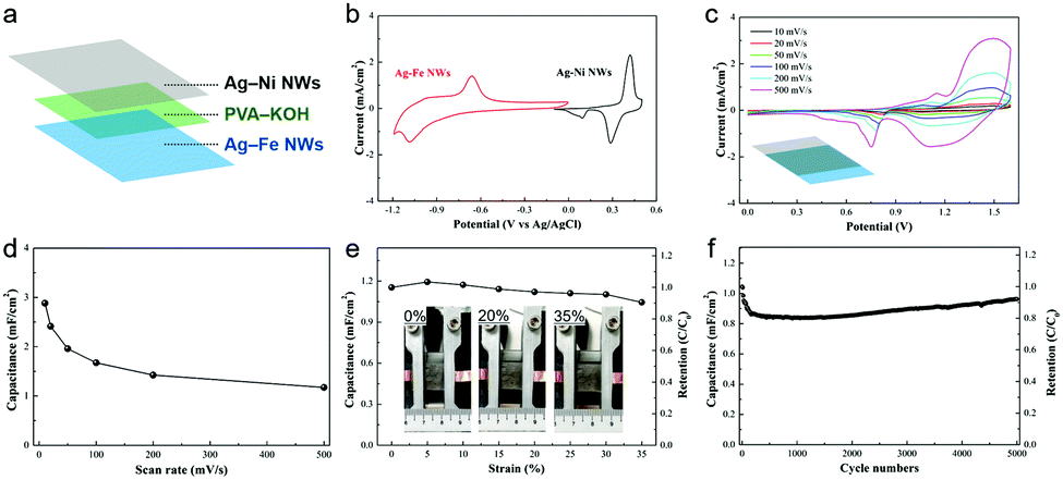 | ||
| Fig. 4 Device characterization of an asymmetric supercapacitor. (a) Scheme for the fabrication of a sandwich-type supercapacitor based on Ag–Ni and Ag–Fe NWs with PVA–KOH gel electrolyte. (b) Comparison of CV curves of Ag–Ni NWs and Ag–Fe NWs at a scan rate of 100 mV s−1 in 1 M KOH aqueous solution. (c) CV curves of the device at various scan rates in the PVA–KOH gel electrolyte. (d) Specific capacitance of the device as a function of the scan rate. (e) Change of the specific capacitance of the device with increasing strain. The inset shows photographs of the device at various strains. (f) Cycling performance of the device after stretching to 35% strain. | ||
To emphasize the versatile application potential of the Ag–base metal NW electrodes, a micro-patterned (MP) device was designed as a prototype for a transparent and stretchable asymmetric supercapacitor (Fig. 5a). The logos behind the device could be seen clearly, exhibiting the transparent feature of the device (Fig. 5b). The CV response of the MP device in the potential range of 0–1.6 V exhibits a broader redox peak in comparison with that of the sandwich-type (Fig. 4c and 5c) because the capacitances of the positive (Ag–Ni NWs) and negative (Ag–Fe NWs) electrodes were modulated to balance the charges. Galvanostatic charge/discharge curves of the transparent MP device were obtained at various current densities in the range from 0.05 to 0.5 mA cm−2 (Fig. 5d). Potential plateaus were observed in the charge and discharge curves, confirming the contribution of the Faradaic reaction, which is in good agreement with the CV tests. The MP device exhibits a specific capacitance of 1.48 mF cm−2 at 0.05 mA cm−2 and a high capacitance retention rate of 45% up to 0.5 mA cm−2 (Fig. 5e). This capacitance value is almost half that in the sandwich-type device, because each MP electrode only covers 50% of the total area in the MP device. The MP device also exhibits good stretchability, where the original capacitance could be maintained up to 20% strain (Fig. S9, ESI†). Additionally, two devices that were connected in series successfully lit up an LED while maintaining their transparent nature (Fig. S10, ESI†). To our best knowledge, this is the first demonstration of a transparent and stretchable asymmetric supercapacitor. The sandwich-type and micro-patterned asymmetric supercapacitors can deliver a maximum energy density of 0.68 and 0.35 mW h cm−3 and still maintain 0.28 and 0.16 mW h cm−3 at a high power density of 313 and 267 mW cm−3, respectively (Fig. 5f). These values are much higher than those of the transparent symmetric supercapacitors based on nanoengineered carbon films38 or microstructured graphene membranes.39
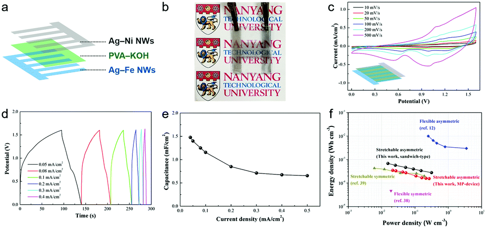 | ||
| Fig. 5 Device characterization of a micro-patterned supercapacitor. (a) Schematic illustration for the fabrication of a micro-patterned (MP) supercapacitor based on Ag–Ni and Ag–Fe NWs with a PVA–KOH gel electrolyte. (b) Photograph of the transparent MP supercapacitor, of which transparency is demonstrated by the visibility of the logo below. (c) CV curves of the MP device at various scan rates. (d) Galvanostatic charging–discharging curves of the MP device at various current densities. (e) Specific capacitance of the MP device as a function of current density. (f) The Ragone plot of the sandwich-type and micro-patterned asymmetric supercapacitors. The volumetric energy and power density of the devices are compared with those of other flexible or stretchable transparent supercapacitors.12,38,39 | ||
Conclusions
In summary, Ag–Ni and Ag–Fe core–shell nanowire networks embedded in polyurethane acrylate polymer substrates have been successfully fabricated as a new family of transparent and stretchable conducting electrodes for supercapacitors through a facile electrodeposition and transfer method. The unique structure where the welded Ag nanowire network is thoroughly covered with Ni or Fe nanoshells guarantees high electrochemical stability of the electrodes in KOH electrolyte over the typical operating potential window, as well as providing high specific capacitances (∼3 mF cm−2 with 50% optical transmittance) due to the surface Faradaic reactions of metal oxide/hydroxide layers. The Ag–Ni NWs(+)//Ag–Fe NWs(−) asymmetric supercapacitor operated at 1.6 V delivers high energy density (0.68 mW h cm−3), high power density (313 mW cm−3), and excellent cycling stability (5000 cycles, 92% retention) with good stretchability (35% strain, 91% retention). Furthermore, a transparent and stretchable asymmetric supercapacitor is demonstrated for the first time by combining the micro-patterned Ag–base metal NW electrodes. This work offers a possible route toward electrochemically durable metal nanowire transparent conductors, which are versatile for developing advanced electrochemical devices in integrated wearable electronic systems.Acknowledgements
This research is funded by the NRF Competitive Research Programme NRF-CRP13-2014-02, which is supported by the National Research Foundation, Prime Minister's Office, Singapore. The authors thank G. Cai for the EDS line measurements.Notes and references
- W. Liu, M. S. Song, B. Kong and Y. Cui, Adv. Mater., 2017, 29, 1–34 Search PubMed
.
- B. C. Kim, J.-Y. Hong, G. G. Wallace and H. S. Park, Adv. Energy Mater., 2015, 5, 1500959 CrossRef
- W. Du, R. Liu, Y. Jiang, Q. Lu, Y. Fan and F. Gao, J. Power Sources, 2013, 227, 101–105 CrossRef CAS
- C. Yu, C. Masarapu, J. Rong, B. Wei and H. Jiang, Adv. Mater., 2009, 21, 4793–4797 CrossRef CAS PubMed
- J. Zang, C. Cao, Y. Feng, J. Liu and X. Zhao, Sci. Rep., 2014, 4, 6492 CrossRef CAS PubMed
- K. Lee, H. Lee, Y. Shin, Y. Yoon, D. Kim and H. Lee, Nano Energy, 2016, 26, 746–754 CrossRef CAS
- P. Kanninen, N. D. Luong, H. Sinh le, I. V. Anoshkin, A. Tsapenko, J. Seppala, A. G. Nasibulin and T. Kallio, Nanotechnology, 2016, 27, 235403 CrossRef PubMed
- T. Chen, H. Peng, M. Durstock and L. Dai, Sci. Rep., 2014, 4, 3612 CrossRef PubMed
- P. Xu, J. Kang, J.-B. Choi, J. Suhr, J. Yu, F. Li, J.-H. Byun, B.-S. Kim and T.-W. Chou, ACS Nano, 2014, 8, 9437–9445 CrossRef CAS PubMed
- Q. Tang, M. Chen, C. Yang, W. Wang, H. Bao and G. Wang, ACS Appl. Mater. Interfaces, 2015, 7, 15303–15313 CAS
- Q. Tang, W. Wang and G. Wang, ACS Appl. Mater. Interfaces, 2016, 8, 27701–27709 CAS
- N. Li, C. Zhi and H. Zhang, Electrochim. Acta, 2016, 220, 618–627 CrossRef CAS
- J. Pu, X. Wang, R. Xu and K. Komvopoulos, ACS Nano, 2016, 10, 9306–9315 CrossRef CAS PubMed
- T. Sannicolo, M. Lagrange, A. Cabos, C. Celle, J. P. Simonato and D. Bellet, Small, 2016, 12, 6052–6075 CrossRef CAS PubMed
- C. Yan, J. Wang, X. Wang, W. Kang, M. Cui, C. Y. Foo and P. S. Lee, Adv. Mater., 2014, 26, 943–950 CrossRef CAS PubMed
- Z. Luo, Y. Jiang, B. D. Myers, D. Isheim, J. Wu, J. F. Zimmerman, Z. Wang, Q. Li, Y. Wang, X. Chen, V. P. Dravid, D. N. Seidman and B. Tian, Science, 2015, 348, 1451–1455 CrossRef CAS PubMed
- B. Tian, P. Xie, T. J. Kempa, D. C. Bell and C. M. Lieber, Nat. Nanotechnol., 2009, 4, 824–829 CrossRef CAS PubMed
- W. Hu, X. Niu, R. Zhao and Q. Pei, Appl. Phys. Lett., 2013, 102, 083303 CrossRef
- S. Hong, H. Lee, J. Lee, J. Kwon, S. Han, Y. D. Suh, H. Cho, J. Shin, J. Yeo and S. H. Ko, Adv. Mater., 2015, 27, 4744–4751 CrossRef CAS PubMed
- J. Liang, L. Li, X. Niu, Z. Yu and Q. Pei, Nat. Photonics, 2013, 7, 817–824 CrossRef CAS
- J. Wang, C. Yan, K. J. Chee and P. S. Lee, Adv. Mater., 2015, 27, 2876–2882 CrossRef CAS PubMed
- M. Giovanni and M. Pumera, Electroanalysis, 2012, 24, 615–617 CrossRef CAS
- W. Liu, C. Lu, X. Wang, R. Y. Tay and B. K. Tay, ACS Nano, 2015, 9, 1528–1542 CrossRef CAS PubMed
- S. Wu, K. S. Hui and K. N. Hui, J. Phys. Chem. C, 2015, 119, 23358–23365 CAS
- Z. Qiao, X. Yang, S. Yang, L. Zhang and B. Cao, Chem. Commun., 2016, 52, 7998–8001 RSC
- Z. Yu, C. Li, D. Abbitt and J. Thomas, J. Mater. Chem. A, 2014, 2, 10923–10929 CAS
- R. Yuksel, S. Coskun and H. E. Unalan, Electrochim. Acta, 2016, 193, 39–44 CrossRef CAS
- C. Yan, X. Wang, M. Cui, J. Wang, W. Kang, C. Y. Foo and P. S. Lee, Adv. Energy Mater., 2014, 4, 1301396 CrossRef
- S. Ye, A. R. Rathmell, Z. Chen, I. E. Stewart and B. J. Wiley, Adv. Mater., 2014, 26, 6670–6687 CrossRef CAS PubMed
- Y. Sun, Z. Tao, J. Chen, T. Herricks and Y. Xia, J. Am. Chem. Soc., 2004, 126, 5940–5941 CrossRef CAS PubMed
- L. Hu, H. S. Kim, J.-Y. Lee, P. Peumans and Y. Cui, ACS Nano, 2010, 4, 2955–2963 CrossRef CAS PubMed
- H. Lee, S. Hong, J. Lee, Y. D. Suh, J. Kwon, H. Moon, H. Kim, J. Yeo and S. H. Ko, ACS Appl. Mater. Interfaces, 2016, 8, 15449–15458 CAS
- A. R. Rathmell, M. Nguyen, M. Chi and B. J. Wiley, Nano Lett., 2012, 12, 3193–3199 CrossRef CAS PubMed
- H. Eom, J. Lee, A. Pichitpajongkit, M. Amjadi, J. H. Jeong, E. Lee, J. Y. Lee and I. Park, Small, 2014, 10, 4171–4181 CAS
- D. G. Lee, D. Lee, J. S. Yoo, S. Lee and H. S. Jung, Nano Convergence, 2016, 3, 20 CrossRef PubMed
- X. Yan, J. Ma, H. Xu, C. Wang and Y. Liu, J. Phys. D: Appl. Phys., 2016, 49, 325103 CrossRef
- A. Y. Kim, M. K. Kim, C. Hudaya, J. H. Park, D. Byun, J. C. Lim and J. K. Lee, Nanoscale, 2016, 8, 3307–3313 RSC
- H. Y. Jung, M. B. Karimi, M. G. Hahm, P. M. Ajayan and Y. J. Jung, Sci. Rep., 2012, 2, 773 Search PubMed
- N. Li, G. Yang, Y. Sun, H. Song, H. Cui, G. Yang and C. Wang, Nano Lett., 2015, 15, 3195–3203 CrossRef CAS PubMed
- W. Hu, X. Niu, L. Li, S. Yun, Z. Yu and Q. Pei, Nanotechnology, 2012, 23, 344002 CrossRef PubMed
- T. W. Lin, C. S. Dai and K. C. Hung, Sci. Rep., 2014, 4, 7274 CrossRef CAS PubMed
- M. Jamal, M. Hasan, M. Schmidt, N. Petkov, A. Mathewson and K. M. Razeeb, J. Electrochem. Soc., 2013, 160, B207–B212 CrossRef CAS
- Y.-J. Song, J. Chen, J.-Y. Wu and T. Zhang, J. Nanomater., 2014, 2014, 1–7 Search PubMed
- S. Gong, Y. Zhao, Q. Shi, Y. Wang, L. W. Yap and W. Cheng, Electroanalysis, 2016, 28, 1298–1304 CrossRef CAS
- L. Basirico and G. Lanzara, Nanotechnology, 2012, 23, 305401 CrossRef CAS PubMed
- X. Chen, H. Lin, P. Chen, G. Guan, J. Deng and H. Peng, Adv. Mater., 2014, 26, 4444–4449 CrossRef CAS PubMed
- C.-Y. Kao and K.-S. Chou, J. Power Sources, 2010, 195, 2399–2404 CrossRef CAS
- C. Zhou, Y. Zhang, Y. Li and J. Liu, Nano Lett., 2013, 13, 2078–2085 CrossRef CAS PubMed
Footnote |
| † Electronic supplementary information (ESI) available: Transmission spectra, SEM, EDS line-scanning, CV, stability test, stretchability test, demonstration and experimental details. See DOI: 10.1039/c7nh00024c |
| This journal is © The Royal Society of Chemistry 2017 |