DOI:
10.1039/C7GC00497D
(Paper)
Green Chem., 2017,
19, 1911-1918
Blue light mediated C–H arylation of heteroarenes using TiO2 as an immobilized photocatalyst in a continuous-flow microreactor†
Received
15th February 2017
, Accepted 16th March 2017
First published on 30th March 2017
Abstract
Titanium dioxide was applied as an immobilized photocatalyst in a microstructured falling film reactor for the continuous-flow C–H arylation of heteroarenes with aryldiazonium salts as the starting material. Detailed investigations of the catalyst and a successful long-term run proved its excellent usability for this process. Very good yields up to 99% were achieved with broad substrate scope and were compared with batch synthesis. The transfer to the continuous-flow mode revealed an impressive boost in reactor performance solely resulting from the improved irradiation and contact of the catalyst, substrate and light.
Introduction
Titanium dioxide has proved its potential as a heterogeneous photocatalyst for various applications in chemical synthesis.1 The outstanding chemical and photochemical stabilities of TiO2 allow, in combination with its high availability, low cost and non-toxicity, its use in advanced oxidation processes (AOP) for the mineralization of toxic compounds in wastewater.2 In contrast to degradation processes TiO2 has also attracted considerable interest as a photocatalyst for fine chemical syntheses.3 Alcohol,4 amine5 and thiol6 oxidation to aldehydes, imines and disulfides, respectively, are known as well as various methods for C–C7 and C–heteroatom8,9 bond forming reactions. Hydrogenation reactions, of e.g. nitro arenes to the respective amines,10 or the cyclisation of L-lysine to L-pipecolinic acid,11 have been performed with pure TiO2 or with Pt nanoparticles as a co-catalyst attached to the TiO2 particle surface. Particularly the use of co-catalysts with TiO2 has been explored in recent times in order to overcome the limiting UV absorption range of pure TiO2 and enter the visible light region for a milder and even more sustainable synthetic photo-process.12–15 The in situ surface modification of TiO2 is another possibility to enhance the absorption range of the photocatalyst. As recently shown by Rueping et al., the TiO2 surface catalysed formation of a TiO2 azoether from aromatic diazonium salts results in a strong light absorption in the blue region with a maximum of approx. 450 nm.16 Irradiating this substrate–catalyst combination results in the formation of aryl radicals, which efficiently add to heteroarenes like furan or thiophene available in the reaction solution.
In parallel to the development of photochemically catalysed reactions with visible light, continuous-flow technology has become one important tool for photochemists.17–19 Micro-tubular-based reactors are a commonly used reactor type for photochemical transformations.20–22 They are equipped with thin light transparent capillaries having an inner diameter of less than a millimetre. Energy-efficient light emitting diodes are recommended for the wavelength-selective irradiation of the liquid thin film of the reaction solution inside the capillary.23,24 In contrast to batch photo-reactions continuous-flow reactors allow the exact control of the irradiation time by the flow rate of the reaction solution being pumped through the capillary. This advantage minimizes detrimental effects on the product formation due to over-irradiation. Besides these advantages microstructured reactors also allow an intense mixing of liquid or gas–liquid phases inside the micro-sized channels yielding efficient mass transfer and accelerated reactions.25–28 The use of solid phases like heterogeneous photocatalysts needs another reactor design. Flexible capillaries are replaced by stiff microchannels made of inert polymers or glass. A heterogeneous catalyst material can be then coated to the walls of the microchannels.29 This approach is usually used for reaction screening and synthesis development in chip reactors with a small internal volume and low flow rate on the μL min−1 scale.30–32
For scale-up of a well-explored batch photo-reaction and its transfer into continuous-flow mode a larger reactor type is necessary, like the microstructured falling film reactor (FFMR) (Fig. 1). The design and working principle of the FFMR allows the formation of liquid thin films in open stainless steel microchannels with a thin film thickness below 100 μm and flow rates of 1 mL min−1 for the standard reactor version and up to 10 mL min−1 for the large reactor version (for more details, see the ESI†).33–36 The FFMR has already been used for photochemical reactions like photochlorinations37 and dye-sensitized singlet oxygen formation.38,39 Very recently the FFMR was evaluated in detail for the dye-sensitized photooxygenation of 1,5-dihydroxynaphthalene to Juglone.40
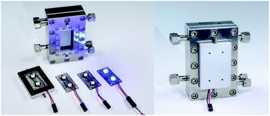 |
| | Fig. 1 FFMR as the key element of the lab plant with a royal blue LED array in a heat sink magnetically fixed to the top plate of the microreactor (© Fraunhofer ICT-IMM). | |
In the work presented here the FFMR technology is used for the first time with a heterogeneous photocatalyst immobilized inside the microchannels. Based on previous work by Rueping et al. on the TiO2 catalyzed C–H arylation of heteroarenes with diazonium salts as the starting material, this reaction is transferred from small scale batch to continuous-flow mode in the FFMR with TiO2 as an immobilized photocatalyst in stainless steel microchannels. Besides catalyst analysis a wide range of aryldiazonium salts are investigated with furan, thiophene and pyridine as heteroarenes including a long-term run. Calculation of the specific reactor performance proves a considerable boost in the performance and superiority of continuous-flow synthesis in the FFMR against batch synthesis.
Results and discussion
Catalyst immobilisation and analysis
For all experiments reaction plates were used with 32 microchannels and a channel architecture of 600 μm in width, 200 μm in depth and 78 mm in length (Fig. 2, left). TiO2 (24 mg, anatase modification) was immobilized as a catalytically active metal oxide as described in the Experimental section (vide infra). Cleaning of the reaction plate with citric acid and heat treatment at 800 °C prior to the immobilization of the metal oxide with poly-vinyl alcohol as a binder enables strong adhesion of the catalyst material to the stainless steel surface.41 The applied method allows the immobilisation of a thin TiO2 layer solely in the microchannels of the reaction plate. The surface roughness of the calcined catalyst material was investigated for five measuring lengths of 4 mm along the bottom of one microchannel. The arithmetical mean deviation of the roughness profile is Ra = 1.84 μm, and the average surface roughness is Rz = 13.71 μm (Fig. 2, right and ESI†). The data from these experiments indicate a constant roughness with an equal distribution of catalyst material on the wall of the surveyed microchannel. The surface roughness allows the generation of turbulence in the liquid thin film for efficient contact of the liquid stream with the catalyst surface.
 |
| | Fig. 2 FFMR reaction plate with TiO2 immobilized in 32 microchannels (left) and the roughness of the catalyst material inside a microchannel (right). | |
The specific surface area and the pore diameter of the catalyst material were analysed before and after calcination (see the ESI† for details). Prior to the thermal treatment TiO2 powder had a specific surface area of 157.11 m2 g−1 with a median pore diameter of 6.6 nm. After wet catalyst preparation and calcination at 450 °C the specific surface area was reduced to 118.93 m2 g−1, whereas the median pore diameter had increased to 8.7 nm. These values obtained with the BET and BJH methods show a typical trend of mesoporous TiO2 upon thermal treatment.42 Transmission electron microscopy (TEM) was used to visualize the particle size of TiO2 before and after calcination. Large agglomerates are observed in both cases. Before temperature treatment TiO2 particles show a regular dimension within the larger agglomerates (Fig. 3, left). After thermal treatment TiO2 particles tend to stick together to larger structures within the agglomerates (Fig. 3, right). This appearance can be attributed to the adhesion between the particles upon interaction with the binder from catalyst preparation.
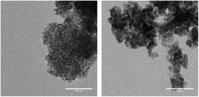 |
| | Fig. 3 TEM images of TiO2 particles before (left) and after (right) calcination at 450 °C (length scale: 100 nm). | |
Further analysis of TiO2 was carried out using X-ray diffraction (XRD) in order to gain insight into the crystal modification of nano-powderous TiO2 before and after thermal treatment. All patterns exhibit reflections due to the anatase as well as the rutile modification of TiO2, the latter being the minor component (Fig. 4). The reflection profiles of the anatase phase are broad as expected for nanoscale materials, yet the tips of the reflections are too sharp. Thus the anatase component was modelled using two phases of identical crystallographic data, but with different crystallite sizes and mass ratios. In this model the sharp tips of the reflection profiles are due to a minor component of approx. 5 wt% with a crystallite size larger than 100 nm. In this crystallite size regime reflection broadening due to the crystallite size and the broadening due to the diffractometer technical limits become comparable, thus a more precise value of the crystallite size of the minor phase cannot be determined from laboratory diffractometer data. Importantly, calcination changes the TiO2 catalyst only negligibly, but the composition and crystallite size before and after calcination are virtually the same.
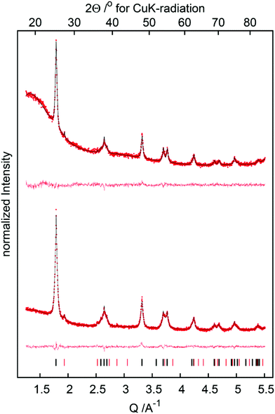 |
| | Fig. 4 X-ray powder diffraction patterns of the TiO2 before (bottom) and after (top) calcination (red dots: experimental data, black line: fit, red line: difference curve; ticks indicate the reflection positions of the anatase (black) and rutile (red) phases, respectively). | |
Scanning electron microscopy was carried out to investigate the surface structure of immobilized TiO2 before and after its use in the microreactor (Fig. 5). Despite a little change in colour from off-white to slightly yellowish, neither on the sub-micrometre scale nor on a larger scale any changes of the surface structure have been observed after intense use of the TiO2 coated plate for all runs (see the ESI† for images with lower magnification).
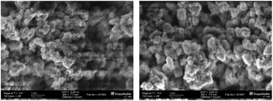 |
| | Fig. 5 SEM images of the TiO2 surface in the microchannels before (left) and after (right) use in the FFMR (length scale: 1 μm). | |
In conjunction with SEM analysis energy dispersive X-ray (EDX) analysis was performed as well to check the composition of the catalyst material in the microchannels before and after its use in flow synthesis (Table 1 and ESI†). In both cases titanium and oxygen represent the major share of the detected elements in the correct ratio for TiO2, whereas the oxygen share is slightly higher in the unused sample. This portion as well as the carbon content of 2.55 atom% can be attributed to residues of the binder poly(vinyl alcohol) from catalyst preparation. The used sample shows a significant carbon and fluorine content of 3.41 atom% and 3.20 atom%, respectively. Both elements result from the last experiments performed with trifluoromethylated benzenediazonium salts (vide infra). A low content of iron with 0.62 atom% and 1.05 atom%, respectively, most likely results from the stainless steel reaction plate as a catalyst carrier.
Table 1 Element composition of catalyst material inside the microchannels as analysed by EDX
| Element |
Before use in FFMR, atom% |
After use in FFMR, atom% |
| C |
2.55 |
3.41 |
| O |
70.06 |
65.30 |
| F |
— |
3.20 |
| P |
0.35 |
0.23 |
| S |
0.12 |
— |
| Ti |
26.30 |
26.67 |
| Cr |
— |
0.13 |
| Fe |
0.62 |
1.05 |
Lab plant design and reactor integration
The FFMR is part of an integrated multi-purpose lab plant for different reactor types (FFMR and tube-in-tube flow reactor) (Fig. 6). The heat exchanger of the FFMR is connected to a water-filled thermostat for maintaining the temperature of the reaction plate at 20 °C (see the ESI† for details of the flow chart). This external cooling is necessary since prolonged LED irradiation can lead to heating of the reaction plate and solvent evaporation in the microchannels which results in falsification of the residence time of the reaction solution in the microreactor. The starting material solution is pumped with a HPLC pump into the reactor at a flow rate fliq = 0.5 mL min−1. A nitrogen gas stream is fed in counter-flow to the liquid stream into the FFMR. This inert gas flow of approx. 10 mL min−1 was used to support the self-draining of the reactor. All LEDs (actinic blue, royal blue, cold-white) used for the experiments are installed on an aluminium heat sink, which can be fixed magnetically in front of the inspection window of the FFMR (Fig. 1).
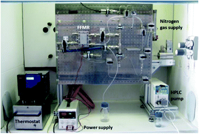 |
| | Fig. 6 FFMR lab plant with a HPLC pump, thermostat, nitrogen gas supply and power supply of the LED array. | |
Reaction evaluation and substrate scope
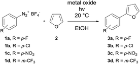
The first set of experiments was performed with 4-fluorobenzenediazonium salt 1a and furan as a heterocycle. In order to investigate the necessity and type of photocatalyst several runs were performed with different metal oxides using royal blue light (455 nm) at a flow rate fliq = 0.5 mL min−1 (Table 2). In the case of TiO2 a yield of 79% was obtained (entry 1), whereas for ZnO and Bi2O3 only low yields could be achieved (entries 2 & 3).43 In the case of a blank reaction plate without metal oxide no reaction took place (entry 4). The impact of the light source was investigated as well with the reaction plate carrying TiO2. The use of cold-white light (6500 K, entry 5) and actinic blue (410 nm, entry 6) as well as the absence of light as the blank test (entry 7) was ineffective compared to royal blue light, which provided a maximum light intensity at the absorption range of the photoactive TiO2 azoether at approx. 450 nm.16 Therefore, all further experiments were performed with royal blue light for irradiation and TiO2 as the catalyst material. Under these conditions the furan series was completed with three more diazonium salt derivatives showing approximately the same or better yields compared to the batch synthesis (entries 8–10, Table 2).
Table 2 Evaluation of the reaction conditions and substrate scope for furan seriesa
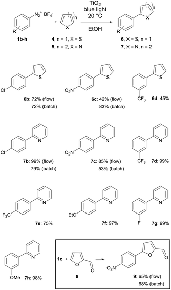
The next set of experiments was performed with thiophene as the heterocycle for C–H arylation (Table 3). In the case of 6b the same yield of 72% was obtained by flow and batch synthesis. The nitro derivative 6c, however, gave a considerably lower yield of 42% compared to 83% in the batch synthesis. A moderate yield of 45% was achieved for the trifluoromethylated compound 6d (Table 3). Pyridine was used as the last heterocycle. Surprisingly, the pyridine series yielded in continuous-flow far better results than via the batch synthesis. In the case of 7b 99% yield was obtained compared to 79% in batch. The same trend was observed for 7c with 85% yield in flow synthesis compared to 53% in batch. Therefore, a broader substrate scope was investigated. Except for 7e (p-CF3) with 75% yield excellent yields of up to 99% were obtained for all other pyridine compounds (Table 3). To complete the substrate scope, the precursor of dantrolene, an API for muscle relaxation, was synthesized as well in continuous-flow mode (Table 3, framed). Furfural (8) was used as a heterocycle with 1c as a diazonium salt under standard reaction conditions with fliq = 0.5 mL min−1, T = 20 °C and royal blue light with TiO2 as a photocatalyst. A slightly lower yield of 65% was achieved for 9 in continuous-flow mode compared to 68% in batch. The conversion of 9 with 1-aminohydantoin hydrochloride provided dantrolene in an excellent yield of 92% (see the ESI†).
Table 3 Reaction conditions and substrate scope for thiophene and pyridine seriesa
Reaction conditions: 5 mmol 1b–h in 100 mL EtOH/thiophene or pyridine (1![[thin space (1/6-em)]](https://www.rsc.org/images/entities/char_2009.gif) : :![[thin space (1/6-em)]](https://www.rsc.org/images/entities/char_2009.gif) 1, v/v); T = 20 °C; fliq = 0.5 ml min−1; amount of immobilized metal oxide: m(TiO2) = 24 mg; yield of continuous-flow synthesis after chromatographic purification; yield of batch synthesis, see ref. 16. 1, v/v); T = 20 °C; fliq = 0.5 ml min−1; amount of immobilized metal oxide: m(TiO2) = 24 mg; yield of continuous-flow synthesis after chromatographic purification; yield of batch synthesis, see ref. 16.
|
|
Long-term run
The long-term run was performed with 4-trifluoromethylbenzene diazonium salt (1e) in EtOH and pyridine as heteroarenes. Standard reaction conditions were applied as well in this experiment with T = 20 °C, fliq = 0.5 mL min−1, royal blue light and TiO2 immobilized in the microchannels. During the complete run time of 180 min nine samples were taken from the reactor outlet and mixed with 4-trifluoromethylbenzyl alcohol as the internal standard (19F NMR (56 MHz) δ = −65.99; s, 3F) in DMSO-d6. Over the complete run time the process was performing constant with a mean conversion of 77%, which is in good agreement with the yield of 75% achieved with the synthesis during substrate scope evaluation (Fig. 7). The NMR spectra revealed only the product 7e (19F NMR (56 MHz) δ = −66.44) and the diazoether of 1e with ethanol being the intermediate compound of the synthesis (19F NMR (56 MHz) δ = −66.28). It has to be pointed out that reaction evaluation and long-term run has been performed with solely one plate with immobilized TiO2. This fact proves the exceptional durability and reusability of the immobilized catalyst.
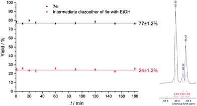 |
| | Fig. 7 Constant yields for 1d during long-term run over 180 minutes (left) and part of the 19F NMR spectra of the sample taken after 30 minutes (right). | |
Flow reactor performance
The specific reactor performance L is an important parameter to characterize chemical processes performed using different reactor systems. In the case of a batch reactor system the specific reactor performance Lbatch is usually described by:44| |  | (1) |
with cstarting material as the molar concentration of the starting material, Yproduct as the yield of the desired product and tR as the reaction time. The dead time tD can be assumed for filling the reaction vial, starting the reaction and quenching the reaction afterwards. The specific reactor performance of the FFMR LFFMR can be calculated by:44| |  | (2) |
with τ as the residence time of the reaction solution in contact with the catalyst material. The residence time τ can be calculated by:45| |  | (3) |
with N as the number of microchannels on the reaction plate, Vc as the irradiated volume of the reaction solution in one microchannel, W as the width of a microchannel, L as the microchannel length, δ as the liquid thin film thickness and fliq as the flow rate of the reaction solution. The liquid thin film thickness δ can be expressed by the Nusselt equation:45,46| |  | (4) |
with μliq as the dynamic viscosity of the reaction solution, ρliq as the density of the reaction solution and g as the gravitational constant. The conversion of 4-chlorobenzenediazonium salt (1b) with pyridine to 2-(4-chlorophenyl)pyridine (7b) was chosen for comparing batch and continuous-flow synthesis. In Table 4 all necessary data are compiled for the calculation of the specific reactor performance of the batch system and the continuous-flow reactor. In the case of the batch synthesis a specific reactor performance of Lbatch = 5.4 × 10⁻⁵ mol L−1 min−1 was calculated. For the continuous-flow synthesis in the FFMR a specific reactor performance of LFFMR = 0.32 mol L−1 min−1 was calculated. The extreme performance increase by a factor of approx. 6000, solely by switching from batch to continuous-flow mode, can be attributed to the following reasons. The FFMR offers a strongly improved irradiation of the reaction solution compared to the batch synthesis. The royal blue LED array provides solely the light exactly matching to the absorption range of the TiO2 diazoether. During the process the volume of the reaction solution inside the microchannels is quite small (approx. 0.08 mL) and in intense contact with the fully irradiated catalyst surface. This efficient combination is in clear contrast to the batch synthesis where the complete catalyst suspension volume is irradiated by a rather unspecific light source.
Table 4 Data for and results of the calculation of the specific reactor performance L
| |
Batcha |
Flow |
Unit |
|
Data extracted from ref. 16.
Estimated dead time.
The full length of a microchannel is used for the calculation, since the dual role of TiO2 (diazoether formation and photocatalysis) is not only limited to the directly and fully irradiated length of 54 mm.
Data extracted from ref. 47.
|
| Molar concentration cstarting material |
0.05 |
0.05 |
mol L−1 |
| Yield Yproduct |
79% |
99% |
— |
| Number N of microchannels |
— |
32 |
— |
| Microchannel width, W |
— |
600 |
μm |
| Channel length, L |
— |
78c |
mm |
| Gravitational constant, g |
— |
9.81 |
m s−2 |
| Liquid flow rate, fliq |
— |
0.5 |
mL min−1 |
| Dynamic viscosity, μ |
— |
0.8839d |
g mL−1 |
| Density, ρ |
— |
0.8910d |
mPa s |
| Reaction time, tR |
720 |
— |
min |
| Dead time, tD |
15b |
— |
min |
| Liquid thin film thickness, δ |
— |
50.9 |
μm |
| Residence time, τ |
— |
9.1 |
s |
| Specific reactor performance, L |
5.4 × 10⁻⁵ |
0.32 |
mol L−1 min−1 |
Conclusions
For the first time the falling film microreactor technology was successfully applied to a photochemically catalysed reaction with TiO2 as an immobilized photocatalyst in the microchannels of a continuous-flow reactor. A wide variety of arenediazonium salts were used as the starting material for blue light mediated C–H arylation of heteroarenes in continuous-flow mode. Furan, thiophene and pyridine as well as furfural were converted into the desired products with good to excellent yields up to 99%. A long-term run over 180 min was successfully performed as well in order to demonstrate the catalyst performance. Detailed XRD, SEM and EDX analyses of the catalyst material before and after calcination and its use in the microreactor, respectively, proved the excellent stability and usability of TiO2 as an immobilized photocatalyst in a continuous-flow microreactor. The transfer of the C–H arylation of heteroarenes from batch mode to continuous-flow revealed a boost in the specific reactor performance up to a factor of 6000. This strong increase can be attributed to the improved irradiation and substrate–catalyst–light interaction on the microstructured surface of the continuous-flow reactor. These results clearly show the major advantages for photochemistry when performed in a microstructured environment.
Experimental
Catalyst preparation and immobilization
A slurry-washcoat process was used for the immobilization of catalyst material on the FFMR reaction plate. The preparation of TiO2, ZnO and Bi2O3 washcoats was carried out according to literature procedures.41,48 The method is exemplified here for TiO2. 2.5 g of poly(vinyl alcohol) (PVA) used as a binder (Sigma Aldrich, Mowiol 40–88) were mixed with 42.5 mL of distilled water and stirred at 65 °C until PVA had completely dissolved (approx. 2–3 h). 5 g of TiO2 (Alfa Aesar, 45603, anatase modification) and 0.375 g concentrated acetic acid were added to the solution and stirred for 3 h at 65 °C, and finally at room temperature for 2–3 days, until the suspension became homogeneous and dense.
All reaction plates were cleaned with citric acid solution (10 wt% in water) under ultrasound treatment. After rinsing the cleaned plates with distilled water, they were heated in an oven at 800 °C. Prior to the deposition of the washcoat in the microchannels, the area on the reaction plate not to be coated with a catalyst was covered with an adhesive tape. Afterwards the microchannels were completely filled with the prepared suspension and the excess of the suspension was wiped off. After drying at room temperature in air, the coated plates were calcined at 450 °C for 6 h.
Catalyst analysis
The surface roughness of the catalyst layer inside the microchannels was measured with a NanoFocus AF 2000. The surface area and the pore diameter of the catalyst material were determined before and after calcination. Low temperature nitrogen physisorption was performed with Sorptomatic 1990 (Carlo Erba Instruments) automatic apparatus. The obtained information was used for the calculations of the surface area and the pore diameter by applying the BET and BJH methods. Transmission electron microscopy (TEM) images were recorded with a Zeiss Libra® 120 on copper grids with a carbon thin film (CF300-CU, EM Science). X-ray powder diffraction (XRD) patterns were recorded from powders prepared between two stripes of 3 M Scotch tape using a Siemens D5000 equipped with a Ge (111) monochromator (Huber 611 Guinier monochromator) and a Braun M50 position sensitive detector in transmission mode. Scanning electron microscopy (SEM) images were taken with a Zeiss Leo 1550 VP Field Emission Scanning Electron Microscope. The reaction plates containing TiO2 were scanned without any sample preparation. The acceleration voltage was 5.00 kV, and the working distance was between 7.7 and 8.0 mm. Energy Dispersive X-ray (EDX) analysis was performed with an Oxford INCA II setup.
General procedure for the TiO2 catalyzed arylation in continuous-flow
Aryldiazonium tetrafluoroborates 1a–h were synthesized according to literature procedures (for details, see the ESI†). The appropriate salt was dissolved in a solvent mixture of EtOH and the corresponding heterocycle (furan, thiophene, pyridine or furfural, v![[thin space (1/6-em)]](https://www.rsc.org/images/entities/char_2009.gif) :
:![[thin space (1/6-em)]](https://www.rsc.org/images/entities/char_2009.gif) v 1
v 1![[thin space (1/6-em)]](https://www.rsc.org/images/entities/char_2009.gif) :
:![[thin space (1/6-em)]](https://www.rsc.org/images/entities/char_2009.gif) 1, 50 mM). The resulting mixture was stirred until complete solvation of the diazonium salt. Then, the mixture was pumped into the falling film microreactor for collapsing down into the microchannels. As soon as the reaction solution equally rinsed all microchannels irradiation was started by switching on the LED array connected to the FFMR. The crude reaction mixture was collected and filtered over a short plug of silica and flushed with ethyl acetate. If necessary, the final products were further purified using flash column chromatography on silica gel (eluent cyclohexane/ethyl acetate).
1, 50 mM). The resulting mixture was stirred until complete solvation of the diazonium salt. Then, the mixture was pumped into the falling film microreactor for collapsing down into the microchannels. As soon as the reaction solution equally rinsed all microchannels irradiation was started by switching on the LED array connected to the FFMR. The crude reaction mixture was collected and filtered over a short plug of silica and flushed with ethyl acetate. If necessary, the final products were further purified using flash column chromatography on silica gel (eluent cyclohexane/ethyl acetate).
Acknowledgements
T. H. R. would like to thank Dr Raphael Thiermann for TEM analysis, Anja Himmelsbach for SEM and EDX analysis and Gitta Hasert for nitrogen physisorption analysis (all Fraunhofer ICT-IMM). This research has received funding from the European Research Council under the European Union's Seventh Framework Programme (FP/2007-2013)/ERC Grant Agreement no. 617044 (SunCatChem).
Notes and references
- Y. Shiraishi and T. Hirai, J. Photochem. Photobiol., C, 2008, 9, 157–170 CrossRef CAS.
- M. Chong, B. Jin, C. Chow and C. Saint, Water Res., 2010, 44, 2997 CrossRef CAS PubMed.
- N. Hoffmann, Aust. J. Chem., 2015, 68, 1621–1639 CrossRef CAS.
- A. Molinari, M. Montoncello, H. Rezala and A. Maldotti, Photochem. Photobiol. Sci., 2009, 8, 613–619 CAS.
- N. Li, X. Lang, W. Ma, H. Ji, C. Chen and J. Zhao, Chem. Commun., 2013, 49, 5034–5036 RSC.
- C. Bottecchia, N. Erdmann, P. Tijssen, L.-G. Milroy, L. Brunsveld, V. Hessel and T. Noël, ChemSusChem, 2016, 9, 1781–1785 CrossRef CAS PubMed.
- C. Vila and M. Rueping, Green Chem., 2013, 15, 2056–2059 RSC.
- V. Bhat, P. Duspara, S. Seo, N. Bakar and M. Greaney, Chem. Commun., 2015, 51, 4383–4385 RSC.
- M. Rueping, J. Zoller, D. Fabry, K. Poscharny, R. Koenigs, T. Weirich and J. Mayer, Chem. – Eur. J., 2012, 18, 3478–3481 CrossRef CAS PubMed.
- G. Palmisano, E. García-López, G. Marcí, V. Loddo, S. Yurdakal, V. Augugliaro and L. Palmisano, Chem. Commun., 2010, 46, 7074–7089 RSC.
- B. Pal, S. Ikeda, H. Kominami, Y. Kera and B. Ohtani, J. Catal., 2003, 217, 152–159 CAS.
- S. Füldner, R. Mild, H. Siegmund, J. Schroeder, M. Gruber and B. König, Green Chem., 2010, 12, 400–406 RSC.
- M. Cherevatskaya, M. Neumann, S. Füldner, C. Harlander, S. Kümmel, S. Dankesreiter, A. Pfitzner, K. Zeitler and B. König, Angew. Chem., Int. Ed., 2012, 51, 4062–4066 CrossRef CAS PubMed.
- X. Lang, J. Zhao and X. Chen, Angew. Chem., Int. Ed., 2016, 55, 4697–4700 CrossRef CAS PubMed.
- X. Lang, W. Hao, W. Leow, S. Li, J. Zhao and X. Chen, Chem. Sci., 2015, 6, 5000–5006 RSC.
- J. Zoller, D. Fabry and M. Rueping, ACS Catal., 2015, 5, 3900–3904 CrossRef CAS.
- D. Cambié, C. Bottecchia, N. Straathof, V. Hessel and T. Noël, Chem. Rev., 2016, 116, 10276–10341 CrossRef PubMed.
-
T. Rehm, in Flow Chemistry - Applications, ed. F. Darvas, G. Dorman and V. Hessel, DeGruyter, Berlin, 2014, ch. 3, p. 64 Search PubMed.
- T. Van Gerven, G. Mul, J. Moulijn and A. Stankiewicz, Chem. Eng. Process., 2007, 46, 781–789 CrossRef CAS.
- B. Hook, W. Dohle, P. Hirst, M. Pickworth, M. Berry and K. Booker-Milburn, J. Org. Chem., 2005, 70, 7558 CrossRef CAS PubMed.
- L. Elliot, J. Knowles, P. Koovits, K. Maskill, M. Ralph, G. Lejeune, L. Edwards, R. Robinson, I. Clemens, B. Cox, D. Pascoe, G. Koch, M. Eberle, M. Berry and K. Booker-Milburn, Chem. – Eur. J., 2014, 20, 15226 CrossRef PubMed.
- J. Schachtner, P. Bayer and A. Jacobi von Wangelin, Beilstein J. Org. Chem., 2016, 12, 1798–1811 CrossRef CAS PubMed.
- G. Kreisel, S. Meyer, D. Tietze, T. Fidler, G. Gorges, A. Kirsch, B. Schäfer and S. Rau, Chem. Ing. Tech., 2007, 79, 153 CrossRef CAS.
-
G. Held, Introduction to Light Emitting Diode Technology and Applications, CRC Press, Boca Raton, 2009 Search PubMed.
-
W. Ehrfeld, V. Hessel and H. Löwe, Microreactors, Wiley-VCH, Weinheim, 2000 Search PubMed.
-
V. Hessel, A. Renken, J. Schouten and J.-I. Yoshida, Micro Process Engineering, Wiley-VCH, Weinheim, 2009 Search PubMed.
- J.-N. Tourvieille, F. Bornette, R. Philippe, Q. Vanderberghe and C. de Bellefon, Chem. Eng. J., 2013, 227, 182 CrossRef CAS.
- C. Mallia and I. Baxendale, Org. Process Res. Dev., 2016, 20, 327 CrossRef CAS.
- Y. Matsushita, N. Ohbab, S. Kumadab, K. Sakeda, T. Suzuki and T. Ichimura, Chem. Eng. J., 2008, 135S, S303–S308 CrossRef.
- S. Fuse, N. Tanabe, M. Yoshida, H. Yoshida, T. Doi and T. Takahashi, Chem. Commun., 2010, 46, 8722–8724 RSC.
- C. Park, R. Maurya, J. Lee and D.-P. Kim, Lab Chip, 2011, 11, 1941–1945 RSC.
- O. Shvydkiv, A. Yavorskyy, S. Tan, K. Nolan, N. Hoffmann, A. Youssef and M. Oelgemöller, Photochem. Photobiol. Sci., 2011, 10, 1399–1404 CAS.
- K. Yeong, A. Gavriilidis, R. Zapf and V. Hessel, Chem. Eng. Sci., 2004, 59, 3491 CrossRef.
- M. Zanfir, A. Gavriilidis, C. Wille and V. Hessel, Ind. Eng. Chem. Res., 2005, 44, 1742 CrossRef CAS.
- H. Zhang, G. Chen, J. Yue and Q. Yuan, AIChE J., 2009, 55, 1110 CrossRef CAS.
- M. Al-Rawashdeh, V. Hessel, P. Löb, K. Mevissen and F. Schönfeld, Chem. Eng. Sci., 2008, 63, 5149 CrossRef CAS.
- H. Ehrlich, D. Linke, K. Morgenschweis, M. Baerns and K. Jähnisch, Chimia, 2002, 56, 647 CrossRef.
- K. Jähnisch and U. Dingerdissen, Chem. Eng. Technol., 2005, 28, 426 CrossRef.
- O. Shvydkiv, C. Limburg, K. Nolan and M. Oelgemöller, J. Flow Chem., 2012, 2, 52 CrossRef CAS.
- T. H. Rehm, S. Gros, P. Löb and A. Renken, React. Chem. Eng., 2016, 1, 636 CAS.
- R. Zapf, G. Kolb, H. Pennemann and V. Hessel, Chem. Eng. Technol., 2006, 29, 1509–1512 CrossRef CAS.
- E.-Y. Kim, D. Kim and B.-T. Ahn, Bull. Korean Chem. Soc., 2009, 30, 193–196 CrossRef CAS.
- Reaction plates with ZnO and Bi2O3 as immobilized metal oxides were prepared by the same method as the reaction plate carrying TiO2.
- T. H. Rehm, C. Berguerand, S. Ek, R. Zapf, P. Löb, L. Nikoshvili and L. Kiwi-Minsker, Chem. Eng. J., 2016, 293, 345–354 CrossRef CAS.
- N. Steinfeldt, R. Abdallah, U. Dingerdissen and K. Jähnisch, Org. Process Res. Dev., 2007, 11, 1025–1031 CrossRef CAS.
- M. van Dam, J.-P. Corriou, N. Midoux, A. Lamine and S. Roizard, Chem. Eng. Sci., 1999, 54, 5311 CrossRef CAS.
- E. Dikio, S. Nelana, D. Isabirye and E. Ebenso, Int. J. Electrochem. Sci., 2012, 7, 11101–11122 CAS.
- R. Zapf, C. Becker-Willinger, K. Berresheim, H. Bolz, H. Gnaser, V. Hessel, G. Kolb, A.-K. Pannwitt and A. Ziogas, Trans. IChemE., 2003, 81A, 721–729 CrossRef.
Footnote |
| † Electronic supplementary information (ESI) available: Catalyst preparation and immobilisation, surface roughness, TEM, nitrogen physisorption, XRD, SEM, EDX, lab plant description and flow chart, synthesis of aryldiazonium salts, 19F NMR analysis during long-term run, and product characterization: 1H-, 13C-, and 19F-NMR spectroscopy. See DOI: 10.1039/c7gc00497d |
|
| This journal is © The Royal Society of Chemistry 2017 |
Click here to see how this site uses Cookies. View our privacy policy here.  Open Access Article
 c,
Martin
Panthöfer
c,
Magnus
Rueping
c,
Martin
Panthöfer
c,
Magnus
Rueping
 *a and
Thomas H.
Rehm
 *b
*b


![[thin space (1/6-em)]](https://www.rsc.org/images/entities/char_2009.gif) :
:![[thin space (1/6-em)]](https://www.rsc.org/images/entities/char_2009.gif) 1, v/v); T = 20 °C; fliq = 0.5 ml min−1.
b Amount of immobilized metal oxide: m(TiO2) = 24 mg, m(ZnO) = 24 mg, m(Bi2O3) = 27 mg.
c Electrical power Pele ≈ 2.4 W.
d Yield after chromatographic purification.
e See ref. 16.
1, v/v); T = 20 °C; fliq = 0.5 ml min−1.
b Amount of immobilized metal oxide: m(TiO2) = 24 mg, m(ZnO) = 24 mg, m(Bi2O3) = 27 mg.
c Electrical power Pele ≈ 2.4 W.
d Yield after chromatographic purification.
e See ref. 16.


![[thin space (1/6-em)]](https://www.rsc.org/images/entities/char_2009.gif) :
:![[thin space (1/6-em)]](https://www.rsc.org/images/entities/char_2009.gif) v 1
v 1![[thin space (1/6-em)]](https://www.rsc.org/images/entities/char_2009.gif) :
:![[thin space (1/6-em)]](https://www.rsc.org/images/entities/char_2009.gif) 1, 50 mM). The resulting mixture was stirred until complete solvation of the diazonium salt. Then, the mixture was pumped into the falling film microreactor for collapsing down into the microchannels. As soon as the reaction solution equally rinsed all microchannels irradiation was started by switching on the LED array connected to the FFMR. The crude reaction mixture was collected and filtered over a short plug of silica and flushed with ethyl acetate. If necessary, the final products were further purified using flash column chromatography on silica gel (eluent cyclohexane/ethyl acetate).
1, 50 mM). The resulting mixture was stirred until complete solvation of the diazonium salt. Then, the mixture was pumped into the falling film microreactor for collapsing down into the microchannels. As soon as the reaction solution equally rinsed all microchannels irradiation was started by switching on the LED array connected to the FFMR. The crude reaction mixture was collected and filtered over a short plug of silica and flushed with ethyl acetate. If necessary, the final products were further purified using flash column chromatography on silica gel (eluent cyclohexane/ethyl acetate).


