 Open Access Article
 This Open Access Article is licensed under a
 Creative Commons Attribution 3.0 Unported Licence
Asymmetric electroosmotic pumping across porous media sandwiched with perforated ion-exchange membranes
A.
Yaroshchuk
 *ab,
E. E.
Licón
b,
E. K.
Zholkovskiy
c,
M. P.
Bondarenko
c and
T.
Heldal
d
*ab,
E. E.
Licón
b,
E. K.
Zholkovskiy
c,
M. P.
Bondarenko
c and
T.
Heldal
d
aICREA, pg. L. Companys 23, 08010 Barcelona, Spain
bDept of Chemical Engineering, Polytechnic University of Catalonia, Av. Diagonal 647, 08028 Barcelona, Spain. E-mail: andriy.yaroshchuk@upc.edu
cInstitute of Bio-Colloid Chemistry, National Academy of Sciences of Ukraine, Vernadskiy Ave. 42, 03142, Kyiv, Ukraine
dOsmotex AG, Schützenstrasse 3, 8800 Thalwil, Switzerland
First published on 25th January 2017
Abstract
To have non-zero net flow in AC electroosmotic pumps, the electroosmosis (EO) has to be non-linear and asymmetric. This can be achieved due to ionic concentration polarization. This is known to occur close to micro-/nano-interfaces provided that the sizes of the nanopores are not too large compared to the Debye screening length. However, operation of the corresponding EO pumps can be quite sensitive to the solution concentration and, thus, unstable in practical applications. Concentration polarization of ion-exchange membranes is much more robust. However, the hydraulic permeability of the membrane is very low, which makes EO flows through them extremely small. This communication shows theoretically how this problem can be resolved via making scarce microscopic perforations in an ion-exchange membrane and putting it in series with an EO-active nano-porous medium. The problem of coupled flow, concentration and electrostatic-potential distributions is solved numerically by using finite-element methods. This analysis reveals that even quite scarce perforations of micron-scale diameters are sufficient to observe practically-interesting EO flows in the system. If the average distance between the perforations is smaller than the thickness of the EO-active layer, there is an effective homogenization of the electrolyte concentration and hydrostatic pressure in the lateral direction at some distance from the interface. The simulations show this distance to be somewhat lower than the half-distance between the perforations. On the other hand, when the surface fraction of perforations is sufficiently small (below a fraction of a percent) this “homogeneous” concentration is considerably reduced (or increased, depending on the current direction), which makes the EO strongly non-linear and asymmetric. This analysis provides initial guidance for the design of high-productivity and inexpensive AC electroosmotic pumps.
Introduction
Electro-osmotic pumps are useful because they have no moving parts and can be easily miniaturized for applications in micro-Total-Analysis Systems (μTAS).1 Another interesting application is EO-generated “active” moisture removal through engineered sports tissues.2,3Alternating Current EO pumps (ACEO) have the potential advantage of exhibiting no electrode reactions (provided that the voltage is not too high and/or the frequency is not too low). The absence of electrode reactions is a sine-qua-non in the application of “active” moisture removal because of the direct contact of the material with the human body.
For an ACEO pump to produce net flows (over the AC period), the EO has to be asymmetric (its rate is dependent on the current direction). Over the last decade, considerable efforts have been devoted to the exploration of ACEO based on the concept of travelling-wave ACEO using asymmetric electrode arrays.4–10
To be asymmetric, the EO must be non-linear. One of the mechanisms of EO non-linearity is due to ionic concentration polarization (CP). Recently, this has been studied extensively both theoretically and experimentally in micro-/nano-fluidic systems (see, for example, this review11). The mechanism of CP-induced EO non-linearity is simple. In sufficiently fine-porous media (or narrow nano-channels), the ion transport numbers are noticeably different from the electrolyte solution (due to the existence of EDLs whose diffuse parts make up a non-negligible portion of pore space). Therefore, current passage gives rise to changes in electrolyte concentration at and around the interfaces between the media and electrolyte solutions. The rate of electroosmosis increases with decreasing concentration. Due to the concentration polarization, salt concentration either decreases or increases close to the interfaces depending on the current direction and sign of the surface charge. This can give rise to non-linear EO. Additionally, if the system is asymmetric, the rate of non-linear EO in one current direction can be different from its rate in the other. As a result, there can be net EO flows in response to alternating currents with zero net electric charge transfer.
The required asymmetry occurs, for example, in nano-funnels,12 or in track-etched membranes with conical nano-pores,13–15 and, indeed, net ACEO pumping has been demonstrated experimentally for such systems. However, for the concentration polarization to be sufficiently strong, the smallest dimension of the nano-channel cannot be too large compared to the Debye screening length, otherwise the concentration polarization is “suppressed” by electroosmosis itself.16 This can easily make the system operation unstable in practical applications. Additionally, in the context of nano-engineered devices, there are issues of low productivity and extremely high cost.
In this communication, we will show how the concentration–polarization phenomena can be largely “decoupled” from the (nano)-porous medium but still influence the electroosmosis through it in the desired way. This can be achieved by using a novel micro-engineered layered material.
Current-induced concentration polarization is well-known to occur close to the surfaces of ion-exchange membranes, and it is actually the physico-chemical mechanism of electrodialysis.17 Ion-exchange membranes are usually polymeric materials with considerable concentrations of dissociable groups being a part of (or being covalently attached to) the polymer backbone. In water (and/or other polar solvents) these groups dissociate and give rise to immobile (fixed) electric charges. Due to the electroneutrality requirement, their charge is compensated by mobile counterions whose concentration in the membrane phase can be considerably higher than in the equilibrium solution. Conversely, the concentration of ions of opposite charge (co-ions) can be considerably reduced. This can give rise to a pronounced asymmetry in the permeability of ion-exchange membranes to counterions and co-ions, thus making the conductance of ion-exchange membranes practically unipolar. Due to the very small pore size and high ion-exchange capacity (fixed-charge concentration) of typical ion-exchange membranes, this can occur even up to quite high salinities. Therefore, if an EO-active porous medium is in direct contact with an ion-exchange membrane, the salt concentration at the interface between them decreases or increases (depending on the current direction) even in solutions of quite high salinity. The pore size of the EO-active medium is not so crucial in this case (in contrast to single nano-porous media where both the CP and EO are controlled by the same material). This layered arrangement would potentially make the EO strongly non-linear and asymmetric, provided that the ion-exchange membrane is on one side of the EO-active medium only. However, the hydraulic permeability of conventional ion-exchange membranes is extremely low. Therefore, with them, the EO-active medium would be working in the mode of EO pressure where gradients of hydrostatic pressure arise inside the “sandwich” but the volume flow through it is negligible.
The idea is to considerably increase the hydraulic permeability of the ion-exchange layer via making microscopic pores/channels in it. This arrangement is schematically depicted in Fig. 1.
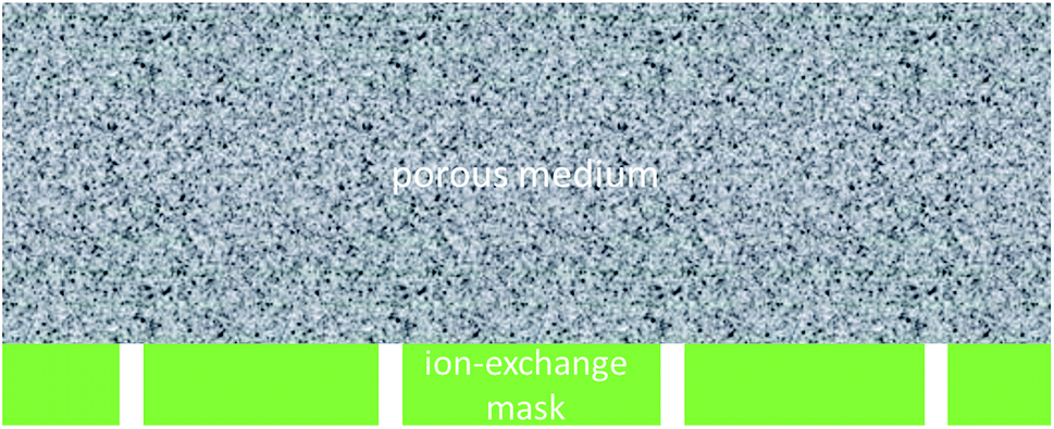 | ||
| Fig. 1 Sketch of a nano-porous layer sandwiched with a perforated ion-exchange mask (not to scale). | ||
If the average distance between the openings is essentially smaller than the thickness of the EO-active layer, one can expect effective homogenization of electrolyte concentration in the lateral direction at some distance from the interface. At the same time, when the surface fraction of “perforations” is sufficiently low, the concentration–polarization phenomena may not be critically affected by the presence of the “openings”. To be more precise (as shown below), the electroosmosis itself does noticeably affect the concentration polarization (and, for example, makes the limiting current disappear), but the EO remains a strongly non-linear and asymmetric function of current density, nonetheless.
We will investigate this system theoretically via analysis of the limiting cases and numerical simulations and show that this physical picture is correct.
Theory
Problem formulation
To our knowledge, EO in the system of interest has never been studied before. Therefore, we will use the simplest non-trivial problem formulation. We will consider a symmetrical (1![[thin space (1/6-em)]](https://www.rsc.org/images/entities/char_2009.gif) :1) salt with ions of equal mobilities, we will neglect streaming current, and we will describe the EO according to the Smoluchowski model (no surface conductance and no Electrical Double Layer (EDL) overlap). We will also consider the zeta-potential constant (independent of salt concentration). Most of these approximations are legitimate if the pores of the EO-active medium are much larger than the Debye screening length. The latter is about 3 nm in length in practically-relevant centi-molar solutions (10 mM). Thus, if the pore size is much larger than that (for example, 200 nm as in the simulations below) the overlap of EDLs can be clearly neglected. Besides, if the pore-surface (zeta) potential is not too high, one can also neglect the additional conductance due to the counterions that are attracted to the pore surface (surface conductance) as compared to the conductance in the bulk of the pore volume. The streaming contribution to the current is also proportional to the fraction of the pore volume occupied by the EDLs, and can be neglected for the same reason.
:1) salt with ions of equal mobilities, we will neglect streaming current, and we will describe the EO according to the Smoluchowski model (no surface conductance and no Electrical Double Layer (EDL) overlap). We will also consider the zeta-potential constant (independent of salt concentration). Most of these approximations are legitimate if the pores of the EO-active medium are much larger than the Debye screening length. The latter is about 3 nm in length in practically-relevant centi-molar solutions (10 mM). Thus, if the pore size is much larger than that (for example, 200 nm as in the simulations below) the overlap of EDLs can be clearly neglected. Besides, if the pore-surface (zeta) potential is not too high, one can also neglect the additional conductance due to the counterions that are attracted to the pore surface (surface conductance) as compared to the conductance in the bulk of the pore volume. The streaming contribution to the current is also proportional to the fraction of the pore volume occupied by the EDLs, and can be neglected for the same reason.
The assumption of a constant zeta-potential is unrelated to the pore size and somewhat artificial because usually the zeta-potential increases in absolute value with decreasing concentration. However, this approximation makes possible the decoupling of the hydraulic problem, which helps a lot with elucidating the physics. At the same time, from the analysis below, it will be seen that disregarding the possible increase in the absolute value of the zeta-potential with decreasing salt concentration most probably leads to underestimating the EO asymmetry, therefore with a more realistic model the effect can probably only be stronger. This will be investigated in future studies.
In the above approximations, for the electric-current density, ![[I with combining right harpoon above (vector)]](https://www.rsc.org/images/entities/i_char_0049_20d1.gif) , volume flux,
, volume flux, ![[J with combining right harpoon above (vector)]](https://www.rsc.org/images/entities/i_char_004a_20d1.gif) v, and salt flux, s, we can write down these constitutive relationships
v, and salt flux, s, we can write down these constitutive relationships
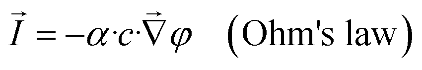 | (1) |
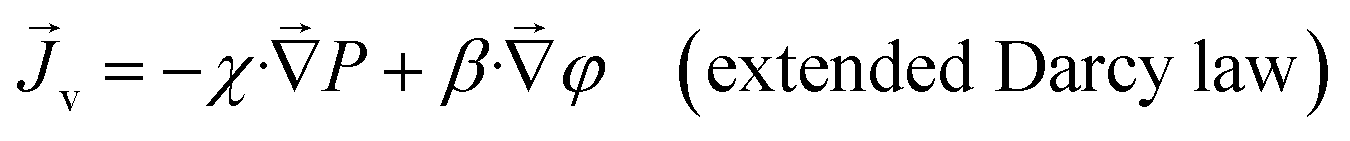 | (2) |
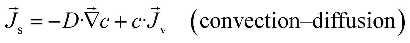 | (3) |
 | (4) |
 | (5) |
The electric-current density, volume flux and salt flux must be conservative
| div() = 0 | (6) |
| div(v) = 0 | (7) |
| div(s) = 0 | (8) |
and by substituting eqn (1)–(3) to (6)–(8) we obtain
 | (9) |
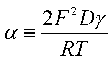
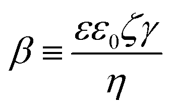
| β·∇2φ − χ·∇2P = 0 | (10) |
 | (11) |
To model the ion-exchange layer, in the first approximation we consider an infinitely thin but hydraulically impermeable and ideally perm-selective ion-exchange film with negligible ohmic resistance. The latter assumptions correspond to the limiting case of very large fixed-charge densities. In such a hydraulic “mask”, there are openings (holes) where the surface of the porous medium is exposed (uncovered). In this study, we consider a layered system surrounded by sufficiently large volumes of solution so that the pressure gradients are localized exclusively inside the system. The external hydrostatic-pressure difference between the solutions separated by the “sandwich” is zero (classical conditions of EO) and the zero pressure condition is supposed to extend to the system’s external surfaces. The salt concentration is the same in both solutions and extends right up to the system’s surfaces (external concentration polarization is disregarded). The electrostatic potential is also assumed to be set immediately at the system’s surfaces, but there is a potential difference between the solutions separated by the system (applied voltage). This is the only external driving force. The system and the coordinates are schematically shown in Fig. 2.
 | ||
| Fig. 2 Computational domain, coordinates and dimensions. | ||
Accordingly, the boundary conditions are:
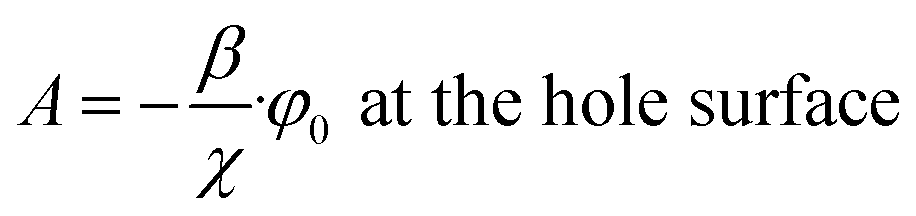
At the hole surface (“lower” solution reservoir)
| c = c0 | (12) |
| P = 0 | (13) |
| φ = φ0 | (14) |
At the opposite porous-medium surface (“upper” solution reservoir)
| c = c0 | (15) |
| P = 0 | (16) |
| φ = 0 | (17) |
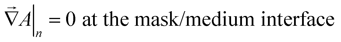
At the mask/porous-medium interface (“lower” side) we use the conditions of hydraulic impermeability of the mask
 | (18) |
 | (19) |
 | (20) |
In view of the system symmetry, at the external cell boundary we set equal to zero the normal derivatives of all the sought-after quantities, namely, the electrostatic potential, hydrostatic pressure and salt concentration. The geometry of this boundary depends on the shape and location of the holes. In this study we consider square lattices of circular holes. Accordingly, the external cell boundary is the surface of a box with a square cross-section as shown in Fig. 2.
Solution procedure
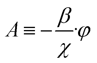
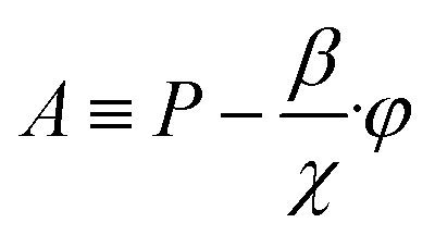 | (21) |
The volume flow is proportional to the negative gradient of this function. Due to the volume conservation, it satisfies the Laplace equation. A separate set of necessary and sufficient boundary conditions can be formulated for this problem too,
 | (22) |
| A = 0 at the back (upper) medium surface | (23) |
 | (24) |
Remarkably, this is a linear problem, so both the effective pressure and volume flow are just proportional to the applied voltage, φ0. Moreover, the solution of the hydraulic problem is not dependent on the distribution of salt concentration. It also does not explicitly depend on the distribution of the electrostatic potential (although this has an indirect impact via the effective pressure). Therefore, the hydraulic problem can be solved separately. Due to the linearity in the applied voltage, for a given system geometry this has to be done only once. After that, the electrochemical problem should be solved with a given flow distribution. This is a non-linear problem, which gives rise to non-linear current–voltage characteristics and ultimately to the non-linear dependence of the EO rate on current density.
The values of some parameters were fixed and they are listed in Table 1. The selected value for the zeta-potential (−30 mV) is typical for polymeric surfaces in (1:1) electrolyte solutions of moderate concentrations.18 The diffusion coefficient is that of KCl. The concentration of 30 mM is typical for human “external physiological fluids” (the application of active moisture removal). The hydraulic permeability of the porous medium was calculated by using the Hagen–Poiseuille relationship for straight cylindrical capillaries.
| Parameter | Value |
|---|---|
| Porous-layer thickness, L | 100 μm |
| Porous-layer pore radius | 100 nm |
| Active porosity, γ | 0.5 |
| Solution viscosity, η | 0.001 Pa s |
| Relative dielectric permittivity, ε | 80 |
| Zeta potential, ζ | −0.03 V |
| Diffusion coefficient, D | 2 × 10⁻⁹ m2 s−1 |
| Temperature, T | 298 K |
| Outside concentration, c0 | 30 mM |
Within the scope of our simplified problem formulation, the impact of some of these parameters (salt concentration, salt diffusion coefficient, porous-medium active porosity and pore size, and fluid viscosity) is rather trivial because their variation leads only to a rescaling of the current density or hydrostatic-pressure magnitude. The effect of other parameters (porous-medium thickness and zeta-potential) is less trivial and deserves a more detailed study. The hole shape and location can also have some non-trivial effects. However, the purpose of this communication is to demonstrate the principal features of the system. A more complete parametric study will be published elsewhere.
Results and discussion
Hydraulic problem
 | (25) |
| A = 0 | (26) |
Eqn (10) and (22)–(24) are formally equivalent to the problem of the distribution of electrostatic potential around a conducting infinitely thin charged circular disk in a vacuum. Instead of the semi-infinite space, we should consider an infinite space so that the condition of eqn (24) follows from the symmetry with respect to the plane of the disk. The solution of such an electrostatic problem can be found in textbooks (see, for example, ref. 19). Being proportional to the normal derivative of the electrostatic potential, the surface charge density in the electrostatic problem is analogous to the normal derivative of the effective pressure in the hydraulic problem. The electrostatic potential itself is analogous to the effective pressure.
With this analogy in mind, we can write down this expression for the distribution of effective pressure
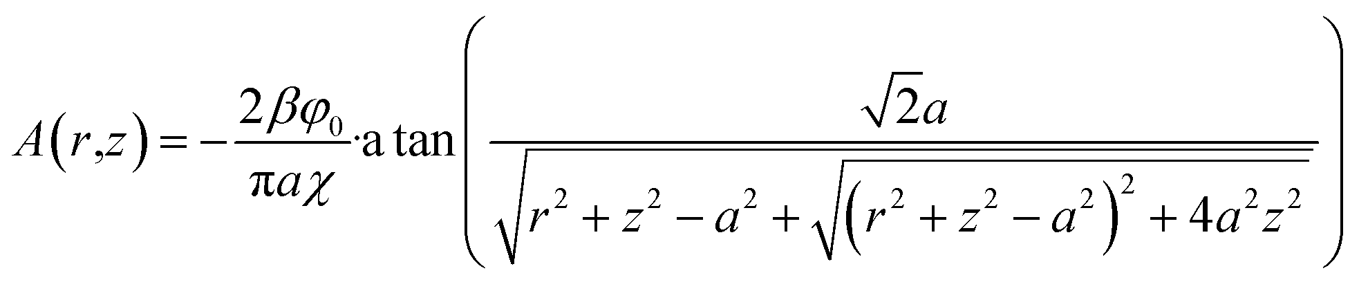 | (27) |
 | (28) |
 | (29) |
| Q = −4β·a·φ0 | (30) |
Remarkably, this volumetric flow is proportional to the hole radius and not to its area as one might expect.
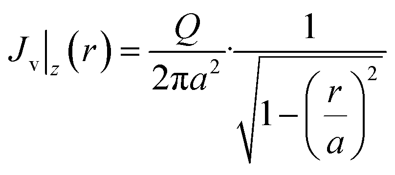
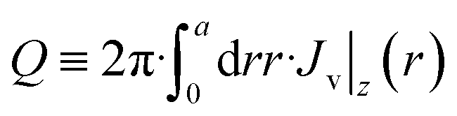
Now, we should take into account that there are actually other holes, but we consider the volume transfer through them as independent from each other (and, thus, the total flux is just the superposition of flows through single holes). One can define a per-hole surface area, S, and consider the case of no mask as a reference. In this latter case, the distribution of electrostatic potential in the porous medium is 1D and linear, so for the EO volumetric flow through the surface area of S we obtain
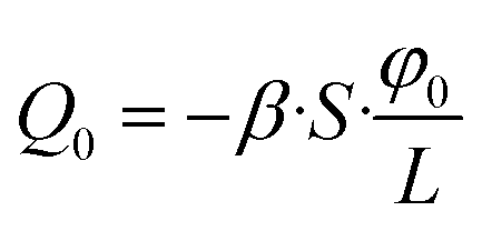 | (31) |
 | (32) |
Fig. 3 shows the shielding factor vs. the hole radius for several inter-hole half-distances.
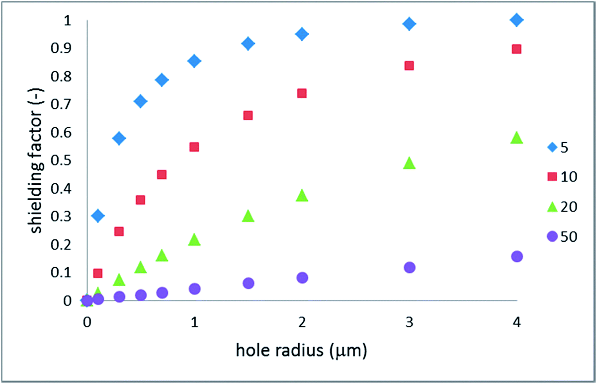 | ||
| Fig. 3 Hydraulic shielding factor vs. hole radius; the legend indicates the cell size (half-distance between the hole centers) in micrometers. | ||
Indeed, the shielding factor scales linearly with the radius when the latter is sufficiently small. As was expected, the larger the inter-hole spacing the broader the scope of applicability of non-interacting holes. Rather less expectedly, the shielding factor is close to one (weak shielding) even for relatively small surface fractions of the holes.
Fig. 4 provides additional insight into the applicability of non-interacting holes. Fig. 4a shows the shielding factor calculated numerically along with the scaling law of eqn (32). Fig. 4b shows the relative error of this approximation.
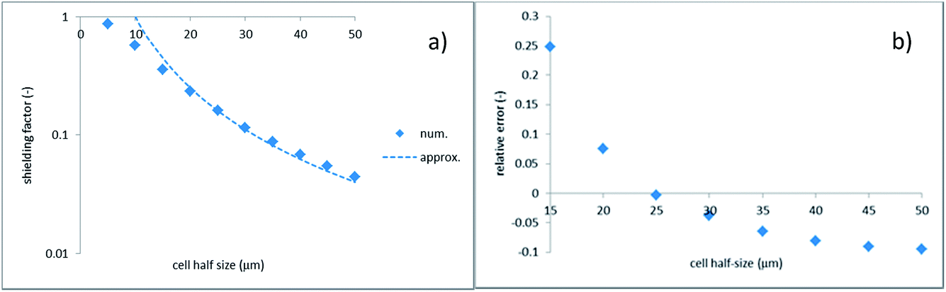 | ||
| Fig. 4 Shielding factor vs. half inter-hole spacing; hole radius is 1 μm; (a) numerics vs. scaling law of eqn (32); (b) relative error of scaling law. | ||
There is a range where the approximation works quite well (the inter-hole spacing above 40 μm). At the same time, at smaller spacing the accuracy quickly deteriorates, hence the holes interact considerably. Noticeably, this occurs already at the inter-hole spacing, which is 15 times larger than the hole diameter, for example. One can also see that the relative error does not tend to zero with increasing cell size but appears to approach a saturation value of about −10%. This is probably due to the finite thickness of the porous medium which is assumed in the numerical simulations, whereas the analytical solution considers this medium as infinitely thick. There is also a change of sign of the relative error. A positive error means that the approximation overestimates the flow. At smaller inter-hole spacings, the per-hole flow is reduced due to the inter-hole interaction (see below). At larger spacings, the dominant factor is the finite porous-medium thickness, which makes the flow somewhat larger compared to the analytical solution.
Eqn (27) shows that at distances exceeding the hole size, the effective pressure is distributed in an approximately semi-spherical way. In the electrostatic analogy, the effective pressure is analogous to the electrostatic potential of a charged disk. When sufficiently far away from it, the potential distribution approaches that of a point-like source. The electrostatic analogy also reveals that the holes behave as non-interacting as long as they can be considered as point-like (i.e., the inter-hole spacing is much larger than the hole size). Indeed, the electrostatic potentials of point-like sources just superimpose. Interactions between the holes can also be understood in electrostatic terms. If charged conducting disks (being at the same electrostatic potential) approach each other, the charges on them redistribute. This gives rise to some reduction of integral charges (analogous to the per-hole volumetric flows). Besides, there is a redistribution of charge density (analogous to the local fluid velocity normal to the hole surface). In electrostatic terms, this results in the appearance of multipole moments. For the square-lattice hole geometry considered in this study, the dipole moment is zero due to the symmetry. The first non-zero moment is quadrupole.
The analysis of the shielding factor is important because it quantifies to what extent the EO flow is reduced due to the impermeable mask. This reduction is superimposed with the increase in the voltage drop (at a given current density) due to the concentration polarization.
Electrochemical problem
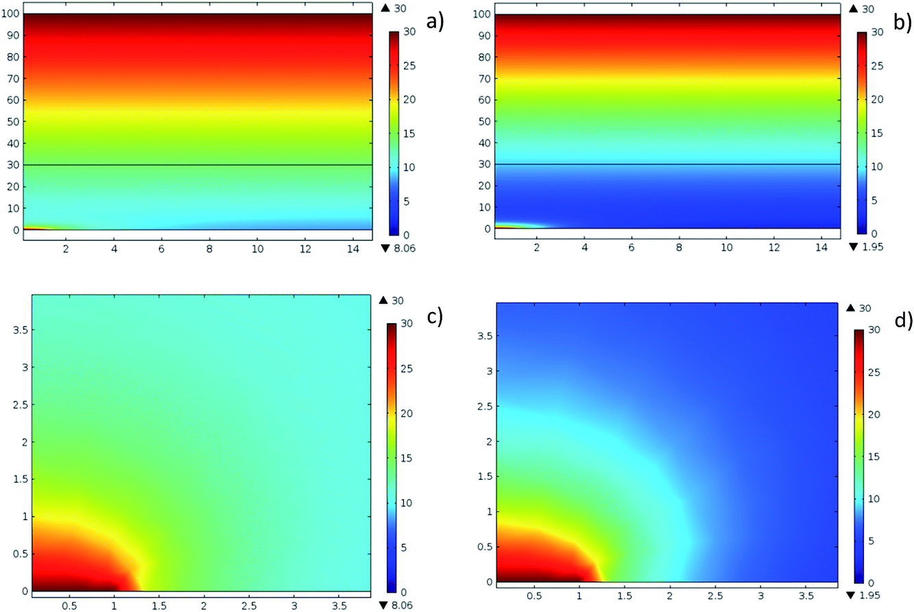 | ||
| Fig. 5 Salt-concentration distributions in the vertical plane passing through the hole center: hole radius 1 mμ, cell half-size 15 μm; in the upper maps (a, b) the scales along the vertical and horizontal axes are different; the lower maps (c, d) show the magnified vicinity of the hole with the same scaling along both axes. The hole center is in the lower left corner. (a, c) φ0 = 93 mV; (b, d) φ0 = 200 mV. | ||
These color maps reveal several important features. Firstly, at distances (in the vertical direction) exceeding the inter-hole spacing, the concentration distribution is perfectly homogeneous in the horizontal plane. Of course, color maps do not really provide quantitative insight but below we will support this statement with conventional graphs. Secondly, at intermediate distances from the hole, the concentration-distribution field is quasi-semi-spherical. Very close to the hole, the distribution is flattened due to the constant concentration set at the hole surface. Both these features are similar to the distribution of effective pressure in the hydraulic problem. Thirdly, with increasing voltage, the 1D concentration distribution in the vertical direction becomes more non-linear.
Fig. 6 shows concentration profiles along the horizontal axis (calculated where the cutline passes through the hole center).
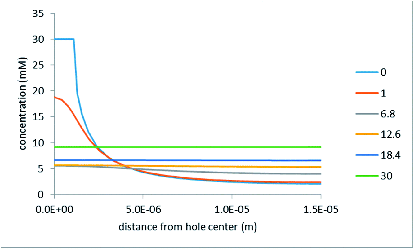 | ||
| Fig. 6 Salt-concentration profiles in the horizontal direction at various distances (in μm) from the mask/porous-medium interface as indicated in the legend: hole radius 1 μm, inter-hole spacing 30 μm, voltage drop 200 mV. | ||
The inter-hole spacing in this simulation was 30 μm. Nonetheless, one can see that, even at a distance of as little as 6.8 μm from the mask/porous-medium interface, the concentration varies in the horizontal direction by only about 25%. At a distance of 12.6 μm (still more than 2 times smaller than the inter-hole spacing) the concentration remains practically constant. Notably, the voltage drop in the simulations shown in Fig. 6 was assumed to be quite high (200 mV). At lower voltages, the concentration distribution in the horizontal direction is even more homogeneous (at some distance from the interface). At the same time, very close to the interface, the concentration distribution is strongly inhomogeneous. The same is characteristic of the distributions of the electrostatic potential and effective pressure.
Fig. 7 illustrates the non-linearity of the concentration profiles in the vertical direction.
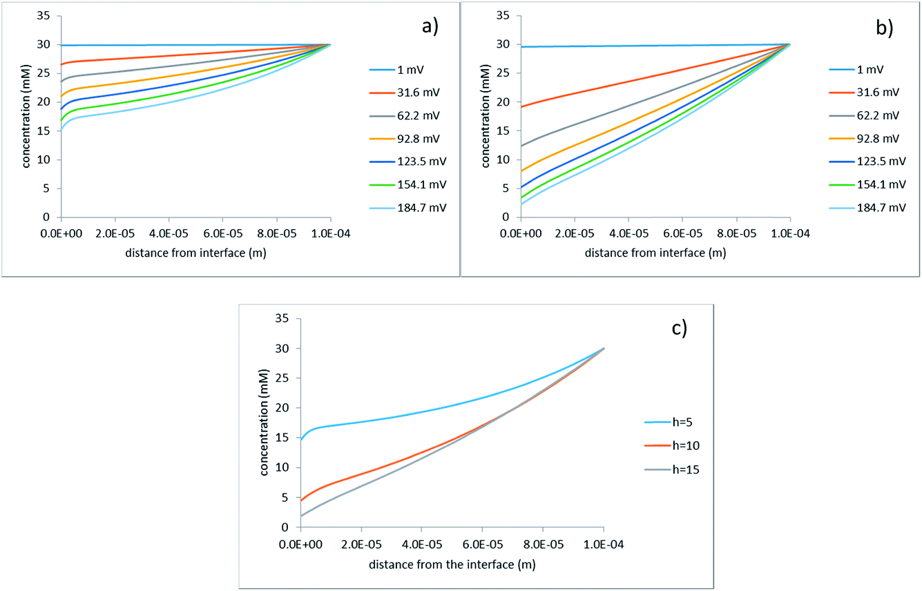 | ||
| Fig. 7 Concentration profiles along the z-axis at the upper right cell corner (see Fig. 2); (a) h = 5 μm; (b) h = 15 μm; the legends indicate the applied voltage; (c) φ0 = 200 mV, the legend indicates the half-distance between the hole centers in micrometers. | ||
Indeed, with increasing voltage the profiles become ever more concave. This is more pronounced for the smaller inter-hole spacings because the non-linearity is caused by the volume flow, which is larger in this case. This is additionally highlighted by Fig. 7c, which compares several inter-hole spacings at the same voltage. Along with the changes in the extent of non-linearity, one can see that, as is expected, the overall reduction in the concentration is stronger at larger inter-hole spacings.
Fig. 7 shows the concentration profiles calculated for the z-cutline, which is the most distant from the hole center. There, the concentration reduction is most pronounced. For comparison, Fig. 8 shows concentration profiles for a z-cutline passing through the hole edge.
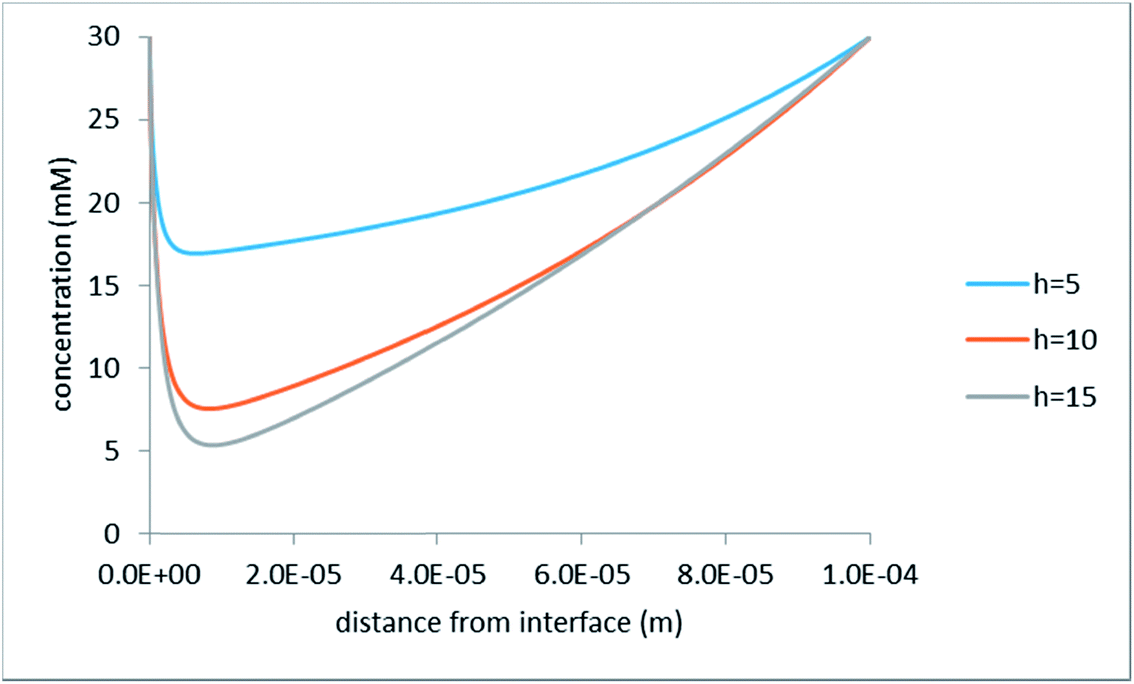 | ||
| Fig. 8 Concentration distribution along the z-axis at the hole edge; φ0 = 200 mV; the legend indicates half-distance between the hole centers in micrometers. | ||
As discussed above (see the section on the hydraulic problem), here the rate of vertical volume inflow is the largest. One can see that despite this, the concentration drops abruptly (probably due to the diffusor nature of the flow in this case), passes through a minimum, and after that crosses over to the largely 1D behavior typical at larger distances from the interface (this can be clearly seen from a comparison with Fig. 7c).
In the context of ACEO, we are also interested in negative voltages because ultimately, we need to obtain the net EO flow over the period of AC. In this steady-state analysis, we imply that the frequency of AC is sufficiently low for the system to always be in a quasi-steady state. The net EO flow over the AC period is then the algebraic sum of the volume flows occurring at current densities of the same magnitude but with opposite signs. Fig. 9 shows the concentration profiles calculated for a set of negative voltages.
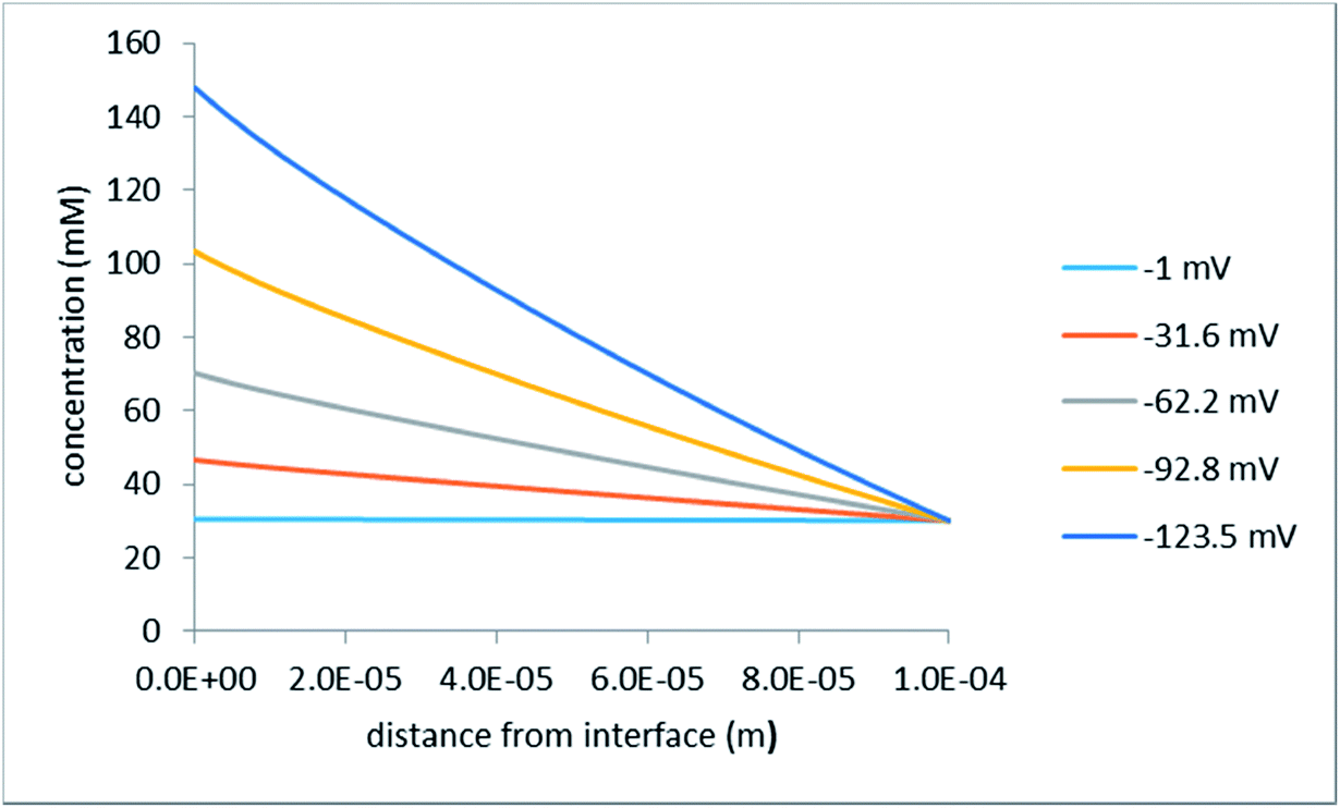 | ||
| Fig. 9 Concentration distribution along the z-axis at the upper right cell corner (see Fig. 2); the legend indicates the applied voltages; the half-distance between the hole centers is 15 μm. | ||
As is expected, in this case the concentration at the interface increases, which becomes ever more pronounced with growing voltage. This increase in concentration gives rise to larger current densities and super-linear current–voltage characteristics as discussed below.
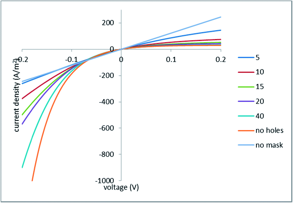 | ||
| Fig. 10 Current–voltage characteristics; the legend indicates the half-spacing between the holes (in micrometers); the hole radius is 1 μm. | ||
For the no mask example, the current–voltage characteristics is just linear
 | (33) |
For the no holes (continuous mask) example, one can obtain this relationship
 | (34) |
This case can be solved in this simple way because we neglect the ohmic voltage drop on the ion-exchange layer (otherwise one would obtain a transcendental equation for the current density).
Remarkably, the initial slope of the current–voltage characteristics for the no holes case is two times smaller than the slope of the globally linear characteristics for the no mask case. This occurs because (in our idealized system with an ideally perm-selective and conducting mask) exactly 50% of the applied voltage arises on the mask as concentration potential.
Fig. 10 shows that at positive voltages all the curves calculated for the perforated masks are confined between those two limiting cases. At negative voltages, the situation is somewhat more complex. When the voltage is low, the picture is dominated by the concentration potential arising on the mask, which (similarly to the positive voltages) has the same sign as the applied voltage. As a result, all the curves calculated for the perforated masks (including the limiting case of no holes) run above the limiting case of no mask (that is, the absolute values of current density are smaller). At larger voltages, a decrease in the ohmic resistance of the porous medium, due to the increase in the concentration, takes over, and the “masked” cases exhibit larger absolute values of current density.
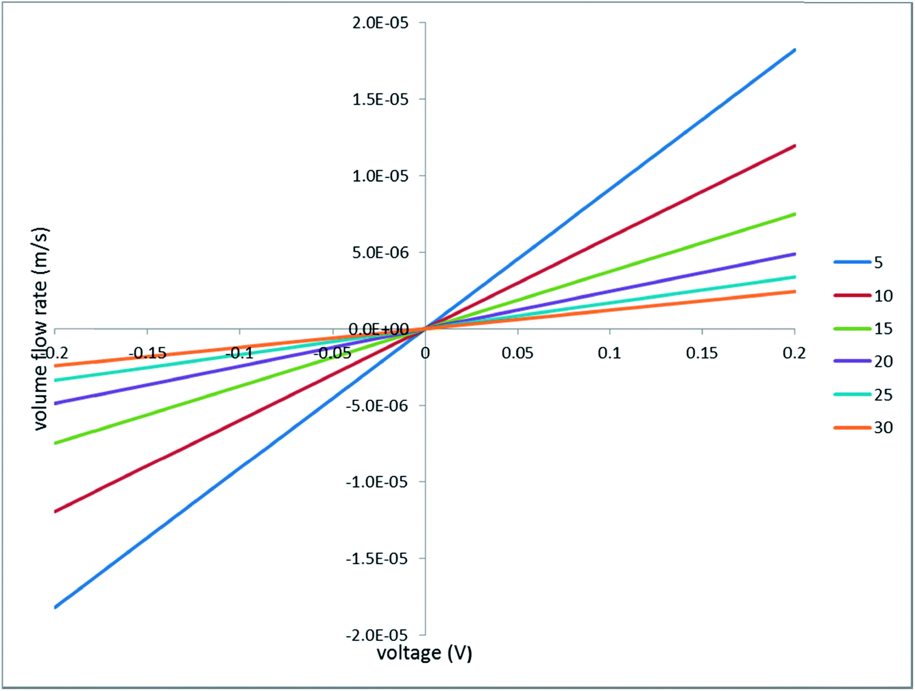 | ||
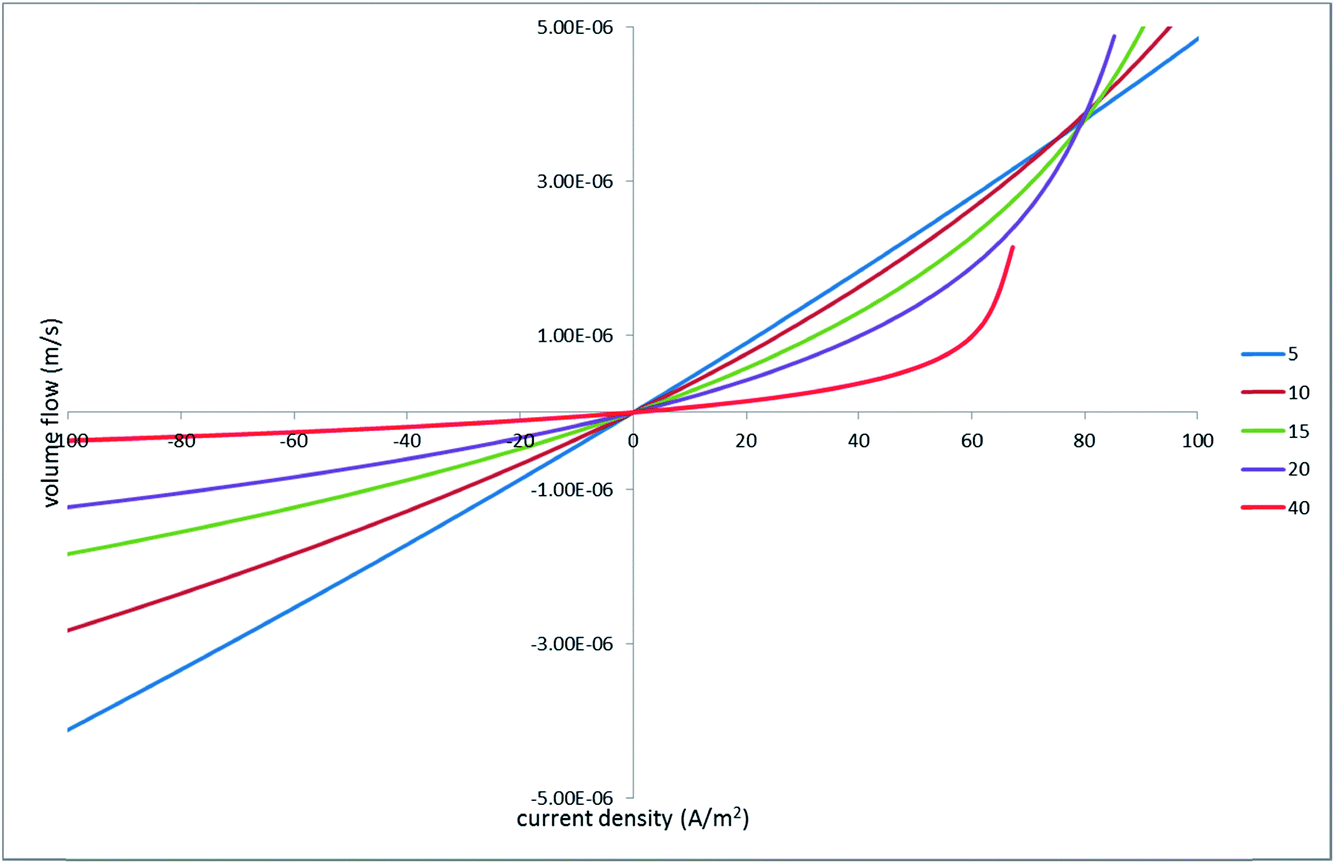
| Fig. 11 Volume flux vs. applied voltage; the legend indicates the half-distance between the hole centers in micrometers. | ||
 | ||
| Fig. 12 Volume flux vs. current density; the legend indicates the half-distances between the hole centers in micrometers. | ||
As is expected, increasing the inter-hole spacing makes the initial slope smaller (due to the stronger hydraulic shielding). However, it also makes the current–voltage characteristics more sub-linear (at positive voltages). In other words, the voltage needed to sustain a given current density is larger for more distant holes. According to the linear hydraulic problem, larger voltages produce proportionally larger volume flows. As a result, initially smaller flows increase dramatically within a certain current–density range so, at still larger currents, the flow rates at larger inter-hole spacings exceed the rates at smaller spacings.
This feature is even more pronounced in terms of the net volume flow under ACEO conditions (see Fig. 13), which is defined as the sum of flows occurring at currents of the same magnitude but in opposite directions. In this case, the flows within the linear parts of the flow–current characteristics (at both voltage signs) cancel out and only the non-linear parts contribute.
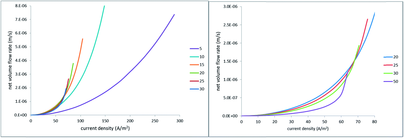 | ||
| Fig. 13 Net EO flow rate vs. absolute value of current density; the legends indicate the half-distance between the hole centers in micrometers. | ||
Cycling current (rather than voltage) is relevant in view of its possible use in capacitive electrodes where the transferred charge must be equal to zero over the AC period. However, one should keep in mind that sustaining sufficiently high current densities at larger inter-hole spacings may require much too large voltages, that can give rise to undesired faradaic reactions at the electrodes. Actually, in all of the simulations shown in Fig. 13, the voltage-drop magnitude was limited by 300 mV. This is why the curves calculated for larger inter-hole spacings end at lower current densities.
Conclusions
We have explored theoretically a new configuration exhibiting non-linear and asymmetric electroosmosis due to ionic concentration polarization. This is achieved in a layered system where a (nano)porous medium is sandwiched (on one side) with a perforated ion-exchange membrane. The purpose of the perforations is to enable noticeable volume flow through the dense ion-exchange layer, which otherwise is almost hydraulically impermeable. The function of the ion-exchange layer itself is to produce current-induced concentration polarization up to rather high salinities.The problem has been solved numerically for a model system with a square lattice of circular holes in the ion-exchange mask. For simplicity, the finite thickness of the mask was neglected and it was assumed to be ideally perm-selective in electrochemical terms. This analysis has confirmed that electroosmosis in such systems can be pronouncedly non-linear and asymmetric. The asymmetric EO gives rise to net EO flows over the period of AC when the current density is periodically cycled. We have also shown that the non-linearity and asymmetry get stronger with increasing inter-hole spacing and decreasing hole size. At the same time, making the holes more distant and smaller in size renders the EO flow smaller at lower current-densities. However, at larger currents it becomes more super-linear and this ultimately over-compensates the initially weaker flow. Notably, this occurs at larger voltage drops. In view of the low frequencies probably required for the concentration polarization to develop (and the EO asymmetry to occur in full), excessive voltages may lead to undesired electrode reactions. Therefore, in the context of practical applications, further analysis should include the electrodes (in view of the possible electrode reactions but also of the voltage drop on them). Further analysis also has to consider genuine non-stationary AC conditions. Nonetheless, even this simple steady-state analysis provides some initial guidance for the design of high-productivity and inexpensive AC electroosmotic pumps.
References
- X. Wang, C. Cheng, S. Wang and S. Liu, Microfluid. Nanofluid., 2009, 6, 145–162 CrossRef CAS PubMed.
- T. Eidsnes and O. Ellingsen, WO 1999000166 A1, Consensus As, 1998.
- http://www.osmotex.ch/en/membrane/ .
- J. Wu, J. Appl. Phys., 2008, 103, 24907 CrossRef.
- M. S. Yoon, B. J. Kim and H. J. Sung, Int. J. Heat Fluid Flow, 2008, 29, 269–280 CrossRef CAS.
- P. García-Sánchez and A. Ramos, Microfluid. Nanofluid., 2008, 5, 307–312 CrossRef.
- M. Bazant and T. Squires, Phys. Rev. Lett., 2004, 92, 66101 CrossRef PubMed.
- C.-T. Kuo and C.-H. Liu, Lab Chip, 2008, 8, 725 RSC.
- P. Cervenka, J. Hrdlicka, M. Pribyl and D. Snita, IEEE Trans. Ind. Appl., 2010, 46, 1679–1691 CrossRef.
- J. Hrdlicka, P. Cervenka, M. Pribyl and D. Snita, J. Appl. Electrochem., 2010, 40, 967–980 CrossRef CAS.
- T. A. Zangle, A. Mani and J. G. Santiago, Chem. Soc. Rev., 2010, 39, 1014–1035 RSC.
- A. R. Kneller, D. G. Haywood and S. C. Jacobson, Anal. Chem., 2016, 88, 6390–6394 CrossRef CAS PubMed.
- P. Jin, H. Mukaibo, L. P. Horne, G. W. Bishop and C. R. Martin, J. Am. Chem. Soc., 2010, 132, 2118–2119 CrossRef CAS PubMed.
- G. W. Bishop, M. M. Lopez, P. Ramiah Rajasekaran, X. Wu and C. R. Martin, J. Phys. Chem. C, 2015, 119, 16633–16638 CAS.
- X. Wu, P. Ramiah Rajasekaran and C. R. Martin, ACS Nano, 2016, 10, 4637–4643 CrossRef CAS PubMed.
- A. Yaroshchuk, Microfluid. Nanofluid., 2012, 12, 615–624 CrossRef.
- T. Xu and C. Huang, AIChE J., 2008, 54, 3147–3159 CrossRef CAS.
- R. J. Hunter, Zeta potential in colloid science: principles and applications, Academic Press, 1981, p. 386 Search PubMed.
- L. D. Landau and E. M. Lifshits, Electrodynamics of Continuous Media, Oxford University Press, 2nd edn, 1984 Search PubMed.
| This journal is © The Royal Society of Chemistry 2017 |