 Open Access Article
 This Open Access Article is licensed under a
 Creative Commons Attribution 3.0 Unported Licence
Charge-transfer dynamics at the dye–semiconductor interface of photocathodes for solar energy applications†
Fiona A.
Black
a,
Christopher J.
Wood
b,
Simbarashe
Ngwerume
b,
Gareth H.
Summers
a,
Ian P.
Clark
d,
Michael
Towrie
d,
Jason E.
Camp
*bc and
Elizabeth A.
Gibson
*ab
aSchool of Chemistry, Newcastle University, Newcastle Upon Tyne, NE1 7RU, UK. E-mail: elizabeth.gibson@newcastle.ac.uk
bSchool of Chemistry, The University of Nottingham, University Park, Nottingham, NG7 2RD, UK
cDepartment of Chemical Sciences, University of Huddersfield, Queensgate, Huddersfield, HD1 3DH, UK
dCentral Laser Facility, Research Complex at Harwell, Science and Technology Facilities Council, Rutherford Appleton Laboratory, Harwell Campus, Didcot, Oxfordshire OX11 0QX, UK
First published on 4th January 2017
Abstract
This article describes a comparison between the photophysical properties of two charge-transfer dyes adsorbed onto NiO via two different binding moieties. Transient spectroscopy measurements suggest that the structure of the anchoring group affects both the rate of charge recombination between the dye and NiO surface and the rate of dye regeneration by an iodide/triiodide redox couple. This is consistent with the performance of the dyes in p-type dye sensitised solar cells. A key finding was that the recombination rate differed in the presence of the redox couple. These results have important implications on the study of electron transfer at dye|semiconductor interfaces for solar energy applications.
Introduction
There has been extensive research into the anchoring of dye molecules such as dyes and catalysts to the surface of TiO2 to facilitate effective photoinduced electron transfer to or from the conduction band of the semiconductor.1–5 However, there have been few studies regarding the binding of molecules to the surface of p-type semiconductors such as NiO. NiO has shown potential in applications such as tandem dye-sensitised solar cells6,7 and photocatalytic water splitting devices.8 Both the TiO2 and NiO systems operate under similar principles. Under illumination, the sensitiser absorbs a photon and is promoted to an excited state, allowing injection of a hole to NiO, and the formation of a dye˙−|NiO+ charge-separated state. The reduced dye then transfers charge to either a redox couple or a catalyst to regenerate the dye in its ground state. Despite their potential to increase the efficiency of photoelectrochemical cells, the performance of these photocathodes lags behind that of TiO2-based photoanodes.9,10 To date, design approaches that have been successfully applied to TiO2 sensitizers have been adopted for NiO. However, as NiO has a very different crystal structure and surface chemistry from TiO2, it is not obvious that anchoring groups that are optimal for one material are suitable for another. It may be necessary to find a new binding moiety for NiO if the efficiency of p-type photoelectrochemical systems are to be improved.In general, research in this field has shown that donor–acceptor structures promote efficient charge separation at the dye|NiO interface.11–14 The highest quantum efficiencies have been attained with dyes that incorporate a triphenylamine donor group functionalised with either one or two carboxylic acid groups, which bind to the metal oxide surface.12,15–17 For example, we achieved a high current (8.21 mA cm−1) using a triphenylamine donor and two cationic acceptor units (CAD3 dye, Fig. 1).7 Derivatives, CAD1 and CAD2, which contain one acceptor group, exhibited a higher loading on the NiO surface and CAD2, which contains an extra 2,4-hexyloxy-phenyl group appended to the triphenylamine, attained a longer hole lifetime than CAD3.18 However, CAD1 and CAD2 generated less photocurrent than CAD3. Despite the high photocurrent, the free energy difference between the valence band of the NiO and the HOMO of these dyes is >0.8 eV. Thus, a substantial amount of energy is wasted in the initial photoinduced charge-separation step. One way to reduce this energy loss is to add electron density onto the group neighbouring the anchor using aromatic heterocycles. In this study, we have developed a dicarboxypyrrole moiety as an effective binding group for NiO, and coupled it to the cationic acceptor group used previously in our best-performing dye, CAD3. To assess the success of our new anchoring unit, the electrochemical, photophysical properties of the dye in solution and absorbed onto NiO films have been investigated. The performance of CAD4 in p-DSSCs was compared with that of CAD3. The decay of the charge-separated state by recombination and dye regeneration were also compared for the two dyes using time-resolved absorption spectroscopy.
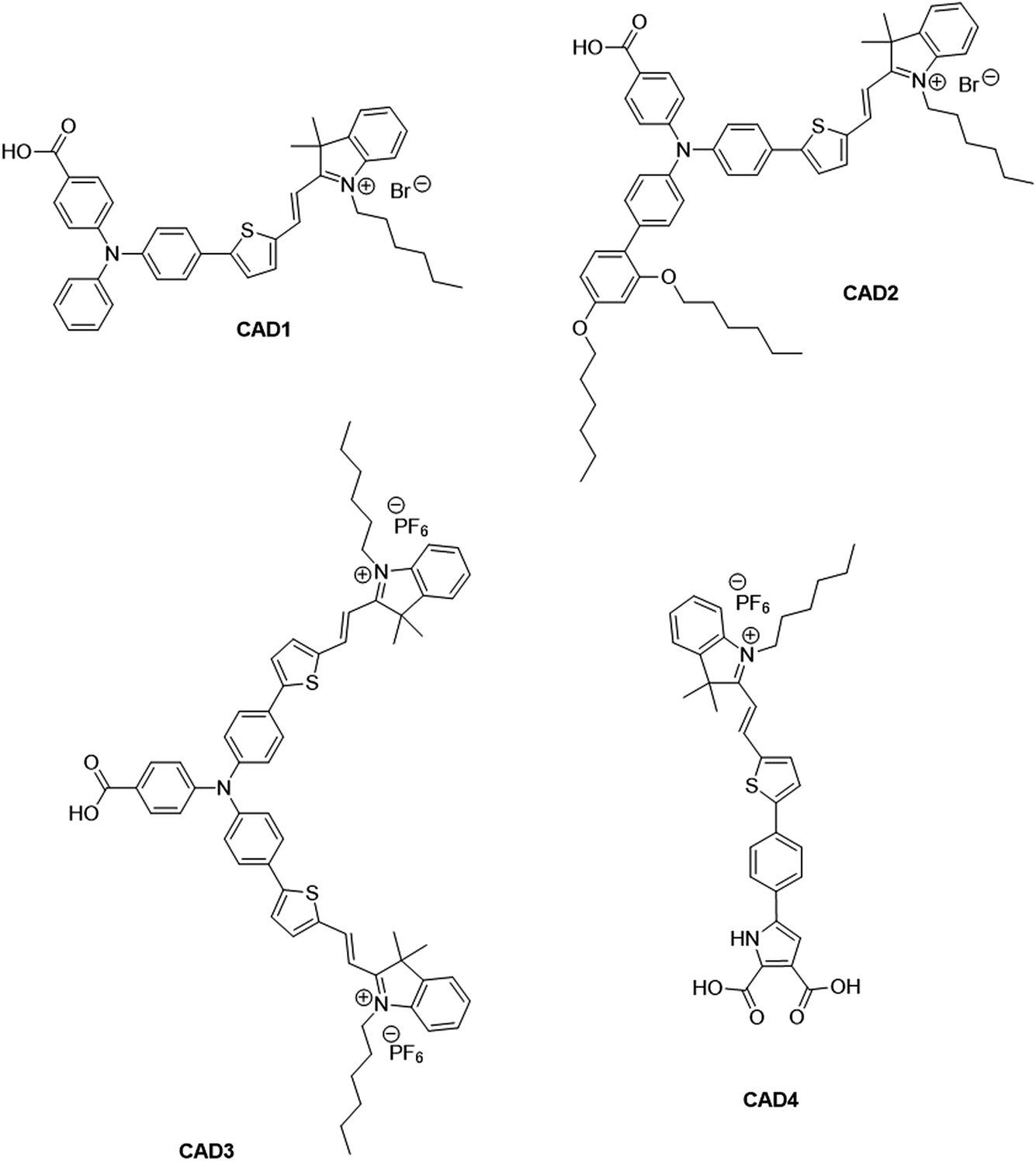 | ||
| Fig. 1 Structures of cationic acceptor dyes CAD1–4. CAD1–3 have been reported previously. Our new dye, CAD4, contains a novel heterocyclic anchoring group. | ||
Experimental section
Materials and instruments
All reagents and solvents (analytical grade) were purchased from Sigma-Aldrich or Fisher Scientific and used without further purification. Dichloromethane was dried over calcium hydride and distilled under argon and toluene was dried over sodium/benzophenone and distilled under argon prior to use. (E)-1-(4-Bromophenyl)ethanone oxime was prepared according to a literature procedure.19 Column chromatography was performed using silica gel (60 mesh) purchased from Fluka. Microwave reactions were carried out in a sealed reaction vessel in a CEM Discover SP Microwave Synthesizer and the temperature of the reaction was monitored by IR.All products were characterised by 1H NMR and 13C NMR using a Bruker 300, 400 or 700 MHz spectrometer at 25 °C; chemical shifts (δ) are reported in parts per million (ppm) from low to high field and referenced to residual non-deuterated solvent. Standard abbreviations indicating multiplicity are used as follows: s = singlet; d = doublet; t = triplet; m = multiplet, and br s = broad singlet. High resolution mass spectrometry (HRMS) was carried out on a high-throughput LC-MS system, based on a Bruker MicroTOF (Time of Flight) mass spectrometer using ElectroSpray Ionisation (ESI†). The absorption spectra were measured using an Ocean Optics USB2000 spectrometer. Ground state FTIR-spectra were recorded using a Varian Scimitar 800 FT-IR.
Dye synthesis
![[thin space (1/6-em)]](https://www.rsc.org/images/entities/char_2009.gif) :1 petrol:ethyl acetate) to afford dimethyl 2-((((E,Z)-1-(4-bromophenyl)ethylidene)amino)oxy)maleate (1, 1.31 g, 92%, E:Z-mixture, 10:1) as a colourless oil, which had data identical to that reported in the literature.19
:1 petrol:ethyl acetate) to afford dimethyl 2-((((E,Z)-1-(4-bromophenyl)ethylidene)amino)oxy)maleate (1, 1.31 g, 92%, E:Z-mixture, 10:1) as a colourless oil, which had data identical to that reported in the literature.19
(E)-Isomer: 1H NMR (CDCl3, 300 MHz): δ 7.39 (m, 4H), 5.95 (s, 1H), 3.75 (s, 3H), 3.58 (s, 3H), 2.31 (s, 3H); 13C NMR (CDCl3, 75 MHz): δ 164.6, 162.5, 158.9, 153.0, 133.3, 131.6, 128.0, 124.5, 105.8, 52.6, 51.5, 13.2.
:1 petrol:ethyl acetate) to afford dimethyl 5-(4-bromophenyl)-1H-pyrrole-2,3-dicarboxylate (2, 140 mg, 74%) as a white solid, which had data identical to that reported in the literature.19
1H NMR (CDCl3, 400 MHz): δ 9.96 (s, 1H), 7.52 (d, J = 8.8 Hz, 2H), 7.44 (d, J = 8.8 Hz, 2H), 6.89 (d, J = 3.1 Hz, 1H), 3.88 (s, 3H), 3.87 (s, 3H); 13C NMR (CDCl3, 100 MHz): δ 164.1, 160.6, 133.7, 132.2, 131.0, 126.3, 122.9, 122.2, 121.5, 110.9, 52.3, 51.9.
:MeOH gradient (0–1% MeOH)) to afford dimethyl 5-(4-(5-formylthiophen-2-yl)phenyl)-1H-pyrrole-2,3-dicarboxylate (3, 50 mg, 87%) as a yellow solid.
1H NMR (CDCl3, 400 MHz): δ 9.94 (s, 1H), 9.68 (br s, 1H), 7.79 (d, J = 4.0 Hz, 1H), 7.76 (d, J = 8.4 Hz, 2H), 7.65 (d, J = 8.4 Hz, 2H), 7.48 (d, J = 4.0 Hz, 1H), 7.03 (d, J = 3.0 Hz, 1H), 3.98 (s, 3H), 3.94 (s, 3H); 13C NMR (CDCl3, 75 MHz): δ 182.9, 164.2, 160.7, 153.2, 142.9, 137.5, 133.8, 133.0, 131.1, 127.3, 125.5, 124.5, 123.4, 121.8, 111.5, 52.5, 52.2; HRMS (ESI): m/z calcd for C19H16NO5S: 370.075, found: 370.072.
1H NMR (DMSO-d6, 300 MHz): δ 12.83 (br s, 1H), 9.91 (s, 1H), 8.04 (m, 3H), 7.83 (d, J = 9.1 Hz, 2H), 7.81 (d, J = 4.2 Hz, 1H), 7.22 (d, J = 2.8 Hz, 1H); 13C NMR (DMSO-d6, 75 MHz): δ 184.5, 169.0, 161.3, 152.5, 142.4, 139.7, 135.1, 132.2, 131.5, 127.0, 126.9, 126.8, 125.9, 119.9, 112.2; HRMS (ESI): m/z calcd for C17H10NO5S: 340.0285, found: 340.0287.
1H NMR (DMSO-d6, 700 MHz): δ 11.81 (br s, 1H), 8.71 (d, J = 15.7 Hz, 1H), 8.20 (d, J = 4.1 Hz, 1H), 8.03 (d, J = 8.5 Hz, 2H), 7.91 (d, J = 4.0 Hz, 1H), 7.90–7.85 (m, 2H), 7.81 (d, J = 8.5 Hz, 2H), 7.65–7.56 (m, 2H), 7.27 (d, J = 15.7 Hz, 1H), 7.01 (d, J = 2.5 Hz, 1H), 4.62 (t, J = 7.4 Hz, 2H), 1.84 (t, J = 7.6 Hz, 2H), 1.80 (s, 3H), 1.47–1.40 (m, 2H), 1.37–1.25 (m, 4H), 0.86 (t, J = 7.2 Hz, 3H); 13C NMR (DMSO-d6, 175 MHz): δ 184.4, 180.9, 166.1, 163.6, 154.3, 146.4, 144.0, 142.0, 141.3, 139.6, 133.5, 131.4, 131.1, 129.6, 129.4, 126.9, 126.8, 126.1, 126.0, 122.4, 115.3, 111.5, 111.20, 110.17, 52.3, 44.2, 31.3, 28.6, 26.3, 26.0, 22.7, 22.4, 22.1, 14.3; HRMS (ESI): m/z calcd for C34H35N2O4S: 567.2318, found: 567.2336. UV-Vis: λmax = 567 nm, ε = 63124 L mol−1 cm−1. IR(KBr): ν = 1707 (br), 1624 (s), 1578 (s), 1462 (s), 1425 (s), 1300 (s), 1261 (s), 1217 (s) cm−1.
Density functional theory
All theoretical studies were carried out using Gaussian g03 software on the University of Nottingham HPC (Jupiter) facility. Calculations for optimised geometry and the subsequent energies and plots of the principle molecular orbitals were performed using density functional theory (DFT) using a B3LYP hybrid functional and a 6-31G(d) basis set. Principle electronic transitions and subsequent UV-visible spectra were predicted with time dependent density functional theory (TDDFT) using the same functional and basis sets as above. These calculations were performed for the compounds in dichloromethane and acetonitrile using CPCM for the polarisable continuum model (PCM).Dye-sensitized solar cell fabrication and characterisation
The NiO precursor solution was prepared by dissolving anhydrous NiCl2 (1 g) and tri-block co-polymer F108 (poly(ethylene glycol)-block-poly(propylene glycol)-block-poly(ethylene glycol)) (1 g) in ethanol (6 g) and ultrapure Milli-Q water (5 g). p-DSCs were made by spreading the precursor solution described above onto conducting glass substrates (Pilkington TEC15, sheet resistance 15 Ω per square) using Scotch tape as a spacer (0.2 cm2 active area), followed by sintering in an oven at 450 °C for 30 min. Additional layers of precursor solution were applied and sintered to increase the film thickness. The film thickness of the undyed NiO electrodes were measured using a Bruker DektakXT stylus profileometer and averaged over 4 samples. The NiO electrodes were soaked in an acetonitrile solution of the dye (0.3 mM) for 16 h at room temperature. The dyed NiO electrode was assembled face-to-face with a platinized counter electrode (Pilkington TEC8, sheet resistance 8 Ω per square) using a 30 mm thick thermoplastic frame (Surlyn 1702, Dyesol). The electrolyte, containing LiI (1.0 M) and I2 (0.1 M) in acetonitrile, was introduced through a pre-drilled hole in the counter electrode, which was sealed afterwards.The UV-visible absorption spectra of the dyes adsorbed on NiO films were recorded using an Ocean Optics USB2000+VIS-NIR fibre-optic spectrophotometer. The concentration of dye adsorbed onto each film was calculated by the difference in the absorption spectra of the dye solution before and after immersing the film, using ε614 = 94580 M−1 cm−1 for CAD3 and ε567 = 12625 M−1 cm−1 for CAD4. Current–voltage measurements were recorded using an Ivium CompactStat under simulated sunlight from an Oriel 150 W solar simulator, giving light with an intensity of 100 mW cm−2. Incident photon-to-current conversion efficiencies were recorded using light from the solar simulator passed through a Cornerstone monochromator and calibrated against a certified reference Si photodiode. Charge extraction, hole transport times and lifetimes in the complete devices were measured using time-resolved small light modulation techniques using an Ivium CompactStat fitted with a Modulight.
Spectroelectrochemistry
Spectroelectrochemical measurements were performed on TiO2 films sensitised with CAD3 or CAD4, with a platinum wire counter electrode and an Ag/AgNO3 reference electrode. The supporting electrolyte was 0.2 M LiClO4 in MeCN. Electrolyte solutions were degassed with nitrogen prior to the measurement.Ultrafast transient absorption spectroscopy
Time-resolved spectroscopy data were recorded using time-resolved multiple probe spectroscopy (TRMPS), a brief description is provided below and full details are described in ref. 20. Briefly, two Ti:sapphire amplifiers of 10 kHz and 1 kHz were synchronized using a common 65 MHz oscillator. The 1 kHz output was used as a pump and the 10 kHz as probe, to permit a pump–probe–probe–probe… data-recording scheme. The pump laser is tuned to 532 nm by optical parametric amplification (OPA). The probe pulse was provided by a white light continuum (WLC), which was generated by focusing 800 nm into CaF2. The pump–probe time delay was controlled up to 100 μs using a combination of electronic and optical delay. Spot sizes in the sample region were ca. 150 and 50 μm for the pump and probe, respectively, with a pump energy of 20 nJ. For all measurements the pump polarization was set to the magic angle relative to the probe.
Samples were prepared by adsorbing the dye on a mesoporous NiO film deposited on a CaF2 window (Crystran). The NiO films were prepared by spraying a saturated solution of NiCl2 in acetylacetone onto the surface of the CaF2 window, which was preheated to 450 °C on a hot plate; this was then allowed to cool slowly to room temperature to give a compact film of NiO. The mesoporous layer was then deposited on top of the compact layer using the F108-templated precursor solution described below; the excess was removed by a doctor blade. The film was sintered at 450 °C for 30 min, and an additional layer of precursor solution was applied and sintered to increase the film thickness. All spectra were recorded in solution cells (Harrick Scientific Products Inc.) with CaF2 windows. This was filled either with an inert electrolyte (0.1 M LiClO4 in MeCN), or a redox electrolyte (3 mM I2 and 0.1 M LiI in MeCN). For samples prepared in dichloromethane, a 490 μm path length was used. In all experiments the cell was rastered in the two dimensions orthogonal to the direction of beam propagation to minimize localized sample decomposition. Molecular signals were verified to exhibit linear behaviour with respect to the pump intensity, indicating the kinetics reported correspond to single-photon absorption events.
Results and discussion
Synthesis of CAD4
The synthesis of CAD3 has been reported previously.7 The synthesis of CAD4 follows a modular approach. Firstly, the di-carboxylate pyrrole anchoring group 2 is formed in a two-step process from (E)-1-(4-bromophenyl)ethanone oxime (Fig. 2). Suzuki coupling of aryl bromide 2 with 5-formyl-2-thienylboronic acid afforded tricycle 3 that contained a thiophene linker group. Base-catalysed hydrolysis of esters 3 followed by condensation of aldehyde 4 with 1-hexyl-2,3,3-trimethyl-3H-indol-1-ium hexafluorophosphate gave CAD4 5. This stepwise synthesis allows for simple modifications to the structure of the linker and acceptor groups. This synthetic approach also cuts down on the total number of steps required to synthesise the dye relative to our previous work on CAD3.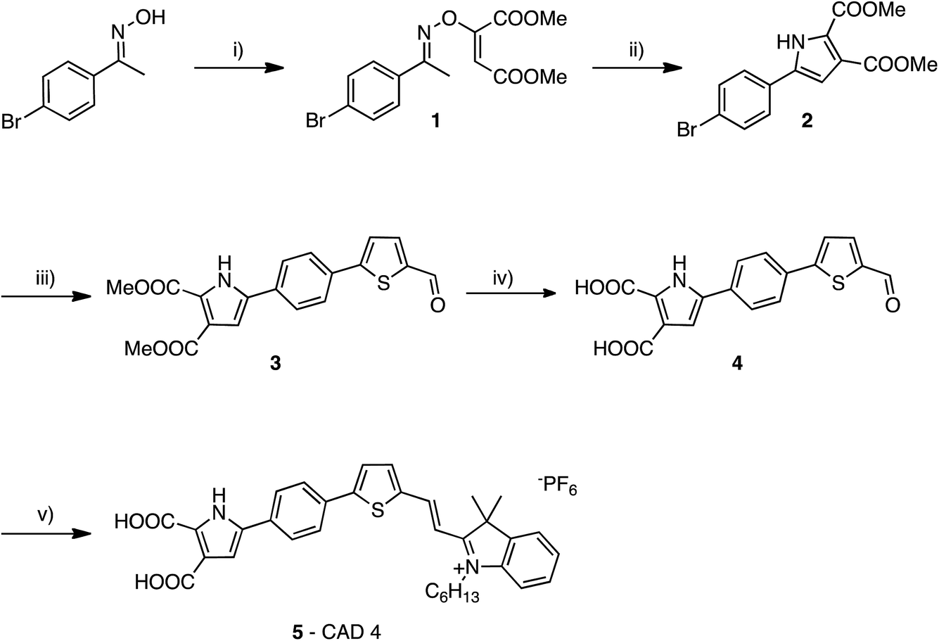 | ||
| Fig. 2 Synthesis of CAD4. (i) DABCO, dimethyl acetylenedicarboxylate, DCM, −10°C to rt, 17 h, 92%, (ii) toluene, microwave irradiation, 170 °C, 45 min, 74%, (iii) 5-formyl-2-thienylboronic acid, Pd(PPh3)2Cl2, NaCO3, H2O/DME, 90 °C, 18 h, 87%, (iv) MeOH/H2O, NaOH, reflux, 12 h, 80%, (v) 1-hexyl-2,3,3-trimethyl-3H-indol-1-ium hexafluorophosphate, piperidine, MeCN, reflux, 48 h, 42%. | ||
Optical and electrochemical properties
The absorption maxima of CAD3 and CAD4 in both CH2Cl2 and immobilised on a NiO film are provided in Table 1. CAD3 exhibits a broad absorption feature between 400 and 750 nm (see Fig. S6†). The absorption band of CAD4 is narrower and the maximum is blue-shifted relative to CAD3 (Fig. S8†). The maximum molar absorption coefficient of CAD4 is approximately half that previously reported for CAD1 and CAD2, and is seven times lower than that of CAD3.7,18 The redox potentials for CAD3 and CAD4 were determined by differential pulse voltammetry, and are also listed in Table 1. From these values, it is possible to estimate the driving force for charge separation (ΔGinj = e[EVB(NiO) − ED*/D−]) and dye regeneration (ΔGreg = e[ED/D− − E(I3−/I2˙−)]). ΔGreg = 0.23 eV for CAD4, which is similar to the previous CAD dyes, should be sufficient for dye regeneration to occur.7,18 ΔGinj = 0.99 eV for CAD4, which is larger than was calculated for the triphenylamine-based dyes CAD1–3, strongly favours hole injection to NiO.| Dye | λ abs/nm (ε/L mol−1 cm−1) | λ abs (NiO)/nm | E 0–0/eV | E (D+/D)/V vs. Fe(Cp)2+/0 | E (D/D−)/V vs. Fe(Cp)2+/0 |
|---|---|---|---|---|---|
| CAD3 | 614 (94580) |
614 | 1.78 | 0.59 | −0.99 |
| CAD4 | 532 (12625) |
528 | 1.88 | 0.89 | −0.98 |
Solar cells
NiO electrodes were constructed by sequential applications of NiO precursor solution and sintering between steps until a film thickness of 1.5 μm was obtained. The electrodes were then soaked in a solution of the dye and assembled in sandwich cells with a platinised counter electrode (see Experimental section for details). The photovoltaic performances of these p-DSCs are summarised in Table 2. The estimated loading of the CAD4 dye was almost double that estimated for CAD3. This suggests the two anchoring groups and the small footprint of CAD4 facilitate stable anchoring of the dye to the surface of NiO. This stable anchoring is supported by the loss of νC![[double bond, length as m-dash]](https://www.rsc.org/images/entities/char_e001.gif) O bands in the FTIR spectrum as CAD4 is adsorbed on NiO (Fig. S10†). The VOC obtained for both CAD3 and CAD4 was typical for p-DSCs incorporating the iodide/triiodide redox couple. The key difference between the two dyes is the photocurrent densities achieved (7.01 and 3.96 mA cm−2 for CAD3 and CAD4 respectively). We have previously reported an optimised p-DSC incorporating CAD3 that generated a photocurrent of 8.2 mA cm−2, achieved using thicker (five layer) films. The optimum number of layers when CAD4 was used was four and beyond this the VOC, and therefore the efficiency, decreased. In this study we report performances based on 4-layer films to allow CAD3 to be compared to CAD4 under the same conditions. Although lower than CAD3, CAD4 still achieved a reasonable photocurrent relative to other dyes containing only one acceptor group per molecule (CAD1 and CAD2 produced ca. 3.30 mA cm−2).7,18 It is likely that the lower photocurrent generated by CAD4 relative to CAD3 is due to the lower absorption coefficient of the dye and the narrower spectral response of the CAD4 solar cell (Fig. S15†). Nonetheless, CAD4 may be useful in co-sensitized solar cells and work is ongoing to investigate this.
O bands in the FTIR spectrum as CAD4 is adsorbed on NiO (Fig. S10†). The VOC obtained for both CAD3 and CAD4 was typical for p-DSCs incorporating the iodide/triiodide redox couple. The key difference between the two dyes is the photocurrent densities achieved (7.01 and 3.96 mA cm−2 for CAD3 and CAD4 respectively). We have previously reported an optimised p-DSC incorporating CAD3 that generated a photocurrent of 8.2 mA cm−2, achieved using thicker (five layer) films. The optimum number of layers when CAD4 was used was four and beyond this the VOC, and therefore the efficiency, decreased. In this study we report performances based on 4-layer films to allow CAD3 to be compared to CAD4 under the same conditions. Although lower than CAD3, CAD4 still achieved a reasonable photocurrent relative to other dyes containing only one acceptor group per molecule (CAD1 and CAD2 produced ca. 3.30 mA cm−2).7,18 It is likely that the lower photocurrent generated by CAD4 relative to CAD3 is due to the lower absorption coefficient of the dye and the narrower spectral response of the CAD4 solar cell (Fig. S15†). Nonetheless, CAD4 may be useful in co-sensitized solar cells and work is ongoing to investigate this.
| Dye | J SC (mA cm−2) | V OC (mV) | FF/% | η/% | Dye loading/10−6 mol cm−2 |
|---|---|---|---|---|---|
| CAD3 | 7.01 | 94 | 31.7 | 0.205 | 6.04 |
| CAD4 | 3.96 | 84 | 31.6 | 0.105 | 17.2 |
The dependence of the charge density and charge lifetime in the NiO films vs. applied voltage were recorded using charge extraction experiments on the same devices used for the current–voltage measurements. Charge lifetimes for CAD3 and CAD4 at the same extracted charge density are similar, and are both longer than for CAD1 and CAD2. There is an increase in τh at similar photovoltages for the device incorporating CAD3 relative to that of CAD4. This indicates either a shift in the valance band edge of NiO or a decrease in recombination between charges (h+) in NiO and the redox couple. This is reflected in the 10 mV difference in VOC obtained for CAD3 (94 mV) and CAD4 (84 mV) sensitised p-DSCs. There have been numerous reports of dyes decorated with sterically bulky alkyl or alkoxy units, the purpose of which is to act as a barrier between the redox couple and the NiO surface.6,18,21–23
Plots of extracted charge versus photovoltage are provided in Fig. S19 in the ESI.† Initially it would appear that the difference in structure between CAD3 and CAD4 has little or no effect on the extracted charge density over the range of voltages applied in this experiment. However, there is an almost three-fold increase in dye loading for CAD4 compared to CAD3. Our previously reported dyes CAD1 and CAD2 had very similar electronic properties, however, there was a notable difference in the extracted charge between the two dyes. Upon review it is possible to suggest that this difference arose due to the difference in dye loading onto the NiO surface, resulting from the 2,4-hexyloxypheny unit on CAD2. In the case of CAD3 and CAD4 the observed similarities between extracted charge experiments can be explained by the increased amount of CAD4 adsorbed on the NiO surface. From this it is possible to suggest that the difference in the electronic properties of the two dyes and the difference in the two anchoring groups have a significant effect on the electronic properties of the NiO surface. In the case of these two dyes this is offset by differences in the concentration of dye adsorbed onto the NiO surface. Determining the relationship between dye structure/loading and how this alters the energy of the valence band edge of the NiO film could provide valuable insight into the relative performances of dyes in p-DSCs and we will investigate this in the future.
Transient absorption spectroscopy
Ultrafast transient absorption spectroscopy was used to follow the formation and decay of excited states in solution (dye*) and adsorbed on NiO (dye˙−|NiO+) in the presence and absence of I−/I3−. Spectra at selected time delays and kinetic traces are provided in Fig. 3, with spectra at several delay times provided in the ESI.† Excitation of CAD3 dissolved in CH2Cl2 generates an excited state which absorbs between 450 and 600 nm and decays monoexponentially with τ485 = 55 ± 4 ps. The general shape is consistent with the transient spectra of similar dyes, CAD1 and CAD2.18 The lifetime lies between that of CAD1 and CAD2 and is consistent with an absence of luminescence. The transient absorption spectrum of CAD4 in CH2Cl2 features a sharp peak at 625 nm corresponding to the excited state which grows within 5 ps and decays biexponentially with τ627 = 43 ± 8 ps (50%) and 240 ± 50 ps (47%), or τav = 99 ps. The photogenerated transient, CAD4*, is red-shifted relative to the ground state bleach, in contrast to CAD3* where the transient is blue-shifted relative to its ground state bleach.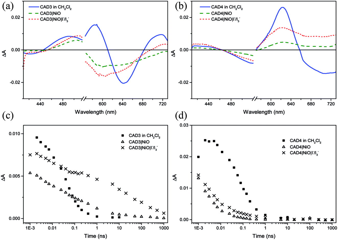 | ||
| Fig. 3 Transient absorption spectra for CAD3 (a) and CAD4 (b) at 7 ps after excitation at 532 nm in CH2Cl2 solution (blue line), absorbed on NiO film (green dashed line) and on NiO in the presence of I−/I3− (red dotted line); single kinetic traces of CAD3 (c) and CAD4 (d) in CH2Cl2 solution (squares), absorbed on NiO film in the absence (triangles) and presence of I−/I3− (crosses). | ||
Laser excitation of CAD3|NiO generates a transient with a maximum absorbance at 500 nm. We have assigned this as a CAD3˙−|NiO+ charge-separated state in agreement with our spectroelectrochemical measurements (Fig. S20†). The decay kinetics are characteristically heterogeneous (τ485 = 5 ± 1 ps (37%), 120 ± 25 ps (34%) and 4.5 ± 1.0 ns (26%)) and we have calculated an average‡τ = 94 ps. The bleach of the ground state extends to wavelengths above 525 nm and is broad and featureless, which correlates with the absorption spectrum of the ground state of CAD3 (Fig. S6†). In the presence of I−/I3−, the transient absorption spectrum of CAD3|NiO differs slightly from that of CAD3|NiO with the appearance of a peak absorbing at 700 nm. The CAD3|NiO|I−/I3− transient decays over a much longer timescale (τav = 4.0 ns) than CAD3|NiO. The peak at 700 nm overlaps with the ground state bleach so it was fit to a stretched exponential with τ720 = 16 ± 7 ps. This unexpected increase in the lifetime of the charge-separated state in the presence of the redox mediator suggests that the charge-separated state is stabilised when I3−/I− is present. I− reacts with Ni3+ at the surface of the electrode.24 This may slow the rate of charge recombination between Ni3+ and D−. Alternatively, the ions in the electrolyte may stabilise the reduced dye. However, as there is no obvious shift in the spectra there is no evidence for the latter. The transient absorption spectra of CAD4|NiO are broadened compared to CAD4* and the spectral shape resembles the reduced dye observed from our spectroelectrochemical measurements (Fig. S21†). This is consistent with the formation of the charge-separated state, CAD4˙−|NiO+. The charge-separated state decays on a much shorter timescale for CAD4˙−|NiO+ (τ640 = 2 ± 0.1 ps (79%), 35 ± 6 ps (21%)), τav = 3.6 ps, relative to CAD3˙−|NiO+. In the presence of I−/I3−, the lifetime of the CAD4|NiO charge-separated state increases slightly (τ625 = 3 ± 0.1 ps (64%), 28 ± 4 ps (25%), 0.74 ± 0.18 ns (11%)), τav = 9.6 ps, as observed for CAD3. Clearly, rapid charge-recombination should limit the efficiency of CAD4|NiO. The accelerated charge-recombination observed for CAD4˙−|NiO+ maybe a result of increased electronic coupling between the dye and the NiO when two carboxylic acids are used rather than one. Nonetheless, a reasonable solar cell performance was attained with this dye. This suggests that dye regeneration by the electrolyte is very efficient, possibly as a result of ion pairing between the positively charged acceptor moiety with I3− in the electrolyte. However, this does not explain the substantial difference between the lifetimes of CAD4˙−|NiO+ and CAD3˙−|NiO+, which one would expect to interact equally well with the redox mediator. The only explanation that we have currently is that the added steric bulk on CAD3 not only shields the acceptor from the electrode surface, but also from the electrolyte species, slowing both recombination and regeneration.
Conclusions
We have investigated the performance of a new class of pyrrole-based anchoring group for NiO photosensitizers and compared it to the triphenylamine-carboxylic acid system typically used. The very short transient lifetime for CAD4−|NiO+ compared to CAD3−|NiO+ suggests that the device performance is limited by rapid recombination. Nonetheless, the device performance was competitive with many p-type DSSCs reported previously, including CAD1 and CAD2, which, like CAD4, contain one cationic acceptor per molecule.18 The smaller dye leads to double the dye loading on the NiO film compared to CAD3, which somewhat compensates for the lower extinction coefficient and narrower absorption. In the presence of a I−/I3− redox mediator, the lifetime of the charge-separated state increased for both dyes compared to the dyed films in the presence of inert electrolyte. This shows there is some interaction between the electrolyte and dye|NiO system so highlights the importance of measuring in conditions resembling the working device. Further work will be carried out to monitor the effect of the Fermi level position on the recombination dynamics.Acknowledgements
EAG gratefully acknowledges the Royal Society for Funding a Dorothy Hodgkin Research Fellowship, a 2nd Year Research Grant. FAB thanks the EPSRC and Newcastle University for a DTA studentship. CJW thanks the EPSRC and The University of Nottingham for a DTA studentship. EAG and JEC thank the EPSRC for a Research Development Fund 2012/13 Pump Priming grant. Data supporting this publication is openly available under an ‘Open Data Commons Open Database License’. Additional metadata are available at: http://dx.doi.org/10.17634/154300-41. Please contact Newcastle Research Data Service at E-mail: rdm@ncl.ac.uk for access instructions.References
- M. Hilgendorff and V. Sundström, J. Phys. Chem. B, 1998, 102, 10505–10514 CrossRef CAS.
- J. Wiberg, T. Marinado, D. P. Hagberg, L. Sun, A. Hagfeldt and B. Albinsson, J. Phys. Chem. C, 2009, 113, 3881–3886 CAS.
- T. V. Pho, M. V. Sheridan, Z. A. Morseth, B. D. Sherman, T. J. Meyer, J. M. Papanikolas, K. S. Schanze and J. R. Reynolds, ACS Appl. Mater. Interfaces, 2016, 8, 9125–9133 CAS.
- D. F. Zigler, Z. A. Morseth, L. Wang, D. L. Ashford, M. K. Brennaman, E. M. Grumstrup, E. C. Brigham, M. K. Gish, R. J. Dillon, L. Alibabaei, G. J. Meyer, T. J. Meyer and J. M. Papanikolas, J. Am. Chem. Soc., 2016, 138, 4426–4438 CrossRef CAS PubMed.
- L. Zhang and J. M. Cole, ACS Appl. Mater. Interfaces, 2015, 7, 3427–3455 CAS.
- A. Nattestad, A. J. Mozer, M. K. R. Fischer, Y.-B. Cheng, A. Mishra, P. Bäuerle and U. Bach, Nat. Mater., 2010, 9, 31–35 CrossRef CAS PubMed.
- C. J. Wood, G. H. Summers and E. A. Gibson, Chem. Commun., 2015, 51, 3915–3918 RSC.
- F. Li, K. Fan, B. Xu, E. Gabrielsson, Q. Daniel, L. Li and L. Sun, J. Am. Chem. Soc., 2015, 137, 9153–9159 CrossRef CAS PubMed.
- F. Odobel, Y. Pellegrin, E. A. Gibson, A. Hagfeldt, A. L. Smeigh and L. Hammarström, Coord. Chem. Rev., 2012, 256, 2414–2423 CrossRef CAS.
- F. Odobel and Y. Pellegrin, J. Phys. Chem. Lett., 2013, 4, 2551–2564 CrossRef CAS.
- J.-F. Lefebvre, X.-Z. Sun, J. A. Calladine, M. W. George and E. A. Gibson, Chem. Commun., 2014, 50, 5258–5260 RSC.
- P. Qin, J. Wiberg, E. A. Gibson, M. Linder, L. Li, T. Brinck, A. Hagfeldt, B. Albinsson and L. Sun, J. Phys. Chem. C, 2010, 114, 4738–4748 CAS.
- M. Gennari, F. Légalité, L. Zhang, Y. Pellegrin, E. Blart, J. Fortage, A. M. Brown, A. Deronzier, M. N. Collomb, M. Boujtita, D. Jacquemin, L. Hammarström and F. Odobel, J. Phys. Chem. Lett., 2014, 5, 2254–2258 CrossRef CAS PubMed.
- L. Le Pleux, A. L. Smeigh, E. Gibson, Y. Pellegrin, E. Blart, G. Boschloo, A. Hagfeldt, L. Hammarström and F. Odobel, Energy Environ. Sci., 2011, 4, 2075 CAS.
- I. R. Perera, T. Daeneke, S. Makuta, Z. Yu, Y. Tachibana, A. Mishra, P. Bäuerle, C. A. Ohlin, U. Bach and L. Spiccia, Angew. Chem., 2015, 127, 3829–3833 CrossRef.
- Y. Farré, L. Zhang, Y. Pellegrin, A. Planchat, E. Blart, M. Boujtita, L. Hammarström, D. Jacquemin and F. Odobel, J. Phys. Chem. C, 2016, 120, 7923–7940 Search PubMed.
- Q.-Q. Zhang, K.-J. Jiang, J.-H. Huang, C.-W. Zhao, L.-P. Zhang, X.-P. Cui, M.-J. Su, L.-M. Yang, Y.-L. Song and X.-Q. Zhou, J. Mater. Chem. A, 2015, 3, 7695–7698 CAS.
- C. J. Wood, M. Cheng, C. A. Clark, R. Horvath, I. P. Clark, M. L. Hamilton, M. Towrie, M. W. George, L. Sun, X. Yang and E. A. Gibson, J. Phys. Chem. C, 2014, 118, 16536–16546 CAS.
- S. Ngwerume and J. E. Camp, J. Org. Chem., 2010, 75, 6271–6274 CrossRef CAS PubMed.
- G. M. Greetham, D. Sole, I. P. Clark, A. W. Parker, M. R. Pollard and M. Towrie, Rev. Sci. Instrum., 2012, 83, 103107 CrossRef CAS PubMed.
- K. A. Click, D. R. Beauchamp, Z. Huang, W. Chen and Y. Wu, J. Am. Chem. Soc., 2016, 138, 1174–1179 CrossRef CAS PubMed.
- X. Jiang, T. Marinado, E. Gabrielsson, D. P. Hagberg, L. Sun and A. Hagfeldt, J. Phys. Chem. C, 2010, 114, 2799–2805 CAS.
- S. M. Feldt, E. A. Gibson, E. Gabrielsson, L. Sun, G. Boschloo and A. Hagfeldt, J. Am. Chem. Soc., 2010, 132, 16714–16724 CrossRef CAS PubMed.
- C. J. Wood, C. A. McGregor and E. A. Gibson, ChemElectroChem, 2016 DOI:10.1002/celc.201600387.
- A. L. Smeigh, L. Le Pleux, J. Fortage, Y. Pellegrin, E. Blart, F. Odobel and L. Hammarström, Chem. Commun., 2012, 48, 678–680 RSC.
Footnotes |
| † Electronic supplementary information (ESI) available. See DOI: 10.1039/c6fd00228e |
| ‡ We have calculated average time constants from the amplitude-weighted average of logτ for each component 〈logτav〉 = (Σailog(τi))/(Σai), where ai is the fractional amplitude. This avoids bias towards slower components.18,25 |
| This journal is © The Royal Society of Chemistry 2017 |