
 Open Access Article
 This Open Access Article is licensed under a
 Creative Commons Attribution 3.0 Unported Licence
Measurement of reaction kinetics of [177Lu]Lu-DOTA-TATE using a microfluidic system†
Z.
Liu
a,
K. S.
Schaap
a,
L.
Ballemans
a,
R.
de Zanger
b,
E.
de Blois
b,
M.
Rohde
a and
E.
Oehlke
 *a
*a
aDelft University of Technology, Department Radiation Science and Technology, Mekelweg 15, 2629JB Delft, The Netherlands. E-mail: e.oehlke@tudelft.nl
bErasmus MC., Department of Radiology and Nuclear Medicine, Wytemaweg 80, 3015CN Rotterdam, The Netherlands. E-mail: r.deblois@erasmusmc.nl
First published on 5th September 2017
Abstract
Microfluidic synthesis techniques can offer improvement over batch syntheses which are currently used for radiopharmaceutical production. These improvements are, for example, better mixing of reactants, more efficient energy transfer, less radiolysis, faster reaction optimization, and overall improved reaction control. However, scale-up challenges hinder the routine clinical use, so the main advantage is currently the ability to optimize reactions rapidly and with low reactant consumption. Translating those results to clinical systems could be done based on calculations, if kinetic constants and diffusion coefficients were known. This study describes a microfluidic system with which it was possible to determine the kinetic association rate constants for the formation of [177Lu]Lu-DOTA-TATE under conditions currently used for clinical production. The kinetic rate constants showed a temperature dependence that followed the Arrhenius equation, allowing the determination of Arrhenius parameters for a Lu-DOTA conjugate (A = 1.24 ± 0.05 × 10¹⁹ M−1 s−1, EA = 109.5 ± 0.1 × 10³ J mol−1) for the first time. The required reaction time for the formation of [177Lu]Lu-DOTA-TATE (99% yield) at 80 °C was 44 s in a microfluidic channel (100 μm). Simulations done with COMSOL Multiphysics® indicated that processing clinical amounts (3 mL reaction solution) in less than 12 min is possible in a micro- or milli-fluidic system, if the diameter of the reaction channel is increased to over 500 μm. These results show that a continuous, microfluidic system can become a viable alternative to the conventional, batch-wise radiolabelling technique.
Introduction
Recent years have seen increasing interest in the application of microfluidics for the synthesis of radiopharmaceuticals. This development started in the early 2000s with 18F or 11C containing compounds,1 but studies published in the last few years also showed the advantage of microfluidics over conventional methods for metal containing radiopharmaceuticals.2–7 The reason for the success of microfluidics is that downsizing reaction vessels to the micro-scale allows for better mixing of reactants, more efficient energy transfer, less radiolysis, faster reaction optimization, and overall improved reaction control.1–8 However, limited throughput of microfluidic devices and the difficult interface between batch and continuous-flow processes used for different radiopharmaceutical preparation steps still hinder the routine clinical use.9 Up to now, the clear advantage of microfluidic systems lies in the possibility of rapid reaction optimization with very low precursor consumption as shown by Mate et al.3The remaining challenge of translating those optimization results to conventional (clinical) reaction vessels, but also to various microfluidic reactor designs without adding extensive additional experiments, could be addressed by determining kinetic constants and diffusion coefficients of the studied systems and calculating expected reaction times for the clinical applied reaction vessels. Additionally, the determined constants could be used to optimize the design of reaction vessels using computational fluid dynamics, as Haroun et al. showed recently for the microfluidic synthesis of [11C]raclopride.10
Both diffusion coefficients and kinetic constants can be obtained with microfluidic systems. So called T-sensors or H-cells have been successfully applied to determine diffusion coefficients of small molecules and proteins.11–13 And Konermann et al. showed in the late 1990s that continuous-flow methods under laminar flow conditions (as are used in microfluidics) allow not only easy and efficient determination of chemical reaction kinetics but avoid the considerable sample consumption typical for conventional continuous-flow kinetic experiments.14–17 The most common application of these systems can be found in time-resolved mass spectrometry, an analytical method used for the study of chemical kinetics or biological dynamics.18,19 A typical laminar flow setup for continuous-flow experiments consists of two capillaries through which the reactants are pumped to a T-mixer, which is again connected to the capillary in which the reaction takes place. The reaction process is measured with various analytical methods (e.g. MS,18,19 IR,20 NMR21) at different lengths of the reaction capillary, equaling different time-points of the reaction.
In this paper, we present such a microfluidic setup for the determination of kinetic association rate constants of radiopharmaceuticals. Considerations regarding the ability of our setup to determine these constants can be found in the ESI.† The reaction yields are determined by an ultra-high performance liquid chromatography (UHPLC) system, which is not connected to the microfluidic system, a fact that currently limits the studied reactions to those which do not occur at room temperature. To show the working principle of our method, we investigated the kinetic properties of the reaction of [177Lu]LuCl3 with 1,4,7,10-tetraazacyclododecane-N,N′,N′′,N′′′-tetraaceticacid[DOTA]0-Tyr3-octreotide (DOTA-TATE) under conditions applied for the clinical preparation of [177Lu]Lu-DOTA-TATE,22–24 and used the obtained results for scale-up considerations. Although the formation of [177Lu]Lu-DOTA-TATE has been studied extensively before,22,25 to the best of our knowledge no kinetic rate constants are known.
Materials and methods
Chemicals and reagents
For the (radio)synthesis of [177Lu]Lu-DOTA-TATE, [DOTA0,Tyr3]octreotate kits prepared at Erasmus MC (Rotterdam, The Netherlands) were used, which contained 0.303 mM [DOTA0,Tyr3]octreotate, 0.64 M sodium ascorbate and 0.16 M gentisic acid in 0.05 M HCl. The kits were stored at −20 °C until use. The exact concentration of [DOTA0,Tyr3]octreotate was determined by titration as described by Breeman et al.26 In short: based on an assumed concentration of DOTA-TATE, a calibration curve containing ≥4 ratios of metal ions versus DOTA-TATE in duplicate was prepared. Samples were analysed by UHPLC with a base-to-base separation of DOTA-TATE versus Lu-DOTA-TATE. At increasing amounts of Lu versus DOTA-TATE in the titration, the peak corresponding with DOTA-TATE decreased and the peak corresponding with Lu-DOTA-TATE increased.177LuCl3 (16 GBq g−1) was produced in the Hoger Onderwijs Reactor (HOR, Delft, The Netherlands). After irradiation, it was dissolved in 0.05 M HCl to a final Lu concentration of appr. 0.13 mM or 0.26 mM. For non-radioactive experiments, LuCl3 solutions of the same concentrations were prepared by diluting a 1 g L−1 Lu standard for ICP (Merck KGaA, Darmstadt, Germany) with 0.05 M HCl. All Lu solutions were analysed by Inductively Coupled Plasma – Optical Emission Spectrometry (ICP-OES, Optima 4300DV, PerkinElmer USA) to determine the exact concentrations. The scale-up radiolabelling tests were done by spiking a non-radioactive LuCl3 solution with 177LuCl3 (0.1 MBq μL−1) obtained from IDB Holland.
All chemicals applied in this study were of the highest grade, especially regarding metal purity, and were purchased at Sigma-Aldrich or Alfa Aesar if not differently indicated. Water was supplied from Milli-Q systems or Sigma-Aldrich.
Microfluidic set-up for kinetic experiments
The microfluidic set-up (Fig. 1) consisted of two 1 mL syringes (Inkjet-F, BD) that were filled with the reactant solutions and connected with capillary tubing (PEEK, 100 μm inner diameter (ID), 20 cm length) to a static mixing tee (IDEX, M-540). The static mixing tee contains a frit that enforces mixing of reactants. A third capillary with varying inner diameter (50–500 μm) and length (96–116 cm) was connected to the mixing tee. Part of this third capillary was heated (60–90 °C) and used as reaction channel. The distance between the mixing tee and the heated part of the capillary was 20 cm unless otherwise specified. The reaction capillary was heated by winding it around a self-manufactured aluminium heating block (see Fig. 1). The temperature of the heating block was checked using a precision thermometer (Greisinger GTH 175/PT, ±1 °C).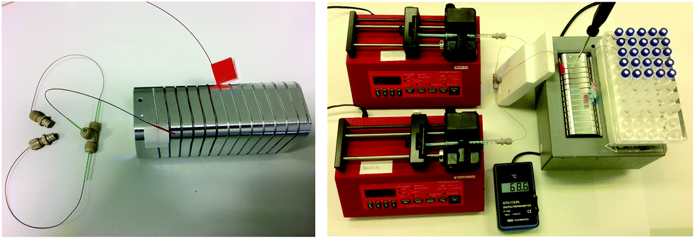 | ||
| Fig. 1 Microfluidic setup. The left picture shows capillary tubing, mixing tee and the aluminium heating block. The right picture displays the whole setup. During operation the heating block was isolated from above with a Styropor® plate. | ||
The two syringes were controlled with syringe pumps (1000 Aladdin single syringe pump) using flowrates between 1 and 160 μL min−1. The dispensing accuracy of the pumps has been specified by the supplier as ±1%, which was verified by weighing the amount of water pushed through the whole setup at different flowrates over time periods of 20 to 60 min.
Labelling procedures
All experiments were repeated at least 3 times. Before taking the samples, the microfluidic setup was flushed with the reactant solutions at the studied flowrates for at least twice the dead volume of the system. Samples of 15 μL (unless otherwise indicated) were taken at the end of the reaction capillary for analysis. All experiments besides the standard synthesis were done with non-radioactive LuCl3.![[thin space (1/6-em)]](https://www.rsc.org/images/entities/char_2009.gif) :1 (DOTA-TATE:Lu), giving a molar ratio of 2.33:1. The reaction capillary was heated to 80.1 ± 0.2 °C, and the pH of the reaction solution was 4.0–4.5. To be able to analyse the samples accurately with the radio-detector, samples of 40 μL were taken.
:1 (DOTA-TATE:Lu), giving a molar ratio of 2.33:1. The reaction capillary was heated to 80.1 ± 0.2 °C, and the pH of the reaction solution was 4.0–4.5. To be able to analyse the samples accurately with the radio-detector, samples of 40 μL were taken.
Analytical methods
The (radio)chemical yield of the labelling experiments was checked by thin layer chromatography (TLC) or ultra-performance liquid chromatography (UHPLC).For TLC, Whatman™, 3MM chromatography paper was used with 50% acetonitrile in water as solvent.27 The labelled compound had an Rf of 1, while the free radionuclide stayed at the origin.
For UHPLC an UPLC® Acquity system (H-class, UPLC column, Acquity UPLC HSS C18, 1.8 μm 2.1 × 50 mm column) equipped with an autosampler manager module at 6 °C and an Acquity PDA 2996 UV detector (Waters, Etten-Leur, The Netherlands) and Empower 3 software (Waters, The Netherlands) was used. A gradient of Methanol and 0.1% TFA was set over 3 min with a flow of 0.5 mL min−1 (see ESI†). Retention time of DOTA-TATE was ∼2.17 min, of Lu-DOTA-TATE ∼2.28 min, and ∼0.34 min and ∼0.57 min for free Lu. Radioactivity was monitored with an Osprey digital multichannel analyser connected to a NaI detector, and dedicated software (MetorX B.V, Goedereede, The Netherlands), connected to the UHPLC system.
Data analysis
The kinetic data was fitted non-linearly using a second-order kinetic model (neglecting the different protonated species of DOTA-TATE).28,29 The kinetic association rate constants (k) obtained for different temperatures were fitted non-linearly using the Arrhenius equation.30 Details about the applied formulas can be found in the ESI.†Determination of diffusion coefficients
The diffusion coefficient of Lu3+ (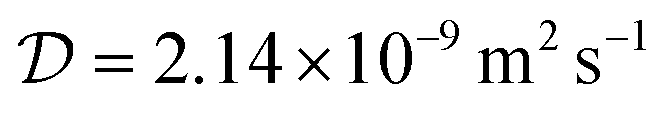 at 20 °C) was calculated based on the Stokes–Einstein equation,31 while the one of [177Lu]Lu-DOTA-TATE was determined to be 1.9 ± 0.4 × 10⁻¹⁰ m2 s−1 at 20 ± 1 °C using a method described by Miložič et al.11 (for details see ESI†). The diffusion coefficient of DOTA-TATE was approximated to be the same as the one for [177Lu]Lu-DOTA-TATE. All diffusion coefficients were adjusted to the required temperatures by using the Stokes–Einstein equation.31
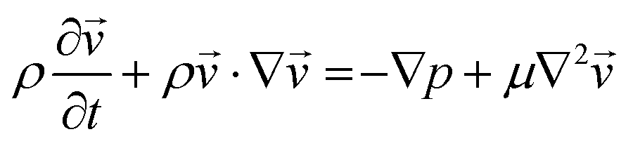
Computational modelling
 | (1) |
 | (2) |
 is the velocity (m s−1), p is the pressure (Pa), ρ is the density of the fluid (kg m−3) and μ is the dynamic viscosity of the fluid (Pa s).
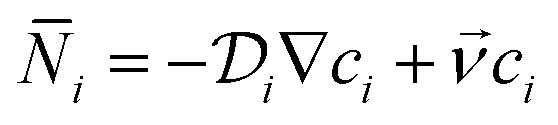
The convection–diffusion-reaction equation governs the transport of chemical species:31
 | (3) |
 is the diffusion coefficient of the chemical species i (m2 s−1), and ci denotes the concentration of the chemical species i (mol m−3). Ri denotes the reaction rate of chemical species i (mol m−3 s−1). This term represents the rate of formation of the product and the rate of consumption of the reactants.
Finally, the heat transfer process is governed by eqn (4):31
 | (4) |
Two 2-dimensional models were built to simulate the microfluidic system with or without using a static mixing tee in the experiment. For simulating the behaviour of a mixing tee, the model assumed that the reactants are fully mixed at the beginning of the reaction channel.
A T-shaped model simulated the behaviour of applying a normal tee to combine the streams of reactants. The model had two separate inlet streams where the lutetium solution entered through the top inlet and DOTA-TATE was present in the bottom inlet (Fig. 2). In this case, the reactants mix through diffusion as they progress along the reaction channel. The steady state Navier–Stokes equation was solved to describe the advection of the solution. The resolved velocity field was then coupled to the convection term both in the mass transport equation (eqn (3)) and in the heat transport equation (eqn (4)). The boundary conditions and parameters used in the models are listed in Tables 1 and 2.
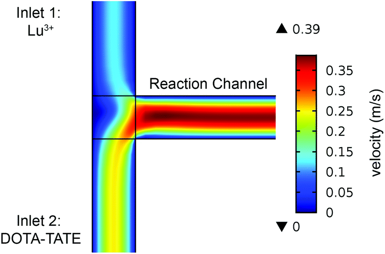 | ||
| Fig. 2 2-Dimensional model for the reaction capillary (100 μm ID, 1 m length) connected to a normal tee. The legend depicts the velocity magnitude (m s−1) of the fluid. The average velocity of the Lu3+ solution at inlet 1 is 0.08 m s−1, and the average velocity of DOTA-TATE solution at inlet 2 is 0.16 m s−1. | ||
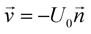
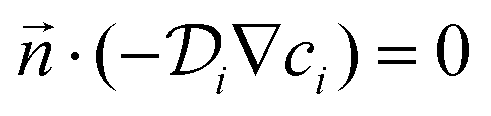
 is the normal vector, U0 is the average velocity at the inlet, p0 is the pressure at the outlet, c0,i denotes the concentration of the chemical species i at the inlet, T0 is the initial temperature of the reaction solution, and Tw is the desired reaction temperature at the heated channel wall
| Momentum | Mass transfer | Heat transfer | |
|---|---|---|---|
| Wall |
|
|
T = Tw |
|
|||
| Inlet |
|
c i = c0,i | T = T0 |
| Outlet | p = p0 |
|
If  |
| T = T0; | |||
If  |
|||
|
| Parameter | Value |
|---|---|
|
2.41 × 10⁻⁹ (at 20 °C); 7.3 × 10⁻⁹ (above 20 °C) |
|
1.9 × 10⁻¹⁰ (at 20 °C); 6.5 × 10⁻¹⁰ (above 20 °C) |
| A (M−1 s−1) | 1.24 × 10¹⁹ |
| E A (J mol−1) | 109.5 × 10³ |
| c p (J kg−1 K−1) | 4.2 × 10³ |
| λ (J m−1 s−1 K−1) | 0.6 |
| ρ (kg m−3) | 1000 |
| μ (Pa s) | 1.01 × 10⁻³ |
Results and discussion
Kinetic properties of the formation of [177Lu]Lu-DOTA-TATE at different temperatures
The kinetics of the formation of [177Lu]Lu-DOTA-TATE were determined using a microfluidic synthesis setup (total reaction times of a few minutes) together with an UHPLC system (analysis time of 3.5 min). This combination gave the opportunity to scan several reaction parameters within one day using non-radioactive LuCl3. To confirm the consistency between non-radioactive and radioactive experiments, we did experiments with lutetium solution that was spiked with [177Lu]LuCl3 obtained from IDB Holland. The yield of the radioactive experiment was measured both with the UV- (278 nm) and the radio-detector (113 and 208 keV) of the UHPLC system. Both measurements gave comparable results (see Fig. 3), therefore all further experiments were done with non-radioactive LuCl3 solution.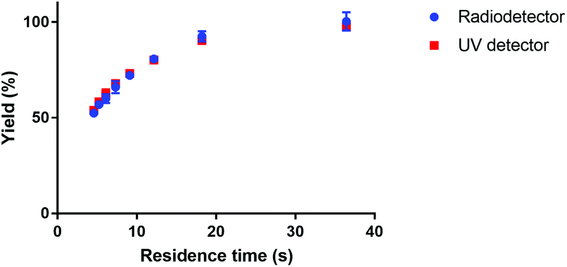 | ||
| Fig. 3 Comparison of measured reaction yield of [177Lu]Lu-DOTA-TATE for UV and radio-detection. The reaction was done in a 100 μm channel at 80 °C. | ||
Fig. 4 shows the reaction yield of Lu-DOTA-TATE as a function of residence time for different temperatures determined in a capillary with 100 μm inner diameter. Due to optimal heat and mass transfer in the microfluidic system much lower reaction times (44 s at 80 °C for 99% yield) are needed than those reported for conventional systems (8–15 min at pH 4 and 80 °C).25 The data shows also that the synthesis of Lu-DOTA-TATE is highly temperature dependent, which has been observed before for lanthanide DOTA-peptide conjugates, but was never quantified.32 The most extensive reaction studies that are available for different temperatures were done recently for Sc-DOTA and Sc-DOTA-TATE complexes at four different temperatures (25, 40, 70, and 90 °C).33
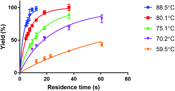 | ||
| Fig. 4 Dependence of formation of Lu-DOTA-TATE on temperature. All reactions were done in a 100 μm channel. The data points for each temperature were fitted to an equation representing second order kinetics. | ||
The measured data was fitted for each temperature to a second order rate equation. This neglects the fact that the formation of metal-DOTA complexes is a process involving several species (depending on the protonation status of the carboxylic groups on the DOTA molecule) and also reversible intermediate forms.29,34 However, the overall reaction has already previously been considered a second order reaction.29 The kinetic association rate constants that were obtained are given in Table 3.
| Temperature (°C) | k (M−1 s−1) | R 2 |
|---|---|---|
| 88.5 ± 0.2 | 1868 ± 100 | 0.7861 |
| 80.1 ± 0.2 | 902 ± 16 | 0.9793 |
| 75.1 ± 0.2 | 396 ± 15 | 0.9553 |
| 70.2 ± 0.2 | 223 ± 10 | 0.9408 |
| 59.5 ± 0.2 | 60.4 ± 2.8 | 0.8327 |
Fig. 5 shows the dependence of the kinetic association rate constants on the temperature. The Arrhenius equation was fitted to all data points (R2 = 0.991), which allowed the determination of the Arrhenius parameters for the studied reaction under the applied conditions (A = 1.24 ± 0.05 × 10¹⁹ M−1 s−1, EA = 109.5 ± 0.1 × 10³ J mol−1, an Arrhenius plot (ln(k) vs. 1/T) is shown in the ESI†). We were not able to find Arrhenius parameters for Lu-DOTA-TATE, Lu-DOTA or any similar lanthanide complexes in literature. All accessible kinetic data has been determined for temperatures around 25 °C.28,29,32,34
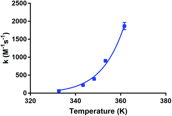 | ||
| Fig. 5 Dependence of kinetic association constants on temperature. The data points were fitted to the Arrhenius equation. | ||
The obtained parameters were further used to estimate kinetic association constants for other temperatures. Based on these constants, the residence times needed to achieve 99% radiochemical yield were calculated as a function of temperature for the conditions described in this paper (see Fig. 6). In a reaction vessel that has optimal mass and heat transfer, reaction times under one hour can be still achieved at 43 °C (t = 55 min). A slightly higher temperature, 52 °C, already allows for a reaction time of under 20 min. The estimated kinetic rate constant for 25 °C (0.813 M−1 s−1 = 4.88 × 10⁻² mM−1 min−1) is in the same order of magnitude as the one determined for Lu-DOTA previously by electrophoresis (4.54 ± 0.24 × 10⁻² mM−1 min−1 in 20 mM sodium acetate solution, pH 4.2)28 and would lead to reaction times of 12 h in a reaction vessel with optimal heat and mass transfer.
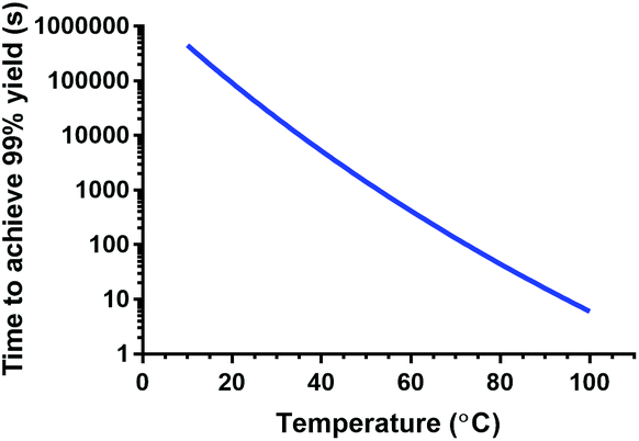 | ||
| Fig. 6 Prediction of time needed to achieve 99% yield for [177Lu]Lu-DOTA-TATE in a setup with optimal heat and mass transfer. The graph was calculated using the Arrhenius parameters obtained in this study. | ||
A point to consider when applying the here described microfluidic method for the synthesis of [177Lu]Lu-DOTA-TATE is the stability of clinical DOTA-TATE kits, which we used in this study. Previous syntheses of [177Lu]Lu-DOTA-TATE at Erasmus MC showed no detectable differences between newly prepared and old, slightly yellow, DOTA-TATE kits, and therefore these older kits are often used for first research studies. However, during our microfluidic experiments, we observed a clear trend to slower kinetics, if kit solutions were not stored at −20 °C in the dark, but had degraded over time (see Fig. 7). Reasons for this degradation could be the instability of ascorbate, which is added as radical scavenger and buffer to the solution,35 and is known to degrade at high storage temperatures, light, high pH values and in the presence of dissolved oxygen.36–38 Further investigation into the reasons for this degradation was out of scope for this study, however, it is an important point to mention, since this is the first time that degradation of kit solution has been observed to affect the synthesis of [177Lu]Lu-DOTA-TATE.
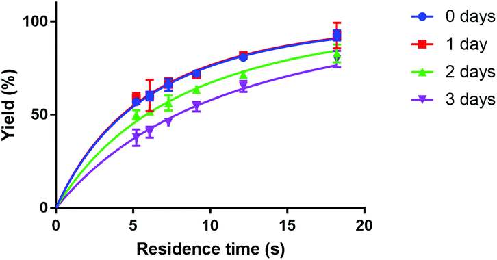 | ||
| Fig. 7 Dependence of Lu-DOTA-TATE formation on time of storage of DOTA-TATE kit at room temperature. The reaction was done in a 100 μm channel at 80 °C. | ||
Up-scaling to clinical relevant amounts
Applying a microfluidic system containing one reaction capillary with 100 μm inner diameter for the clinical synthesis of [177Lu]Lu-DOTA-TATE (currently 3 mL reaction solution at Erasmus MC), is due to the low flowrates (≤15 μL min−1 for complete conversion) certainly not feasible. However, there exist two possibilities to increase the throughput of the microfluidic system while keeping the residence time of the reaction solution the same: (I) to apply parallel systems, and (II) to increase the diameter of the reaction channel.9 While the first option mainly poses the problem of designing such a parallel system, increasing the diameter of the reaction channel requires again considerations regarding optimal heat transfer and diffusion limitations. Experimental results using capillaries with different inner diameters (up to 254 μm) showed no differences in kinetics (Fig. 8).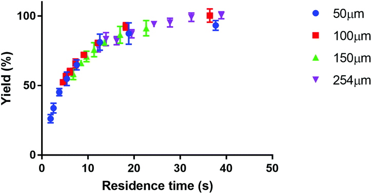 | ||
| Fig. 8 Influence of channel diameter on the reaction kinetics of [177Lu]Lu-DOTA-TATE. | ||
To determine the influence of the capillary diameter on the formation rate of [177Lu]Lu-DOTA-TATE for even higher diameters, we modelled two system options: one where the reactants were completely mixed at the beginning of the reaction channel (for example by using a static mixing tee), and one where the reactant solutions were added separately and mixing occurred solely through diffusion (Fig. 9). The computational results for the fully mixed model show that if complete mixing is achieved at the beginning of the channel, only slightly decreased yields are expected for [177Lu]Lu-DOTA-TATE when increasing the channel diameter up to 1.5 mm (Fig. 9a). Fig. 9b depicts the concentration profile of [177Lu]Lu-DOTA-TATE at the end of the reaction channel. Most of the product is formed at the walls, since the low velocities there (see Fig. 2) lead to a longer residence time of the liquid. If the solutions are, however, added separately, most of the product will be formed at the centre of the channel where LuCl3 and DOTA-TATE already had time to mix by diffusion (Fig. 9d). This leads to significantly slower reactions for larger diameters (see Fig. 9c). Nevertheless, reaction times will be with less than 100 s still smaller than those required for conventional reaction vessels (8–15 min).22,33
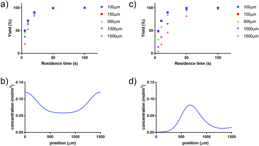 | ||
| Fig. 9 Simulation results for increasing the inner diameter of the capillary when the reactant solutions are fully mixed at the start of the reaction (a and b), and separated with mixing occurring through diffusion (c and d). Figures (a) and (c) show the formation of Lu-DOTA-TATE for different channel diameters. The graphs (b) and (d) show the concentration of Lu-DOTA-TATE at the outlet of the channel for a channel diameter of 1500 μm and a velocity of 0.05 m s−1, which equals 20 s residence time. | ||
Based on the simulation results obtained for the fully mixed model, we calculated the highest flowrate possible in micro- or milli-fluidic systems (0.1–1.5 mm ID, 1 m length) to still achieve the residence time necessary for 99% yield, and also determined the time required to process 3 mL of reaction solution (Fig. 10). These 3 mL are the volume currently processed at Erasmus MC during clinical labelling (reaction time 30 min), leading to four patient doses. Our results show that reaction capillaries with inner diameters equal to or higher than 500 μm will allow for processing times that are less than 12 min, which makes this reactor setup a viable option for clinical production. However, these results do not consider other factors such as the influence of diameter on radiolysis8 (for small diameters radiolysis can be reduced, if the range of radiation is significant higher than the applied diameter) or the adsorption of chemical species on the channel walls4–6 (due to the considerable surface area adsorption can reduce the amount of radiopharmaceutical produced). For a microfluidic reactor that can make clinical amounts of [177Lu]Lu-DOTA-TATE in an acceptable timeframe, these factors will need to be taken into account.
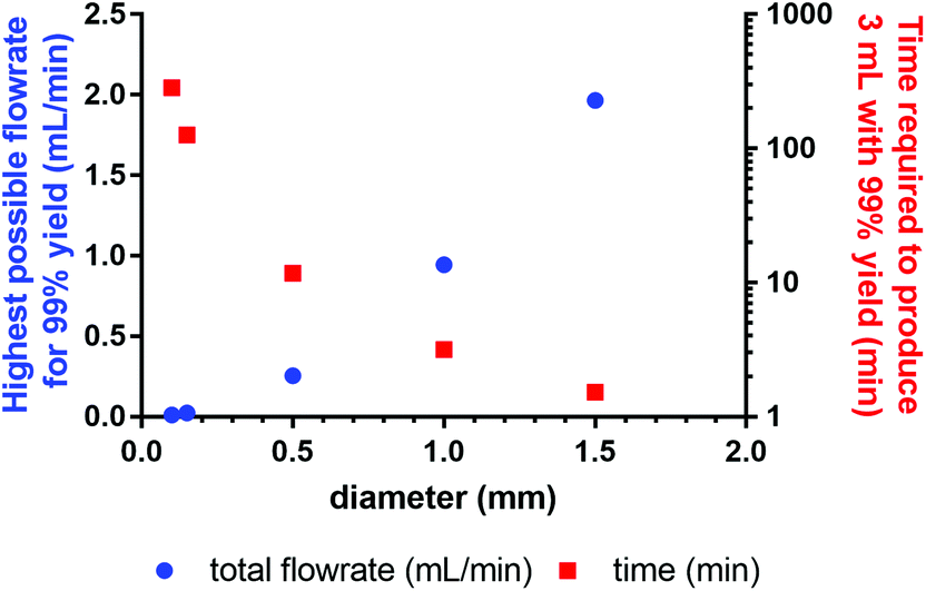 | ||
| Fig. 10 Dependence of highest possible flowrate to achieve 99% yield on the inner diameter of the reaction capillary, and time required for the reaction of 3 mL reaction solution. | ||
Conclusions
In this study, we presented a microfluidic setup that can determine kinetic association rate constants of radiopharmaceuticals at different temperatures. Currently, the system is limited to reactions that do not occur at room temperature, however, further work is on the way to design a system suitable for all types of reactions. With the current system we studied the kinetics of the formation of [177Lu]Lu-DOTA-TATE, and determined kinetic association rate constants and Arrhenius parameters for the first time. The experimental work was supported by computational simulations done with COMSOL Multiphysics®. Finally, we considered the clinical application of our results. The synthesis of [177Lu]Lu-DOTA-TATE is possible in a microfluidic system within 44 s at 80 °C (99% yield). The small diameter of the reaction capillary (100 μm), however, limits the throughput and would require high processing times for clinical amounts. Simulations showed that increasing the diameter to over 500 μm will allow for reaction times of under 12 min if 3 mL reaction volume (equaling 4 patient doses) are processed. These results demonstrate that a continuous, capillary system is a viable alternative to the conventional, batch-wise radiolabelling technique for which clinical reaction times of 30 min are applied.Conflicts of interest
There are no conflicts of interest to declare.Acknowledgements
We would like to thank Ernst van der Wal and Andries Oort from the DEMO team at TU Delft for the design and fabrication of the aluminium heating block. Financial support by the China Scholarship Council (No. 201506620056) was provided for the work of Zheng Liu.Notes and references
- G. Pascali, P. Watts and P. A. Salvadori, Nucl. Med. Biol., 2013, 40, 776–787 CrossRef CAS PubMed.
- P. Causey, K. Stephenson and J. Valliant, J. Nucl. Med., 2009, 50, 148 Search PubMed.
- G. Mate, D. Szikra, J. Simecek, S. Szilagyi, G. Trencsenyi, W. Hans-Jurgen, I. Kertesz and L. Galuska, J. Flow Chem., 2016, 6, 86–93 CrossRef.
- T. D. Wheeler, D. Zeng, A. V. Desai, B. Onal, D. E. Reichert and P. J. A. Kenis, Lab Chip, 2010, 10, 3387–3396 RSC.
- B. D. Wright, J. Whittenberg, A. Desai, C. DiFelice, P. J. A. Kenis, S. E. Lapi and D. E. Reichert, J. Nucl. Med., 2016, 57, 747–752 CrossRef PubMed.
- D. Zeng, A. V. Desai, D. Ranganathan, T. D. Wheeler, P. J. A. Kenis and D. E. Reichert, Nucl. Med. Biol., 2013, 40, 42–51 CrossRef CAS PubMed.
- H. Li, H. Zhou, S. Krieger, J. J. Parry, J. J. Whittenberg, A. V. Desai, B. E. Rogers, P. J. A. Kenis and D. E. Reichert, Bioconjugate Chem., 2014, 25, 761–772 CrossRef CAS PubMed.
- C. Rensch, B. Waengler, A. Yaroshenko, V. Samper, M. Baller, N. Heumesser, J. Ulin, S. Riese and G. Reischl, Appl. Radiat. Isot., 2012, 70, 1691–1697 CrossRef CAS PubMed.
- G. Pascali and P. A. Salvadori, Chim. Oggi Chem. Today, 2016, 34, 28–32 Search PubMed.
- S. Haroun, L. Wang, T. J. Ruth and P. C. H. Li, Chem. Eng. Process., 2013, 70, 140–147 CrossRef CAS.
- N. Miložič, M. Lubej, U. Novak, P. Žnidaršič-Plazl and I. Plazl, Chem. Biochem. Eng. Q., 2014, 28, 215–223 CrossRef.
- E. Häusler, P. Domagalski, M. Ottens and A. Bardow, Chem. Eng. Sci., 2012, 72, 45–50 CrossRef.
- A. E. Kamholz, B. H. Weigl, B. A. Finlayson and P. Yager, Anal. Chem., 1999, 71, 5340–5347 CrossRef CAS PubMed.
- L. Konermann, J. Phys. Chem. A, 1999, 103, 7210–7216 CrossRef CAS.
- L. Konermann, F. I. Rosell, A. G. Mauk and D. J. Douglas, Biochemistry, 1997, 36, 6448–6454 CrossRef CAS PubMed.
- D. L. Zechel, L. Konermann, S. G. Withers and D. J. Douglas, Biochemistry, 1998, 37, 7664–7669 CrossRef CAS PubMed.
- L. Konermann, B. A. Collings and D. J. Douglas, Biochemistry, 1997, 36, 5554–5559 CrossRef CAS PubMed.
- Y.-C. Chen and P. L. Urban, TrAC, Trends Anal. Chem., 2013, 44, 106–120 CrossRef CAS.
- C. Lento, G. F. Audette and D. J. Wilson, Can. J. Chem., 2014, 93, 7–12 CrossRef.
- T. M. Floyd, M. A. Schmidt and K. F. Jensen, Ind. Eng. Chem. Res., 2005, 44, 2351–2358 CrossRef CAS.
- M. Kakuta, D. A. Jayawickrama, A. M. Wolters, A. Manz and J. V. Sweedler, Anal. Chem., 2003, 75, 956–960 CrossRef CAS PubMed.
- W. A. P. Breeman, H. Sze Chan, R. M. S. de Zanger, M. K. Konijnenberg and E. de Blois, Curr. Radiopharm., 2016, 9, 8–18 CrossRef CAS PubMed.
- E. de Blois, H. S. Chan, R. de Zanger, M. Konijnenberg and W. A. P. Breeman, Appl. Radiat. Isot., 2014, 85, 28–33 CrossRef CAS PubMed.
- W. A. P. Breeman, E. De Blois, W. H. Bakker and E. P. Krenning, in Radionuclide Peptide Cancer Therapy, ed. M. Chinol and G. Paganelli, Taylor & Francis Group, 2006, ch. 5, pp. 119–126 Search PubMed.
- W. A. P. Breeman, M. de Jong, T. J. Visser, J. L. Erion and E. P. Krenning, Eur. J. Nucl. Med. Mol. Imaging, 2003, 30, 917–920 CrossRef CAS PubMed.
- W. A. P. Breeman, H. S. Chan and E. de Blois, J. Radioanal. Nucl. Chem., 2014, 302, 825–830 CrossRef CAS.
- T. Das, S. Chakraborty, S. Banerjee and M. Venkatesh, Appl. Radiat. Isot., 2007, 65, 301–308 CrossRef CAS PubMed.
- X. Zhu and S. Z. Lever, Electrophoresis, 2002, 23, 1348–1356 CrossRef CAS PubMed.
- X. Wang, T. Jin, V. Comblin, A. Lopez-Mut, E. Merciny and J. F. Desreux, Inorg. Chem., 1992, 31, 1095–1099 CrossRef CAS.
- P. W. Atkins and J. De Paula, Atkins’ Physical Chemistry, Oxford University Press, Oxford, 2006 Search PubMed.
- A. Harry Van den and R. Mudde, Transport Phenomena: The Art of Balancing, Delft Academic Press, Delft, 2014 Search PubMed.
- L. M. De Leon-Rodriguez and Z. Kovacs, Bioconjugate Chem., 2008, 19, 391–402 CrossRef CAS PubMed.
- S. Huclier-Markai, R. Kerdjoudj, C. Alliot, A. C. Bonraisin, N. Michel, F. Haddad and J. Barbet, Nucl. Med. Biol., 2014, 41, e36–e43 CrossRef CAS PubMed.
- S. P. Kasprzyk and R. G. Wilkins, Inorg. Chem., 1982, 21, 3349–3352 CrossRef CAS.
- B. Erik de, C. Ho Sze, K. Mark, Z. Rory de and A. P. B. Wouter, Curr. Top. Med. Chem., 2012, 12, 2677–2685 Search PubMed.
- C. S. Tsao and M. Young, Med. Sci. Res., 1996, 24, 473–475 CAS.
- M. G. Roig, Z. S. Rivera and J. F. Kennedy, Int. J. Food Sci. Nutr., 1996, 46, 107–115 CrossRef.
- M. Gallarate, M. E. Carlotti, M. Trotta and S. Bovo, Int. J. Pharm., 1999, 188, 233–241 CrossRef CAS PubMed.
Footnote |
| † Electronic supplementary information (ESI) available. See DOI: 10.1039/c7dt01830d |
| This journal is © The Royal Society of Chemistry 2017 |