DOI:
10.1039/C6CY01962E
(Communication)
Catal. Sci. Technol., 2017,
7, 47-50
Kinetic evidence: the rate-determining step for ammonia synthesis over electride-supported Ru catalysts is no longer the nitrogen dissociation step†
Received
14th September 2016
, Accepted 16th November 2016
First published on 30th November 2016
Abstract
Using kinetic analysis, we demonstrate that the rate-determining step for ammonia synthesis over Ru catalysts supported by electrides, such as [Ca24Al28O64]4+(e−)4 and Ca2N:e−, is not the N2 dissociation step but the subsequent surface reactions of N and H adatoms, in which case the Langmuir–Hinshelwood model should be used to describe the kinetics.
Ammonia is used as a raw material for the production of fundamental chemicals used to support our everyday lives. Therefore, catalytic ammonia synthesis is considered to be one of the most important breakthroughs in the chemical industry of the 20th century. According to eqn (1), the ammonia synthesis reaction is thermodynamically favourable at high pressure and low temperature.| | | 3H2 + N2 → 2NH3 ΔH(773 K) = −109 kJ mol−1 | (1) |
In common industrial processes, Fe- or Ru-based catalysts are used to accelerate the rate of reaction, even though the actual plant-operation temperature is still quite high at 400–600 °C.1,2 Such temperatures are required because the large bond dissociation energy of N2 (945 kJ mol−1) makes it difficult to be activated. The concept that dissociative chemisorption of N2 on a catalyst surface determines the overall rate of the ammonia synthesis reaction has been confirmed both experimentally and kinetically, and this has been applied in the Temkin rate equation to successfully describe the kinetics of industrial-scale ammonia synthesis.3
We have recently reported that Ru catalysts supported by electrides such as [Ca24Al28O64]4+(e−)4 (C12A7:e−),4–7 Ca2N:e− (ref. 8) and Y5Si3 (ref. 9) exhibit much higher activities than conventional Ru catalysts. Due to their low intrinsic work function, these electrides are unique in their ability to donate anionic electrons confined within them while maintaining chemical and thermal stability.10–12 In addition, surface hydrogen can be reversibly stored as hydride ions (H−) in the electride cages, so that hydrogen poisoning reported as a serious obstacle with Ru catalysts13–15 was not observed for Ru/electride catalysts at elevated pressures. These results suggested that ammonia synthesis over Ru/electride catalysts proceeded through a different mechanism from the conventionally accepted mechanism. N2 isotopic exchange reactions over Ru/C12A7:e−, Ru/C12A7:O2−, Ru–Cs/MgO, and Ru/CaO–Al2O3 indicated that only the Ru catalyst supported by the C12A7:e− electride exhibited a fast reaction rate with a low activation energy (Ea) of 58 kJ mol−1, compared with the 133–154 kJ mol−1 for the other non-electride supported catalysts.7 These results suggest that electrons released from the C12A7:e− electride can effectively promote N2 dissociation on the Ru surface.
In this study, a kinetic approach was taken to examine the RDS for ammonia synthesis over electride-supported catalysts Ru/C12A7:e− and Ru/Ca2N:e−. Investigation of the RDS was conducted by comparing a set of experimental reaction rates with modelled rate equations derived with the assumption that any step of N2 dissociation or subsequent NHx formation is the RDS.
Each catalyst used with 2 wt% Ru loading (0.1 g) was prepared according to a similar procedure to that described in our earlier reports.4,7,8 Ammonia synthesis was conducted in a silica glass reactor under a flow of a N2/H2/Ar mixture at 0.1 MPa. The reaction gas composition was varied at a constant temperature to acquire a variety of reaction rates for comparison with model equations. The reaction rates taken from various catalysts and reaction conditions are listed in Table S1,† together with the equilibrium values calculated from standard thermodynamic data. These rates were measured after a few hours of reaction time when the catalytic activity became stable. The reaction temperature was also selected to ensure that the obtained rates were sufficiently distant from the equilibrium values so that the influence of the reverse reaction (decomposition reaction of ammonia) was negligible.
The RDS for ammonia synthesis with each catalyst was examined by fitting the modelled rate equations to a set of obtained reaction rates. The rate equations were expressed by the Langmuir–Hinshelwood mechanism,16 and it was assumed that the catalytic ammonia synthesis reaction can be divided into 8 elementary steps (eqn (2)–(9)) and that any of steps 4–7 controls the overall rate of reaction due to the large Ea barrier. The following mechanisms for ammonia synthesis over Fe and Ru catalysts are widely acknowledged.17–19
| | | N(ad) + H(ad) → NH(ad), | (6) |
| | | NH(ad) + H(ad) → NH2(ad), | (7) |
| | | NH2(ad) + H(ad) → NH3(ad), | (8) |
where g and ad denote gaseous and adsorbed species, respectively. According to the Langmuir model, the coverage of vacant sites (
θv) is expressed according to the coverage of any occupied sites:
| | | θv = 1 − θH2 − θN2 − θH − θN − θNH − θNH2 − θNH3, | (10) |
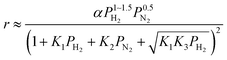
For the case where step 4 is the RDS, the other steps quickly reach equilibrium during the reaction and the overall rate of reaction (r) is approximated to the rate of step 4. When the partial pressure of ammonia at the outlet is sufficiently low enough that the influences of the reverse reaction of step 4 and NH3 adsorption can be ignored,15 the modelled rate equation can be expressed as a function of only the partial pressures of H2 (PH2) and N2 (PN2):
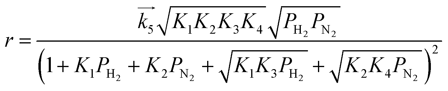
| |  | (11) |
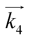
where

is the rate constant of the forward reaction in step 4 and
Ki is the equilibrium constant in step
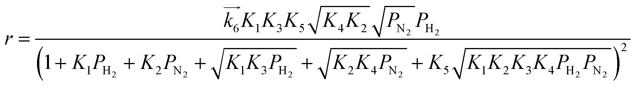
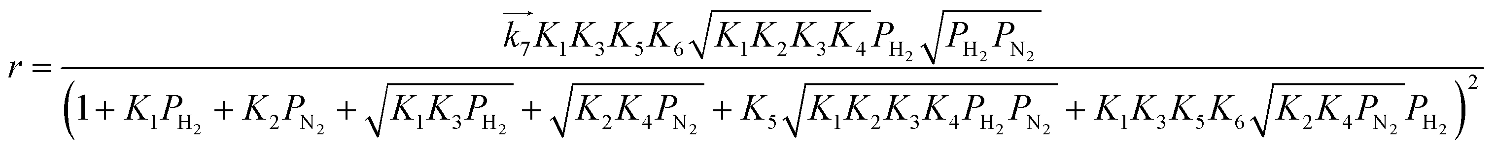
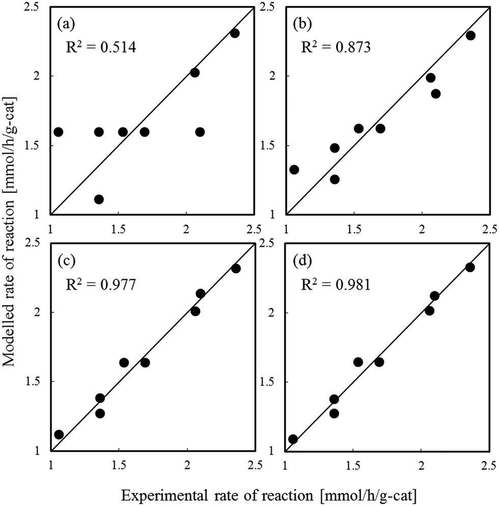
i. In the same manner, rate equations that correspond to steps 5–7 as the RDS are given in
eqn (12)–(14), respectively:
| |  | (12) |
| |  | (13) |
| |  | (14) |
These rate equations are functions of the partial pressures of H2 and N2 at the reaction temperature, where the rate constant of the forward reaction and any equilibrium constants can be constant. To identify the RDS for ammonia synthesis on each catalyst, derived equations were separately fitted into the sets of experimental data using a least squares method and evaluated to determine which equations best described the data.
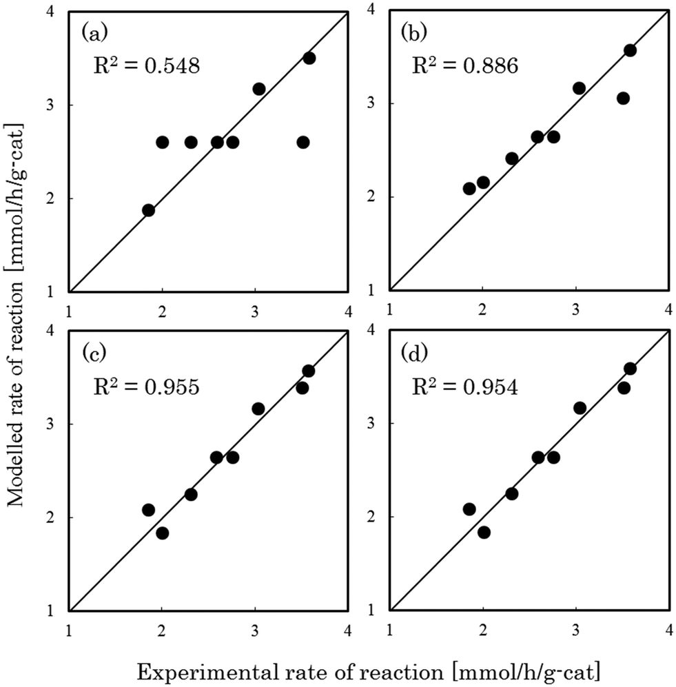
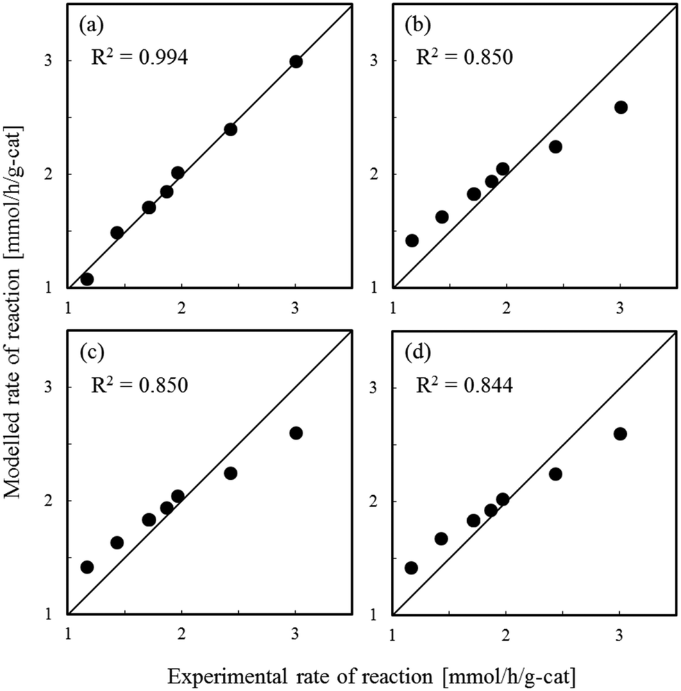
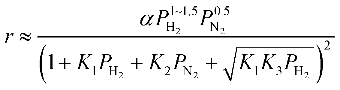
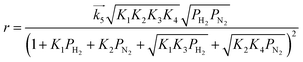
Fig. 1–3 show comparisons of the experimental reaction rates of the Ru/C12A7:e−, Ru/Ca2N:e−, and Ru–Cs/MgO catalysts, respectively, with the modelled rates obtained from the best-fit equations (eqn (11)–(14)). Coefficients of determination (R2) are also presented as an indication of better fits. Table 1 summarizes the R2 values obtained in a similar manner with various catalysts, including non-electride supported catalysts. The separate figures for the electride-supported catalysts (Fig. 1 and 2) show that the modelled rates derived from the RDS assumptions of steps 5–7 give better fits to the experimental rates than that of step 4. This result indicates that the RDS for ammonia synthesis over the electride-supported Ru catalysts is not the N2 dissociation step, but any of the steps for NHx formation (steps 5–7). On the other hand, for the non-electride supported catalysts Ru–Cs/MgO (Fig. 3) and Ru/C12A7:O2−, Ru/CaO–Al2O3, Ru/MgO, and Ru/CaNH (Fig. S1–S4†), the best fits to the modelled rates were derived from the RDS of step 4, which is already accepted for the catalytic ammonia synthesis reaction.
 |
| | Fig. 1 Best fit results for reaction rates over Ru/C12A7:e− with respect to the rate equations derived with the RDS assumed to be (a) step 4, (b) step 5, (c) step 6, and (d) step 7. | |
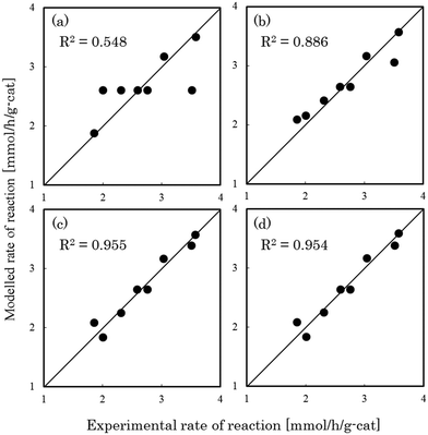 |
| | Fig. 2 Best fit results for reaction rates over Ru/Ca2N:e− with respect to the rate equations derived with the RDS assumed to be (a) step 4, (b) step 5, (c) step 6, and (d) step 7. | |
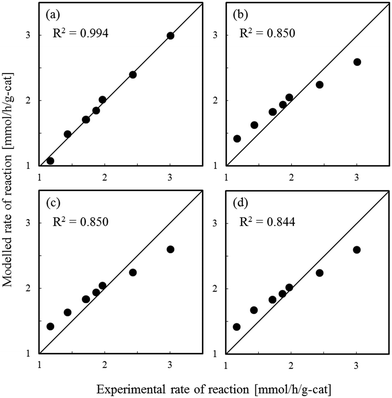 |
| | Fig. 3 Best fit results for reaction rates over Ru–Cs/MgO with respect to the rate equations derived with the RDS assumed to be (a) step 4, (b) step 5, (c) step 6, and (d) step 7. | |
Table 1 Coefficients of determination for steps 4–7 and activation energy for ammonia synthesis
| Sample |
Coefficient of determination, R2 [−] |
E
a
[kJ mol−1] |
| Step 4 |
Step 5 |
Step 6 |
Step 7 |
|
Taken from ref. 4, 7–9.
|
| Ru/C12A7:e− |
0.514 |
0.873 |
0.977 |
0.981 |
51 |
| Ru/C12A7:O2− |
0.967 |
0.796 |
0.752 |
0.797 |
104 |
| Ru/CaO–Al2O3 |
0.986 |
0.818 |
0.808 |
0.807 |
118 |
| Ru/MgO |
0.989 |
0.846 |
0.765 |
0.812 |
80 |
| Ru–Cs/MgO |
0.994 |
0.850 |
0.850 |
0.844 |
120 |
| Ru/Ca2N:e− |
0.548 |
0.886 |
0.955 |
0.954 |
60 |
| Ru/CaNH |
0.838 |
0.593 |
0.596 |
0.569 |
110 |
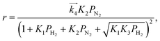
We have previously reported that the electride-supported Ru catalysts exhibited higher catalytic activity for ammonia synthesis with a lower Ea. Therefore, taking into consideration the corresponding N2 isotopic exchange reaction results with the distinctive features of electride materials, we conclude that adsorbed N2 molecules dissociate more smoothly on the catalyst surface by electron donation from the electrides, while any of the subsequent steps can be the RDS for the surface reactions of dissociated N and H. In this case, conventional rate equations derived from the Temkin model no longer describe the kinetics of ammonia synthesis over electride-supported Ru catalysts. Therefore, a new rate equation based on the newly determined RDS should be developed for industrial applications. A comparison of steps 5–7 on electride catalysts revealed that steps 6 and 7 gave the highest R2 values, and that these values were nearly identical. Therefore, it is difficult to determine which step is the RDS from this study, but summarizing the best-fit equations of steps 6 and 7 of the electride catalysts, a general form of the rate equation is given as follows.
| |  | (15) |
where
α is a function of temperature. Under industrial conditions operated at high pressures, the NH
3 concentration would be high enough and it cannot be ignored any more. Therefore, in view of the actual application, we would derive a rate equation modified with a term of NH
3 partial pressure in future work.
The authors thank M. Okunaka and S. Fujimoto for technical assistance. This work was supported by funds from the Accelerated Innovation Research Initiative Turning Top Science and Ideas into High-Impact Values (ACCEL) program of the Japan Science and Technology Agency (JST). A portion of this work was supported by a Kakenhi Grant-in-Aid (No. 15H04183) from the Japan Society for the Promotion of Science (JSPS).
Notes and references
-
C. H. Bartholomew and R. J. Farrauto, in Fundamentals of industrial catalytic processes, John Wiley & Sons, Inc., New Jersey, 2nd edn, 2006, ch. 6, p. 371 Search PubMed.
-
J. R. Jennings, Catalytic ammonia synthesis, fundamentals and practice, Plenum Press, New York, 1991, ch. 7, p. 253 Search PubMed.
- M. Temkin and V. Pyzhev, Acta Physicochim. URSS, 1940, 12, 327–356 CAS.
- M. Kitano, Y. Inoue, Y. Yamazaki, F. Hayashi, S. Matsuishi, T. Yokoyama, S. W. Kim, M. Hara and H. Hosono, Nat. Chem., 2012, 4, 934–940 CrossRef CAS PubMed.
- Y. Inoue, M. Kitano, S. W. Kim, T. Yokoyama, M. Hara and H. Hosono, ACS Catal., 2014, 4, 674–680 CrossRef CAS.
- S. Kanbara, M. Kitano, Y. Inoue, T. Yokoyarna, M. Hara and H. Hosono, J. Am. Chem. Soc., 2015, 137, 14517–14524 CrossRef CAS PubMed.
- M. Kitano, S. Kanbara, Y. Inoue, N. Kuganathan, P. V. Sushko, T. Yokoyama, M. Hara and H. Hosono, Nat. Commun., 2015, 6, 6731 CrossRef CAS PubMed.
- M. Kitano, Y. Inoue, H. Ishikawa, K. Yamagata, T. Nakao, T. Tada, S. Matsuishi, T. Yokoyama, M. Hara and H. Hosono, Chem. Sci., 2016, 7, 4036–4043 RSC.
- Y. Lu, J. Li, T. Tada, Y. Toda, S. Ueda, T. Yokoyama, M. Kitano and H. Hosono, J. Am. Chem. Soc., 2016, 138, 3970–3973 CrossRef CAS PubMed.
- S. Matsuishi, Y. Toda, M. Miyakawa, K. Hayashi, T. Kamiya, M. Hirano, I. Tanaka and H. Hosono, Science, 2003, 301, 626–629 CrossRef CAS PubMed.
- Y. Toda, H. Yanagi, E. Ikenaga, J. J. Kim, M. Kobata, S. Ueda, T. Kamiya, M. Hirano, K. Kobayashi and H. Hosono, Adv. Mater., 2007, 19, 3564–3569 CrossRef CAS.
- K. Lee, S. W. Kim, Y. Toda, S. Matsuishi and H. Hosono, Nature, 2013, 494, 336–340 CrossRef CAS PubMed.
- F. Rosowski, A. Hornung, O. Hinrichsen, D. Herein, M. Muhler and G. Ertl, Appl. Catal., A, 1997, 151, 443–460 CrossRef CAS.
- T. Becue, R. J. Davis and J. M. Garces, J. Catal., 1998, 179, 129–137 CrossRef CAS.
- S. E. Siporin and R. J. Davis, J. Catal., 2004, 225, 359–368 CrossRef CAS.
- I. Langmuir, Trans. Faraday Soc., 1922, 17, 621–654 RSC.
- O. Hinrichsen, F. Rosowski, M. Muhler and G. Ertl, Chem. Eng. Sci., 1996, 51, 1683–1690 CrossRef CAS.
- S. Dahl, J. Sehested, C. J. H. Jacobsen, E. Tornqvist and I. Chorkendorff, J. Catal., 2000, 192, 391–399 CrossRef CAS.
- G. Ertl, J. Vac. Sci. Technol., A, 1983, 1, 1247–1253 CAS.
Footnote |
| † Electronic supplementary information (ESI) available: Catalytic performance, fitting results. See DOI: 10.1039/c6cy01962e |
|
| This journal is © The Royal Society of Chemistry 2017 |
Click here to see how this site uses Cookies. View our privacy policy here. 

 is the rate constant of the forward reaction in step 4 and Ki is the equilibrium constant in step i. In the same manner, rate equations that correspond to steps 5–7 as the RDS are given in eqn (12)–(14), respectively: