
 Open Access Article
 This Open Access Article is licensed under a
 Creative Commons Attribution 3.0 Unported Licence
Control of electro-chemical processes using energy harvesting materials and devices
Yan
Zhang†
 ,
Mengying
Xie†
*,
Vana
Adamaki
,
Hamideh
Khanbareh
and
Chris R.
Bowen
,
Mengying
Xie†
*,
Vana
Adamaki
,
Hamideh
Khanbareh
and
Chris R.
Bowen
Materials and Structures Centre, Department of Mechanical Engineering, University of Bath, BA1 7AY, UK. E-mail: M.Xie@bath.ac.uk
First published on 10th November 2017
Abstract
Energy harvesting is a topic of intense interest that aims to convert ambient forms of energy such as mechanical motion, light and heat, which are otherwise wasted, into useful energy. In many cases the energy harvester or nanogenerator converts motion, heat or light into electrical energy, which is subsequently rectified and stored within capacitors for applications such as wireless and self-powered sensors or low-power electronics. This review covers the new and emerging area that aims to directly couple energy harvesting materials and devices with electro-chemical systems. The harvesting approaches to be covered include pyroelectric, piezoelectric, triboelectric, flexoelectric, thermoelectric and photovoltaic effects. These are used to influence a variety of electro-chemical systems such as applications related to water splitting, catalysis, corrosion protection, degradation of pollutants, disinfection of bacteria and material synthesis. Comparisons are made between the range harvesting approaches and the modes of operation are described. Future directions for the development of electro-chemical harvesting systems are highlighted and the potential for new applications and hybrid approaches are discussed.
 Yan Zhang | Yan Zhang obtained her BSc and PhD degrees in Materials Science from Central South University in 2008 and 2013, respectively. She worked in Hunan University from 2014 to 2016. Her PhD work concentrated on the fine adjustment of aligned porous structures and lead-free porous piezoelectric composite for biomedical application. She is currently a Marie-Skłodowska-Curie Fellow in Department of Mechanical Engineering in University of Bath, working on porous materials, ferroelectrics, bio-piezoelectric composite, sensors and energy harvesting applications since 2016. |
 Mengying Xie | Mengying Xie has a BSc degree in Applied Physics from Tianjin University, China (2006–2010) and a PhD in Mechatronics Engineering from the University of Auckland, New Zealand (2010–2015). In 2016 she joined NEMESIS project in University of Bath as a postdoc. Her PhD work exploited the unique properties of PDMS into various wearable applications such as a flexible memory device, energy harvester from human motion and flexible force sensors. Her research area in Bath includes piezoelectric/pyroelectric energy harvesting for water splitting, piezoelectric sensors and smart energy storage applications. |
 Vana Adamaki | Vaia Adamaki holds a diploma in Applied Physics and a MSc in Material Science and Technology and completed her PhD in 2014 at the University of Bath. Her PhD work was on the electrical and mechanical properties of Ti-suboxides and fibres for sensing and energy applications and now she focuses on finding efficient electrodes for water splitting. |
 Hamideh Khanbareh | Hamideh Khanbareh was awarded her PhD in Aerospace Engineering from Delft University of Technology in June 2016. She started a new role as a Prize Fellow in the Materials and Structures Research Centre within the Department of Mechanical Engineering, in University of Bath since September 2016. Her main research interests are in designing novel electroceramic–polymer composites for piezo- and pyroelectric sensing/energy harvesting applications. Her research includes experimental synthesis, characterisation as well as analytical and numerical modelling. |
 Chris R. Bowen | Christopher Rhys Bowen has a BSc degree in Materials Science from the University of Bath (1986–1990) and a DPhil from the University of Oxford (1990–1993). Post-doctoral work was at Tecnische Universität Harburg-Hamburg and University of Leeds (1994–1996). He was Senior Scientist at the Defence Evaluation and Research Agency from 1996–1998. He joined Bath as a Lecturer in 1998 and is now Professor of Materials and ERC Advanced Investigator, ERC Grant Agreement No. 320963 on Novel Energy Materials, Engineering Science and Integrated Systems (NEMESIS). Research includes energy harvesting, ferroelectrics and functional ceramics. |
1. Introduction
Energy harvesting of heat, light and mechanical vibrations remains a vibrant topic. In many cases the harvester generates electrical energy, which is subsequently rectified, conditioned and stored within capacitors or batteries for applications such as wireless and self-powered sensors or low-power electronics. This review covers a new and emerging area that aims to directly couple energy harvesting materials and devices with electro-chemical systems.There are excellent reviews available on electro-chemical storage materials1,2 which focus on electro-chemical energy storage configurations, such as flexible, fiber and transparent systems1 and reviews which describe the potential of combining harvesting materials with conventional storage mechanisms to form self-powered electro-chemical energy storage systems (SEESs),2 and multi-functional energy devices using supercapacitors and electro-chromic based systems.3 Hybrid systems that to combine a variety of mechanical, thermal and light harvesting approaches have also been recently examined by Lee et al.4
This review will focus on exploitation of the harvested energy in electro-chemical applications. This will include water splitting, water treatment, catalysis, corrosion protection, degradation of pollutants, disinfection of bacteria and material synthesis. The intention of the review is not to overview the energy generation mechanisms, as these have been covered in detail elsewhere; for example see ref. 5–12. This review will provide a detailed overview of work to date on how energy harvesting materials and devices have been used to influence electro-chemistry; and aims to inspire new efforts in this emerging area. The coupling of energy generation with electro-chemistry is not entirely new and the intermittent nature of large scale renewable power generation methods, such as solar power13 and wind energy,14 has led to interest in using electrical energy to generate hydrogen from water which is then stored. Hybrid wind and light approaches are also under consideration.15 However for smaller scale harvesting applications, typically in the μW to mW range, this is a more recent topic and has received significant recent attention for a diverse range of applications.
Harvesting approaches to be covered include pyroelectric,5 piezoelectric,6,7 triboelectric,7,8 flexoelectric,10 thermoelectric9 and photovoltaic12 effects, which are shown schematically in Fig. 1. The pyroelectric, piezoelectric and flexoelectric effects generate an electrical charge as a result of a change in polarisation of a material due to the application of a temperature change, applied stress or strain gradient respectively, while the photovoltaic effect arises from electrons being excited to the conduction band by solar energy. We will see in the review that these mechanisms of charge generation can take the form of an external bulk material or harvesting device that is connected to an electro-chemical cell, or it can take the form of electro-active particles that are in direct contact with an electrolyte; as shown by the pyroelectric and piezoelectric examples in Fig. 1. Triboelectric charges are produced as a result of a frictional contact between two materials which become electrically charged; these are typically used as motion harvesting triboelectric nanogenerators (TENGs) which are electrically connected to an electro-chemical cell. The thermoelectric effect generates charge from a thermal gradient between two dissimilar conductors due to the Seebeck effect and is also typically used as a harvesting device which is connected to an electro-chemical cell. We will see that in some cases hybrid approaches are utilised that use more than one of the harvesting mechanisms shown in Fig. 1 or employ additional charge generation mechanisms, such a solar harvesting and photo-generated carriers. Table 1 provides a summary of the electro-chemical applications, harvesting materials and modes of operation, and we will refer to this table throughout the review. The interaction of the harvesting material or device with electro-chemical systems will now be described, and their potential applications. Finally, potential future directions will be explored.
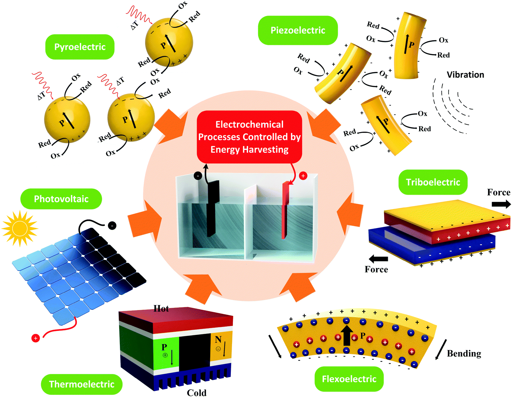 | ||
| Fig. 1 Pyro-electric (temperature cycles), thermo-electric (temperature gradients), piezo-electric (strain), tribo-electric (motion), flexo-electric (strain gradient) and photovoltaic (solar excitation) charge generation mechanisms which are used to control electro-chemical reactions. The thermoelectric and triboelectric approaches typically use external devices, while the pyroelectric, piezoelectric and photovoltaic mechanisms can utilise external devices or particulates that are in direct contact with the electrolyte; as shown in upper images. | ||
| Electro-chemical application | Primary electro-chemical mechanism | Energy harvesting route | Primary material(s) used | Energy source for harvesting | Configuration of harvester relative to electro-chemical reactor | Short-circuit current (Isc), open-circuit (Uoc) | Electrical output (direct: (AC pulse) rectification/transformation or indirect: stored in the supercapacitor/battery) | Ref. | ||
|---|---|---|---|---|---|---|---|---|---|---|
| I SC | U OC | Condition | ||||||||
| Water Splitting |
Anode: 4OH− → 2H2O + O2 + 4e−
2NaCl →2Na+ + Cl2 + 2e− Cathode: 4H++ 4e− → 2H2 |
Pyro-electric effect |
PZT
BaTiO3 PbTiO3 (theoretical) |
Thermal
Thermal Thermal |
External
Internal Internal |
5 μA
— — |
4 V
— — |
Working freq. 0.1 Hz
— — |
Rectification and capacitor
— — |
20 |
| Piezo-electric effect |
ZnO/BaTiO3
PMN–PT PZT-5 ZnO |
Water wave
Vibration Vibration Water wave + light |
Internal
Internal External Internal |
—
— — — |
—
— 12 V 2 V |
Ultrasonic wave vibration
0.01 to 0.08 ppb/oscillation 46.2 Hz/0.07N Ultrasonic wave vibration + xenon arc lamp (100 mW cm−1) |
Transformation
Transformation Rectification Transformation |
49 | ||
| Tribo-electric effect |
PA-PFA
Gold–Kapton TiO2 Nanowire/graphite Cu-PTFE ITO-PTFE |
Mechanical energy
Flowing kinetic energy Wind Biokinetic energy Linear motor |
External |
0.06 mA
1 mA 0.1 mA 1.5 mA 0.12 mA |
110 V
240 V 150 V 15 V 200 V |
—
600 rmp Wind speed of 15 m s−1 500 rmp 60 N |
Li-ion battery
Supercapacitor Rectification Rectification Li-ion battery |
97 | ||
| Thermo-electric effect |
FeSO4, HI
Carbon Silicon photoelectrode TiO2 nanotube arrays |
Solar energy
Heat water bath Solar energy Heat water bath |
External
External External External |
—
2 mA — — |
2 V
200–1200 mV 350 mV 0.5 V |
Light of wavelength from 4k to 6k Å, Temp. gradient of 150 °C
Hot side: 35 to 55 °C, cold side: room temp Temp. gradient of 10 °C Hot side: 70 °C |
AC pulse
AC pulse AC pulse AC pulse |
178,179 | ||
| Photovoltaic effect |
GaInP/GaAs/Ge
InGaP/GaAs/GaInNAsSb |
Solar simulator | External |
∼160 mA
∼185 mA |
∼2.2 V
3.21 V |
150 W Xenon lamp
550 W Xenon lamp |
Direct | 197 | ||
| Degradation and water treatment |
Anode: 2Cl− → Cl2 + 2e−
h+ + OH− → ˙OH M (Metal) → Mn+ + ne− Cathode: 2H+ + 2e− → H2 O2 + e− → O2− Cu2+ + 2e− → Cu nH2O + ne− → n/2 H2+ nOH− |
Pyro-electric effect |
LiTaO3
LiNbO3 BaTiO3–Pd particle BiFeO3 BaTiO3 ZnO PZT + PDMS-PET |
Thermal
Thermal Thermal Thermal Thermal Thermal Thermal + mechanical |
Internal
Internal Internal Internal Internal Internal External |
—
— — — — — — |
—
— — — — — — |
32 min per cycle
32 min per cycle — 27 to 38 °C per cycle 30 to 47 °C per cycle 22 to 62 °C per cycle — |
Direct
Direct Direct Direct Direct Direct Rectification |
31 31 |
| Piezo-electric effect |
BaTiO3
PZT BaTiO3/metal ions ZnO ZnSnO3 Zn1−xSnO3 CuS/ZnO Ag2O/ZnO Ag/ZnO |
Water wave
Water wave Water wave Vibration + light Stress + light Stress + light Stress + light Stress + light Stress + light |
Internal
Internal Internal Internal Internal Internal Internal Internal Internal |
—
— — — — — — — — |
—
— — — — — — — — |
Ultrasonic wave vibration
Ultrasonic wave vibration Ultrasonic wave vibration 1 Hz/1 cm of vibration & 50 W/313 nm 0.29–0.94 GPa stress & 15 W/254 nm 0.4–0.6 GPa stress & 30 W/330 nm Ultrasonic probe (200 W) & solar light (500 W) Ultrasonic probe (200 W) & UV light (50 W) Ultrasonic probe (200 W) & solar light (500 W) |
Transformation
Transformation Transformation Transformation Transformation Transformation Transformation Transformation Transformation |
57 | ||
| Tribo-electric effect |
Al-PTFE
ITO/SiN-PDMS PET-PDMS TiO2 Nanowire/PTFE ITO-PTFE Copper-Kapton Copper-Kapton Copper-Kapton Copper-FEP Al-PTFE Copper-FEP Al-PTFE Copper-PTFE Alo-Kapton |
Linear motor
Mechanical energy Mechanical energy Wastewater wave Water wave Flowing kinetic energy Linear motor Motor Flowing wastewater Ambient natural wind Water Vibration Vibration Vibration |
External |
—
∼85 nA 0.2 μA ∼1.2 μA 0.12 mA 0.45 μA 69.9 μA 13 mA 3.5 mA 15 μA 8 mA 0.56 mA 1.2 mA 0.2 μA |
30 V
2.5 V 12 V ∼7 V 270 V 2 V 845.6 V 3 V 10 V 50 V 16 V 793 V 1300 V 600 V |
—
Working freq. of 1 Hz — Wave speed of 1.4 m s−1 Working freq. of 2 Hz 650 rmp Vibration freq. of 2.08 Hz 450 rmp Water flow rate of 3 L min−1 Wind speed of 10 m s−1 1500 rmp Vibration freq. of 3 Hz Vibration freq. of 4 Hz 1000 rmp |
Rectification
Rectification Li-ion battery Rectification Rectification Transformation/rectification Transformation/rectification Transformation/rectification Transformation/rectification Capacitor Supercapacitor Rectification Rectification Transformation/rectification |
104 | ||
| Photovoltaic effect |
GaInP/GaAs/Ge
Zinc |
Solar simulator | External |
∼6.5 mA
150 mA |
1.34 V
— |
1 sun density spectrum
∼240 W silicon cells |
Direct
Direct |
201 | ||
| Corrosion protection | By generating charge, the surface of the protected cathode is below the corrosion potential. | Pyro-electric effect | PVDF + PTFE | Thermal + mechanical | External | Rectification | 38 | |||
| Piezo-electric effect | PVDF + PTFE | Thermal + mechanical | External | Rectification | 38 | |||||
| Tribo-electric effect |
Copper–Kapton
Nylon-PVDF Ag-PET PET-PDMS Kapton-PTFE Al-PTFE PVDF-PPy Nanowire Gum wrapper-PVDF |
Motor
Motor Water wave External stimulation Water wave Vibration Motor Motor |
External |
32.1 μA
51.4 μA 5 μA 130 μA 13 μA 0.42 μA 33.7 μA 30 μA |
310 V
1008 V 75 V 500 V 230 V 8 V 351 V 1000 V |
1000 rmp
Working freq. of 7.5 Hz Wave speed of 0.2 m s−1 Working freq. of 1 Hz Working freq. of 1.25 Hz Vibration freq. of 3 Hz Working freq. of 8 Hz Working freq. of 5 Hz |
Rectification
Capacitor Supercapacitor Rectification Rectification Rectification Rectification Capacitor |
120 | ||
| Self-charging power cells | Polyethylene separator of a conventional Li battery is replaced with a piezoelectric material. Under the compressive strain the produced piezoelectric field of the piezoelectric separator drives charges from the cathode to the anode, thereby recharging the power cell | Piezo-electric effect |
PVDF
CuO/PVDF mesoporous PVDF Highly porous PVDF PVDF-PZT PVDF-ZnO P(VDF-TrFE) foam Li-alloyed Si (piezo-resistive) BaTiO3 nanoparticles |
Compressive strain
Compressive strain Compressive strain Compressive strain Compressive strain Compressive strain Compressive strain Compressive strain Compressive strain |
Internal
Internal Internal Internal Internal Internal Internal Internal Internal |
—
— — — — — — 14.5 μA — |
—
— — — — — 0.31 V 0.023 V — |
Compressive strain
18 N, 1 Hz 22–34 N, 1.8 Hz 141, 282, 423 mJ, 1 Hz 10 N, 1.5 Hz 9.8–18.8 N finger tapping 70 N, 5 Hz 0.3 Hz finger tapping Deformation of Si nanoparticles during lithiation (1.7 GPa) |
Transformation
Transformation Transformation Transformation Transformation Transformation Transformation Transformation Transformation |
75 |
| Electro-deposition & oxidation | Generated charges can reduce the metal cations to form a coherent metal coating on an electrode | Tribo-electric effect |
Kapton-PMMA
PTFE-PPy |
Vibration
Shaker motor |
External |
6 μA
68 μA |
110 V
200 V |
—
Working freq. of 10 Hz |
Rectification
Supercapacitor |
126 |
| Thermo-electric effect | PEDOT-PSS | Heat | External | — | 50 mV | Temp. gradient of 1 K | Supercapacitor | 226 | ||
| Chemical sensor | Using a modifying agent in the power source to detect chemicals. | Tribo-electric effect |
Au nanoparticles-PDMS
Al-PA PVDF-nylon β-CD/TiO2-PTFE Al-PTFE Cu-FEPAAO-PTFE Al-melamine Al-PTFE Copper-PZT |
Controlled force
Liquid dripping Vibration Water wave Vibration Blowing Water External stimulation External force External agitation |
External |
63 μA
— 81 μA 80 μA 33 μA ∼4 μA ∼0.2 μA 6.18 μA 1.86 μA 3.7 μA |
105 V
∼70 V 1163 V 70 V 116 V ∼17.5 V ∼150 V 23.8 V 33.7 V — |
Force of 50 N, freq. of 5 Hz
Water drop Triggering freq. of 5 Hz Wave speed of 1.4 m s−1 Force of 60 N, freq. of 1 Hz Blowing speed of 2 m s−1 Water flow rate of 3 L min−1 Working freq. of 3 Hz Working freq. of 5 Hz — |
Rectification
AC output Rectification Rectification AC output AC output Rectification AC output AC output AC output |
132 |
| Thermo-electric effect | Al-PTFE gelatin/glycerol | Aspiration & dispensing of the pipet from the solution | — | ∼0–0.5 mV | Aspiration of the solution by the pipet tip and temp. gradient from −4 to 64 °C | Capacitor | 224 | |||
| Electro-chromic | Injected charges can energize the electro-chemical redox reactions. | Tribo-electric effect |
ITO/PET-PDMS
POM-PTFE Fluorocarbon-ITO Copper-PDMS Copper-PTFE PDMS-human skin |
Wind
Force Vibration Motor Finger-induced strain Human motion |
External |
45 μA
434.3 μA 100 μA ∼0.15 μA 3.5 μA 3.1 μA |
140 V
236.8 V 200 V ∼3.75 V 90 V 56 V |
Wind speed of 16.1 m s−1
Force of 400 N, freq. of 5 Hz Working freq. of 10 Hz 15 N, 3 m s−2 4 Hz — |
Rectification
Rectification Capacitor AC output Rectification Rectification |
139 |
| Thermo-electric effect | PEDOT-PSS | Heat | External | — | 50 mV | Temp. gradient of 1 K | Supercapacitor | 226 | ||
| Biological related | Bone healing | Piezo-electric effect | Collagen | Deformation | Internal | — | — | — | Transformation | 86 |
| Ion pumping in bio membranes | Flexo-electric effect | Deformation | Internal | — | — | — | Transformation | 158 and 159 | ||
| Self-healing structures | By mimicking the ability of biological structures to redistribute their structural mass in response to dynamic loads | Piezo-electric effect | PVDF-HFP & PZT | Deformation | Internal | — | — | — | Transformation | 89 |
| Ice forming and polymer patterning | Local electric field leads to the formation of the ice-like nuclei or electrowetting effect | Pyro-electric effect |
LiTaO3
SrTiO3 PVDF Amino acid crystals LiNbO3 |
Electric field
Electric field Electric field Electric field Thermal contact |
Contact
Contact Contact Contact Contact |
—
— — — — |
—
— — — — |
—
— — — — |
—
— — — — |
41 |
| Other applications | Thermoelectric polymer with large Seebeck coefficient | Thermo-electric effect | PEDOT:PSS | Peltier heater | External | — | ∼5 mV | Temp. gradient of 1, 2.5 and 3.5 K, relative humidity 100% | AC pulse | 184 |
2. Pyro-electro-chemistry
2.1 Pyro-electro-chemical water splitting
The emission of CO2 has been a significant contributor to global warming and climate change. As a result, renewable and alternative energy sources have become one of the primary topics of interest at a global level. Hydrogen fuel, is one of the most promising energy conversion technologies due to its high energy density and low greenhouse gas emission. Today, over 90% of hydrogen is produced from fossil fuels and biomass which produces greenhouse gases as a byproduct.16 As an alternative, hydrogen production from clean and renewable resources has gained interest over recent decades. Water splitting, or electrolysis, by electricity or light (solar energy) is one of the most convenient ways of addressing this problem.17–19 In order to trigger electrolysis and produce hydrogen gas, the overall potential difference between the anode and cathode is critical and, thermodynamically, the necessary potential difference is at least 1.23 V. Eqn (1) and (2) provide the minimum electrode potential for electrolysis at pH = 0. However, an excess energy, termed an overpotential, is required to overcome activation energy barriers during the reaction. Additional factors are that some of the products may catalytically reconvert to water, oxygen may oxidise the anode, and a double layer capacitance may be formed.| Anode: E = −1.23 V | (1) |
| Cathode: E = 0.00 V | (2) |
| m = [Q·M]/F·z | (3) |
Pyroelectric energy harvesters, as a potential energy source, have been used in an effort to split water. The pyroelectric charge (Q) generated for a temperature change (ΔT) is given by,
| Q = p·A·ΔT | (4) |
| ΔV = [p/(εT33)]·h·ΔT | (5) |
 | ||
| Fig. 2 Pyroelectric water splitting. (a) Open circuit voltage generated for 1 °C change vs. pyroelectric film thickness. Critical potential for electrolysis is indicated as 1.5 V; ΔV = [p/(εT33)]·h·ΔT. Reproduced from ref. 20. Copyright (2017) with permission from Elsevier. (b) Schematic of a pyroelectric used as an external power source for water splitting. | ||
Rather than using the pyroelectric materials as an external charge source, Belitz et al. recently developed a pyroelectric water splitting system where a BaTiO3 single crystal powder were brought into direct contact with distilled water in a polystyrene container which was subjected to a cyclic temperature change from 40 °C to 70 °C.23 A specially designed coulometric solid electrolyte detector indicated that 300 Vol.-ppb hydrogen was generated after a small number of pyroelectric cycles. The advantage of this approach, compared to using a bulk materials, is that using finely dispersed pyroelectric particulates enables the area of the pyroelectric to be greatly increased, and therefore increase the available charge for hydrogen production (eqn (3) and (4)).
Materials that exhibit high pyroelectric coefficients are typically ferroelectric that have a switchable polarisation, and the direction of polarisation can affect its surface stoichiometry and electronic structure, and therefore adsorption energy. The modification of ferroelectric surfaces to control surface chemistry and enhance catalytic properties has been studied in the areas of adsorption, desorption and photo-catalysis.24,25 In recent papers,25,26 Kakekhani et al. proposed a pyro-catalytic reaction that is activated by cycling a material between two ferroelectric polarisation states (one surface state with a strong adsorption potential and the other surface state with a strong desorption potential). Density functional theory (DFT) indicated that ferroelectric PbTiO3 can effectively convert SO2 to SO3 and can be used to control binding energies and hence decompose NOx into N2 and O2 by using a positive and negative polarisation. In addition, the potential of catalysing the partial oxidation of methane to methanol was reported.27 DFT was also used examine the potential of pyroelectric materials for water splitting.28 In the modelling approach, the surface of a ferroelectric lead titanate (PbTiO3) material was cycled between its low temperature ferroelectric state and high temperature para-electric phase by thermally cycling above and below its Curie temperature (Tc). In the lower temperature ferroelectric and polarised state, H2O molecules are thought to dissociate on the negatively poled surface of the lead titanate to produce bound atomic hydrogen (see blue region of Fig. 3 where T < Tc). When the material is heated to the higher temperature non-polarised and para-electric phase, the hydrogen atoms recombine to form weakly bound H2, thereby creating a clean surface that is ready for the next thermal cycle (see red region of Fig. 3 where T > Tc). This provides an intriguing approach to harvest thermal fluctuations to produce hydrogen, although no experimental evidence has been reported to date.
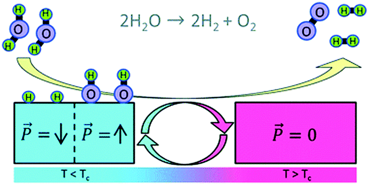 | ||
| Fig. 3 Water splitting by thermal cycling between a polarised (left, blue) and para-electric (red, right) surface of a pyroelectric material. Two water molecules are dissociated on the polarised surface to produce bound atomic hydrogen and when the surface is switched to the para-electric phase, the H atoms recombine to form weakly bound H2. Reproduced from ref. 28 with permission from The Royal Society of Chemistry. | ||
2.2 Pyro-electro-catalysis
The demand for clean water continues to rise due to worldwide growth in our population and agriculture, and increased industrial development. When heavy metals, bacteria and organic dyes enter our water, it can be difficult to treat and can lead to health and environmental problems and therefore new technologies for their removal has become desirable.29 In this regard, the use of pyro-electro-catalysis, which combines the pyroelectric effect and electro-chemical oxidation–reduction reactions, has been studied and used for the disinfection of bacteria and decomposition of a variety of toxic and hazardous organic compounds in aqueous environments.![[P with combining right harpoon above (vector)]](https://www.rsc.org/images/entities/i_char_0050_20d1.gif) ) of the ferroelectric LiTaO3 (shown as red circles). When the material is heated in Fig. 4(b), the polarisation of the pyroelectric is reduced so that some of the bound charge is now free to take part in reduction–oxidation reactions (Red–Ox) until the excess (free) charges are consumed in Fig. 4(c). When the material is subsequently cooled the polarisation of the material increases and charges move to the surface to balance the uncompensated screening charge carriers, leading to further Red–Ox reactions. It should be noted from Fig. 4 that the polarity of the charges moving to each surface changes depend on whether the material is undergoing a heating cycle (a polarisation decrease) or a cooling cycle (a polarisation increase). To demonstrate the potential of pyroelectric disinfection, Fig. 5 shows vitality staining of bacterial cultures which show the disinfection of the E. coli bacterial cells due to the pyroelectric effect of LiTaO3 powders; the E. coli were killed after thermal treatment of LiTaO3 for three hours.
) of the ferroelectric LiTaO3 (shown as red circles). When the material is heated in Fig. 4(b), the polarisation of the pyroelectric is reduced so that some of the bound charge is now free to take part in reduction–oxidation reactions (Red–Ox) until the excess (free) charges are consumed in Fig. 4(c). When the material is subsequently cooled the polarisation of the material increases and charges move to the surface to balance the uncompensated screening charge carriers, leading to further Red–Ox reactions. It should be noted from Fig. 4 that the polarity of the charges moving to each surface changes depend on whether the material is undergoing a heating cycle (a polarisation decrease) or a cooling cycle (a polarisation increase). To demonstrate the potential of pyroelectric disinfection, Fig. 5 shows vitality staining of bacterial cultures which show the disinfection of the E. coli bacterial cells due to the pyroelectric effect of LiTaO3 powders; the E. coli were killed after thermal treatment of LiTaO3 for three hours.
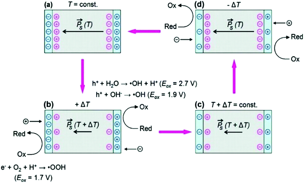 | ||
| Fig. 4 The pyro-electro-catalytic cycle due to thermal cycling of a pyroelectric crystal in aqueous conditions and subsequent surface reactions. (a) and (c) are the equilibrium condition at different temperatures, while (b) and (d) show the surface potential due to a transient imbalance between polarisation (red circles) and screening charges (blue circles). If the surface potential in (b) and (d) exceeds the oxidation potentials, surface-adsorbed molecular species can undergo redox reactions, resulting in formation of reactive oxygen species (ROS). Reprinted with permission from ref. 31. Copyright (2012) American Chemical Society. | ||
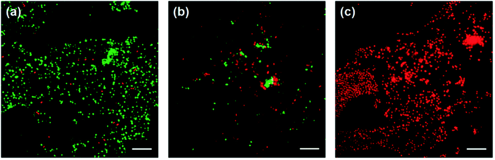 | ||
| Fig. 5 Vitality staining of bacterial cultures. Fluorescence microscopy images of LIVE/DEAD stains of E. coli cultures not subjected to thermal treatment (a), after thermal treatment for 2 h in the presence of LiTaO3 (5–10 μm) (b), and after 1 h thermal treatment in the presence of LiTaO3 (<5 μm) (c). Reprinted with permission from ref. 31. Copyright (2012) American Chemical Society. | ||
In 2015 Benke et al.32 reported an enhanced disinfection process, which was assisted with the use of palladium nanoparticles on the pyroelectric particle surfaces. Barium titanate (BaTiO3) nanoparticles of 100 nm in size where coated with 40 nm palladium (Pd) nanoparticles. The mechanism is shown in Fig. 6(a) where again heating and cooling cycles lead to free surface charges being produced on the polarised material surface, which can contribute to Red–Ox reactions. Due to the small particle size, the surface potential generated by the BaTiO3 nanoparticles from pyroelectric effect is lower than the voltage needed for reactive oxygen species generation (see eqn (5)). However, in their energy band model, which is shown in Fig. 6(b), the pyroelectric BaTiO3 particle was assumed to be a p-type semiconductor and the Fermi level of BaTiO3 was at the mid-band gap (Fig. 6(b), upper left). The band of BaTiO3 is thought to tilt due to the internal electric field that is generated by a change in temperature and the pyroelectric effect (Fig. 6(b), upper right). As the Pd nanoparticles are in contact with the BaTiO3 particles, electrons (e−) are able to transfer into the Pd particles and the holes (h+) into the valence band of BaTiO3 to become a source of ˙OH radicals (Fig. 6(b), lower image). Hence Benke et al. assumed that the ˙OH generating reaction, which improved disinfection, was strongly dependent on the enhanced charge transfer between the Pd and BaTiO3 nanoparticles.
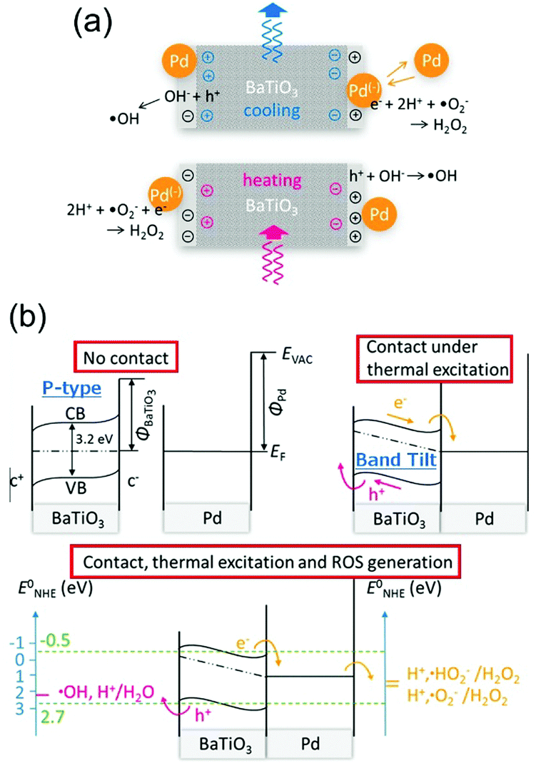 | ||
| Fig. 6 (a) Schematic of reactive oxygen species (ROS) generation driven by the pyro-electro-chemical effect assisted by palladium nanoparticles.32 (b) Energy level diagrams and reactive oxygen species (ROS)-generating charge transfer due to thermal excitation of pyroelectric barium titanate. Redox potentials between palladium nanoparticles, barium titanate, and neutral aqueous surrounding relative to standard hydrogen electrode are compared for selected species. Adapted with permission from ref. 32. Copyright (2015) American Chemical Society. | ||
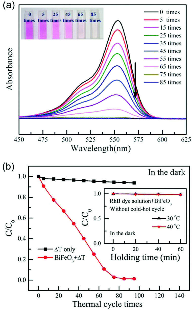 | ||
| Fig. 7 (a) UV-vis spectra of the Rhodamine B (RhB) solution with increasing numbers of thermal cycles (from 27 °C to 38 °C) using BiFeO3 nanoparticles as the pyro-electro-catalyst. The inset shows the colour change of the RhB dye solution after increasing number of cold–hot cycles. (b) Pyro-electro-catalytic RhB dye degradation after increasing number of thermal cycles (from 27 °C to 38 °C) with or without BiFeO3 nanoparticle pyro-electro-catalyst. For comparison, the inset shows the RhB dye degradation with BiFeO3 catalyst after being held at a constant temperature. Reproduced from ref. 33 with permission from The Royal Society of Chemistry. | ||
 | ||
| Fig. 8 Hybrid pyro- and tribo-electric energy cell for electro-catalytic oxidation and degradation of methyl orange. (a) Schematic of self-powered electro-degradation of methyl orange (MO). (b) Degradation and colour change of the methyl orange solution with time. Reprinted with permission from ref. 37. Copyright (2013) American Chemical Society. | ||
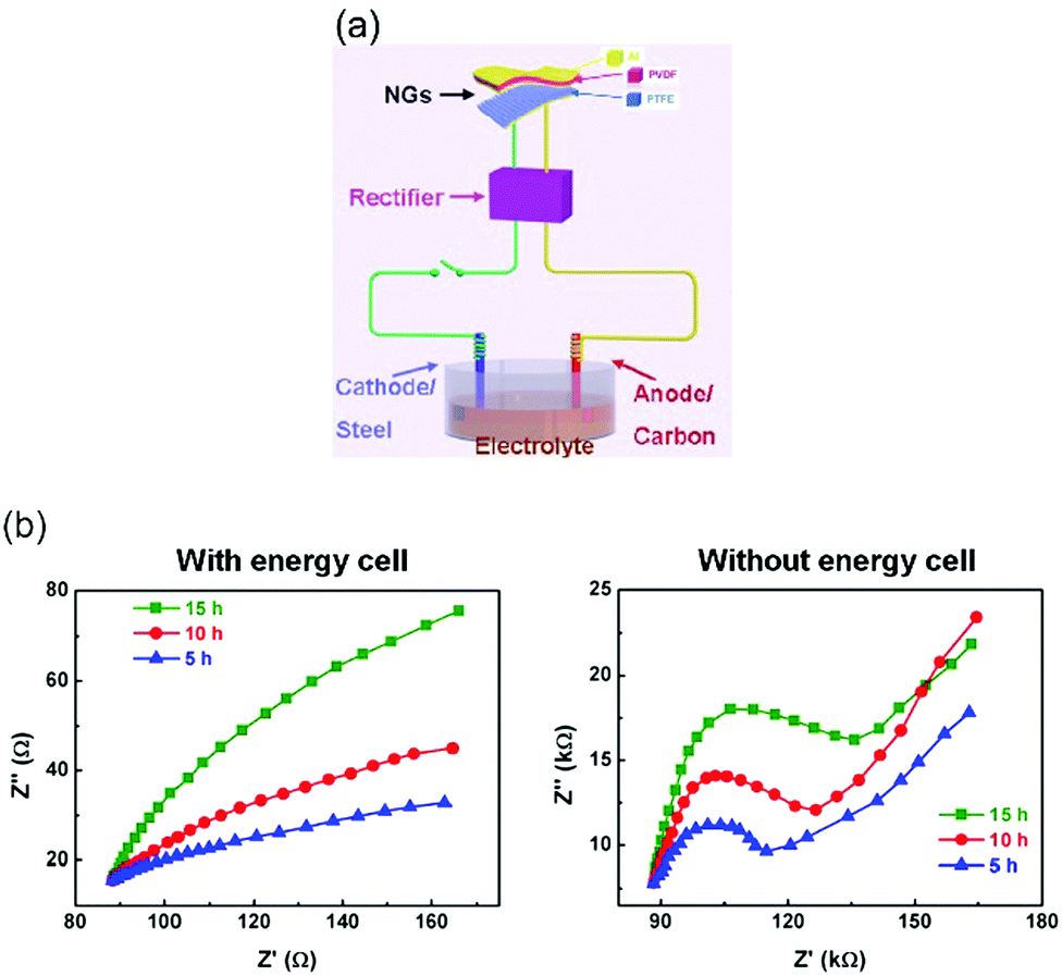 | ||
| Fig. 9 (a) Schematic of hybrid self-powered cathodic protection system and (b) Nyquist diagrams of carbon steel electrodes after corrosion with and without hybrid the nanogenerator (energy cell). Adapted with permission from ref. 38. Copyright (2015) American Chemical Society. | ||
Pyroelectric materials also have the potential to simply harvest temperature changes associated with exothermic or endothermic reactions. Industrial and lab-scale chemical processes can generate a large amount of waste heat and the low-grade nature of the heat and ease of dissipation makes is difficult to be harvested. Zhao et al. fabricated a flexible pyroelectric energy harvester, which consisted of ferroelectric PVDF sandwiched between two multi-walled carbon nanotubes electrodes. This system was demonstrated to harvest sufficient waste heat from chemical exothermic process for low power electronics.39
2.3 Pyro-electric ice-formation and other applications
Beyond the reduction–oxidation reactions that have been described above, pyroelectric materials have also been used to control surface ice-formation, indicating potential use of charges generated during heating or cooling to control freezing behaviour. Control of the freezing temperature of super-cooled water is important in areas such as cell and tissue cryo-preservation and prevention of crop freezing. Electro-freezing40 using electric fields on charged surfaces has been exploited for the formation of ice-like nuclei and enhance the freezing of super-cooled water. The use of electro-freezing on metallic surfaces is difficult since its electrical conductivity isolates the net effect of the electric field. Ehre et al. reported the use of pyroelectric materials to isolate the electric field since they are insulators (dielectrics) and the polarity of the surface can be manipulated by changing the polarisation direction.41 Positively charged surfaces of pyroelectric LiTaO3 crystals and SrTiO3 thin films were shown to promote ice nucleation, while negatively charged surfaces were shown to inhibit ice nucleation and thereby reduce the freezing temperature. Fig. 10 shows optical microscopy images of water droplets and condensation on amorphous (top) and quasi-amorphous (bottom) films of SrTiO3 at a variety of temperatures. The water was observed to freeze at a higher temperature of −4 °C on the quasi-amorphous (pyroelectric) film compared to −12 °C on the amorphous (nonpolar) film. In addition, it has been reported that polyvinylidene fluoride (PVDF) can be used as an ice repellent coating42 and the strength of ice repellency can be increased by increasing the polarisation of the coating. Pyroelectricity has also been recently observed in nonpolar, centrosymmetric crystals of amino acids43,44 which originates from the thin polar layer of hydrated α-glycine near its surface and this influences its freeing characteristics. With amino acid crystals, Ehre et al. found that ice nucleation can be close to 0 °C due to a relatively large pyroelectric effect.45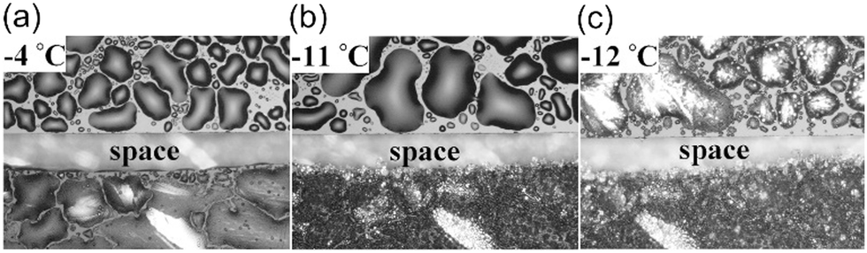 | ||
| Fig. 10 Freeze point control using pyroelectric materials. Optical microscopy images of water drops condensed on non-pyroelectric amorphous (top) and pyroelectric quasi-amorphous (bottom) films of SrTiO3 at various temperatures. Water freezes at −4 °C on the quasi-amorphous (pyroelectric) film and at −12 °C on the amorphous (nonpolar) film. From ref. 41. Reprinted with permission from AAAS. | ||
In a similar approach to tuning ice nucleation, pyroelectric materials have been used to pattern polymer films; and the reader is referred to a review by Coppola et al.46 Xi et al. used LiNbO3 (LN) to generate parallel charge patterns, and achieved self-assembly and patterning of a thin polymer film through an electro-hydrodynamic process.47 By placing a hot polydimethylsiloxane (PDMS) stamp on a LiNbO3 surface, it was possible to induce the formation of local pyroelectric charge by transferring heat from a patterned PDMS stamp to the pyroelectric LiNbO3. The electrostatic stress generated from the patterned surface charge was able to drive the assembly of the thin polymer film into microarrays. A schematic of the process is shown in Fig. 11 where the hot stamp generates surface charges for assembly of solvents (a to b) or immersion in water for patterning (c to e). In addition, periodically poled pyroelectric crystals can lead to electrowetting effect and form liquid lenses on a surface in an electrodes-less and circuit-less manner.48 This provides scope for thermal scavenging for freezing/wetting, materials assembly and fabrication, and examples of harvesting for materials synthesis is described in the section on tribo-electric harvesting.
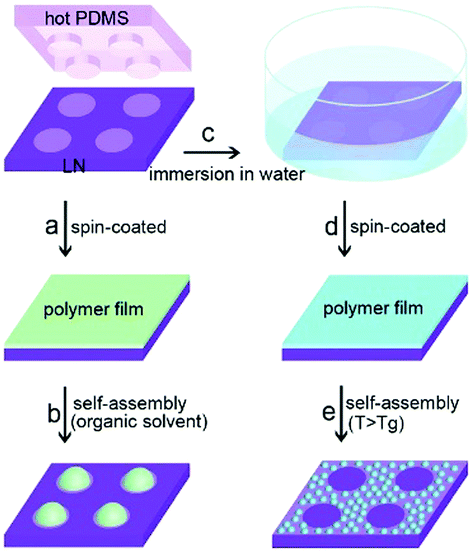 | ||
| Fig. 11 Schematic showing the procedure of electrostatic charge patterning using hot micro-contact printing on LiNbO3 (LN) substrate followed by self-assembly of thin polymer film. Reproduced from ref. 47 with permission from The Royal Society of Chemistry. | ||
3. Piezo-electro-chemical effect
The direct conversion of mechanical energy into chemical energy, known as the piezo-electro-chemical (PZEC) effect, was first reported in 2010 by Hong et al.49 In this work, the piezoelectric properties of the materials were used to achieve water splitting for hydrogen generation. Following this work, the piezo-electro-chemical effect was utilised for a number of other applications, such as water purification and self-charging power cells, either as the sole harvesting mechanism or used in a hybrid system to enhance the primary energy conversion. These approaches will now be described.3.1 Piezo-electro-chemical water splitting
Hong et al. used piezoelectric ZnO microfibres and BaTiO3 micro-dendrites immersed in water to produce H2 by harvesting ultrasonic vibrations.49Fig. 12 shows the piezoelectric charges developed on a ZnO fibre surface as a consequence of being mechanically excited by ultrasonic waves; the conditions are summarised in Table 1. The resulting mechanical strain of the ZnO fibre changes its polarisation to create free surface charges that can contribute to Red–Ox reactions on the positive and negative surfaces of the piezoelectric fibre. This is shown in Fig. 12 where bending from ultrasonic excitation is thought to produce negative charges on the tensile face and positive on the compressive face to contribute to Red–Ox reactions.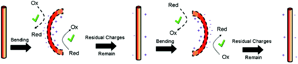 | ||
| Fig. 12 Schematic of piezoelectric charges and Red–Ox reactions on a ZnO fiber surface through bending by ultrasonic vibration. Reprinted with permission from ref. 49. Copyright (2010) American Chemical Society. | ||
To achieve water splitting the developed potential must be greater than the redox potential of water (eqn (1) and (2)) and potentials lower than 1.23 V will not participate in reactions to form H2 and O2. Starr et al.50 used a single-crystal ferroelectric Pb(Mg/3Nb2/3)O3–32PbTiO3 (PMN–PT) cantilever in a sealed chamber that was strained using a computer controlled vibrator and linear actuator. Fig. 13 shows the experimental set up where deformation of the piezoelectric cantilever was achieved remotely via two encapsulated magnetic materials placed at the tip of both the cantilever beam and driving lever arm.
 | ||
| Fig. 13 Piezoelectric water splitting experimental setup: (a) flexible substrate for strain induction, a piezoelectric element for generation of piezoelectric potential and charge, and a clamp for securing the cantilever base. (b) Experimental setup and reaction apparatus used for studying piezo-catalysed hydrogen evolution from water. Reprinted from ref. 50, Copyright (2015), with permission from Elsevier. | ||
Following this work, Starr provided general guidance on approaches to exploit the piezoelectric properties of materials to initiate surface reactions.51,52 Their fundamental analysis indicates that a high piezoelectric coupling coefficient and a low electrical conductivity are desired for enabling high electrochemical activity. Materials that could be used for such applications are PMN–PT, ZnO, BaTiO3 and PbTiO3; and many of the materials are shown in Fig. 2 for the pyroelectric analysis of Xie et al. The correlation between piezoelectric and pyroelectric properties is unsurprising since both originate from a change in polarisation with stress or temperature, respectively;53 see Fig. 1. In an attempt to achieve a more flexible and inexpensive harvesting design that could utilize low vibration frequencies, rather than high frequency ultrasound, Zhang et al. proposed an indirect piezo-electro-chemical process for water splitting.54 The device consisted of a piezoelectric bimorph cantilever and a water electrolysis system; the electrical output produced by mechanical vibrations was rectified and connected to an electrolyte to split water into hydrogen and oxygen. This design offered more flexibility and a high output voltage (approximately 12 V, see Table 1). The hydrogen production rate was 10−8 mol min−1 and approaches to enhance the production range include using a piezoelectric material with a higher piezoelectric coefficient (dij) and increasing the conductive ion concentration of the NaHSO4 electrolyte solution. Other factors can include increasing area (A) and level of applied stress (σ); since Q = dij·A·σ.
The piezoelectric properties of materials have also been used in combination with the more widely investigated photo-electro-chemical (PEC) water splitting to combine vibration and solar harvesting. To overcome the challenges of photo-electro-chemical water splitting, such as the limited absorption of visible light, Tan et al. fabricated a piezoelectric-photo-electro-chemical hybrid device that combined harvesting from both light and vibration using piezoelectric ZnO nanorods on one-dimensional nanowire conductors. This multiple-energy-source powered system was based on a metal–semiconductor branched hetero-structure of Ag/Ag2S–ZnO/ZnS that was partially encapsulated with PDMS for piezoelectric harvesting, while the exposed part acted as a catalyst to enhance the photo-electro-chemical performance of the ZnO nanorods. The system was initially characterised separately under UV-vis irradiation and under ultrasonic vibrations, as in Fig. 14a.55 Under simultaneous application of UV-vis light and vibration, as in Fig. 14b, the generation of piezoelectric charge and charge transfer between the active electrode and Pt electrode generated a voltage bias, as in Fig. 14b, which improved the photocurrent density from 8 mA m−2 (no vibration) to 22 mA m−2 (with vibration). The system was also used to enhance photo-electric-chemical degradation of methyl orange for water treatment. Yang et al. have utilised the polarisation of piezoelectric BaTiO3 to enhance photo-electro-chemical (PEC) water splitting.56 An enhanced performance of PEC photo-anodes was reported due to ferroelectric polarisation-enhanced band engineering of TiO2/BaTiO3 core/shell nanowires.
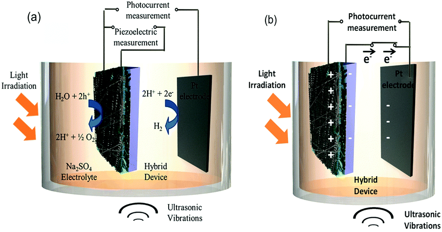 | ||
| Fig. 14 Operation of the hybrid device (a) Individual piezoelectric and photocurrent measurement (b) Charge transfer during deformation of the piezoelectric and photo-catalytic electrode under ultrasonic vibration and light irradiation. Reprinted with permission from ref. 55. Copyright (2015) American Chemical Society. | ||
3.2 Piezo-electro-catalytic degradation of organic pollutants
In addition to harvesting mechanical vibration for water splitting, the piezoelectric effect has been used for degradation of organics in water. After exploiting the piezoelectric effect for water splitting, Hong et al. explored a similar approach for Azo Dye decolourisation in aqueous solutions57 and for the degradation of Acid Orange 7 (AO7), the origins of the electron–hole pairs were from strained piezoelectric BaTiO3 micro-dendrites. By harvesting ultrasonic vibrations the AO7 dye was degraded by nearly 80% after subjecting the material to 90 min of vibration. Using the same mechanism, Lin et al. used the piezoelectric properties of Pb(Zr0.52Ti0.48)O3 (PZT) fibres to harvest mechanical vibrations and further improve efficiency due to the large amount of electrical charge generated by the highly piezo-active PZT material.58 In 2017, Lv et al. focused their work on investigating the piezo-electro-chemical effect to degrade AO7 using BaTiO3 in the presence of metal ions, since calcium, magnesium, aluminium, iron and copper are frequently found in waste water.59 The fundamentals of the piezo-photo-chemical mechanism have been described by Z. L. Wang.60 When the piezoelectric is subjected to a periodically applied strain during vibration the photo-generated electrons and holes migrate to the surface in opposite directions under the influence of the electric field produced by the piezoelectric effect; thereby achieving a higher efficiency due to suppression of electron–hole recombination.Xue et al. used ZnO nanowires that combine the properties of a piezoelectric and a semiconductor. The photo-catalytic activity of ZnO nanowires was enhanced by the piezoelectric and electric field driven separation of the photo-generated carriers for the degradation of methylene blue (MB).61 The working mechanism for the piezo-photo-catalytic activity of ZnO nanowires in the work of Xue et al. is shown in Fig. 15 where Fig. 15a shows the woven ZnO nanowires/carbon fibres (CFs) without an applied force or UV irradiation. When subjected to UV light, as in Fig. 15b, there is a transition of electrons from the valence band to the conduction band, leaving an equal number of holes. When a periodic force is simultaneously applied to the ZnO nanowires/CFs, as in Fig. 15c, there is a relative motion between neighbouring ZnO nanowires that results in bending of the ZnO nanowires which produces positive and negative piezoelectric potentials across their width. The generated piezoelectric field then drives electrons and holes to migrate to the surface in opposite directions and the recombination of electrons and holes is therefore reduced. The electrons (e−) react with dissolved oxygen molecules to yield superoxide radical anions (˙O2−), and the holes (h+) are ultimately trapped by H2O at the surface to yield ˙OH− radicals, Fig. 15d. The hydroxyl radicals can oxidize MB in aqueous solution, generating non-toxic CO2 and H2O. The photo-catalytic efficiency of ZnO nanowires was thought to be enhanced by the piezoelectric field and reduced recombination of photo-generated carriers.
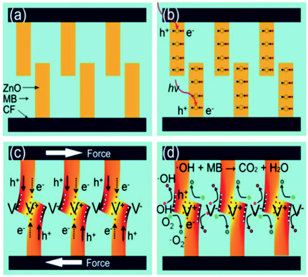 | ||
| Fig. 15 Mechanism for piezo-photo-catalytic activity of ZnO nanowires. (a) ZnO nanowires/carbon fibres (CFs) without an applied force or UV irradiation. (b) UV illumination of ZnO leads to transition of electrons from the valence band to the conduction band, and equal number of holes. (c) When a force is applied, bending of ZnO produces positive and negative piezoelectric potentials across their width. The piezoelectric field drives electrons and holes to the surface in opposite directions. (d) Electrons (e−) react with dissolved oxygen molecules to yield superoxide radical anions (˙O2−) and holes (h+) are trapped by H2O at the surface to yield ˙OH− radicals. The hydroxyl radicals oxidize methylene blue (MB) in aqueous solution. Reprinted from ref. 61, Copyright (2015), with permission from Elsevier. | ||
To exploit the same combination of piezoelectric and semiconducting properties, Lo et al. used ZnSnO362 and Wang et al. used Zn1−xSnO3.63Fig. 16 shows the increased rate of degradation of methylene blue by applying both stress and UV on piezoelectric ZnSnO3 nanowires; see the blue piezo-photo-catalysis curve.62
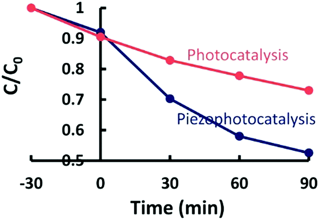 | ||
| Fig. 16 Self-photo-degradation of methylene blue (MB) and photo-catalytic activity of piezoelectric ZnSnO3 nanowires with and without applied stresses and UV irradiation. Reprinted with permission from ref. 62. Copyright (2015) American Chemical Society. | ||
To further improve the piezo-photo-catalytic effect Hong et al. used CuS/ZnO hetero-structure nanowire arrays that were subjected to a combination of UV and ultrasonic irradiation to degrade MB.64 Sun et al. used Ag2O/ZnO nano-tetrapods, Zhang et al. used Ag/ZnO and Li et al. used Ag2O/BaTiO3.38,65,66 Again, the higher efficiency and speed of degradation was attributed to the coupling between the built-in electric field of the hetero-structure and the piezoelectric field of ZnO under strain that enhanced electron–hole separation and migration in opposite directions. This is demonstrated in Fig. 17, where the ZnO that is on a stainless steel mesh is mechanically deformed due to the application of ultrasound and this leads to an electric field across the wire. Since the wire is also photo-excited by solar radiation, electrons and holes are separated due to the applied field towards opposite directions and drive the surface reactions, Fig. 17(a). Fig. 17(b) shows the effect that the field has on the energy bands that separate the photo-excited electrons and holes in opposite directions.
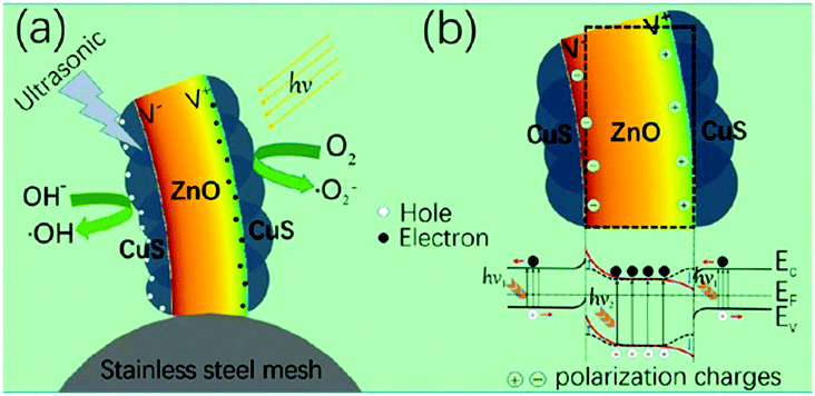 | ||
| Fig. 17 (a) Schematic of piezo-photo-catalytic process of CuS/ZnO nanowires on stainless steel mesh under combined solar and ultrasonic irradiation. (b) Schematic of energy band diagram of CuS/ZnO heterostructure under both solar and ultrasonic irradiation. Reprinted with permission from ref. 64. Copyright (2016) American Chemical Society. | ||
Further information on the influence of ferroelectricity and piezoelectricity on photo-catalytic activity and surface chemistry, in the absence of vibration, can be found in a recent review67 and a number of key papers by Dunn et al.68–74 Since ferroelectric materials are both piezoelectric and pyroelectric there is significant scope for further efforts to harvest thermal and mechanical energy in combination with light for enhancing electro-chemical reactions.
3.3 Piezo-electro-chemical self-charging of power cells
Energy generation and energy storage are two distinct processes and are usually accomplished separately. However, in 2012 Xue et al. introduced a new mechanism where harvested mechanical energy was directly stored as chemical energy.75 The polyethylene separator of a conventional lithium battery was replaced with a piezoelectric PVDF polymer. When the device was subjected to a compressive strain, the piezoelectric induced electric field of the PVDF separator acted to drive electrical charges from the cathode to the anode, thereby charging the power cell. Later, the same group fabricated a novel integrated self-charging power cell (SCPC) that combined a CuO anode with a PVDF separator in the form of CuO/PVDF nano-arrays. The high efficiency of the cell was attributed to the intimate contact and large interface area between the anode and separator.76 This is shown in Fig. 18 and when a compressive stress is applied, the PVDF creates a positive piezo-potential at the cathode and a negative piezo-potential at the anode (Fig. 18(b)). Lithium ions then migrate in the electrolyte from the cathode to anode under the generated electric field, leading to charging reactions at the electrodes (Fig. 18(c)) until chemical equilibrium of the two electrodes is re-established and the self-charging process ceases. When the compressive stress is released, the piezoelectric field of the PVDF disappears, which breaks the electrostatic equilibrium, and residual lithium ions diffuse back to the cathode; see Fig. 18(c). In such a system rectification is not required since it is operated in compression only, so that the polarity of the system is maintained; although care would need to be taken to ensure tensile loads are not experienced by the system.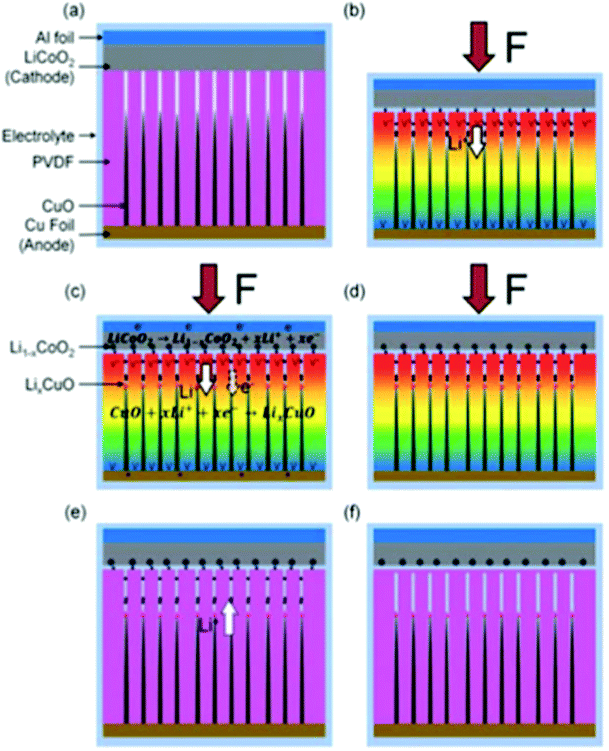 | ||
| Fig. 18 (a) Schematic of self-charging power cell in discharged state. (b) Under a compressive stress the piezoelectric PVDF creates a piezo-potential with a positive potential at the cathode and a negative piezo-potential at the anode. (c) Under the internal piezoelectric field, lithium ions migrate in the electrolyte from cathode to anode, leading to charging reactions at the electrodes. (d) Chemical equilibrium of the two electrodes is re-established and self-charging ceases. (e) When the compressive force is released, the piezoelectric field disappears, which breaks the electrostatic equilibrium and residual lithium ions diffuse back to the cathode. (f) The electro-chemical system reaches a new equilibrium, and self-charging is complete. Reproduced from ref. 76 with permission of The Royal Society of Chemistry. | ||
Approaches to further improve the energy conversion and storage efficiency include the use of a composite or porous separator. Xing et al. used a mesoporous PVDF separator that lowered the charge transfer resistance.78 Highly porous PVDF, PVDF–PZT nano-composites and PVDF–ZnO composites have also been examined.77,79,80Fig. 19 shows a typical device architecture with a porous PVDF separator, graphite anode, and LiCoO2 cathode.
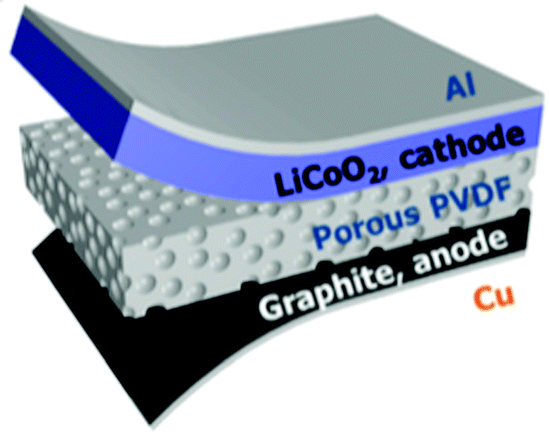 | ||
| Fig. 19 Schematic diagram of a self-charging power cell (SCPC) consisting of LiCoO2 as the cathode, artificial graphite as the anode, and a porous PVDF piezo-separator. Reproduced from ref. 77 with permission of The Royal Society of Chemistry. | ||
It is desirable to improve the integration level and minimise energy loss in the power-management circuits between energy harvesting and storage devices. Song et al., Ramadoss et al., and Wang et al. integrated a piezoelectric separator in a supercapacitor80–82 and to further improve the performance Parida et al. used a poly(vinylidene fluoride)-trifluoroethylene (P(VDF-TrFE)) foam as a piezoelectric separator and designed a double layer capacitor with fast absorption and desorption of ions at the carbon nanotube electrodes.83 A different approach to use the piezoelectric effect for enhanced charge storage was proposed by Lee et al. The mechanical stress from the expansion of silicon during lithiation was transferred via a conductive carbon nanotube (CNT) based matrix to ferroelectric BaTiO3 particles so that a piezoelectric potential was generated.84 This is shown in Fig. 20, where the silicon and BaTiO3 particles are dispersed in a CNT matrix (Fig. 20(a)). Lithiation of the silicon nanoparticles results in a volume increase that applies pressure to the BaTiO3 nanoparticles to create a piezoelectric potential (Fig. 20(b)) that enhances the mobility of the lithium ions in the subsequent discharging and charging processes.
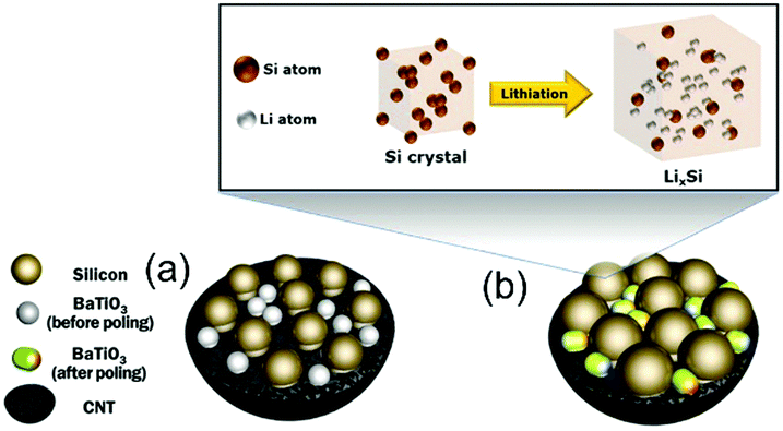 | ||
| Fig. 20 Schematic of microstructural changes in the Si/carbon nanotube(CNT)/BaTiO3 nanocomposite anode during lithiation. (a) Si and BaTiO3 particles are dispersed and attached to the CNT. (b) Lithiation of Si results in a large increase in volume, pressurising BaTiO3 nanoparticles to create a piezoelectric potential. Adapted with permission from ref. 84. Copyright (2016) American Chemical Society. | ||
A particularly novel approach by Kim et al. does not use the piezoelectric effect, but is based on stress driven electro-chemical effects.85 In this design different stress states are induced by bending partially lithium-alloyed silicon electrodes which creates a potential difference between the electrodes. Fig. 21 shows the working mechanism. In the initial stress-free condition, the two electrodes are at an iso-potential (Fig. 21(I)). Bending of the device generates tension in the lower electrode and compression in the upper electrode in Fig. 21(II). The asymmetric stress state creates a chemical potential difference that drives Li+ migration from the compressive electrode to the tensile electrode through the electrolyte (Fig. 21(III)). In order to maintain charge neutrality, electrons flow in the outer circuit from the compressive and to the tensile electrodes, thereby generating electrical power. The Li+ migration continues until the potential difference vanishes, and a new equilibrium state on the two electrodes with different lithium concentrations are achieved (Fig. 21(IV)). When the external stress is removed by unbending the device, the chemical potential shifts on the electrodes and the difference in lithium concentration between the electrodes drives Li+ migration in the opposite direction (Fig. 21, back to I), thereby discharging the device. This provides an interesting approach to harvest mechanical motion for electro-chemical based energy generation, which could be enhanced by coupling to piezoelectric effects to generate an additional electric field to enhance ion migration.
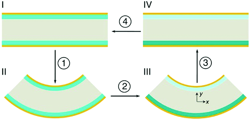 | ||
| Fig. 21 Schematic of the cross-section of the device in operation using partially lithium-alloyed silicon electrodes. Reproduced from Kim et al.85 with permission from Nature Publishing Group (Copyright 2016). | ||
3.4 Other piezo-electro-chemical applications
Noris-Suarez have reported bone healing due to piezoelectricity.86 Bone healing and growth are controlled by the rate of deposition of hydroxyapatite (HA) and their work showed that the piezoelectric dipoles produced by deformed collagen can produce the necessary precipitation of HA. Therefore there is scope to harvest biomechanical motion for enhanced bone growth. Lang et al.87 demonstrated that HA is both piezoelectric and pyroelectric indicating potential for harvesting human motion and temperature changes; the reader is referred to a review on the topic by Baxter et al.88 A biomimetic approach was used by Soroushian et al. who investigated self-healing structures that were able redistribute their structural mass in response to dynamic loads.89 In their work the piezoelectric effect was used to convert dynamic mechanical energy applied to a structure into electrical energy that was able to drive an electro-chemical self-healing phenomena within a solid electrolyte. Zhang et al. also used PVDF to use piezoelectric energy to indirectly power cathodic protection38 and the output of the fabricated device was used to protect metal surfaces from the chemical corrosion, see Fig. 9. Touach et al.90 used lithium niobate (LiNbO3) as a ferroelectric and photo-catalyst material as a cathode catalyst for wastewater-fed single-chamber microbial fuel cells (MFCs); microbial cells are also discussed with regard to thermoelectrics (Section 6).4. Tribo-electro-chemical effects
Compared with the piezo- and pyro-electric based energy harvesters, the utilisation of the triboelectric effect in a triboelectric nanogenerator (TENG) to scavenge mechanical energy is a relatively new approach in the field of energy harvesting, and was first reported in 2012 by Z. L. Wang's group.91 The mechanism of charge generation exploits the intrinsic ability of materials in different positions of the triboelectric series to gain or lose charge when they make contact with each other. The triboelectric charges that are generated on the surface of the two materials can be regarded as a combination of tribo-electrification and electrostatic induction. TENGs typically have four basic working modes, which are shown in Fig. 22.8 The generation of charge relies on contact and separation cycles between two different materials and the modes of operation can involve rubbing or contact between two materials under vertical (Fig. 22a) or lateral sliding (Fig. 22b), with two electrodes to collect the charge. Single-electrode configurations can also be employed, as seen in Fig. 22c, and freestanding moving objects without an electric connection can be utilised; see Fig. 22d. In all of the potential modes of operation, the movement of the free electrons enables the generation of a current that flows in an external circuit, which can be an electro-chemical system, storage capacitor or an electrical load.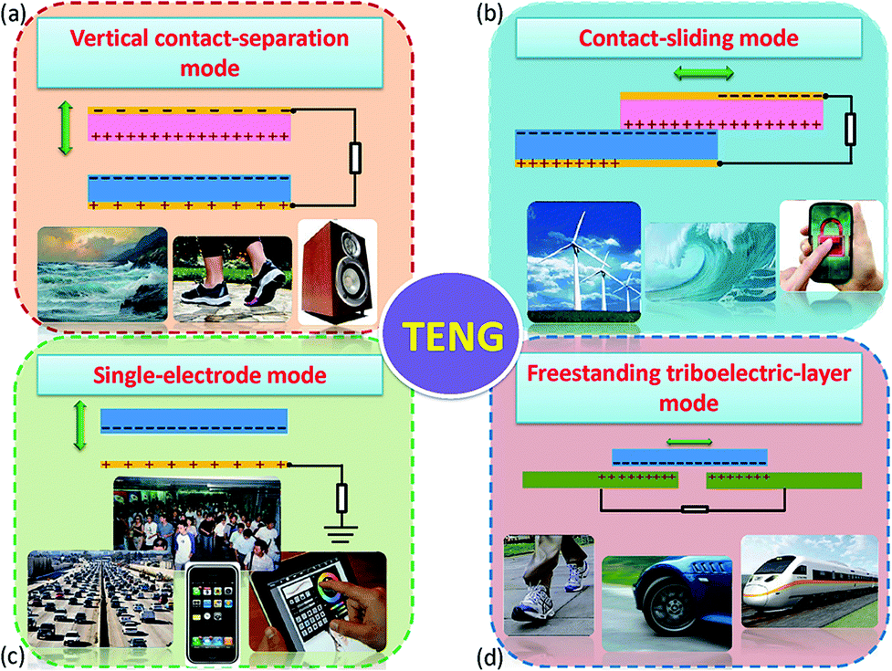 | ||
| Fig. 22 The four working modes of the triboelectric nanogenerators (TENGs). (a) vertical contact-separation mode, (b) lateral-sliding mode, (c) single-electrode mode, and (D) freestanding triboelectric-layer mode. Reproduced from ref. 8. with permission from The Royal Society of Chemistry. | ||
TENG devices are being rapidly developed with increasing efficiency in terms of their ability to convert mechanical energy into electricity. The power densities and instantaneous energy conversion efficiency for a single device has been reported to be as high as 500 W m−2 and 70%.92,93 Owing to their high power density, high efficiency, small volume, light-weight nature and low fabrication cost, TENGs are attracting potential in harvesting ‘blue energy’ from wave power.94
The energy that is harvested from ambient environments by TENGs varies significantly and can be periodic, random and time-dependent, which results in an alternating current (AC). Moreover, the magnitude of the pulsed voltage in TENGs is relatively high (typically 2 V to 1.3 kV, see Table 1) while the current remains relatively low (85 nA to 13 mA, see Table 1) which often requires the use of a power management circuit. As a result, when TENGs are coupled to electro-chemical processes, they can act as the power source either by directly powering the electro-chemical system with a pulsed output that is rectified to maintain the polarity of the output or a combination of transformer (to step down the voltage) and rectifier that is used to charge an integrated capacitor/battery before supplying the electro-chemical system with a direct current (DC) electrical output. As a result, integrated TENG-controlled electro-chemical systems often consist of a triboelectric generator, an AC/unipolar signal converter with a rectifier and/or transformer and the functional electro-chemical unit. Cao et al. have provided an excellent review on triboelectric nano-generators and electro-chemical systems.95 Here we will concentrate on the introduction to the mechanisms of triboelectric generation for controlling electro-chemical processes and describe recent achievements in electro-chemical processes controlled by TENGs.
4.1 Tribo-electro-chemical water splitting
As discussed in Section 2.1, water splitting can be electrically triggered when the potential difference between the anode and cathode is greater than 1.23 V (eqn (1) and (2)). Triboelectric nanogenerators have been used to harvest ambient sources of mechanical energy and supply electrical power to achieve electro-chemical water splitting without the need for an external power source.96–98 Yu et al.99 fabricated a wind-driven TENG to supply a bias voltage after rectification between a platinum counter electrode and a working electrode with a 3-D structure based on TiO2 nanowires and graphite fibres. The combined system provided enhanced photo-catalytic activity and generated 4.87 mmol (h g)−1 H2 with the aid of solar illumination and wind, this was almost three times higher than a TiO2@MoS2 catalyst under a visible light source.100Fig. 23(a) shows the system with the wind powered TENG, and rectification bridge to maintain electron flow in one direction. Under the application of wind and UV light, hydrogen generation was observed on the counter electrode. However, due to the relatively low current density on the TiO2 nanowire/graphite fibre electrode and the resistance mismatch between the TENG, electrical load and electrochemical system, Li et al.101 combined both electrolysis and photo-electro-chemical (PEC) effects to improve H2 production and increase solar efficiency. Fig. 23(b) shows the system employed, that used a TENG driven by a linear motor to supply a potential across a photo-anode and counter electrode. A lithium-ion battery, not shown in Fig. 23(b), was used to provide a stable DC output (1.5 V) after being charged by a TENG for 42 min using rectification and transformation, where a series of loads of different resistance were chosen to match the electrical impedance in the external circuit. A similar photo-anode approach was used by Pu et al. to achieve enhanced photo-activity by a surface plasmonic resonant effect.102 This anode consisted of Au nanoparticle decorated TiO2 arrays on fluorine doped in tin oxide (FTO) conductive glass, as shown in Fig. 23(c). Au nanoparticles were used to localize the optical energy due to the surface plasmonic resonance and the interaction between this electric-field amplification and TiO2 promoted photon absorption. In addition, the gold nanoparticles also act as a photosensitiser when the wavelength of the surface plasmonic resonant matches the optical band gap of TiO2, therefore hot electron injection from Au to the TiO2 conduction band was enhanced under visible light.102 This coupled TENG-photo-electro-chemical (PEC) hybrid cell provided a route to split water by converting mechanical and solar energy into chemical energy. Interestingly, the generated H2 and O2 on the anode and cathode from water splitting has also been employed to pressurise a drug solution in a reservoir for an implantable drug-delivery system (iDDS);103 see Fig. 23(d) which shows the TENG, rectification, and the implantable drug delivery system. Yang et al.97 developed a hybrid energy cell that integrated a TENG, a thermoelectric cell and a solar cell that could simultaneously harvest mechanical, thermal and/or solar energies for water splitting; the specific application of thermoelectrics to electro-chemical systems will be described in more detail (Section 6).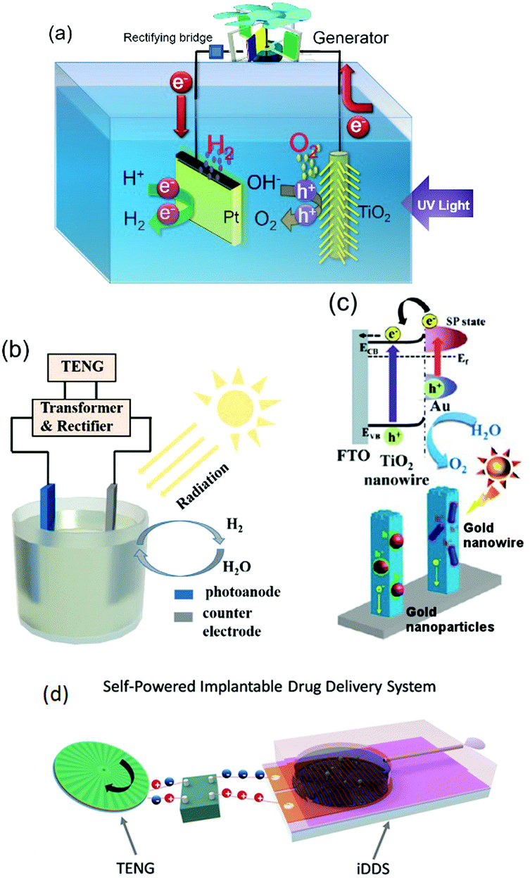 | ||
| Fig. 23 (a) Schematic of photo-electro-chemical water decomposition with bias voltage from a TENG. Reprinted from ref. 99. Copyright (2015) with permission from Elsevier. (b) Schematic of the TENG-photo-electro-chemical (PEC) hybrid cell. Reproduced with permission from ref. 101. Copyright 2017, John Wiley and Sons. (c) Charge transfer schematic of Au–TiO2 used in the TENG-PEC hybrid cell. Adapted with permission from ref. 102. Copyright (2013) American Chemical Society. (d) Schematic of the TENG-based implantable drug delivery system (iDDS). With permission from ref. 103. Copyright 2017, John Wiley and Sons. | ||
4.2 Tribo-electro-chemical degradation and wastewater treatment
The pyroelectric effect, which harvests temperature fluctuations, and the piezoelectric effect, that harvests vibrations, has been used for water treatment, as discussed in Sections 2.1.2 and 3.2 respectively. TENGs that harvest motion have also attracted interest as a form of self-powered electro-chemical wastewater treatment and SO2 removal as it is environmentally friendly and does not create toxic waste.37,104–109 Zheng et al.110 deployed a TENG to remove toxic organics in water; this included aniline (ANI) and N(p-C6H4Br)3 which was removed via an oxidation process; the performance of the self-powered treatment by a TENG was reported to be as effective as an electro-chemical workstation which requires a galvanostat as an external power source. Gao et al. fabricated a TENGs with either a multilayer-linkage configuration (rd-TENG in Fig. 24(a)111 or a rotary disc-structure112 which were used as a self-powered unit to drive a water treatment process). In both cases rectification of the TENG output was used to ensure a unipolar supply to the anode and cathode along with a transformer to reduce the operating voltage as the potential produced by a TENG is typically higher than other harvesting systems, see Table 1. The TENGs were used for the removal of highly toxic and carcinogenic organics by conversion to CO2; this included oligomers, azobenzene dye and 4-aminoazobenzene. The electric oxidation potentials were controlled via either the resistance of the external load or the numbers of the friction layers in the TENG device. In later work, the metal electrode was replaced with a carbon material manufactured from bean curd that was used to degrade methyl red.113 | ||
| Fig. 24 (a) Schematic of the multi-layer TENG driving electro-chemical degradation. Reprinted with permission from ref. 113. Copyright (2017) American Chemical Society. (b) (left) Schematic diagram of the Cu2+ and Rhodamine removing powered by TENG and (right) the corresponding circuit diagram of this self-powered electro-chemical recovery system. Reproduced with permission from ref. 115. Copyright 2016, John Wiley and Sons. (c) Operation of the electro-coagulation process. Reprinted from ref. 117. Copyright (2016) with permission from Elsevier. | ||
In addition to the above toxic chemical compounds, heavy metal ions (such as Cu, Ni and Cr) are another main component in wastewater, which can cause severe illness when they enter our food chain. One of the most promising ways for reducing heavy metal ions is electro-deposition where the heavy metal can be reduced and collected from the surface of the electrode.114 Chen et al.115 employed a TENG as a power source connected to a sewage treatment system, shown in the left of the Fig. 24(b). Using a NaCl solution as the electrolyte, toxic Rhodamine B was degraded into CO2, H2O, and N2 at the anode, while the heavy metal copper ions were electrodeposited at the cathode, see right of the Fig. 24(b). It was demonstrated that the removal efficiency of Rhodamine B and Cu2+ from a pulsed electrical output from a TENG harvester was better than that of a DC supply. Similar research on Cu2+ reduction was also reported by Yeh et al.116 who used a TENG operating in a freestanding mode (Fig. 22(d)) which was coupled to the anode and cathode to drive the electro-chemical reduction of Cu2+ ions on the surface of the cathode in an aqueous based solution. Other wastewater electro-chemical treatments, such as electro-coagulation, can be driven by TENGs as demonstrated by Jeon et al.117 In this case, wind energy was utilised to generate electrical power via a TENG to power an electro-coagulation unit. In their system, shown in Fig. 24(c), metal ions (Mn+, which are Al3+ in the work) were generated at the anode while OH− ions were generated at the cathode. Colloidal pollutants, such as algae and dyes, reacted with the insoluble metal hydroxide and produce flocs which form coagulated pollutants so that clean water could be collected from the top of the water treatment system.
Li et al.118 recently built an electro-chemical ramie fiber degumming system and wastewater treatment with a water-driven TENG. Raw ramie fibers are a common textile material and exist as fiber bundles where the individual fibers are bonded to each other In order to extract the individual cellulose fibers the harvesting system shown in Fig. 25(a) was constructed; the system consisted of (i) a TENG, power management (transformer/rectification circuit and capacitors) and reaction pond, (ii) a Ti/PbO2 anode and titanium cathode immersed in the reaction pond. Due to the potential difference produced by TENG, hydroxyl ions move towards the anode which make the gummy materials break away from the cellulose part of the fiber which are then readily dissolved in a hot alkaline solution; see Fig. 25(a, iii). The surface of the treated fiber with the TENG exhibited the most clean and smooth surface, as shown in (c) and (f) in Fig. 25(b). Furthermore, the degumming wastewater was also electro-chemically degraded using a TENG after finishing the fiber treatment.
 | ||
| Fig. 25 (a) Working principle of the triboelectric ramie fibre degumming and self-powered wastewater treatment, (b) SEM images of (i) raw ramie fibers and (ii) degummed ramie fibers without TENG and (iii) degummed ramie fibers with TENG. Scale bars are 20 μm. Photographs of (iv) raw ramie fiber and (v) degummed ramie fiber without TENG and (vi) degummed ramie fiber with TENG. Scale bars are 1.5 cm. Reprinted from ref. 118. Copyright (2016) with permission from Elsevier. | ||
4.3 Tribo-electro-chemical corrosion protection
Cathodic protection is a common technique for protecting metals from corrosion to increase service life of metallic components and reducing maintenance costs; this can be achieved by applying organic coatings or using an electro-chemical cell. In a typical electro-chemical protection procedure, the metal to be protected will have an ohmic-contact to the negative polarity of the external power source and an inert electrode will be connected to the positive pole. Both electrodes are then placed in the corrosion electrolyte to form an electrolytic cell so that the metal will be protected as the cathode. Inspired by preliminary work119–123 on the realisation of cathodic protection powered by TENG, recent efforts have been undertaken on optimising the triboelectric material,124 using a conductive polymer PPy (polypyrrole)125 or combining TENGs with the piezo- and pyro-electric effects to form hybrid systems38 to ensure the cathode is below the corrosion potential to prevent corrosion. Fig. 26 shows an example of wind driven TENG whose output is rectified and then connected to platinum counter electrode and carbon steel for cathodic protection.125 In addition, the triboelectric effect has also been adopted for anti-fouling applications, where the pulsed energy generated by a TENG is used to remove or prevent the accumulation and growth of organisms on both anode and cathode, as demonstrated by Feng et al.124 | ||
| Fig. 26 Device structure of the cathodic protection system powered by polypyrrole nanowire (PPy NW) based TENG driven by wind (W-TENG). Ref. 125 – published by permission of The Royal Society of Chemistry. | ||
4.4 Tribo-electro-chemical synthesis (electro-deposition and electro-oxidation)
Energy harvesting by TENGs has also been used for materials processing. Electro-deposition is a process that uses an electrical current to reduce cations of a desired material from a solution and coat the material as a thin film onto a conductive substrate surface. TENGs have been used by Zhu et al. to harvest ambient mechanical energy for a self-powered electro-deposition process.126 Due to the risk of oxidation or corrosion of the metallic TENG electrodes when exposed to a wet environment, a conducting polymer polypyrrole (PPy) was chosen as the electrode to fabricate an all-plastic based TENG that included an integrated PPy-based supercapacitor, thereby providing sustainable power.127 Wang128 has recently exploited TENGs to provide a pulsed rectified output to electro-chemically polymerise PPy for up to nine chemical reactors; see Fig. 27. Similarly, TENGs can also facilitate the oxidation process for preparation of mesoporous Al2O3.129 A cross-linked TENG was designed by Zheng et al.110 which could supply power to chemically synthesise polyaniline (PANI) via either oxidisation of PANI-OH or ANI in an H2SO4 aqueous solution. | ||
| Fig. 27 Schematic of the self-powered synthesis and reactor system. Reproduced with permission from ref. 128. Copyright 2016, John Wiley and Sons. | ||
4.5 Additional tribo-electro-chemical applications
Additional electro-chemical research based on the triboelectric effect has been undertaken in the application of the electro-chemical sensing107,130–135 and electro-chromic applications.136–142 Due to the different triboelectric polarity between Hg2+ and Au nanoparticles (Au NPs), Hg2+ can selectively bond to the surface of the Au NPs. Lin et al.132 exploited this effect to detect and measure the concentration of Hg2+ using a self-powered triboelectric nano-sensor. TENG powered electro-chemical sensors have been reported that could detect humidity,143 melamine144 and ultraviolet light.145,146 Furthermore, electro-chromic materials were able to interact with the electrical energy produced by a TENG to achieve a colour change or to fluoresce continuously and reversibly during electro-chemical oxidation and reduction. A number of research efforts136,139–141,147 have shown that TENGs can supply a sufficient electrical output to stimulate electro-chromic behaviour either in a cathode (colour change under a negative potential) or anode (colour change under a positive potential).5. Flexo-electric and electro-chemical effects
While the piezoelectric effect relates to the generation of charge in response to an applied strain, the flexoelectric effect involves the generation of charge due to the presence of a strain-gradient. Biomembranes exhibit flexoelectric effects and are the basic building units of many cells and cellular structures.148 The phospholipid molecules in most biomembranes are organised in a bilayer format, as shown in Fig. 28, and both artificial and natural cell membranes have been shown to exhibit direct flexoelectricity (current generation from curvature) and converse flexoelectricity (voltage-induced curvature changes).149–151 Phospholipid molecules include a hydrophilic phosphate head and a hydrophobic C–H chain, as shown in Fig. 28(a),152 which resembles a cone and has a dipole directed toward the apex. Under the application of electric field the bilayer membrane that has proteins with an intrinsic polarisation, pp, undergoes a splay deformation via the converse flexoelectric effect.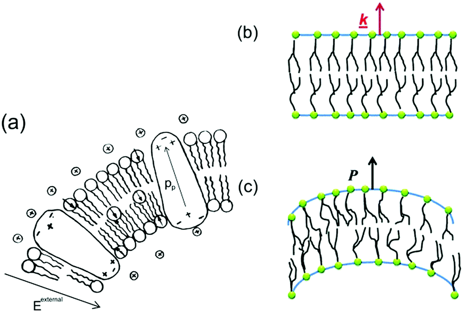 | ||
| Fig. 28 Flexo-electricity in biological membranes. (a) Schematic of bilayer lipid membrane under external electrical field, and globular proteins with an intrinsic polarisation. Ref. 152 – Copyright 1975, with permission of Springer. (b) Under planar conditions there is no polarisation and (c) Under bending the lower surface is in compression and the upper one in dilation, and an electric polarisation is generated. Reprinted figure with permission from ref. 153 Copyright (2013) by the American Physical Society. | ||
Direct flexoelectricity in biomembranes results from a curvature-induced polarisation of the liquid crystal membrane, in which the molecules (lipids, proteins) of the membrane are initially uniaxially orientated as shown in Fig. 28(b).153 In this flat bilayer membrane, the polarised cones are randomly directed, with no net polarisation. However, when subjected to bending, as in Fig. 28(c),153 a conformational change occurs that imposes a polar symmetry, so that on one side of the membrane the molecules move apart whereas on the other side they move closer together.154,155 The resulting polarisation (P) is:
| P = f·k·n | (6) |
Flexoelectricity has been found to have implications for mechano-sensitivity and mechano-transduction in living systems, including ion transport155,159 and the hearing mechanism in mammals.160–163 Petrov et al.159 proposed a model for ion transport in biological systems, as shown in Fig. 29, which demonstrates an ion pumping through a membrane. The driving force for ion transport is a flexoelectric electric field from a change in curvature of the bilayer membrane induced by Adenosine triphosphate (ATP) and ionic concentration gradients. The resulting curvature induces polarisation and creates a depolarising electric field that acts as a driving force for ion pumping. Similar flexoelectric effects are responsible for the main transduction component for sensing sound in mammals as inner hair cells consist of flexoelectric stereocilia that transform mechanical vibrations into electrical potentials that are sensed by the nervous system.160–163 The ability of biological membranes and cells to exhibit flexoelectric effects to achieve ion pumping and sensing could inspire new methods to harvest mechanical motion to drive ions in electro-chemical systems at the nano-scale.
 | ||
| Fig. 29 Ion pump model proposed by Petrov. The presence of ATP and ions lead to curvature of the phospholipid bilayer. This results in a flexoelectric polarisation and the electric field produced is the driving force for ion pumping. Membrane, ion and adenosine triphosphate (ATP) shown. Ref. 158 Reproduced by permission of The Royal Society of Chemistry. | ||
5.1 Flexo-electric energy harvesting
The potential of flexoelectricity in energy harvesting has been examined by several researchers. Significant enhancement of the piezoelectric coefficient of a piezoelectric nano-beam/ribbon due to flexoelectric effect has been reported.164,165 Pre-stretched buckled PZT ribbons show high strain gradients that provides charge in addition to the conventional piezoelectric effect.165Majdoub et al. used a continuum model to show that flexoelectricity can lead to an enhancement of electro-mechanical coupling of non-uniformly strained piezoelectric and non- piezoelectric nanostructures.164 For example, BaTiO3 nanobeams with a thickness of 5 nm experienced inhomogeneous strains almost five times larger than macro-scale BaTiO3 beams. Therefore in a narrow range of geometric dimensions, piezoelectric nanostructures can exhibit dramatically enhanced energy harvesting capability due to flexoelectric effects. For a PZT cantilever beam, the total harvested power increased by 100% for a 21 nm beam thickness under short circuit conditions and ∼200% increase could be achieved for tailored cross-sections.166 Deng et al. developed a continuum model for flexoelectric nano-scale energy harvesting for cantilever beams, as shown in Fig. 30(a) where the polarisation due to the resulting strain gradient is shown in Fig. 30(b). On bending an AC potential difference is generated across the electrodes on its upper and lower surfaces. The output power density and conversion efficiency increased significantly when the beam thickness was reduced from the micro- to nano-scale and conversion efficiency at sub-micron thickness levels increases by two orders of magnitude as the thickness was reduced by an order of magnitude. Wang et al.167,168 has also presented analytical model for nano-scale energy harvesters using flexoelectric effects.
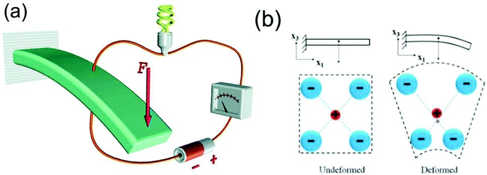 | ||
| Fig. 30 (a) Schematic of a centro-symmetric flexoelectric energy harvester under base excitation. Ref. 158 – reproduced by permission of The Royal Society of Chemistry. (b) Polarisation due to bending of a centro-symmetric beam. Reprinted from ref. 170, with permission from Elsevier. | ||
Han et al. have reported a flexoelectric nanogenerator consisting of direct-grown piezoelectrics on multi-walled carbon nanotubes (mwCNT) in a PDMS matrix.169 Nano-generators based on lead zirconate titanate (PZT)-mwCNTs generated a voltage of 8.6 V and a current of 47 nA from a mechanical load of 20 N; see Table 1. The high performance was reported to originate from the strong connection between the PZT and mwCNTs with an enhanced flexoelectric effect due to the strain gradient in the material. The epitaxial PZT nanogenerators with an internal strain distribution are shown in Fig. 31 where the change in lattice spacing indicates a strain gradient, which are thought to contribute to the enhancement of the nanogenerator properties of the PZT-nwCNT films by combining both flexoelectric and piezoelectric effects. This provides scope for improving the charge generation capability of some of the piezoelectric materials discussed above, in particular nano-sized materials and generators. Rey et al. developed a bio-inspired mechanical energy harvester consisting of a soft flexoelectric membrane148 subjected to fluid-flow-generated mechanical oscillations.153 Deformable flexoelectric membranes were used as the basic unit of transduction, as in Fig. 28, where bending of the membrane leads to an electric polarisation or an electric field leads to bending. This is shown in Fig. 32 where the open circuit (displacement, D = 0) and closed circuit (electric field, E = 0) states are shown and bending is imposed by an externally imposed pressure drop from the contacting fluid phases (P1 and P2) and charge separation in the membrane is due to the flexoelectric effect.
 | ||
| Fig. 31 (a) HRTEM images of epitaxial PZT-CNTs, (b) magnified image of the PZT nanoparticles, and (c) magnified image showing atomic arrangements and strain mismatch (d) atomic arrangement and (e) lattice spacing of PZT and mwCNTs. Adapted from Han et al.169 with permission from Nature Publishing Group (Copyright 2016). | ||
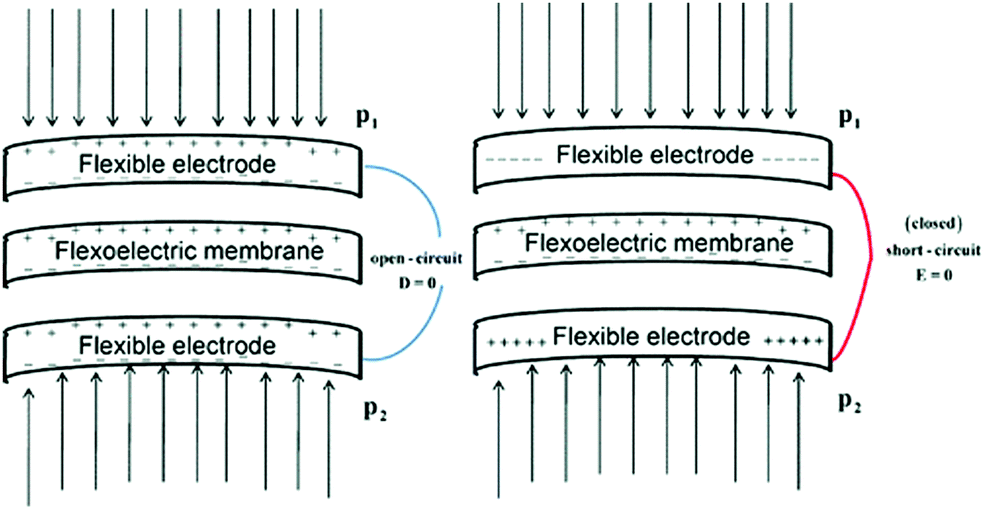 | ||
| Fig. 32 Open (D = 0) and closed circuit (E = 0) states for a flexoelectric membrane under bending. P shows pressure. Reprinted figure with permission from ref. 153. Copyright (2013) by the American Physical Society. | ||
Flexoelectric materials can therefore provide new approaches to create nanodevices for sensing and electromechanical energy harvesting that may be combined with, or even replace, piezoelectric systems. The size effect in this class of materials could provide self-powered integrated nano-systems that make use of mechanical forces in cells to manipulate their biological behaviour. In addition, flexoelectric based energy harvesting techniques offer efficient solutions in electrochemical recovery of ions such as calcium and lithium. For example, Trocoli et al. recently proposed a new method for lithium recovery from brines using an electro-chemical ion-pumping process.171
5.2 Flexo-electric effects in electro-chemical strain microscopy
Electro-chemical strain microscopy (ESM) is a new scanning probe microscopy (SPM) technique that enables local ionic flows and electrochemical reactions in solids to be probed and is based on flexoelectric and bias-strain coupling.172,173Fig. 33 shows an ESM measurement where the film being analysed is composed of mobile charged defects and electrons. The upper SPM tip produces an inhomogeneous electric field that leads to elastic strains that are proportional to the electric field gradient due to flexoelectric coupling. The redistribution of mobile charged particles influences the electric potential distribution in the film and induces local strains that are detected by the SPM tip; thereby providing electro-chemical information about the specimen.174 The models developed that couple the electric–chemical–mechanical–thermal processes in this technique can also take into account bulk defect electrochemical reactions – these new models may provide new insights where ion flow in a mechanical strain or electric field gradient can be used for nano-scale harvesting and storage. | ||
| Fig. 33 Schematic of the electro-chemical processes at the tip–surface junction in electro-chemical strain microscopy. Reprinted from ref. 174 with permission of AIP Publishing. | ||
5.3 Photo-flexo-electric effects
A photo-induced flexoelectric response was initially reported by Spassova for bilayer lipid membranes175 and, recently, flexoelectricity has been reported to be responsible for light-induced current generation at structural boundaries between two phases of ferroelectric bismuth ferrite due to a coupling between strain gradient and photo-electric activity, see Fig. 34.176 A localised light beam creates electron–hole pairs in the material and at grain boundary interfaces the electric fields from a strain gradient due to flexoelectric effect separates the two types of charge, and results in current flow normal to the interface.177 Since the material is also piezoelectric there is potential to combine flexoelectric effects with the piezoelectric and photo-electro-chemical aspects described in Section 3. | ||
| Fig. 34 Strain gradient at the interface of two different structural polymorphs induces a flexoelectric polarisation (dark arrows). Positive (red plus symbols) and negative (blue minus symbols) bound charges are produced which generate a depolarisation electric field (white arrows). This electric field is reflected in the electronic band bending (shown at image bottom). A photon creates an electron at or above the conduction band minimum (CBM) and a hole at or below the valence band maximum (VBM). These light-induced electron–hole pairs are separated before recombination owing because electrons and holes in an electric field move in opposite directions. Reprinted by permission from Macmillan Publishers Ltd: ref. 176, Copyright (2015). | ||
6. Thermoelectric-chemical effects
Thermoelectrics are able to generate electrical energy from spatial thermal gradients, unlike pyroelectric materials that require temperatures that vary with time. Work on using thermoelectric power for water splitting has been reported as early as 1976,178 where a hybrid thermo-chemical water-splitting cycle using solar energy was proposed which consisted of three subsystems. The first subsystem was a photochemical reaction (2Fe2+ + I3− + light → 2Fe3+ + 3I−) that was achieved in a flat cell through which the liquid reactant flowed. The cell was placed in direct sunlight above a Fresnel lens, as in Fig. 35 (upper right). The second subsystem was below the Fresnel lens where the remaining solar energy was concentrated onto a thermoelectric element. Cooling fins were used on the other side of the thermoelectric generator to maintain a temperature gradient. The final subsystem consisted of two electrolysers that combine the products of the photo-chemical reactions and electrolysis (Fig. 35, left). The overall efficiency was estimated as 15–25% with an initial production rate of one liter per hour of hydrogen was achieved;178 further work179 indicated that while the efficiency of the thermoelectric device is as low as 5%, the overall efficiency of hydrogen production can be raised to 20% by the additional electric power from the thermoelectric. Photo-electro-chemical (PEC) conversion of solar energy for water splitting has also used with thermoelectric devices. Self-biased water splitting was achieved by Jung et al. since the PEC system operated spontaneously on application of an overpotential generated by a thermoelectric. The system therefore allowed capture of both photons and waste heat and achieved a hydrogen power of 55 mW cm−2.181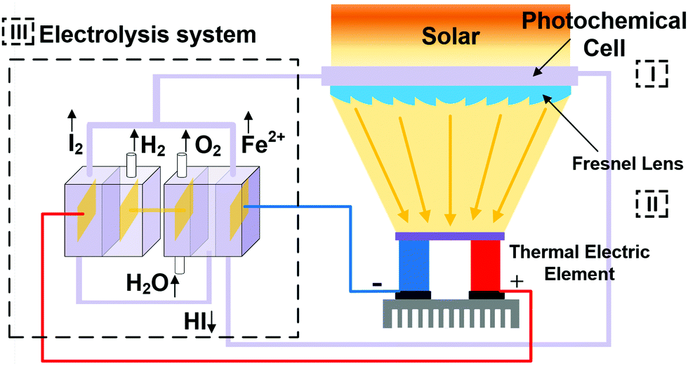 | ||
| Fig. 35 Schematic of hybrid thermo-chemical water splitting, as described by ref. 178. Subsystem I is the photochemical cell. Subsystem II is the Fresnel lens and thermoelectric. Subsystem III is the electrolysis system. | ||
Chen et al.180 reported a microbial electrolysis cell (MEC) to produce H2 from acetate where an additional voltage was supplied by a thermoelectric to overcome the energy barrier, see Fig. 36. They showed that the thermoelectric micro-converter could convert waste heat energy to electricity, even at relatively low temperature differences of 5 °C, and the hydrogen yield was increased from 1.05 to 2.7 mol mol−1 acetate and the coulombic efficiency increased from 27 to 83%. Rectification in not required for thermoelectrics since a unipolar output is achieved, provided the temperature gradient does not change sign. However, some conditioning of the voltage is necessary to ensure the voltage is at an appropriate output level since output voltages are typically low compared to the other harvesting approaches; see Table 1. Liu et al. have recently reported the coupling of both thermo-electricity and electro-catalysis for hydrogen production via a PbTe–PbS/TiO2 heterojunction.182 The triboelectric–thermoelectric–photovoltaic water splitting cell of Yang et al.97 inspired an overview by Andrei et al.183 on the potential for creating hybrid thermoelectric systems and the reader is referred to this excellent opinion article for additional details on thermoelectric devices for water splitting.
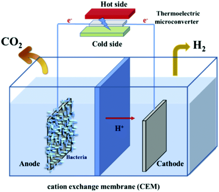 | ||
| Fig. 36 Schematic of the coupled thermo-electric microbial electrolysis cell (MEC) system. Reprinted from ref. 180, Copyright(2016), with permission from Elsevier. | ||
Electro-chemical effects in thermoelectric polymers are also attracting attention. Ion conducting materials have large Seebeck coefficients, and an advantage of polymers over inorganic materials is their high ionic conductivity at ambient temperature. As an example, poly(3,4-ethylene dioxythiophene):poly(styrene sulfonate), namely PEDOT:PSS, has demonstrated a large, but short-term increase, in Seebeck coefficient and Chang et al. has shown that the duration of the ionic Seebeck enhancement can be improved by controlling whether electro-chemistry occurs at the (PEDOT:PSS)/electrode interface.184
7. Photovoltaic-chemical coupling
Solar energy is an important renewable and efficient clean energy source, and significant effort has been made to couple this form of energy to electro-chemical systems. Since Fujishima et al. first reported photo-electro-chemical water splitting185 and photo-reduction of CO2186 on TiO2, in 1972 and 1979, respectively, numerous studies have focused on photo-catalytic materials and mechanisms, which have been summarised in a number of detailed reviews on the topic.187–194 The impact of mechanical loads on the generation, separation, and recombination of photon-induced carriers has also been recently reviewed in the context of piezo-phototronic effects.195As this review has a focus on the coupling of energy harvesting devices to electro-chemical systems, we will overview efforts on the use of photovoltaics as a power source for applications related to water splitting, CO2 reduction and water treatment. Due to the relative maturity of solar cell technologies, power levels can be larger than the μW to mW range that is typical of ‘energy harvesting’ and can be in the W to MW range,196 which is typical of ‘energy generation’. Recent examples of emerging applications are now described.
As already highlighted for the piezo-, pyro- and tribo-electric systems, water splitting is a widely explored application to couple with solar harvesters.185,197–207 In terms of the potential configurations for coupling a photovoltaic to an electro-chemical cell, Bonke et al.197 illustrated three main approaches. This included a wireless, wired and modular photo-electro-chemical (PEC) system, as shown in Fig. 37 to achieve water splitting viaeqn (1) and (2). The developed system employed the simple modular configuration in Fig. 37c, using nickel foam electrodes and a commercial GaInP/GaAs/Ge multi-junction photovoltaic module with a solar-to-electrical power conversion efficiency of 37% under concentrated solar conditions. By optimizing the electrode material, electrode size, electrolyser conditions and using concentrated solar power the solar-energy to fuel-energy conversion efficiency was 22.4%, which was higher than previously reported results that were typically 10–18%. Solar cells have also been coupled to a proton-exchange membrane (PEM) electrolyser to generate hydrogen, with a maximum efficiency of 16.8%.204,205,208
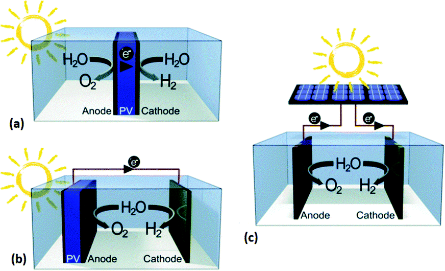 | ||
| Fig. 37 Schematic of light-driven water electrolysis approaches. (a) Fully integrated and wireless photo-electro-chemical (PEC) system; (b) partially integrated and wired PEC; (c) non-integrated and modular PEC. Reproduced from ref. 197 with permission from The Royal Society of Chemistry. | ||
Another promising approach is the electro-chemical reduction of CO2 into fuels.186,209–213 Schreier et al.209 used atomic layer deposition of SnO2 on CuO nanowires to produce a catalyst for CO2 reduction to CO, which was then combined with a triple junction GaInP/GaInAs/Ge photovoltaic cell (PV cell). This is shown in Fig. 38, which also shows a bipolar membrane as the separator to allow for operation using a different catholyte and anolyte. Surface modification of the CuO nanowire electrodes with SnO2 provided improved selectivity of the catalyst, and the solar cell was used to drive the electro-chemical reaction between the anode and cathode. Photolysis of CO2 with a peak solar-to-CO free-energy conversion efficiency of 13.4% was achieved in a system that used far more abundant and lower-cost materials, as compared to other approaches that employed noble metals.
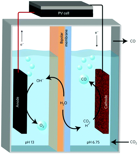 | ||
| Fig. 38 Schematic of solar-driven CO2 reduction device. Anode: reaction: 2OH− → H2O + ½O2 + 2e−; cathode reaction: CO2 + 2H+ + 2e− → CO + H2O. Reprinted by permission from Macmillan Publishers Ltd: ref. 209 (Copyright 2017). | ||
An additional application is the use of photovoltaic cells for water treatment.214–219 Wang et al.219 have recently reported a hybrid photovoltaic-solar water disinfection system with a dual-axis tracking system to provide drinkable water and renewable electricity. Fig. 39 shows a schematic of the hybrid system, where the use of a V-trough concentrator was found to significantly improve the sterilisation efficiency compared to a non-concentrating system; the addition of H2O2 to the water also aided disinfection. Two types of bacteria, Salmonella and Escherichia coli, were evaluated and it was demonstrated that they were completely inactivated in 2.5 h and 1.25 h respectively. As with piezo- and tribo-electric systems, photovoltaics have also be used for corrosion protection, such as electro-chemical chloride extraction in concrete;220 electro-chemical refrigeration221 has also been explored.
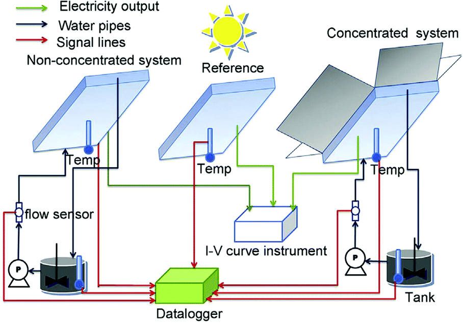 | ||
| Fig. 39 Schematic of hybrid photovoltaic solar water disinfection system. Reprinted from ref. 219. Copyright (2016), with permission from Elsevier. | ||
8. Conclusions and perspectives
This review has covered in detail the progress to date on energy harvesting based on piezoelectric, pyroelectric triboelectric, flexoelectric, thermoelectric and photovoltaic effects that are coupled to electro-chemical systems. Table 1 provides a summary of the harvesting approaches and potential applications which cover a wide range of electro-chemical processes including water splitting, water treatment such as disinfection and degradation of pollutants, corrosion protection, materials synthesis including electro-deposition and oxidation, sensing and electro-chromic systems. The energy sources are varied and include thermal, solar/light, wave/water flow, wind, vibrations and mechanical loads; hybrid systems are also being developed to overcome the intermittent nature of some ambient sources of energy. Since a number of harvesting mechanisms generate AC electrical outputs in response to compressive/tensile loads or heating/cooling cycles some form of rectification is often required to maintain a unipolar operation when the harvester is coupled to cathodes and anodes. Voltage transformation, typically to reduce the high voltages generated by tribo- & piezo-electric (see Table 1), is also required; although if the generated potential is too low to drive a specific electro-chemical reaction there is scope to increase the operating voltage. While the voltages are high (typically 0.02 V to 1.3 kV) to drive the electro-chemical reaction, currents are often low (14.5 μA to 13 mA) which limits the charge and extent of the electro-chemical reaction (eqn (3)); although there is growing interest in potential for scale up.222 To date, rectification methods applied to electro-chemical systems have been relatively simple, such as simple diode and full wave rectification, while in conventional harvesting applications a range power management circuits have been developed to minimise losses and optimise impedance matching of the harvester to the electrical load; this provides scope for further improvement in the electro-chemical applications.223 Greater information regarding overall efficiencies of systems would also be of interest. For solar harvesting, the system efficiencies are more widely reported, and the other harvesting approaches would benefit from similar information. Solar is also typically associated with larger harvesting systems. Tribo-electric devices have been typically used as an external charge source to drive an electro-chemical reaction since a complete TENG device is typically required to achieve charge generation. However, for pyro- and piezo-electric systems the inherent spontaneous polarisation of the material enables them to be either used as an external thermal or vibration harvesting device or as fine particulates or porous material dispersed in an electrolyte. This is of interest since it enables the high surface areas (and therefore surface charge) associated with nano-sized particulates and architectures. This provides an opportunity to overcome the low electric current/charge limitations in Table 1. The potential to exploit the high surface area of 2D materials, and their ability to also exhibit flexoelectric effects, is also of interest. A closer integration of TENGs with electrolytes may provide new directions for research and triboelectric effects associated with electrical double layers has recently been reported in novel sensing tribo-devices.224There is also potential to combine the active harvesting material with storage, as an example the understanding of the pyro- and piezo-electric properties of metal–organic frameworks (MOFs) is growing,225 and these materials also have potential for gas storage applications so that combined harvesting for hydrogen production and storage may be feasible. The potential of pyroelectric effects to achieve water splitting by thermal cycling above and below the Curie temperature is a new and exciting prospect for hydrogen generation, but experimental data is needed to validation model predictions and mechanisms.
Flexo-electric systems are clearly at an early stage, but their scope for nano-scale systems and ability to exploit membrane effects provides intriguing potential for membrane based nano-generators combined with ion pumping for charge storage applications. There is also scope for using strain gradients and flexoelectric effects at interfaces to influence and enhance photo-flexo-electro-chemical effects and subjecting the materials to mechanical loads or thermal expansion. Ferro-electrets or electro-active polymers could also be explored, and there has been limited work on electro-magnetic harvesting. Hybrid systems that use the DC output of thermoelectric modules are attractive due to their ability to supply overpotentials to electro-chemical reactions and new thermoelectric polymers and nanocomposites also provide new directions.226,227 There are also additional electro-chemical harvesting mechanisms to couple with the harvesting approaches described here. For example, there are sensitised thermal cells, thermo-galvanic and thermo-electro-chemical cells (thermocells),228–235 where the dependence of electrode potential on temperature is used to construct harvesting thermal cycles and this has recently been reviewed.236 Piezo-galvanic effects have even been observed where applying an asymmetric force to an electrolyte cell produces an electrical response237 and thermo-magnetic effects for water splitting.238
Finally a number of new electro-chemical processes could be explored in attempt to exploit the high voltages of the energy harvesting mechanism described in this review; such as material synthesis based on electro-chemical exfoliation.239 The potential of local energy harvesting to supply bioreactors to produce protein as a food source has recently been described.240 Finally, while there is a growing number of academic publications, and patents, there is also a need to transfer such ideas and potential applications into commercial activities to fully exploit the potential of the applications described here.
Conflicts of interest
There are no conflicts to declare.Acknowledgements
Dr Y. Zhang would like to acknowledge the European Commission's Marie Skłodowska-Curie Actions (MSCA), through the Marie Skłodowska-Curie Individual Fellowships (IF-EF) (H2020-MSCA-IF-2015-EF-703950-HEAPPs) under Horizon 2020. Prof. C. R. Bowen, Dr M. Xie and Dr V. Adamaki would like to acknowledge the funding from the European Research Council under the European Union's Seventh Framework Programme (FP/2007–2013)/ERC Grant Agreement No. 320963 on Novel Energy Materials, Engineering Science and Integrated Systems (NEMESIS).Notes and references
- A. Vlad, N. Singh, C. Galande and P. M. Ajayan, Adv. Energy Mater., 2015, 5, 1402115 CrossRef.
- H. Wei, D. Cui, J. Ma, L. Chu, X. Zhao, H. Song, H. Liu, T. Liu, N. Wang and Z. Guo, J. Mater. Chem. A, 2017, 5, 1873–1894 CAS.
- Y. Zhong, X. H. Xia, W. J. Mai, J. P. Tu and H. J. Fan, Adv. Mater. Technol., 2017, 1700182 CrossRef.
- J.-H. Lee, J. Kim, T. Y. Kim, M. S. Al Hossain, S.-W. Kim and J. H. Kim, J. Mater. Chem. A, 2016, 4, 7983–7999 CAS.
- C. R. Bowen, J. Taylor, E. LeBoulbar, D. Zabek, A. Chauhan and R. Vaish, Energy Environ. Sci., 2014, 7, 3836–3856 Search PubMed.
- C. R. Bowen, H. A. Kim, P. M. Weaver and S. Dunn, Energy Environ. Sci., 2014, 7, 25–44 CAS.
- Z. L. Wang, Mater. Today, 2017, 20, 74–82 CrossRef.
- Z. L. Wang, Faraday Discuss., 2014, 176, 447–458 RSC.
- G. Tan, L.-D. Zhao and M. G. Kanatzidis, Chem. Rev., 2016, 116, 12123–12149 CrossRef CAS PubMed.
- P. Zubko, G. Catalan and A. K. Tagantsev, Annu. Rev. Mater. Res., 2013, 43, 387–421 CrossRef CAS.
- F. Invernizzi, S. Dulio, M. Patrini, G. Guizzetti and P. Mustarelli, Chem. Soc. Rev., 2016, 45, 5455–5473 RSC.
- R. E. Blankenship, D. M. Tiede, J. Barber, G. W. Brudvig, G. Fleming, M. Ghirardi, M. R. Gunner, W. Junge, D. M. Kramer, A. Melis, T. A. Moore, C. C. Moser, D. G. Nocera, A. J. Nozik, D. R. Ort, W. W. Parson, R. C. Prince and R. T. Sayre, Science, 2011, 332, 805–809 CrossRef CAS PubMed.
- A. Shiroudi, M. S. Deleuze and S. A. Mousavifar, Int. J. Ambient Energy, 2017, 38, 240–249 CrossRef CAS.
- A. Mostafaeipour, M. Khayyami, A. Sedaghat, K. Mohammadi, S. Shamshirband, M.-A. Sehati and E. Gorakifard, Int. J. Hydrogen Energy, 2016, 41, 6200–6210 CrossRef CAS.
- M. Qolipour, A. Mostafaeipour and O. M. Tousi, Renewable Sustainable Energy Rev., 2017, 78, 113–123 CrossRef.
- R. M. Navarro, M. A. Peña and J. L. G. Fierro, Chem. Rev., 2007, 107, 3952–3991 CrossRef CAS PubMed.
- A. Kudo and Y. Miseki, Chem. Soc. Rev., 2009, 38, 253–278 RSC.
- Y. Zheng, Y. Jiao, M. Jaroniec and S. Z. Qiao, Angew. Chem., Int. Ed., 2015, 54, 52–65 CrossRef CAS PubMed.
- V. Artero, M. Chavarot-Kerlidou and M. Fontecave, Angew. Chem., Int. Ed., 2011, 50, 7238–7266 CrossRef CAS PubMed.
- M. Xie, S. Dunn, E. L. Boulbar and C. R. Bowen, Int. J. Hydrogen Energy, 2017, 42, 23437–23445 CrossRef CAS.
- M. Baldauf, T. Hammer, S. Kosse and G. Zimmermann, Germany Pat., WO 2012110352 A1, 2012 Search PubMed.
- C. Cherkouk, M. Zschornak, J. Hanzig, M. Nentwich, F. Meutzner, M. Urena, T. Leisegang and D. C. Meyer, COMSOL multiphysics® simulation of energy conversion and storage concepts based on oxide crystals, 2014 Search PubMed.
- R. Belitz, P. Meisner, M. Coeler, U. Wunderwald, J. Friedrich, J. Zosel, M. Schelter, S. Jachalke and E. Mehner, Energy Harv. Syst., 2017 DOI:10.1515/ehs-2016-0009.
- S. Habicht, R. J. Nemanich and A. Gruverman, Nanotechnology, 2008, 19, 495303 CrossRef CAS PubMed.
- A. Kakekhani, S. Ismail-Beigi and E. I. Altman, Surf. Sci., 2016, 650, 302–316 CrossRef CAS.
- A. Kakekhani and S. Ismail-Beigi, ACS Catal., 2015, 5, 4537–4545 CrossRef CAS.
- A. Kakekhani and S. Ismail-Beigi, Phys. Chem. Chem. Phys., 2016, 18, 19676–19695 RSC.
- A. Kakekhani and S. Ismail-Beigi, J. Mater. Chem. A, 2016, 4, 5235–5246 CAS.
- X.-W. Liu, W.-W. Li and H.-Q. Yu, Chem. Soc. Rev., 2014, 43, 7718–7745 RSC.
- T. F. Wiesner, Pyroelectrically-mediated reduction–oxidation reactions, Texas Tech University, 2010 Search PubMed.
- E. Gutmann, A. Benke, K. Gerth, H. Böttcher, E. Mehner, C. Klein, U. Krause-Buchholz, U. Bergmann, W. Pompe and D. C. Meyer, J. Phys. Chem. C, 2012, 116, 5383–5393 CAS.
- A. Benke, E. Mehner, M. Rosenkranz, E. Dmitrieva, T. Leisegang, H. Stöcker, W. Pompe and D. C. Meyer, J. Phys. Chem. C, 2015, 119, 18278–18286 CAS.
- J. Wu, W. Mao, Z. Wu, X. Xu, H. You, A. X. Xue and Y. Jia, Nanoscale, 2016, 8, 7343–7350 RSC.
- Y. Xia, Y. Jia, W. Qian, X. Xu, Z. Wu, Z. Han, Y. Hong, H. You, M. Ismail, G. Bai and L. Wang, Metals, 2017, 7, 122 CrossRef.
- W. Qian, Z. Wu, Y. Jia, Y. Hong, X. Xu, H. You, Y. Zheng and Y. Xia, Electrochem. Commun., 2017, 81, 124–127 CrossRef CAS.
- C. Forman, M. Gootz, D. Scheithauer, M. Herrmann, E. Mehner, B. Meyer, D. C. Meyer, I. Muritala, R. Pardemann and O. Schulze, European Pat., EP 3027551 A2, 2016 Search PubMed.
- Y. Yang, H. Zhang, S. Lee, D. Kim, W. Hwang and Z. L. Wang, Nano Lett., 2013, 13, 803–808 CrossRef CAS PubMed.
- H. Zhang, S. Zhang, G. Yao, Z. Huang, Y. Xie, Y. Su, W. Yang, C. Zheng and Y. Lin, ACS Appl. Mater. Interfaces, 2015, 7, 28142–28147 CAS.
- T. Zhao, W. Jiang, D. Niu, H. Liu, B. Chen, Y. Shi, L. Yin and B. Lu, Appl. Energy, 2017, 195, 754–760 CrossRef CAS.
- R. W. Salt, Science, 1961, 133, 458–459 CAS.
- D. Ehre, E. Lavert, M. Lahav and I. Lubomirsky, Science, 2010, 327, 672 CrossRef CAS PubMed.
- D. Spitzner, U. Bergmann, S. Apelt, R. Boucher and H.-P. Wiesmann, Coatings, 2015, 5, 724 CrossRef CAS.
- S. Piperno, E. Mirzadeh, E. Mishuk, D. Ehre, S. Cohen, M. Eisenstein, M. Lahav and I. Lubomirsky, Angew. Chem., Int. Ed., 2013, 52, 6513–6516 CrossRef CAS PubMed.
- A. Pichon, Nat. Chem., 2013, 5, 551 CrossRef.
- D. Ehre, B. Alik, E. Mishuk, M. Lahav and I. Lubomirsky, Proceedings of the 2014 ESA Annual Meeting on Electrostatics, 2014 Search PubMed.
- S. Coppola, Manipulation of Multiphase Materials for Touch-less Nanobiotechnology: A Pyrofluidic Platform, Springer International Publishing, Cham, 2016, pp. 5–22 DOI:10.1007/978-3-319-31059-6_2.
- X. Xi, D. Zhao, F. Tong and T. Cao, Soft Matter, 2012, 8, 298–302 RSC.
- S. Grilli, L. Miccio, V. Vespini, A. Finizio, S. De Nicola and P. Ferraro, Opt. Express, 2008, 16, 8084–8093 CAS.
- K.-S. Hong, H. Xu, H. Konishi and X. Li, J. Phys. Chem. Lett., 2010, 1, 997–1002 CrossRef CAS.
- M. B. Starr and X. Wang, Nano Energy, 2015, 14, 296–311 CrossRef CAS.
- M. B. Starr and X. Wang, Sci. Rep., 2013, 3, 2160 CrossRef PubMed.
- M. B. Starr, J. Shi and X. Wang, Angew. Chem., Int. Ed., 2012, 51, 5962–5966 CrossRef CAS PubMed.
- M. E. Lines and A. M. Glass, Principles and Applications of Ferroelectrics and Related Materials, Oxford Scholarship Online, 2001 Search PubMed.
- J. Zhang, Z. Wu, Y. Jia, J. Kan and G. Cheng, Sensors, 2013, 13, 367 CrossRef CAS PubMed.
- C. F. Tan, W. L. Ong and G. W. Ho, ACS Nano, 2015, 9, 7661–7670 CrossRef CAS PubMed.
- W. Yang, Y. Yu, M. B. Starr, X. Yin, Z. Li, A. Kvit, S. Wang, P. Zhao and X. Wang, Nano Lett., 2015, 15, 7574–7580 CrossRef CAS PubMed.
- K.-S. Hong, H. Xu, H. Konishi and X. Li, J. Phys. Chem. C, 2012, 116, 13045–13051 CAS.
- H. Lin, Z. Wu, Y. Jia, W. Li, R.-K. Zheng and H. Luo, Appl. Phys. Lett., 2014, 104, 162907 CrossRef.
- W. Lv, L. Kong, S. Lan, J. Feng, Y. Xiong and S. Tian, J. Chem. Technol. Biotechnol., 2017, 92, 152–156 CrossRef CAS.
- Z. L. Wang, Nano Today, 2010, 5, 540–552 CrossRef CAS.
- X. Xue, W. Zang, P. Deng, Q. Wang, L. Xing, Y. Zhang and Z. L. Wang, Nano Energy, 2015, 13, 414–422 CrossRef CAS.
- M.-K. Lo, S.-Y. Lee and K.-S. Chang, J. Phys. Chem. C, 2015, 119, 5218–5224 CAS.
- Y.-T. Wang and K.-S. Chang, J. Am. Ceram. Soc., 2016, 99, 2593–2600 CrossRef CAS.
- D. Hong, W. Zang, X. Guo, Y. Fu, H. He, J. Sun, L. Xing, B. Liu and X. Xue, ACS Appl. Mater. Interfaces, 2016, 8, 21302–21314 CAS.
- C. Sun, Y. Fu, Q. Wang, L. Xing, B. Liu and X. Xue, RSC Adv., 2016, 6, 87446–87453 RSC.
- H. Li, Y. Sang, S. Chang, X. Huang, Y. Zhang, R. Yang, H. Jiang, H. Liu and Z. L. Wang, Nano Lett., 2015, 15, 2372–2379 CrossRef CAS PubMed.
- M. A. Khan, M. A. Nadeem and H. Idriss, Surf. Sci. Rep., 2016, 71, 1–31 CrossRef CAS.
- Y. Cui, J. Briscoe and S. Dunn, Chem. Mater., 2013, 25, 4215–4223 CrossRef CAS.
- Y. Cui, S. M. Goldup and S. Dunn, RSC Adv., 2015, 5, 30372–30379 RSC.
- P. M. Jones and S. Dunn, J. Phys. D: Appl. Phys., 2009, 42, 065408 CrossRef.
- P. M. Jones and S. Dunn, Nanotechnology, 2007, 18, 185702 CrossRef.
- M. Stock and S. Dunn, IEEE Trans. Ultrason. Ferroelectr. Freq. Control, 2011, 58, 1988–1993 CrossRef PubMed.
- M. Stock and S. Dunn, J. Phys. Chem. C, 2012, 116, 20854–20859 CAS.
- D. Tiwari and S. Dunn, Mater. Lett., 2012, 79, 18–20 CrossRef CAS.
- X. Xue, S. Wang, W. Guo, Y. Zhang and Z. L. Wang, Nano Lett., 2012, 12, 5048–5054 CrossRef CAS PubMed.
- X. Xue, P. Deng, S. Yuan, Y. Nie, B. He, L. Xing and Y. Zhang, Energy Environ. Sci., 2013, 6, 2615–2620 CAS.
- Y.-S. Kim, Y. Xie, X. Wen, S. Wang, S. J. Kim, H.-K. Song and Z. L. Wang, Nano Energy, 2015, 14, 77–86 CrossRef CAS.
- L. Xing, Y. Nie, X. Xue and Y. Zhang, Nano Energy, 2014, 10, 44–52 CrossRef CAS.
- Z. Yan, Z. Yujing, X. Xinyu, C. Chunxiao, H. Bin, N. Yuxin, D. Ping and W. Zhong Lin, Nanotechnology, 2014, 25, 105401 CrossRef PubMed.
- A. Ramadoss, B. Saravanakumar, S. W. Lee, Y.-S. Kim, S. J. Kim and Z. L. Wang, ACS Nano, 2015, 9, 4337–4345 CrossRef CAS PubMed.
- R. Song, H. Jin, X. Li, L. Fei, Y. Zhao, H. Huang, H. L.-W. Chan, Y. Wang and Y. Chai, J. Mater. Chem. A, 2015, 3, 14963–14970 CAS.
- F. Wang, C. Jiang, C. Tang, S. Bi, Q. Wang, D. Du and J. Song, Nano Energy, 2016, 21, 209–216 CrossRef CAS.
- K. Parida, V. Bhavanasi, V. Kumar, J. Wang and P. S. Lee, J. Power Sources, 2017, 342, 70–78 CrossRef CAS.
- B.-S. Lee, J. Yoon, C. Jung, D. Y. Kim, S.-Y. Jeon, K.-H. Kim, J.-H. Park, H. Park, K. H. Lee, Y.-S. Kang, J.-H. Park, H. Jung, W.-R. Yu and S.-G. Doo, ACS Nano, 2016, 10, 2617–2627 CrossRef CAS PubMed.
- S. Kim, S. J. Choi, K. Zhao, H. Yang, G. Gobbi, S. Zhang and J. Li, Nat. Commun., 2016, 7, 10146 CrossRef CAS PubMed.
- K. Noris-Suárez, J. Lira-Olivares, A. M. Ferreira, A. Graterol, J. L. Feijoo and W. S. Lee, Mater. Sci. Forum, 2007, 544–545, 981–984 CrossRef.
- S. B. Lang, S. A. M. Tofail, A. L. Kholkin, M. Wojtaś, M. Gregor, A. A. Gandhi, Y. Wang, S. Bauer, M. Krause and A. Plecenik, Sci. Rep., 2013, 3, 2215 CrossRef CAS PubMed.
- F. R. Baxter, C. R. Bowen, I. G. Turner and A. C. E. Dent, Ann. Biomed. Eng., 2010, 38, 2079–2092 CrossRef CAS PubMed.
- P. Soroushian, R.-U.-D. Nassar and A. M. Balachandra, J. Intell. Mater. Syst., 2013, 24, 441–453 CrossRef.
- N. Touach, V. M. Ortiz-Martínez, M. J. Salar-García, A. Benzaouak, F. Hernández-Fernández, A. P. de Ríos, M. El Mahi and E. M. Lotfi, Particuology, 2017, 34, 147–155 CrossRef CAS.
- F.-R. Fan, Z.-Q. Tian and Z. Lin Wang, Nano Energy, 2012, 1, 328–334 CrossRef CAS.
- G. Zhu, Y. S. Zhou, P. Bai, X. S. Meng, Q. Jing, J. Chen and Z. L. Wang, Adv. Mater., 2014, 26, 3788–3796 CrossRef CAS PubMed.
- W. Tang, T. Jiang, F. R. Fan, A. F. Yu, C. Zhang, X. Cao and Z. L. Wang, Adv. Funct. Mater., 2015, 25, 3718–3725 CrossRef CAS.
- Z. L. Wang, T. Jiang and L. Xu, Nano Energy, 2017, 39, 9–23 CrossRef CAS.
- X. Cao, Y. Jie, N. Wang and Z. L. Wang, Adv. Energy Mater., 2016, 6, 1600665 CrossRef.
- W. Tang, Y. Han, C. B. Han, C. Z. Gao, X. Cao and Z. L. Wang, Adv. Mater., 2015, 27, 272–276 CrossRef CAS PubMed.
- Y. Yang, H. Zhang, Z.-H. Lin, Y. Liu, J. Chen, Z. Lin, Y. S. Zhou, C. P. Wong and Z. L. Wang, Energy Environ. Sci., 2013, 6, 2429–2434 CAS.
- S. A. Nahian, R. K. Cheedarala and K. K. Ahn, Nano Energy, 2017, 38, 447–456 CrossRef CAS.
- X. Yu, X. Han, Z. Zhao, J. Zhang, W. Guo, C. Pan, A. Li, H. Liu and Z. Lin Wang, Nano Energy, 2015, 11, 19–27 CrossRef CAS.
- W. Zhou, Z. Yin, Y. Du, X. Huang, Z. Zeng, Z. Fan, H. Liu, J. Wang and H. Zhang, Small, 2013, 9, 140–147 CrossRef CAS PubMed.
- T. Li, Y. Xu, F. Xing, X. Cao, J. Bian, N. Wang and Z. L. Wang, Adv. Energy Mater., 2017, 7, 1700124 CrossRef.
- Y.-C. Pu, G. Wang, K.-D. Chang, Y. Ling, Y.-K. Lin, B. C. Fitzmorris, C.-M. Liu, X. Lu, Y. Tong, J. Z. Zhang, Y.-J. Hsu and Y. Li, Nano Lett., 2013, 13, 3817–3823 CrossRef CAS PubMed.
- P. Song, S. Kuang, N. Panwar, G. Yang, D. J. H. Tng, S. C. Tjin, W. J. Ng, M. B. A. Majid, G. Zhu, K.-T. Yong and Z. L. Wang, Adv. Mater., 2017, 29, 1605668 CrossRef PubMed.
- S. Yuanjie, Y. Ya, Z. Hulin, X. Yannan, W. Zhiming, J. Yadong, F. Naoki, B. Yoshio and W. Zhong Lin, Nanotechnology, 2013, 24, 295401 CrossRef PubMed.
- Y. Yang, H. Zhang, Y. Liu, Z.-H. Lin, S. Lee, Z. Lin, C. P. Wong and Z. L. Wang, ACS Nano, 2013, 7, 2808–2813 CrossRef CAS PubMed.
- Q. Jiang, Y. Han, W. Tang, H. Zhu, C. Gao, S. Chen, M. Willander, X. Cao and Z. Lin Wang, Nano Energy, 2015, 15, 266–274 CrossRef CAS.
- Z. Li, J. Chen, J. Yang, Y. Su, X. Fan, Y. Wu, C. Yu and Z. L. Wang, Energy Environ. Sci., 2015, 8, 887–896 CAS.
- Q. Jiang, Y. Jie, Y. Han, C. Gao, H. Zhu, M. Willander, X. Zhang and X. Cao, Nano Energy, 2015, 18, 81–88 CrossRef CAS.
- S. Chen, C. Gao, W. Tang, H. Zhu, Y. Han, Q. Jiang, T. Li, X. Cao and Z. Wang, Nano Energy, 2015, 14, 217–225 CrossRef CAS.
- X. Zheng, J. Su, X. Wei, T. Jiang, S. Gao and Z. L. Wang, Adv. Mater., 2016, 28, 5188–5194 CrossRef CAS PubMed.
- S. Gao, J. Su, M. Wang, X. Wei, X. Zheng and T. Jiang, Nano Energy, 2016, 30, 52–58 CrossRef CAS.
- S. Gao, J. Su, X. Wei, M. Wang, M. Tian, T. Jiang and Z. L. Wang, ACS Nano, 2017, 11, 770–778 CrossRef CAS PubMed.
- S. Gao, Y. Chen, J. Su, M. Wang, X. Wei, T. Jiang and Z. L. Wang, ACS Nano, 2017, 11, 3965–3972 CrossRef CAS PubMed.
- G. Chen, Sep. Purif. Technol., 2004, 38, 11–41 CrossRef CAS.
- S. Chen, N. Wang, L. Ma, T. Li, M. Willander, Y. Jie, X. Cao and Z. L. Wang, Adv. Energy Mater., 2016, 6, 1501778 CrossRef.
- M.-H. Yeh, H. Guo, L. Lin, Z. Wen, Z. Li, C. Hu and Z. L. Wang, Adv. Funct. Mater., 2016, 26, 1054–1062 CrossRef CAS.
- S.-B. Jeon, S. Kim, S.-J. Park, M.-L. Seol, D. Kim, Y. K. Chang and Y.-K. Choi, Nano Energy, 2016, 28, 288–295 CrossRef CAS.
- Z. Li, J. Chen, J. Zhou, L. Zheng, K. C. Pradel, X. Fan, H. Guo, Z. Wen, M.-H. Yeh, C. Yu and Z. L. Wang, Nano Energy, 2016, 22, 548–557 CrossRef CAS.
- X. J. Zhao, G. Zhu, Y. J. Fan, H. Y. Li and Z. L. Wang, ACS Nano, 2015, 9, 7671–7677 CrossRef CAS PubMed.
- W. Guo, X. Li, M. Chen, L. Xu, L. Dong, X. Cao, W. Tang, J. Zhu, C. Lin, C. Pan and Z. L. Wang, Adv. Funct. Mater., 2014, 24, 6691–6699 CrossRef CAS.
- X. Li, J. Tao, W. Guo, X. Zhang, J. Luo, M. Chen, J. Zhu and C. Pan, J. Mater. Chem. A, 2015, 3, 22663–22668 CAS.
- Z. Wang, L. Cheng, Y. Zheng, Y. Qin and Z. L. Wang, Nano Energy, 2014, 10, 37–43 CrossRef CAS.
- H. R. Zhu, W. Tang, C. Z. Gao, Y. Han, T. Li, X. Cao and Z. L. Wang, Nano Energy, 2015, 14, 193–200 CrossRef CAS.
- Y. Feng, Y. Zheng, Z. U. Rahman, D. Wang, F. Zhou and W. Liu, J. Mater. Chem. A, 2016, 4, 18022–18030 CAS.
- S. Cui, Y. Zheng, J. Liang and D. Wang, Chem. Sci., 2016, 7, 6477–6483 RSC.
- G. Zhu, C. Pan, W. Guo, C.-Y. Chen, Y. Zhou, R. Yu and Z. L. Wang, Nano Lett., 2012, 12, 4960–4965 CrossRef CAS PubMed.
- J. Wang, Z. Wen, Y. Zi, P. Zhou, J. Lin, H. Guo, Y. Xu and Z. L. Wang, Adv. Funct. Mater., 2016, 26, 1070–1076 CrossRef CAS.
- J. Wang, Z. Wen, Y. Zi, L. Lin, C. Wu, H. Guo, Y. Xi, Y. Xu and Z. L. Wang, Adv. Funct. Mater., 2016, 26, 3542–3548 CrossRef CAS.
- H. Zhu, Y. Xu, Y. Han, S. Chen, T. Zhou, M. Willander, X. Cao and Z. Wang, Nano Res., 2015, 8, 3604–3611 CrossRef CAS.
- Y. Jie, N. Wang, X. Cao, Y. Xu, T. Li, X. Zhang and Z. L. Wang, ACS Nano, 2015, 9, 8376–8383 CrossRef CAS PubMed.
- Z. Li, J. Chen, H. Guo, X. Fan, Z. Wen, M. H. Yeh, C. Yu, X. Cao and Z. L. Wang, Adv. Mater., 2016, 28, 2983–2991 CrossRef CAS PubMed.
- Z. H. Lin, G. Zhu, Y. S. Zhou, Y. Yang, P. Bai, J. Chen and Z. L. Wang, Angew. Chem., Int. Ed., 2013, 52, 5065–5069 CrossRef CAS PubMed.
- Z. Wen, J. Chen, M.-H. Yeh, H. Guo, Z. Li, X. Fan, T. Zhang, L. Zhu and Z. L. Wang, Nano Energy, 2015, 16, 38–46 CrossRef CAS.
- H. Zhang, Y. Yang, T.-C. Hou, Y. Su, C. Hu and Z. L. Wang, Nano Energy, 2013, 2, 1019–1024 CrossRef CAS.
- H. Zhang, Y. Yang, Y. Su, J. Chen, C. Hu, Z. Wu, Y. Liu, C. Ping Wong, Y. Bando and Z. L. Wang, Nano Energy, 2013, 2, 693–701 CrossRef CAS.
- X. Yang, G. Zhu, S. Wang, R. Zhang, L. Lin, W. Wu and Z. L. Wang, Energy Environ. Sci., 2012, 5, 9462–9466 CAS.
- Y. Song, X. Cheng, H. Chen, J. Huang, X. Chen, M. Han, Z. Su, B. Meng, Z. Song and H. Zhang, J. Mater. Chem. A, 2016, 4, 14298–14306 CAS.
- J.-G. Sun, T. N. Yang, I. S. Kuo, J.-M. Wu, C.-Y. Wang and L.-J. Chen, Nano Energy, 2017, 32, 180–186 CrossRef CAS.
- M.-H. Yeh, L. Lin, P.-K. Yang and Z. L. Wang, ACS Nano, 2015, 9, 4757–4765 CrossRef CAS PubMed.
- F. Zhang, B. Li, J. Zheng and C. Xu, Nanoscale Res. Lett., 2015, 10, 298 CrossRef PubMed.
- M. Zhang, Y. Jie, X. Cao, J. Bian, T. Li, N. Wang and Z. L. Wang, Nano Energy, 2016, 30, 155–161 CrossRef CAS.
- Y.-K. Fuh, S.-C. Li and C.-Y. Chen, APL Mater., 2017, 5, 074202 CrossRef.
- Y. Su, G. Xie, S. Wang, H. Tai, Q. Zhang, H. Du, H. Zhang, X. Du and Y. Jiang, Sens. Actuators, B, 2017, 251, 144–152 CrossRef CAS.
- H. Zhu, N. Wang, Y. Xu, S. Chen, M. Willander, X. Cao and Z. L. Wang, Adv. Funct. Mater., 2016, 26, 3029–3035 CrossRef CAS.
- Y. Zheng, L. Cheng, M. Yuan, Z. Wang, L. Zhang, Y. Qin and T. Jing, Nanoscale, 2014, 6, 7842–7846 RSC.
- L. Su, H. Y. Li, Y. Wang, S. Y. Kuang, Z. L. Wang and G. Zhu, Nano Energy, 2017, 31, 264–269 CrossRef CAS.
- J.-G. Sun, T. N. Yang, I.-S. Kuo, J.-M. Wu, C.-Y. Wang and L.-J. Chen, Nano Energy, 2017, 32, 180–186 CrossRef CAS.
- A. G. Petrov, Biochim. Biophys. Acta, 2002, 1561, 1–25 CrossRef CAS.
- A. Todorov, A. Petrov and J. Fendler, J. Phys. Chem., 1994, 98, 3076–3079 CrossRef CAS.
- Z. Ping-Cheng, A. M. Keleshian and F. Sachs, Nature, 2001, 413, 428 CrossRef PubMed.
- J. Mosbacher, M. Langer, J. Hörber and F. Sachs, J. Gen. Physiol., 1998, 111, 65–74 CrossRef CAS PubMed.
- A. G. Petrov, in Physical and Chemical Bases of Biological Information Transfer, ed. J. G. Vassileva-Popova, Plenum Press, New York, 1975, vol. 111 Search PubMed.
- A. D. Rey, P. Servio and E. Herrera-Valencia, Phys. Rev. E: Stat., Nonlinear, Soft Matter Phys., 2013, 87, 022505 CrossRef PubMed.
- F. Ahmadpoor, Q. Deng, L. Liu and P. Sharma, Phys. Rev. E: Stat., Nonlinear, Soft Matter Phys., 2013, 88, 050701 CrossRef CAS PubMed.
- A. G. Petrov, B. A. Miller, K. Hristova and P. N. Usherwood, Eur. Biophys. J., 1993, 22, 289–300 CAS.
- A. G. Petrov, Anal. Chim. Acta, 2006, 568, 70–83 CrossRef CAS PubMed.
- A. G. Petrov and P. N. Usherwood, Eur. Biophys. J., 1994, 23, 1–19 CrossRef CAS PubMed.
- F. Ahmadpoor and P. Sharma, Nanoscale, 2015, 7, 16555–16570 RSC.
- A. Petrov and L. Mircevova, Gen. Physiol. Biophys., 1986, 5, 391–403 CAS.
- W. E. Brownell, F. Qian and B. Anvari, Biophys. J., 2010, 99, 845–852 CrossRef CAS PubMed.
- W. Brownell, B. Farrell and R. Raphael, BIOPHYSICS OF THE COCHLEA From Molecules to Models, Proceedings of the International Symposium, Titisee, Germany, 2002 Search PubMed.
- W. Brownell, A. Spector, R. Raphael and A. Popel, Annu. Rev. Biomed. Eng., 2001, 3, 169–194 CrossRef CAS PubMed.
- K. D. Breneman, W. E. Brownell and R. D. Rabbitt, PLoS One, 2009, 4, e5201 Search PubMed.
- M. Majdoub, P. Sharma and T. Cagin, Phys. Rev. B: Condens. Matter Mater. Phys., 2008, 77, 125424 CrossRef.
- Y. Qi, J. Kim, T. D. Nguyen, B. Lisko, P. K. Purohit and M. C. McAlpine, Nano Lett., 2011, 11, 1331–1336 CrossRef CAS PubMed.
- M. Majdoub, P. Sharma and T. Çağin, Phys. Rev. B: Condens. Matter Mater. Phys., 2008, 78, 121407 CrossRef.
- K. Wang and B. Wang, Int. J. Eng. Sci., 2017, 116, 88–103 CrossRef.
- K. Wang and B. Wang, Compos. Struct., 2016, 153, 253–261 CrossRef.
- J. K. Han, S. Y. C. Do Hyun Jeon, S. W. Kang, S. A. Yang, S. D. Bu, S. Myung, J. Lim, M. Choi, M. Lee and M. K. Lee, Sci. Rep., 2016, 6, 29562 CrossRef CAS PubMed.
- Q. Deng, M. Kammoun, A. Erturk and P. Sharma, Int. J. Solids Struct., 2014, 51, 3218–3225 CrossRef.
- T. Rafael, B. Ghoncheh Kasiri and M. Fabio La, J. Phys.: Condens. Matter, 2016, 28, 114005 CrossRef PubMed.
- A. Morozovska, E. Eliseev and S. Kalinin, J. Appl. Phys., 2012, 111, 014114 CrossRef.
- A. Morozovska, E. Eliseev, A. Tagantsev, S. Bravina, L.-Q. Chen and S. Kalinin, Phys. Rev. B: Condens. Matter Mater. Phys., 2011, 83, 195313 CrossRef.
- P. Yu, S. Hu and S. Shen, J. Appl. Phys., 2016, 120, 065102 CrossRef.
- M. Spassova, A. Petrov and J. Fendler, J. Phys. Chem., 1995, 99, 9485–9490 CrossRef CAS.
- K. Chu, B.-K. Jang, J. H. Sung, Y. A. Shin, E.-S. Lee, K. Song, J. H. Lee, C.-S. Woo, S. J. Kim, S.-Y. Choi, T. Y. Koo, Y.-H. Kim, S.-H. Oh, M.-H. Jo and C.-H. Yang, Nat. Nanotechnol., 2015, 10, 972–979 CrossRef CAS PubMed.
- S. V. Kalinin and A. N. Morozovska, Nat. Nanotechnol., 2015, 10, 916–917 CrossRef CAS PubMed.
- T. Ohta, S. Asakura, M. Yamaguchi, N. Kamiya, N. Gotgh and T. Otagawa, Int. J. Hydrogen Energy, 1976, 1, 113–116 CrossRef CAS.
- T. Ohta, N. Kamiya, M. Yamaguchi, N. Gotoh, T. Otagawa and S. Asakura, Int. J. Hydrogen Energy, 1978, 3, 203–208 CrossRef CAS.
- Y. Chen, M. Chen, N. Shen and R. J. Zeng, Int. J. Hydrogen Energy, 2016, 41, 22760–22768 CrossRef CAS.
- J.-Y. Jung and J.-H. Lee, SPIE Newsroom, 2016 DOI:10.1117/2.1201512.006219.
- Z. Liu, X. Cao, B. Wang, M. Xia, S. Lin, Z. Guo, X. Zhang and S. Gao, J. Power Sources, 2017, 342, 452–459 CrossRef CAS.
- V. Andrei, K. Bethke and K. Rademann, Energy Environ. Sci., 2016, 9, 1528–1532 CAS.
- W. B. Chang, H. Fang, J. Liu, C. M. Evans, B. Russ, B. C. Popere, S. N. Patel, M. L. Chabinyc and R. A. Segalman, ACS Macro Lett., 2016, 5, 455–459 CrossRef CAS.
- A. Fujishima and K. Honda, Nature, 1972, 238, 37–38 CrossRef CAS PubMed.
- T. Inoue, A. Fujishima, S. Konishi and K. Honda, Nature, 1979, 277, 637–638 CrossRef CAS.
- R. Abe, J. Photochem. Photobiol., C, 2010, 11, 179–209 CrossRef CAS.
- C. Acar and I. Dincer, Int. J. Hydrogen Energy, 2016, 41, 7950–7959 CrossRef CAS.
- M. G. Walter, E. L. Warren, J. R. McKone, S. W. Boettcher, Q. Mi, E. A. Santori and N. S. Lewis, Chem. Rev., 2010, 110, 6446–6473 CrossRef CAS PubMed.
- K. Malik, S. Singh, S. Basu and A. Verma, Wiley Interdiscip. Rev.: Energy Environ., 2017, 6, 1–17 Search PubMed.
- X. Chang, T. Wang and J. Gong, Energy Environ. Sci., 2016, 9, 2177–2196 CAS.
- P. Lianos, J. Hazard. Mater., 2011, 185, 575–590 CrossRef CAS PubMed.
- A. G. Gutierrez-Mata, S. Velazquez-Martínez, A. Álvarez-Gallegos, M. Ahmadi, J. A. Hernández-Pérez, F. Ghanbari and S. Silva-Martínez, Int. J. Photoenergy, 2017, 2017, 1–27 CrossRef.
- R. B. P. Marcelino, M. T. A. Queiroz, C. C. Amorim, M. M. D. Leão and F. F. Brites-Nóbrega, Environ. Sci. Pollut. Res., 2015, 22, 762–773 CrossRef CAS PubMed.
- W. Wu and Z. L. Wang, Nat. Rev. Mater., 2016, 1, 16031 CrossRef CAS.
- D. Lincot, C. R. Phys., 2017 DOI:10.1016/j.crhy.2017.09.003.
- S. A. Bonke, M. Wiechen, D. R. MacFarlane and L. Spiccia, Energy Environ. Sci., 2015, 8, 2791–2796 CAS.
- M. Gong, W. Zhou, M. J. Kenney, R. Kapusta, S. Cowley, Y. Wu, B. Lu, M.-C. Lin, D.-Y. Wang, J. Yang, B.-J. Hwang and H. Dai, Angew. Chem., Int. Ed., 2015, 54, 11989–11993 CrossRef CAS PubMed.
- L. Han, I. A. Digdaya, T. W. F. Buijs, F. F. Abdi, Z. Huang, R. Liu, B. Dam, M. Zeman, W. A. Smith and A. H. M. Smets, J. Mater. Chem. A, 2015, 3, 4155–4162 CAS.
- J. Jia, L. C. Seitz, J. D. Benck, Y. Huo, Y. Chen, J. W. D. Ng, T. Bilir, J. S. Harris and T. F. Jaramillo, Nat. Commun., 2016, 7, 13237 CrossRef CAS PubMed.
- J. Sun, D. K. Zhong and D. R. Gamelin, Energy Environ. Sci., 2010, 3, 1252–1261 CAS.
- B. Zhang, Q. Daniel, M. Cheng, L. Fan and L. Sun, Faraday Discuss., 2017, 198, 169–179 RSC.
- N. Gaillard and A. Deangelis, in Solar to Chemical Energy Conversion: Theory and Application, ed. M. Sugiyama, K. Fujii and S. Nakamura, Springer International Publishing, Cham, 2016, pp. 261–279 Search PubMed.
- S. Rau, S. Vierrath, J. Ohlmann, A. Fallisch, D. Lackner, F. Dimroth and T. Smolinka, Energy Technol., 2014, 2, 43–53 CrossRef CAS.
- D. Shapiro, J. Duffy, M. Kimble and M. Pien, Solar Energy, 2005, 79, 544–550 CrossRef CAS.
- R. Li, Chin. J. Catal., 2017, 38, 5–12 CrossRef CAS.
- F. Yilmaz, M. T. Balta and R. Selbaş, Renewable Sustainable Energy Rev., 2016, 56, 171–178 CrossRef CAS.
- Y. Izumi, Coord. Chem. Rev., 2013, 257, 171–186 CrossRef CAS.
- M. Schreier, F. Héroguel, L. Steier, S. Ahmad, J. S. Luterbacher, M. T. Mayer, J. Luo and M. Grätzel, Nat. Energy, 2017, 2, 17087 CrossRef.
- Gurudayal, J. Bullock, D. F. Sranko, C. M. Towle, Y. Lum, M. Hettick, M. C. Scott, A. Javey and J. Ager, Energy Environ. Sci., 2017, 10, 2222–2230 CAS.
- H. S. Jeon, J. H. Koh, S. J. Park, M. S. Jee, D.-H. Ko, Y. J. Hwang and B. K. Min, J. Mater. Chem. A, 2015, 3, 5835–5842 CAS.
- M. Schreier, L. Curvat, F. Giordano, L. Steier, A. Abate, S. M. Zakeeruddin, J. Luo, M. T. Mayer and M. Grätzel, Nat. Commun., 2015, 6, 7326 CrossRef CAS PubMed.
- M. R. Singh, E. L. Clark and A. T. Bell, Proc. Natl. Acad. Sci. U. S. A., 2015, 112, E6111–E6118 CrossRef CAS PubMed.
- F. Hussin, F. Abnisa, G. Issabayeva and M. K. Aroua, J. Cleaner Prod., 2017, 147, 206–216 CrossRef CAS.
- N. Pichel, M. Vivar and M. Fuentes, Appl. Energy, 2016, 171, 103–112 CrossRef CAS.
- B. S. Richards and A. I. Schäfer, Renewable Energy, 2003, 28, 2013–2022 CrossRef CAS.
- B. S. Richards, J. Shen and A. I. Schäfer, Energy Technol., 2017, 5, 1112–1123 CrossRef.
- A. K. Pandey, V. V. Tyagi, J. A. L. Selvaraj, N. A. Rahim and S. K. Tyagi, Renewable Sustainable Energy Rev., 2016, 53, 859–884 CrossRef.
- Y. Wang, Y. Jin, Q. Huang, L. Zhu, M. Vivar, L. Qin, Y. Sun, Y. Cui and L. Cui, Energy, 2016, 106, 757–764 CrossRef CAS.
- O'Callaghan H. L. and B. N. & Norton, presented in part at the Civil Engineering Research in Ireland Conference, (CERI2016) NUI Galway from 29–30 August, 2016.
- R. Long, B. Li, Z. Liu and W. Liu, Chem. Eng. J., 2016, 284, 325–332 CrossRef CAS.
- Z. Wang, Nature, 2017, 542, 159–160 CrossRef CAS PubMed.
- S. Priya, H.-C. Song, Y. Zhou, R. Varghese, A. Chopra, S.-G. Kim, I. Kanno, L. Wu, S. Ha Dong, J. Ryu and G. Polcawich Ronald, Energy Harv. Syst., 2017, 4, 3 Search PubMed.
- D. Choi, Y.-H. Tsao, C.-M. Chiu, D. Yoo, Z.-H. Lin and D. S. Kim, Nano Energy, 2017, 38, 419–427 CrossRef CAS.
- K. Asadi and M. A. van der Veen, Eur. J. Inorg. Chem., 2016, 4332–4344 CrossRef CAS.
- X. Crispin, M. Berggren and H. Wang, European Pat., EP2662908 A3, 2014 Search PubMed.
- L. Wang, Y. Liu, Z. Zhang, B. Wang, J. Qiu, D. Hui and S. Wang, Composites, Part B, 2017, 122, 145–155 CrossRef CAS.
- Z. Ahmad, K. S. Karimov, F. Touati, M. S. Ajmal, T. Ali, S. H. Kayani, K. Kabutov, R. A. Shakoor and N. J. Al-Thani, J. Electroanal. Chem., 2016, 775, 267–272 CrossRef CAS.
- S. Matsushita, A. Tsuruoka, E. Kobayashi, T. Isobe and A. Nakajima, Mater. Horiz., 2017, 4, 649–656 RSC.
- L. Zhang, T. Kim, N. Li, T. J. Kang, J. Chen, J. M. Pringle, M. Zhang, A. H. Kazim, S. Fang, C. Haines, D. Al-Masri, B. A. Cola, J. M. Razal, J. Di, S. Beirne, D. R. MacFarlane, A. Gonzalez-Martin, S. Mathew, Y. H. Kim, G. Wallace and R. H. Baughman, Adv. Mater., 2017, 29, 1605652 CrossRef PubMed.
- P. F. Salazar, S. Kumar and B. A. Cola, J. Appl. Electrochem., 2014, 44, 325–336 CrossRef CAS.
- H. Im, T. Kim, H. Song, J. Choi, J. S. Park, R. Ovalle-Robles, H. D. Yang, K. D. Kihm, R. H. Baughman, H. H. Lee, T. J. Kang and Y. H. Kim, Nat. Commun., 2016, 7, 10600 CrossRef CAS PubMed.
- M. F. Dupont, D. R. MacFarlane and J. M. Pringle, Chem. Commun., 2017, 53, 6288–6302 RSC.
- R. Hu, B. A. Cola, N. Haram, J. N. Barisci, S. Lee, S. Stoughton, G. Wallace, C. Too, M. Thomas, A. Gestos, M. E. d. Cruz, J. P. Ferraris, A. A. Zakhidov and R. H. Baughman, Nano Lett., 2010, 10, 838–846 CrossRef CAS PubMed.
- S. W. Lee, Y. Yang, H.-W. Lee, H. Ghasemi, D. Kraemer, G. Chen and Y. Cui, Nat. Commun., 2014, 5, 3942 CAS.
- C. Gao, S. W. Lee and Y. Yang, ACS Energy Lett., 2017, 2326–2334, DOI:10.1021/acsenergylett.7b00568.
- C. F. Gerald, D. Mitchell and R. T. Foley, J. Electrochem. Soc., 1973, 120, 236–241 CrossRef.
- R. L. Curl, Int. J. Hydrogen Energy, 1979, 4, 13–20 CrossRef CAS.
- W. Wu, C. Zhang and S. Hou, J. Mater. Sci., 2017, 52, 10649–10660 CrossRef CAS.
- L. Lappeenranta, University of Technology, Protein produced with electricity to alleviate world hunger, http://https://www.sciencedaily.com/releases/2017/07/170719090025.htm, July 19, 2017.
Footnote |
| † These authors contributed equally to this work. |
| This journal is © The Royal Society of Chemistry 2017 |