 Open Access Article
Macroporous materials: microfluidic fabrication, functionalization and applications
Bingjie
Wang
ab,
Pepijn
Prinsen
b,
Huizhi
Wang
c,
Zhishan
Bai
*a,
Hualin
Wang
a,
Rafael
Luque
 b and
Jin
Xuan
*c
aState Environmental Protection Key Laboratory of Environmental Risk Assessment and Control on Chemical Process, School of Mechanical and Power Engineering, East China University of Science and Technology, Shanghai 200237, China. E-mail: baizs@ecust.edu.cn; wanghl@ecust.edu.cn
bDepartamento de Quimica Organica, Universidad de Cordoba, Campus de Rabanales, Edificio Marie Curie (C-3), Ctra Nnal IV-A, Km 396, Cordoba, E14014, Spain. E-mail: q62alsor@uco.es
cSchool of Engineering and Physical Sciences, Heriot-Watt University, Edinburgh, EH14 4AS, UK. E-mail: j.xuan@hw.ac.uk
First published on 20th January 2017
Abstract
This article provides an up-to-date highly comprehensive overview (594 references) on the state of the art of the synthesis and design of macroporous materials using microfluidics and their applications in different fields.
1. Introduction
A number of materials fabricated by humankind are nature inspired. Porous materials, one of the most attractive ones, are found in sediments, pollens, etc. Both well-ordered and low-ordered structures can lead to a wide variety of applications, e.g. graphite used in absorptive separations. The fabrication of novel artificial functional porous materials often comes in waves, impulsed by the development of novel research areas, e.g. water treatment, drug delivery, fuel cells, etc. According to the IUPAC defined pore dimensions, porous materials are classified as microporous, mesoporous and macroporous structures, with the corresponding pore sizes of <2 nm, 2–50 nm and >50 nm, respectively.1–4 They can be applied as stationary phases in separation science,5,6 resins for solid phase organic and peptide synthesis,7 ion-exchange resins,8 scavengers,9 enzyme supports10 and catalysts.11 Important parameters of these materials, in view of their particular application, are: average pore size, average particle diameter, mean effective porosity, specific surface area, particle shape, etc. Porous materials are fabricated with a wide range of morphologies, from simple porous spheres with a smooth “skin”12–17 to open cellular structures,18,19 from dense to hollow porous particles,14,20,21 from zero dimensional spheres22–24 to one dimensional rods,19,25,26 from irregular structures27 to well-designed scaffolds28,29 and so on.Many applications require an open cellular structure with a specific average pore size and distribution.19 In particular, the need for hierarchical structures pleads for research in the field of micro-manufacturing. Hierarchical structures are those whose pores exist on different length scales from micro- to meso- to macropores regardless of their assembly being ordered or not. Obtaining hierarchical porosity is not a straightforward process; often it is found that the macroporous structure collapses during the creation of micropores or otherwise. Hierarchical porous systems have obvious advantages over monomodal ones for several reasons.30–46 In the first place, the hierarchy in porosity enables the selective entrance and exit of chemicals with different molecular dimensions while reducing the diffusion limitation effects.47 To understand this, it can be compared with the time needed for people to arrive at work by car; no matter the amount of available car parking areas (micropores), people will not arrive in time when the highways (macropores) or the exits to parking areas (mesopores) are not well designed. In this comparison, ‘people’ does not only refer to chemicals but also to energy such as electric currents30 or optical signals. A porous hierarchy facilitates the interaction with substrates of different sizes such as small molecules, biomacromolecules and even nanoparticles, and it allows better functionalization of the material itself.
Among others, suspension, precipitation, dispersion and seeded emulsion polymerization, membrane/microchannel emulsification and microfluidics are the main techniques for the fabrication of porous materials. Pore formation can be regarded as a process of phase separation, either in suspension or in swelling and polymerization. The pore size can be indirectly controlled by regulating several parameters, for instance, the effect of the ratio of a cross-linking monomer to porogen, the reaction temperature, the swelling ratio of the seed polymer, etc.48–53 However, when it comes to precise and strict control of the final morphology, the microfluidics technique is more attractive. Flow lithography, which combines microfluidics and photolithography, has emerged as a novel and efficient approach to fabricate complicated microparticles of equal size and specific shape in a continuous way.54
To date, several excellent reviews on the fabrication and applications of porous microparticles have been published already.47,55–75 The review by Okay55 in 2000 dealt with particle characteristics and fabrication methods of macroporous copolymers, but without an in-depth discussion of applications. Serra76 reviewed the use of microfluidic devices for the fabrication of microparticles, focusing on the final particle morphology as a function of the device geometry. In 2010, Kim71 reviewed the state-of-the-art fabrication of microparticles and microcolloids by microfluidic techniques, but with a focus on biology rather than on more widespread applications. In 2012, Gokmen58 published a comprehensive and complete review on porous polymer particles including their synthesis, characterization, functionalization and applications. However, the microfluidic method was introduced only briefly. Besides, it was not clear whether to compare the latter in terms of pore sizes. Testouri75 reviewed how millifluidic techniques can be used to generate porous solids with highly monodisperse and ordered pore structures and how to construct a versatile lab-on-a-chip. In summary, the existing reviews deal with different fabrication methods of porous materials in general. The reviews that describe the microfluidic method more in detail focus mainly on the fabrication of spherical morphologies and their deformations, such as hemispheres or rods. However, a comprehensive review pinpointing the fabrication of macroporous materials using microfluidic techniques is still lacking. This review aims to provide these insights, including their fabrication, functionalization and application. Moreover, not only randomly distributed macroporous materials are described, but also the inverse-opals and scaffolds with well-ordered uniform macropores. Moreover, attention is paid to materials with hierarchical porosity, as mentioned above. Ultimately, we outline the bottlenecks and future developments in this particular field.
2. Microfluidic devices
In 1998, Whitesides introduced a soft lithography technique to design polydimethylsiloxane (PDMS) devices,77,78 which enabled to study the fluid behavior at laminar flow in narrow well-defined channels, referred to as microfluidics today. PDMS based chips have become popular devices for microparticle production. Nevertheless, their 2D characteristics and incompatibility with several organic solvents limit their applications. Weitz and co-workers79–81 introduced glass capillary-based devices to transform initial 2D microfluidic geometries into truly 3D ones. However, the fabrication of these devices can be tedious and difficult. Both types of devices were further improved,82–84 but recently Weitz' team presented a novel route to coat the inner walls of PDMS devices with glass,85 reducing the complications caused by swelling. Other studies used pure glass86 or organic polymers87–89 to replace PDMS. Serra et al.90,91 utilized a steel tee connected to the discrete phase pipe making it possible to use capillaries instead of discrete phase needles.92–95 Two main types of microfluidic devices exist depending on the polymerization time: (1) emulsification of liquid monomers, immiscible with another fluid phase, polymerization and generation of disperse droplets and (2) direct polymerization through continuous flow photolithography.762.1. Emulsification based devices
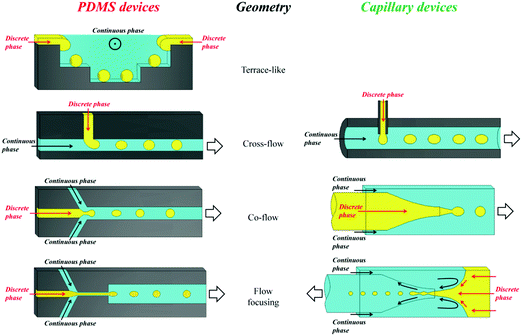
Emulsification can be carried out in PDMS devices and in capillary devices (Fig. 1). In the PDMS devices, both continuous and dispersed phases flow inside microchannels, while in the capillary ones the dispersed phase is introduced by a capillary of small dimensions inserted into the tube where the continuous phase flows.2.2. Flow photolithography based devices
Flow photolithography54 based devices employ a transparency mask which can be designed with various morphologies to polymerize and “print” the desired particle (Fig. 2). This technique relies on: (1) quick polymerization avoiding random shape deformation during irradiation and (2) oxygen permeation to form a thin oxygen inhibition layer in the PDMS microchannel avoiding the formation of sticky particles.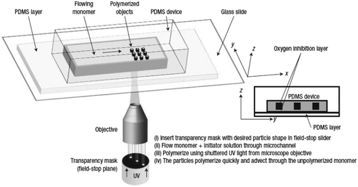 | ||
| Fig. 2 Scheme of continuous flow photolithography. Reproduced with permission from ref. 54. Copyright 2006 Nature Publishing Group. | ||
3. Fabrication methods of macroporous particles
Macroporous polymer resins have a permanent well-defined porous structure comprising pores in the size range of 10–10![[thin space (1/6-em)]](https://www.rsc.org/images/entities/char_2009.gif) 000 Å.53,55,96 Their preparation methods can be divided into 2 types: synthesis of monolithic resins and synthesis of particulate materials.2,97–108Table 1 compares several fabrication methods.
000 Å.53,55,96 Their preparation methods can be divided into 2 types: synthesis of monolithic resins and synthesis of particulate materials.2,97–108Table 1 compares several fabrication methods.
| Method (discovery) | Diameter of beads (μm) | Minimum CV of beads | Fabrication easiness/cost | Schematic illustration | Ref. |
|---|---|---|---|---|---|
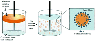
| Suspension polymerization (1920s) | 5–2000 | Very high | Easy/cheap |
|
55, 58, 59, 97 and 109–112 |
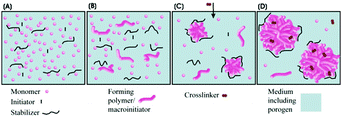
| Dispersion polymerization (1970s) | 0.1–20 | 2–3% | Easy/cheap |
|
55, 58, 59, 110, 111, 113 and 114 |
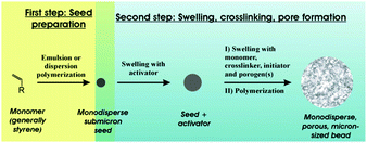
| Seeded suspension polymerization (1980s) | 0.5–200 | 2–3% | Cheap/time consuming |
|
55, 58, 97 and 110 |
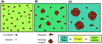
| Precipitation polymerization (1990s) | 0.1–8 | 2–3% | Easy/costly |
|
55, 58, 110, 111, 115 and 116 |
| Membrane/microchannel emulsification (1990s) | 10–1000 | 10% (membrane) or 2–3% (channel) | Difficult/costly |
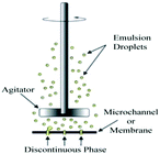
|
58, 117 and 118 |
| Microfluidics (2000s) | 10–1000 | <1% | Costly device |
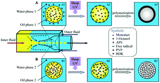
|
18, 69, 70, 76, 119 and 120 |
The resins can be applied either as porous monoliths99,102,121–123 or as porous beads.124 Rigid monoliths perform better in high-throughput separation processes and in catalytic reactions.2,98–103 Unfortunately, they suffer from high initial flow resistance and alter ions in the breakthrough curve. In contrast, the size distribution of particulate macroporous resins obtained by milling macroscopic materials to form irregular particles is controlled by subsequent fractionations.125 Though easy to fabricate, these particles show poor packing behavior and may block the column due to the presence of tiny secondary particles.97 Alternatively, heterogeneous techniques such as suspension polymerization can be practical and useful for the synthesis of microspheres with diameters in the range of 0.1–1.5 mm and relatively broad size distributions.12,55
Suspension polymerization53,55,96 and seeded emulsion polymerization104,105 are among the most common preparation methods. In the former, drops of a mixture of a monomer, an initiator and an inert solvent (porogen) are dispersed in the immiscible continuous phase aided by vibration jetting, stirring or sonication. Often, the residual porogen is more miscible with the monomer rather than with the polymer phase. Residual porogens and monomers can be removed by solvent extraction or steam distillation, while enhancing the particle porosity. Generally, particles <200 μm are obtained with a broad range of sizes, depending on the precise control of the emulsification process and the hindrance of droplet coalescence in the polymerization stage. In contrast, seeded emulsion polymerization can render polymer particles <50 μm with more narrow size distributions. This occurs in 2 steps:104–107 (1) quick swelling of monodisperse latex emulsions (seeds) followed by polymerization to solid particles and (2) removal of immiscible solvent residues to form a porous structure. Using seed particles with a low cross-linking degree is time-consuming, especially when particles >100 μm are envisioned. For macroporous particles with diameter <10 μm, precipitation polymerization in organic solvents can be used. For instance, toluene and xylene were used as co-solvents in acetonitrile to fabricate monodisperse highly cross-linked divinylbenzene particles.108
Advantages of microfluidic devices include low reagent consumption, facile mass/heat transfer, high safety and a high surface-area-to-volume ratio, with various outstanding features superior to conventional approaches.126–131 Most importantly, the size distribution of the macroporous particles obtained by microfluidic synthesis can be controlled more precisely thanks to the flow-focusing mechanism of monomer emulsification. Besides, on-chip continuous polymerization prevents droplet coalescence. Particles synthesized by microfluidic synthesis have a finer and more ordered internal structure. However, the generation of particles with diameters in the range of 50–100 μm employing microfluidic methods may be more challenging; particles fabricated by suspension polymerization132 show specific surface areas around 400 m2 g−1 compared to only 30 m2 g−1 for particles with the same composition obtained by the microfluidic technology.133
4. Microfluidic methods for the preparation of macroporous particles
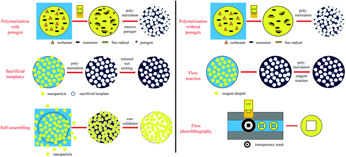
Recently, microfluidic techniques have been employed using single setup devices (lab-on-a-chip) to produce monodisperse porous particles.133,134 The microfluidic technique is an advanced version of conventional suspension polymerization, where monomer droplets are formed one by one in a controlled and reproducible manner. In general, droplet fabrication between 2 immiscible liquid phases can be obtained by various setups such as T-junction (also known as cross-flow135), flow focusing or co-flow geometries.81 By a precise selection of the discrete phase, various morphologies can be obtained including non-porous particles,126 capsules136 and porous particles.28,126,133,134 According to the pore formation mechanism, microfluidic methods are divided into 5 methods (Fig. 3): polymerization with/without porogens, sacrificial template, flow reaction, self-assembly and flow lithography. Besides, a detailed comparison between the different microfluidic-based porous particle fabrication methods is included (Table 2).| Microfluidic-based porous particle fabrication methods | Merits | Demerits | Applicability |
|---|---|---|---|
| Polymerization with porogens |
Wide universality
Wide variety of porogens |
Need post-processing to obtain a porous structure
Pores’ random distribution Unmanageable pore size |
Radially “opened” macroporous particles with regular shape |
| Polymerization without porogens | Without post-processing |
For specific phase component
Pores’ random distribution Unmanageable pore size |
Radially “skin” or “opened” macroporous particles with regular shape |
| Sacrificial templates |
Excellent pore shape
Uniform pore size |
Complicated process | Ordered or radially hierarchical porous particles with regular or irregular shape |
| Flow reaction | High porosity |
For specific phase component and reaction
Unstable pores’ formation |
Radially “skin” or “opened” macroporous particles with regular shape |
| Self-assembling | High porosity |
Unmanageable particle shape
Pores’ random distribution Unmanageable pore size |
Radially “opened” macroporous particles with regular or irregular shape |
| Flow photolithography |
Customized particle shape
Customized pore shape and distribution |
High cost of designed photomask
Low-yield |
Customized ordered or hierarchical porous particles with regular or irregular shape |
4.1. Radially macroporous particles
4.1.1.1. Smooth “skin” spheres. Smooth “skin” spheres have their surface covered with a thin dense layer with some small pores, if any. Ford et al.15 reported the formation of a dense and smooth layer when using (chloromethyl) styrene and divinylbenzene added in 4-methyl-2-pentanol. Detailed mechanistic information on particle formation lacked in the study. Pelzbauer et al.13 fabricated a similar architecture on the surface of poly(glycidyl dimethacrylate–ethylene methacrylate) macroporous particles when cyclohexanol or cyclohexanol–dodecanol was added as a porogen. They discovered that the formation of the smooth “skin” can be suppressed by tuning the polymer composition. Dubinsky et al.17 synthesized poly(glycidyl methacrylate–ethylene dimethacrylate) (poly(GMA–EGDMA)) droplets using dioctyl phthalate (DOP), diisodecyl phthalate (DDP) and their mixtures as porogens. Subsequently, the droplets were exposed to UV-irradiation for 60 s on-chip and 180 s off-chip after polymerization. Then, the porogen liquids were removed by washing microparticles with methanol and acetone. They observed smooth “skinned” surfaces and had some control over the internal particle structure (Fig. 4).
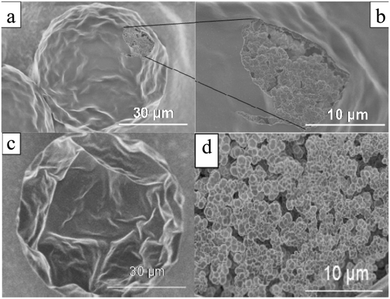 | ||
Fig. 4 SEM images of (a and c) surface and (b and d) internal structure of “skin” macroporous poly(GMA–EGDMA) particles, synthesized in the presence of (a and b) DBP/DOP 1![[thin space (1/6-em)]](https://www.rsc.org/images/entities/char_2009.gif) : :![[thin space (1/6-em)]](https://www.rsc.org/images/entities/char_2009.gif) 1 (v/v) and (c and d) DOP (0.5 wt% Triton X-100). Reproduced with permission from ref. 17. Copyright 2009 American Chemical Society. 1 (v/v) and (c and d) DOP (0.5 wt% Triton X-100). Reproduced with permission from ref. 17. Copyright 2009 American Chemical Society. | ||
The employment of porogens leads to porosity development,18,138 but it imposes an extra step for the removal of these agents. Watanabe et al.139 reported the controlled preparation of polyelectrolyte particles in the 10–100 μm range through selective solvent extraction in a cross-flow microfluidic device. Mixtures of poly(styrene sulfonate) and water (dispersed phase) were introduced into the T-junction to form plugs in hexadecane (continuous phase). Subsequently, the obtained plugs were introduced into methyl ethyl ketone which is miscible with hexadecane and water but not with poly(styrene sulfonate) in a flow-focusing microchannel (in situ precipitation) or in a prepared vessel (ex situ precipitation) (Fig. 5a and b). Smooth “skin” macroporous particles were obtained (Fig. 5c) with a gradient internal porous structure (Fig. 5d).
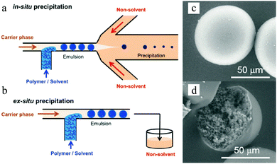 | ||
| Fig. 5 (left) Illustration of (a) in situ and (b) ex situ preparation via microfluidic emulsification, precipitation and solvent extraction. (right) SEM images of the (c) smooth “skin” surface and (d) internal structure. Reproduced with permission from ref. 139. Copyright 2014 American Chemical Society. | ||
Besides, Sim et al.140 fabricated microparticles whose top or side surface was not flat but curved, such as circular, square, triangular and stellate microdisks (Fig. 6a–d), by introducing a novel double-layered PDMS microfluidic device, combining conventional photolithography and multilayer soft-lithography (microfluidic molding). Two straight control channels, used for pneumatic actuation of the membrane to mold and release the particles, were situated on the top layer while a T-junction channel, used for suspension flow, was integrated in the bottom layer. Interestingly, by controlling the pressurization in the top channel, the membrane was either deformed to confine the suspension into the designed shape and then polymerized by UV-irradiation or recovered to the original shape by releasing the obtained particles. Finally, microparticles could exit through the bottom channel.
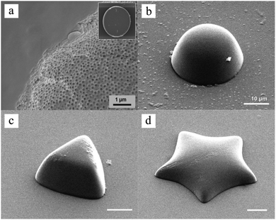 | ||
| Fig. 6 SEM images of (a) broken porous microparticles with a smooth surface and internal porous structure, (b) hemispherical microparticles, (c) triangular microparticles with an inclined side wall and (d) stellate microparticles with a curved surface. Scale bars are 1 μm (a) and 10 μm (b–d). Reproduced with permission from ref. 140. Copyright 2014 Wiley-VCH. | ||
The cycle of molding, polymerization and particle release could only be achieved by pneumatic force in the microfluidic device. By introducing a photo curable suspension of silica nanoparticles in the microfluidic molding process and subsequent selective wet-etching of the silica nanoparticles with a HF solution, a polymerized matrix with regular pores and structural colors was obtained.
Unlike the works of Pelzbauer et al.13 and Dubinsky et al.17 in which porogens were used to obtain closed macroporous particles, more recently, Udoh et al.141 employed a microfluidic solvent extraction approach to prepare “skin” polymer particles (Fig. 7). At the same time, they also deeply investigated the effect of polymer solution thermodynamics in the particle fabrication process by comparing two different non-solvents (ethyl acetate (EA) and methyl ethyl ketone (MEK)) in the extraction of a polymer/solvent (NaPPS/H2O) system. The outstanding control of particle size and closed porous structure verified that the solvent extraction method is more convenient than ones that need conventional porogens or a complex post-processing process.
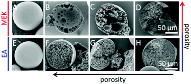 | ||
| Fig. 7 SEM images of (A and E) external surface and (B–D and F–H) cross sections of “skin” polymer particles obtained by extraction in MEK and EA. (A, C, E and G) CNaPSS;t=0 = 3.5 wt%, (B and F) CNaPSS;t=0 = 1.0 wt%, (D and H) CNaPSS;t=0 = 10 wt%. Reproduced with permission from ref. 141. Copyright 2016 American Chemical Society. | ||
4.1.1.2. Golf-ball-shaped particles. Golf-ball-shaped microparticles142–144 show dimple surface patterns or internal pore structures and therefore have larger surface areas than smooth microparticles. Therefore they improve the adhesion and prolong the distance of flight by reducing the air drag force.145–148 Conventional fabrication methods include:142,143,149–154 (1) seeded dispersion/emulsion polymerization and (2) emulsion stabilization using small colloidal particles. However, the former techniques cannot be applied in biological systems (toxicity) and the latter one lacks precise control of the particle internal architecture. Microfluidic methods have emerged as a versatile alternative for this type of microparticles. Kim et al.155 used photocurable suspended droplets containing colloidal silica nanoparticles. The surface of these monodisperse emulsion droplets, obtained from 2 coaxial glass capillaries with different diameters,156 was decorated with a hexagonal array of silica particles. After UV-irradiation for 1 s, raspberry-like microparticles154,157 were obtained and transformed to golf-ball-shaped structures (Fig. 8) by etching away the silica nanoparticles on the surface of the raspberry-like microparticles using either 1 wt% NaOH or 5 wt% HF.
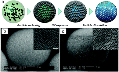 | ||
| Fig. 8 (a) Illustration of the fabrication steps of golf-ball-shaped microparticles. SEM images including close-up of microparticles with arrays of 235 nm silica nanoparticles (b) before and (c) after the wet etching process. Scale bars in (b) and (c) are 20 μm, while 1 μm in close-up images. Reproduced with permission from ref. 155. Copyright 2009 IOP Publishing Ltd and Deutsche Physikalische Gesellschaft. | ||
In the same year, Kim et al.158 adapted the technique for the controlled fabrication of hemispherical golf-ball-shaped structures or so-called photonic domes by using photocurable emulsion droplets as templates.156 The patterned polymeric domes (Fig. 9) were prepared in 3 steps: (1) fabrication of ethoxylated trimethylolpropane triacrylate (ETPTA) droplets containing a high load of silica nanoparticles, (2) UV-irradiation of droplets for 10 s inducing polymerization and (3) selective removal of silica nanoparticles on the surface by a HF solution.156,159 Kim et al.160 added a post-treatment of these golf-ball-shaped microparticles by reactive ion etching with sulfur hexafluoride resulting in microparticles composed of super hydrophobic and hydrophilic surfaces.
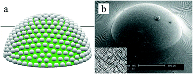 | ||
| Fig. 9 (a) Illustration of patterned polymeric domes, (b) SEM image of a single polymeric dome, including magnification of the porous surface morphology. Scale bar is 100 μm. Reproduced with permission from ref. 158. Copyright 2009 Wiley-VCH. | ||
Hwangbo et al.161 proposed a novel method to obtain microparticles with both a golf-ball-shaped surface and an internal porous structure using various polymers in a one-pot method (no post-treatment), similar to the breath figure method.148 In their fabrication process, an inert organic volatile phase change material (PCM) was employed, e.g. dichloromethane (DCM). Dimple patterns were created already in the first stage by fast DCM evaporation (Fig. 10a).
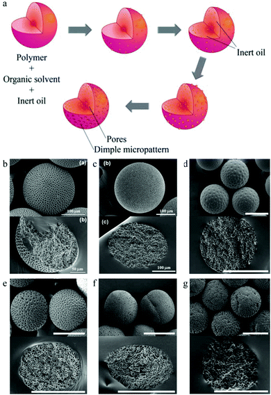 | ||
| Fig. 10 (a) Illustration of golf-ball-shaped microparticle fabrication. SEM images of the surface (up) and internal structure (down) using (b) poly(D,L-lactide-co-glycolide) (PLGA), (c) poly(methyl methacrylate) (PMMA), (d) polysulfone (PSf), (e) poly(D,L-lactide) (PDLA), (f) poly(L-lactide) (PLLA) and (g) poly(ε-caprolactone) (PCL). Scale bars are 50 μm (b, down), 100 μm (b, up and c) and 200 μm (d–g). Reproduced with permission from ref. 161. Copyright 2011 The Royal Society of Chemistry. | ||
Along with DCM evaporation, phase separation between the polymer and PCM led to PCM droplet formation inside the oil droplets. The particle solidification process was accompanied by volume shrinkage. Eventually, surface dimples formed on the PCM surface covering the oil phase droplet, while the PCM inside the oil phase droplet contributed to form a closed porous structure. Soft stirring of the aqueous medium before surface solidification generated smaller and more even dimples. Interestingly, the SEM images (Fig. 10b–g) showed that the golf-ball-shaped microparticles exhibited a dimple surface pattern with no pores using amorphous polymers (PSf and PDLA), while the ones obtained with semi-crystalline polymers (PLLA and PCL) contain surface pores.
Based on Hwangbo et al.'s work, Lee et al.162 could enhance the diameter of the surface dimples (thereby lowering the specific number of dimples) by increasing the PCM to PLGA ratio in the same tube-type microfluidic device (Fig. 11). A subsequent study found that because of this unique structure, active agents can be released faster from surface dimples than from interior dimples, which opened routes for drug release strategies. Compared to hollow and open porous microparticles, golf-ball-shaped ones can avoid interference from the external environment with the internal encapsulated material.
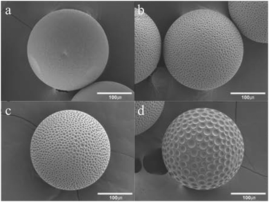 | ||
Fig. 11 SEM images of golf-ball-shaped microparticles with PLGA![[thin space (1/6-em)]](https://www.rsc.org/images/entities/char_2009.gif) : :![[thin space (1/6-em)]](https://www.rsc.org/images/entities/char_2009.gif) PCM ratios of (a) 9 PCM ratios of (a) 9![[thin space (1/6-em)]](https://www.rsc.org/images/entities/char_2009.gif) : :![[thin space (1/6-em)]](https://www.rsc.org/images/entities/char_2009.gif) 1, (b) 8 1, (b) 8![[thin space (1/6-em)]](https://www.rsc.org/images/entities/char_2009.gif) : :![[thin space (1/6-em)]](https://www.rsc.org/images/entities/char_2009.gif) 2, (c) 7 2, (c) 7![[thin space (1/6-em)]](https://www.rsc.org/images/entities/char_2009.gif) : :![[thin space (1/6-em)]](https://www.rsc.org/images/entities/char_2009.gif) 3 and (d) 6 3 and (d) 6![[thin space (1/6-em)]](https://www.rsc.org/images/entities/char_2009.gif) : :![[thin space (1/6-em)]](https://www.rsc.org/images/entities/char_2009.gif) 4. Reproduced with permission from ref. 162. Copyright 2014 American Chemical Society. 4. Reproduced with permission from ref. 162. Copyright 2014 American Chemical Society. | ||
4.1.2.1. Macroporous spheres. Polymeric cryogels, which are sponge-like materials with a super macroporous structure, are of interest as new chromatographic supports, cell scaffolds and drug carriers in biological and biomedical areas. In general, the matrices of the gels are prepared in the form of monoliths by polymerization under cryogenic conditions. Alternatively, the cryogels can be produced in the form of suitable adsorbent microspheres. Yun et al.168 provided a novel approach by combining the microchannel flow focusing technique with cryo-polymerization for the preparation of polyacrylamide-based gel microspheres with narrow particle size distribution (Fig. 12).
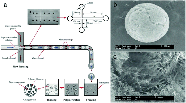 | ||
| Fig. 12 (a) Illustration of the cryo-polymerization process for the synthesis of macroporous microspheres. SEM images of (b) surface morphology and (c) internal structure. Scale bars are 500 μm (b) and 50 μm (c), respectively. Reproduced with permission from ref. 168. Copyright 2012 Elsevier B.V. | ||
Dubinsky et al.133 reported a semi-continuous photo-initiated microfluidic synthesis method of macroporous polymer microspheres in the size range of 10–100 μm with narrow size distribution. Monodisperse droplets were obtained with different compositions by employing different porogens: diethyl phthalate (DEP), diisobutyl phthalate (DBP), dioctyl phthalate (DOP) and diisodecyl phthalate (DDP), followed by UV-induced polymerization and washing with methanol and acetone for porogen removal (Fig. 13). The surface of the microspheres had a well-defined and interconnected porous structure, depending on the type of porogen used. The mean particle diameter increased in the order DEP < DBP < DOP < DDP, while the specific surface area decreased in the same order. Dubinsky et al.17 added variations to this preparation method by applying not only different porogens, but also their mixtures. Fig. 14 shows the surface morphology and the internal structure of macroporous poly(GMA–EGDMA) particles using a DBP![[thin space (1/6-em)]](https://www.rsc.org/images/entities/char_2009.gif) :
:![[thin space (1/6-em)]](https://www.rsc.org/images/entities/char_2009.gif) DOP (3
DOP (3![[thin space (1/6-em)]](https://www.rsc.org/images/entities/char_2009.gif) :
:![[thin space (1/6-em)]](https://www.rsc.org/images/entities/char_2009.gif) 1 v/v) mixture as a porogen. Interestingly, the interconnected morphology remained, but the surface morphology changed to porous or smooth. Additionally, they built a map (Fig. 15) demonstrating the relationship between the solubility parameter and the interfacial tension “map”, which predicts the surface morphology as a function of the monomer and porogen.
1 v/v) mixture as a porogen. Interestingly, the interconnected morphology remained, but the surface morphology changed to porous or smooth. Additionally, they built a map (Fig. 15) demonstrating the relationship between the solubility parameter and the interfacial tension “map”, which predicts the surface morphology as a function of the monomer and porogen.
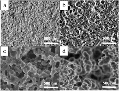 | ||
| Fig. 13 SEM images of surface morphology of macroporous microspheres prepared with (a) DEP, (b) DBP, (c) DOP and (d) DDP as porogens. Scale bar is 500 nm. Reproduced with permission from ref. 133. Copyright 2008 American Chemical Society. | ||
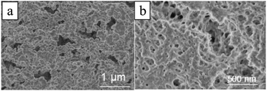 | ||
Fig. 14 SEM images of the (a) internal structure and (b) surface morphology of macroporous microbeads, generated with mixtures of DBP![[thin space (1/6-em)]](https://www.rsc.org/images/entities/char_2009.gif) : :![[thin space (1/6-em)]](https://www.rsc.org/images/entities/char_2009.gif) DOP 3 DOP 3![[thin space (1/6-em)]](https://www.rsc.org/images/entities/char_2009.gif) : :![[thin space (1/6-em)]](https://www.rsc.org/images/entities/char_2009.gif) 1 (v/v). Reproduced with permission from ref. 17. Copyright 2009 American Chemical Society. 1 (v/v). Reproduced with permission from ref. 17. Copyright 2009 American Chemical Society. | ||
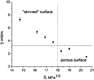 | ||
| Fig. 15 Map of interfacial tension (γ) and solubility parameter (δ) of porogens using a 2.5 wt% aqueous solution as the continuous phase and different porogen solvent compositions as the dispersed phase. Reproduced with permission from ref. 17. Copyright 2009 American Chemical Society. | ||
Kim et al.156 introduced a two-step method composed of photopolymerization and wet etching for the synthesis of porous photonic spheres in a co-flow capillary device (Fig. 16a). Interestingly, the pores packed on the outer layer showed well-ordered arrays, while near the core the structure became less ordered due to the high curvature. By tuning the diameters of the embedded silica particles from 145 to 152 and 190 nm, the emulsion droplets exhibited different colors from blue to green and red, opening potential application in optical research.
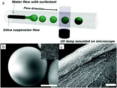 | ||
| Fig. 16 (a) Illustration of uniform droplets generated in the microfluidic device. SEM images of (b) whole photonic sphere embedded with 165 nm silica particles and (c) porous surface of the sphere. Reproduced with permission from ref. 156. Copyright 2008 Wiley-VCH. | ||
The introduction of porosity in microbeads requires porogens which are emulsified with other microbead components during the synthesis. To produce the pores effectively, porogens must be removed in a second leaching process, which requires harsh conditions. Therefore, the removal may be assisted by taking away the encapsulated active compounds also.173,174 This limitation can be overcome by using new miscible porogens or new synthesis strategies, like those that employ permanent geometric templates or scaffolds to avoid the leaching step.175–177 Duncanson et al.169 introduced a self-assembling perfluorinated–dendrimer–dye complex as a novel pore forming agent to generate monodisperse macroporous microspheres (Fig. 17) in a microfluidic flow-focusing device (FFD). After removing the organic solvent, residual water and gas were released from the microspheres under vacuum conditions followed by further drying and solidification of the droplets. The porogen not only acted as a pore formation agent, but also played a role as a carrier for additional active materials. It encapsulated efficiently active materials avoiding their disruptive removal. These microbeads could be applied in liquid–gas mixtures.
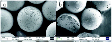 | ||
| Fig. 17 SEM micrographs of macroporous microspheres made by using the (a) [G 1.5]–dye complex and (b) [G 3.5]–dye complex. Reproduced with permission from ref. 169. Copyright 2012 The Royal Society of Chemistry. | ||
Jiang et al.178 created a new type of discrete immunebeads using microfluidic microspheres. Three interesting features are associated with their synthesis route: (1) SR454 serving as a trivinyl cross-linker increased the pore dimensions and therefore enhanced the transport and exchange of biomolecules, (2) decyl alcohol was adopted as a safer porogen rather than conventional phthalate plasticizers, without compromising the precise control of the final pore morphology and (3) the microfluidic apparatus was simple and cheap compared to conventional ones.77,179,180 The immune active ligands were first decorated on the porous surface followed by macropore formation (Fig. 18a). The proteins (anti-IgG) were anchored on the porous surface with 2 separate processing routes, using either glutaraldehyde (GLU) or N-gamma-maleimido-butyryloxy-succinimide (GMBS). In the former, the GMA surface epoxides were reacted first with ethylenediamine and then consented with GLU through aldehyde–amine interaction (Fig. 18b).181 The remaining free aldehyde group on GLU was then reacted with IgG primary amines to decorate the antibodies on the polymer surface.182 Some interference was observed due to background fluorescence and unsaturated imine formation. In the GMBS procedure, a thiol group was first grafted onto the monolith via epoxide–cysteamine reaction. Subsequently, GMBS was anchored on the newly formed thiol group, by reacting with the GMBS maleimide terminus. The auto fluorescence interference was repressed in this procedure. As a result, the microspheres grafted with bioactive proteins gradually evolved to discrete immune sensor elements.
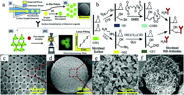 | ||
| Fig. 18 Illustration of (a) macroporous microsphere fabrication and surface modification for ligand anchoring, (b) GMBS and GLU approaches for anchoring an antibody on the polymer surface and (c) optical image of the macroporous microspheres. SEM images of the (d) whole microsphere, (e) macroporous surface and (f) cleaved microspheres showing a uniform and cellular structure throughout the whole particle. Reproduced with permission from ref. 178. Copyright 2012 Elsevier Ltd. | ||
Emulsion templating is among the most convenient and commonly used macroporous microparticle fabrication methods. By fabricating monomer-comprised single emulsions as templates in a microfluidic device, with appropriate initiators and different types of porogens, microspheres can be controllably prepared with a monodisperse and highly interconnected structure. Zhang et al.18 proposed a novel and simple method to prepare monodisperse poly(HEMA–MMA) microbeads with macroporous structures, using oil-in-water (O/W) emulsions as templates with 2,2-dimethoxy-2-phenylacetophenone as a photo-initiator and poly(vinyl pyrrolidone) (PVP) as a porogen in a flow-focusing capillary microfluidic device.81,183 The microbeads showed slow biodegradability, increased chemical stability due to their polymeric 3D networks (formed after free radical co-polymerization of MMA with 2-hydroxyethyl methacrylate (HEMA))184 and high specific surface area. SEM images (Fig. 19) illustrate that upon altering the [PVP]/([HEMA] + [MMA]) mass ratio, the final morphology of microspheres varied significantly. Remarkably, the mechanical strength decreases with increasing contents of PVP.
 | ||
| Fig. 19 SEM images of macroporous poly(HEMA–MMA) microspheres with PVP/(HEMA + MMA) wt% of (a) 3%, (b) 5% and (c) 7%. Scale bar is 20 μm. Reproduced with permission from ref. 18. Copyright 2009 Elsevier Inc. | ||
High-internal-phase emulsion (HIPE) is another emulsion templating method,185–189 where the volume fraction of the dispersed phase exceeds the 0.74 threshold value for monodisperse emulsions and can reach up to 0.99. PolyHIPE beads contain larger cavities within an average size range of 10–100 μm. These cavities are interconnected by a series of smaller pores that enable them to communicate with the adjacent ones. For their fabrication, first water, an initiator and a salt were mixed together for the formation of the interior phase. Then, this interior phase was mixed with the organic phase and an emulsifier to constitute a water-in-oil (W/O) HIPE. Finally, after polymerization of the continuous phase and removal of the aqueous droplets, porous particles with spherical geometry were obtained190–194 under controlled conditions. Gokmen et al.19,195,196 also fabricated poly(HIPE) microspheres using a microfluidic approach. Both dimension and morphology of the microspheres were precisely controlled. The obtained beads showed significantly smaller pore diameter, even down to 15 μm (Fig. 20). A post-modification was also demonstrated to modify the chemical functionality of the internal structure.
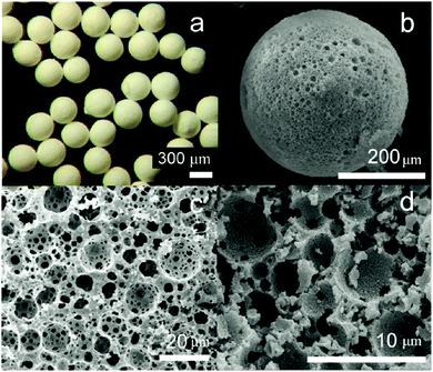 | ||
| Fig. 20 (a) Optical microscopy images of porous poly(HIPE) beads. SEM images of (b) whole microspheres, (c) surface of a microsphere and (d) inner structure of the microspheres. Reproduced with permission from ref. 19. Copyright 2009 American Chemical Society. | ||
Double emulsions such as water-in-oil-in-water (W–O–W) and oil-in-water-in-oil (O–W–O) are complex colloidal systems, where dispersed droplets contain smaller droplets. They are potential devices to encapsulate active substances, e.g. cosmetics,197 drugs,198–200 living cells,201 and food supplements.202,203 Stable double emulsions can be fabricated in fluidic devices based on microchannels, both in PDMS devices and in capillaries. Two-step droplet break-up at the T-junction204,205 and hydrodynamic flow focusing79,128,206,207 were the common setups used. The double emulsions often rendered excellent characteristics, such as uniformity in terms of diameter, shape, wall thickness and the number of encapsulated droplets. Moreover, simple fluidic devices constructed from glass capillary tubes, needles and PVC tubes were also developed for this purpose.196,208–210 Choi et al.175 introduced a fluidic device with one extra fluid channel in the above described system (3 flow channels totally), yielding uniform double emulsions (Fig. 21a). In this W–O–W system, both the W–O emulsion obtained in the first step and the W–O–W emulsion obtained after the second step were prepared in a dripping mode, leading to more uniform dimensions than those obtained in a jetting mode.211,212 The W–O–W emulsion droplets evolved gradually to large interconnected pores (Fig. 21b and c). This method was employed in numerous studies.192,213–215
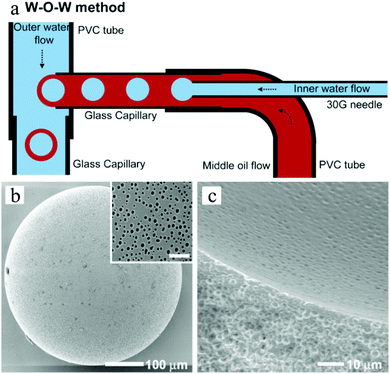 | ||
| Fig. 21 (a) Illustration of the microfluidic apparatus for W–O–W emulsions. SEM images of (b) the porous surface including a close-up (scale bar is 5 μm) and (c) the cross-sections and the internal structure of PLGA microbeads. Reproduced with permission from ref. 175. Copyright 2009 Wiley-VCH. | ||
Jeong et al.170 created photo- and thermoresponsive macroporous core–shell spheres with reversible membrane permeability using a simple microfluidic device (Fig. 22). Highly uniform W–O–W double emulsion droplets with an aqueous core and interconnected porous shell were generated as templates, whose outer layer is then covered with an ethyl cellulose membrane with densely packed poly(N-isopropylacrylamide) (pNIPAAm) nanoparticles containing gold rods, which endowed the macroporous spheres with thermoresponsivity. The size of the pores was in the range of submicrometers to several micrometers. The ethyl cellulose membrane aided in the mechanical strength and was hardly affected by light, heat and chemicals. Interestingly, the permeability of the pNIPAAm nanoparticle embedded membrane was regulated by temperature, as a function of its phase transition behavior. When the temperature was raised beyond a certain value, the microspheres shrunk and start to allow much bigger molecules to pass through. This feature would not be achieved without the gold nanorods on the microspheres. By using near-infra-red (NIR) irradiation, the reversible membrane permeability could be remote controlled.
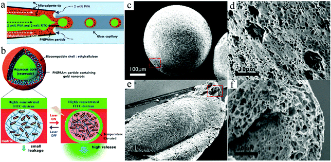 | ||
| Fig. 22 Illustration of (a) the fabrication and (b) the structure of macroporous core–shell pNIPAAm microspheres with the corresponding SEM images of (c and d) porous surface and (e and f) cross-sections. Reproduced with permission from ref. 170. Copyright 2013 American Chemical Society. | ||
Next to single and double emulsion templates, a three phase emulsion was used by Wan et al.134 to produce porous polyacrylamide microspheres. The emulsion consisted of gas, water and oil, applied in flow focusing or T-junction devices, FFD (Fig. 23a) and FFT (Fig. 23b), respectively. Individual gas bubbles were encapsulated by monodisperse photopolymerizable acrylamide (AAm) aqueous droplets (Fig. 23c). After UV-irradiation, these droplets gradually evolved to highly porous microspheres. The gas pressure played a major role in the droplet size in the FFT device, but it was only marginally affected in the DFF device.
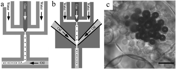 | ||
| Fig. 23 Illustration of the (a) DFF and (b) FFT microchannel geometry of the microfluidic apparatus and (c) optical image of microspheres from three-phase emulsions (scale bar is 50 μm). Reproduced with permission from ref. 134. Copyright 2008 Wiley-VCH. | ||
The formation of macropores by reaction between reagents, e.g. thiol–ene and thiol–yne reactions,216,217 has become an attractive alternative because it omits tedious templates and porogen removal procedures. Prasath et al.164 presented a method to apply thiol–ene and thiol–yne reactions followed by UV-induced polymerization in a simple co-flow capillary device as a one-step preparation procedure of macroporous microspheres containing different functional groups with different morphologies (Fig. 24). Li et al.218 improved this strategy by two reactions occurring successively in a single droplet: an exothermic free radical polymerization of an acrylate monomer followed by an endothermic polycondensation with a urethane oligomer, activated by the heat generated from the first reaction. As a result, an interpenetrating polymer network is obtained within the macroporous structure.
 | ||
| Fig. 24 SEM images of (a1–d1) whole microparticles and (a2–d2) surface morphology of macroporous microparticles generated from the “thiol–ene” formation of (a1 and a2) TT/(DAP + AA)α, (b1 and b2) TT/(DAP + AA)β, (c1 and c2) TT/PTEβ and (d1 and d2) (TT + MA)/TTTβ. SEM images of (e1 and f1) whole microparticles and (e2 and f2) relative surface morphology from the “thiol–yne” formation of (e1 and e2) TT/(OY + PA)β and (f1 and f2) TT/(OY + DPPD)β. Reproduced with permission from ref. 164. Copyright 2010 The Royal Society of Chemistry. | ||
As a variation of this method, Gong et al.163 prepared porous beads via simultaneous reactions within a single droplet in a microfluidic FFD. Monodisperse droplets, containing a H2O2 solution, were fabricated with several precursors: NOA 61 (a mixture of trimethylolpropane diallyl ether, isophorone diisocyanate ester, trimethylolpropane tris thiol and a benzophenone photo-initiator),219–222 EGDMA or tripropylene glycol diacrylate (TPGDA).127,223 The droplets were further encapsulated in the outer phase (either liquid paraffin for NOA 61 or silicon oil for EGDMA and TPGDA) and exposed to UV-irradiation until the desired number of cores was generated. The UV-light and/or heat induced the polymerization of the shell and the decomposition of H2O2, and the precursors were solidified while oxygen and water vapor (after further heating) were released through the shell creating a porous structure (Fig. 25). These porous microspheres had a pore dimension in the range of 1–100 μm and a maximum internal void volume fraction up to 70%, similar to the HIPE microbeads.
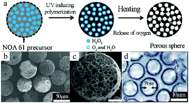 | ||
| Fig. 25 (a) Illustration of the structural evolution from emulsion to macroporous microspheres. SEM images of (b and c) polyTPGDA microspheres and (d) cross-section of polyNOA microspheres. Scale bar is 50 μm (c). Reproduced with permission from ref. 163. Copyright 2009 American Chemical Society. | ||
The microfluidic technology provides a method to precisely control the fabrication of porous beads. However, microfluidic devices are often limited in channel size and therefore complications may arise when materials are difficult to solidify, e.g. when they are light/heat sensitive or absorb light too strongly. Photopolymerization or photo cross-linking can help the precursors to react and solidify more rapidly. Superparamagnetic porous microbeads can be subjected to an external magnetic field to simplify the particle separation process.224–226 Moreover, particles can be selected on the basis of size and magnetic susceptibility in miniaturized on-chip systems.227 They are fabricated with porogens or double emulsions in microfluidic channels with good control over size and distribution.17–19,58,133,134,163,228
However, superparamagnetic iron oxide nanoparticles (SPIONs) absorb light strongly, thus being more difficult to photopolymerize. Paquet et al.167 addressed this limitation by preparing superparamagnetic microbeads based on the assembly of materials rather than any other chemical transformation such as polymerization or cross-linking, so making it suitable for fabrication with materials which are sensitive to light or heat. Different microbead morphologies resulted from alterations in the assembly processes, depending on the rate of solvent depletion from the droplet, the absorption of sodium dodecyl sulfate (SDS) at the droplet interface and the solubility of the SPIONs in the droplet phase. By adjusting the SDS concentration (Fig. 26a–d) and the polarity of the disperse phase (Fig. 26e–h), the porosity gradually evolved from non-porous to a dense and opened cellular structure. Wacker et al.166 combined evaporation-induced solidification and silica nanoparticle self-assembly to fabricate porous microspheres. Upon changing the nanoparticles’ dimension from 50 to 500 nm, the porous microspheres present different surface morphologies (Fig. 27). Their hypothesis states that if the pores were too small, evaporation of water to vapor affected the final morphology resulting in wrinkled surfaces. In contrast, when the pores were wide enough, the water vapor passed through the surface without any obstacle.
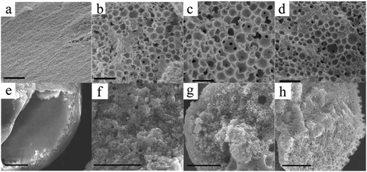 | ||
Fig. 26 SEM images of the internal structure of the macroporous microbeads collected in (a) 0, (b) 25, (c) 50 and (d) 100 mM SDS solutions, and of the microbead interior using (e) chloroform, (f) THF![[thin space (1/6-em)]](https://www.rsc.org/images/entities/char_2009.gif) : :![[thin space (1/6-em)]](https://www.rsc.org/images/entities/char_2009.gif) toluene mixture (3 toluene mixture (3![[thin space (1/6-em)]](https://www.rsc.org/images/entities/char_2009.gif) : :![[thin space (1/6-em)]](https://www.rsc.org/images/entities/char_2009.gif) 2), (g) toluene and (h) hexane as the dispersed phase. Scale bars are 1 μm (a–d) and 10 μm (e–h). Reproduced with permission from ref. 167. Copyright 2012 American Chemical Society. 2), (g) toluene and (h) hexane as the dispersed phase. Scale bars are 1 μm (a–d) and 10 μm (e–h). Reproduced with permission from ref. 167. Copyright 2012 American Chemical Society. | ||
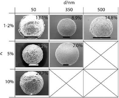 | ||
| Fig. 27 SEM images of porous spheres assembled by silica nanoparticles with increasing diameter (d/nm) and colloid weight concentrations (c). Scale bars are 10 μm. Reproduced with permission from ref. 166. Copyright 2011 American Chemical Society. | ||
4.1.2.2. Macroporous irregular microstructure. Non-spherical particles are rather difficult to fabricate in microfluidic devices due to their high droplet surface tension and their microchannel geometry. Therefore, stabilizers are added to reduce the surface tension, combined with a meticulously designed confined space which determines the final particle shape. Both spherical and non-spherical shapes were obtained by Gokmen et al.19 The non-spherical shape of poly(HIPE) particles was rather difficult to reproduce. This was dramatically improved by applying a different HIPE formulation,229 resulting in the reproducible fabrication of porous rods (Fig. 28). For this, (PEO–PPO–PEO) 4000 was used as a surfactant instead of (PEO–PPO–PEO) 2800. The poly(HIPE) porous rods had a diameter of around 0.2 mm, which was considerably smaller than the 0.8 mm inner diameter of the continuous channel, suggesting that the viscosity of the dispersed phase regulated the final shape rather than the microchannel geometry.
 | ||
| Fig. 28 (a) Optical microscopy of poly(HIPE) rods. SEM images of (b) partial rod and (c) porous surface of a rod. Reproduced with permission from ref. 19. Copyright 2009 American Chemical Society. | ||
Wacker et al.166 also obtained rod-like micro-objects, deformed from porous spheres (Fig. 29), in this case by evaporation-induced solidification and silica particle self-assembly. Increasing the oscillation time resulted in more elongated shapes and a too high oscillation frequency led to smaller clusters rather than porous rod-like structures.
 | ||
| Fig. 29 SEM images of porous rod-like particles. Reproduced with permission from ref. 166. Copyright 2011 American Chemical Society. | ||
Important in view of possible applications, the morphology of microgels directly affected the response rate to external stimuli. For instance, conventional poly(N-isopropylacrylamide) PNIPAAm microgels usually showed a homogeneous but disconnected internal structure, which slowed down the response rate.230,231 Several attempts were made to improve the response rate of microgels, such as constructing a more heterogeneous internal structure,231–235 grafting functional groups onto the microgels236,237 or employing different porogens to improve the porosity,238–240 albeit with only moderate success. But, Chu and co-workers183 generated monodisperse pNIPAAm microgels with spherical voids via embedding solid polystyrene microbeads inside and then dissolving them with xylene, giving significantly improved response rates. Huang and his team241 also successfully fabricated pNIPAAm microgels with a good porous structure and response rate, using polyethylene glycols as porogens. Yue et al.242 improved their response rate as well, but by introducing nanogels into the microgels. Still, these fabrication methods are tedious.
pNIPAAm microcapsules can shrink upon exposure to external stimuli like heating and to certain chemicals, which finally ruptures the hydrogel surface membrane, while the oil cores inside the microcapsules squeeze out.243–246 Based on this, Mou et al.171 fabricated environmental stimuli-responsive microgels with a highly interconnected open cellular structure by combining homogeneous emulsification and polymerization by UV-irradiation (Fig. 30). The initial homogeneous O/W emulsions served as the inner phase and soybean oil with 5% w/v PGPR as the outer phase, which were successively injected into a co-flow capillary device to obtain monodisperse (O/W)/O emulsions. Upon exposure to UV-irradiation in an ice-water bath, followed by addition of isopropanol or heating, pNIPAAm microgels with open internal structures were obtained through volume shrinkage of the microgels. They compared them with microgels obtained under identical conditions but with conventional emulsions, where the aqueous phase replaced the O/W emulsion. The (O/W)/O directed microgels exhibited a much higher response to environmental stimuli, such as temperature, pH, etc.247–249 These results make them attractive for application in sensors, separations and actuators.250,251
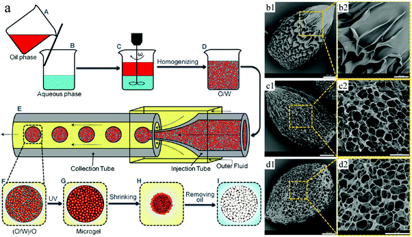 | ||
| Fig. 30 (a) Illustration of porous pNIPAAM microgel formation. SEM images of pNIPAAm microgels obtained with (b1 and b2) W/O emulsions and (c and d) (O/W)/O emulsions, with molar ratios of MBAAm to NIPAM of (c1 and c2) 2% and (d1 and d2) 4%. Scale bars are 50 μm (b1, c1 and d1) and 20 μm (b2, c2 and d2). Reproduced with permission from ref. 171. Copyright 2014 American Chemical Society. | ||
Thin membranes can be fabricated in a microfluidic system, by cherry-picking the immiscible solutions and precisely tuning the viscosity to attain laminar flows, followed by polymerization at the liquid–liquid interface. However to date, thin membranes formed using conventional approaches have very small pore size and sometimes even lack pores, which limits their use in biological applications such as cell migration and molecule detection. Based on the study of surface tension and laminar flow behavior,252–254 an in situ fabrication method was reported by Kim and Beebe,255 relying on the interfacial reaction of a two-phase system to produce a porous nylon membrane with pore dimensions 0.1–1 μm (Fig. 31c–e). This approach made it possible to generate very thin porous membranes, firmly fixed inside the microchannel without any other bonding process. As shown in Fig. 31a, 2 partially separated microchannels existed in the fluidic apparatus.252–254 After washing one microchannel with hexadecane and the other one with a mixture of hexadecane and octadecyl trichlorosilane, the 2 microchannels turn hydrophilic and hydrophobic, respectively. Then an aqueous solution and organic solution, respectively, were introduced into the microchannels. 1,6-Diaminohexane in water and adipoyl chloride in toluene reacted at the interface resulting in a membrane. After 15 min, the aqueous and organic solutions are replaced with MeOH and toluene, respectively, followed by washing and drying. Most of the PEG (poly(ethylene glycol) was removed with the aqueous phase as it is highly soluble in water. Fig. 31b shows that different morphologies existed on both sides (asymmetric membrane). The organic side showed a ridge-and-valley structure (2–5 μm), while the aqueous side had a smooth skin surface (about 0.5 μm). Thus, the polymer transport occurred from the aqueous solution side to the organic solution side. This technique was also employed for the formation of chitosan and polycarbonate porous membranes.256,257
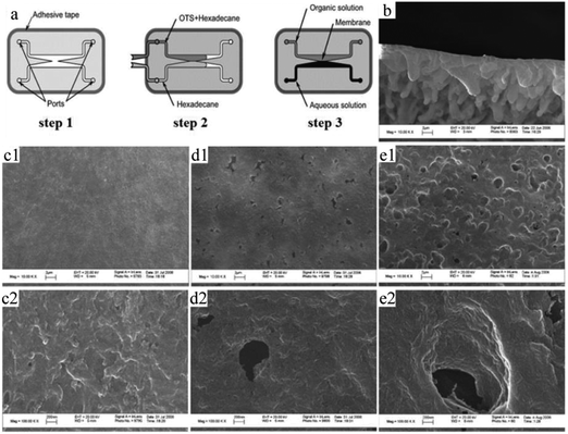 | ||
Fig. 31 (a) Illustration of interfacial membrane fabrication and SEM images of (b) a porous membrane formed by interfacial polymerization (angled view) and membranes obtained with (c1 and c2) 0, (d1 and d2) 10 and (e1 and e2) 20 mg PEG in a 60% 1,6-diaminohexane aqueous solution. The magnifications are 10![[thin space (1/6-em)]](https://www.rsc.org/images/entities/char_2009.gif) 000 (b, c1, d1 and e1) and 100 000 (b, c1, d1 and e1) and 100![[thin space (1/6-em)]](https://www.rsc.org/images/entities/char_2009.gif) 000 (c2, d2 and e2). Reproduced with permission from ref. 255. Copyright 2008 Wiley Periodicals, Inc. 000 (c2, d2 and e2). Reproduced with permission from ref. 255. Copyright 2008 Wiley Periodicals, Inc. | ||
Materials can also be decorated with a 3D porous “coat”, via photo-induced radical polymerization in a microfluidic device. Wang et al.172 fabricated a sensitive surface-enhanced Raman scattering (SERS) optrode from GMA, ETPTA and DMPA, densely decorated with silver nanoparticles, covering the tip of an optical fiber (Fig. 32). The porous layer thickness and the pore size increased with irradiation time, ranging from 4 to 149 μm and from 0.4 to 1.0 μm for 1 and 4 min polymerization time, respectively.
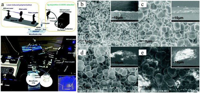 | ||
| Fig. 32 (a) SERS optrode-integrated microfluidic chip. SEM images of porous polymers covering the tip of optical fibers, prepared with UV-irradiation time (b) 1, (c) 2, (d) 3 and (e) 4 min. The insets are side views. Reproduced with permission from ref. 172. Copyright 2012 American Chemical Society. | ||
More recently, Liu et al.258 unprecedentedly reported a direct and versatile approach that combines a modified electrospinning setup based on a microfluidic nozzle with nonsolvent-induced phase separation to fabricate ultrafine fibers with interconnected macropores (Fig. 33). It exhibited higher specific surface area (48.66 ± 8.30 m2 g−1), larger pore size (116.73 nm) and pore volume (0.169 ± 0.007 cm3 g−1) in comparison to conventional electrospun porous fibers. In brief, two immiscible solvents, a polymer solution (20% polystyrene solutions with different THF/DMF ratios) and a mixing solvent (cyclohexane) were, respectively, pumped into the channel and well mixed before simultaneous electrospinning processes under selected operating conditions according to their previous studies.259,260 More importantly, various immiscible solvents/solutions can be electrospun by in situ mixing without solute precipitation. The oil adsorption results of macroporous fibers will be attractive to the investigation on and generation of heterogeneous fibers by in situ mixing electrospinning for potential applications.
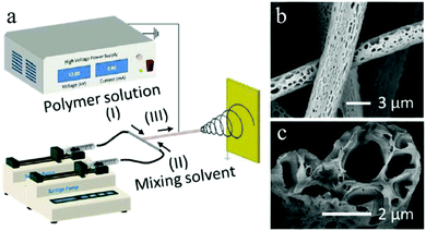 | ||
| Fig. 33 (a) Schematic illustration of an in situ mixing electrospinning process for macroporous fiber fabrication. SEM images of the (b) surface and (c) cross section of macroporous fibers. Reproduced with permission from ref. 258. Copyright 2016 American Chemical Society. | ||
4.2. Ordered macroporous particles
Chung et al.275 created porous scaffolds for tissue engineering via adjusting the flow rate of an alginate solution and the gas pressure to reach steady state monodisperse alginate droplets, which encapsulated nitrogen gas bubbles in a continuous mode generated in a microfluidic FFD. At a low liquid flow rate and high gas pressure, the microbubbles were less stable and more polydisperse. The microbubbles were closely packed in a container with a concentrated CaCl2 solution, where it gelated by vacuum degassing. The alginate scaffold exhibited a periodic interconnected porous structure (Fig. 34). Furthermore, the pore size could be adapted by varying the fluid velocity, gas pressure as well as the viscosity of the solutions. The pores were well-ordered near the surface, whereas deep inside the scaffold, the porous structure became less ordered and the size distribution of the pores became broader but still superior to scaffolds prepared by conventional methods. The feasibility of the microfluidic-generated scaffolds was further explored.28
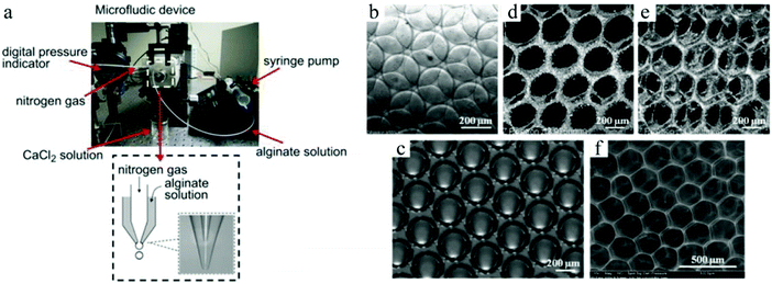 | ||
| Fig. 34 (a) Co-flow microfluidic device for alginate microbubble generation, (b) monodisperse microbubbles, (c) honeycomb structure after gelation, (d and e) confocal microscope images of 3D ordered scaffold after vacuum degassing and (f) SEM image of a sponge-type alginate scaffold. Reproduced with permission from ref. 28. Copyright 2011 Elsevier Ltd. | ||
More recently, Wang et al.276 designed a novel microfluidic FFD device for the formation of highly organized honeycomb-like scaffolds. In their setup (Fig. 35a), the liquid phase and gas phase were introduced in the upper and lower inlets in the opposite direction. Gas-in-liquid microbubbles were generated at the liquid–gas interface. The scaffold showed a hexagonal close-packed porous texture, which facilitated cell attachment and physiology.275,277,278
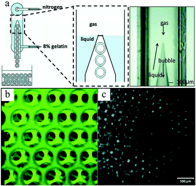 | ||
| Fig. 35 (a) Counter-flow microfluidic FFC device, (b) confocal microscopy showing the layer assembly of microbubbles and (c) highly organized structure. Reproduced with permission from ref. 276. Copyright 2009 Wiley Periodicals, Inc. | ||
In the FFD setup of van der Net t al.,279 2 different solutions A and B were pumped separately at identical flow rates in a parallel mode to create the continuous phase in the microchannels (Fig. 36a).
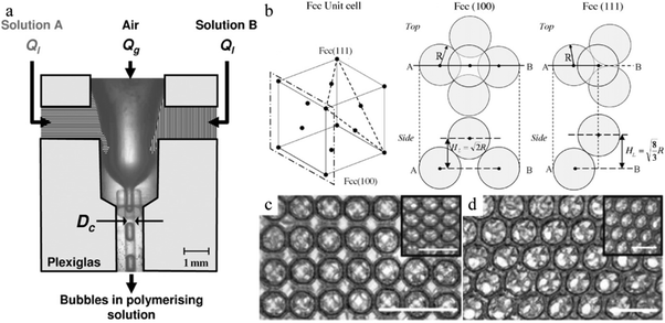 | ||
| Fig. 36 (a) Parallel microfluidic FFD device and (b) unit cell of the fcc structure. SEM images of 3 ordered foam layers of the (c) (100) direction and (d) (111) direction of fcc packing in the swollen state. Scale bar is 1 mm. The inset images are taken with the foam in the dried state (scale bar is 500 μm). Reproduced with permission from ref. 279. Copyright 2009 Elsevier B.V. | ||
The gas phase is sheared by the continuous phase and deformed to form monodisperse microbubbles. The polymerization did not start until solutions A and B met. Although the obtained hexagonal structures in the foam (Fig. 36b) were compactly arranged, their packing directions vary. One is the (100) direction of the face-centered-cubic (fcc) packing (square arrangement of bubbles at the surface, Fig. 36c), whereas the other one is the (111) direction of fcc packing (triangle arrangement of bubbles at the surface, Fig. 36d). After polymerization, the hexagonally structured foam could be dried and re-swollen reversibly. However, incomplete polymerization was observed in some cases, as some bubbles maintain the initial spherical morphology.
Colosi et al.280 also obtained ordered and interconnected porous 3D scaffolds using a FFD microfluidic foaming technique, based on the work of Chung et al.275 But, here the alginate solution and nitrogen gas were replaced by an aqueous poly(vinyl alcohol) (PVA) solution and argon gas. Immediately after generation, the monodisperse microbubbles were cross-linked with glutaraldehyde (GLU) and freeze-dried by liquid nitrogen to obtain an irreversible scaffold structure. These were compared to the ones formed by a traditional gas foaming technique. The scaffolds generated by the microfluidic foaming technique presented a superior porous structure compared to the ones made by traditional gas foaming, based on the pore size and wall thickness distribution and high-resolution computed micro-tomography (μCT) and SEM images (Fig. 37). However, the microfluidic scaffolds showed rather scarce pore interconnectivity, moderated pore volume and a limited production rate.
 | ||
| Fig. 37 μCT images of PVA scaffolds generated by (a) microfluidic foam and (b) traditional gas foam. SEM images of (c) microfluidic foam and (d) traditional gas foam. Reproduced with permission from ref. 280. Copyright 2012 American Chemical Society. | ||
3D scaffolds can also be prepared from HIPE monomers. However, polyHIPE scaffolds fabricated by conventional methods show rather poor reproducibility with uneven small pores, which may not satisfy the demand of tissue engineering. On the basis of Gokmen's study,19 Costantini and co-workers29 successfully prepared polyHIPE scaffolds from dextran-methacrylate (DEX-MA) using a microfluidic technique (Fig. 38a).281,282 In the first step, two immiscible phases added with DEX-MA or cyclohexane were introduced into a microfluidic FF chip to generate homogeneous O/W emulsions. In the second step, the O/W emulsions were cross-linked under UV-light (λ 365 nm) and then cured in an oven at 50 °C. In the third step, the product was placed in an organic polar solvent to extract the inner oil phase and create the macroporous structure. After washing with water and freeze-drying, the polyHIPEs presented a more interconnected and ordered architecture, compared to conventional HIPE templated scaffolds. By adjusting the flow rates of the 2 phases, distinct morphologies were obtained. The pore size of the scaffold increased upon using microchannels with larger dimensions (Fig. 38c–e). Three different lattice structures were present, including closed hexagonal packing together with [100] and [111] fcc packing (Fig. 38f–h). The concentration of the surfactant seemed to be vital to the final cellular structure. With higher surfactant concentrations, the closed porous structure evolved to a more open and interconnected one (Fig. 38i–k). However, the low production rate of the emulsions was still a limiting factor. To address this, parallelizing chips and junctions on a single chip were introduced.86,283,284
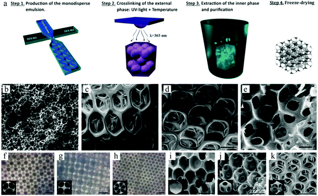 | ||
| Fig. 38 (a) Illustration of polyHIPE scaffold fabrication. SEM images of (b) conventional HIPE scaffolds and microfluidic HIPE scaffolds within (c) 1-fold, (d) 2-fold and (e) 5-fold volume of microfluidic FFD. Optical micrographs of microfluidic polyHIPEs with (f) hexagonal close packed, (g) fcc [100] and (h) fcc [111] crystal structures. SEM images of microfluidic HIPE scaffolds with (i) 1, (j) 7 and (k) 25% w/v Pluronic F68. Reproduced with permission from ref. 29. Copyright 2014 The Royal Society of Chemistry. | ||
Similar to 3D scaffolds, polymer foams are of particular interest for packing and insulation materials because of their low transport and thermal energy consumption. In 2016, Quell et al.285 used surfactant-stabilized HIPEs to fabricate two different kinds of highly ordered porous polymer foams, that is, closed-cell polyhedral foams (Fig. 39a) and open-cell spherical foams (Fig. 39c). For closed-cell polyhedral foams, monomers containing 1.28 mol% potassium persulfate (KPS) served as a dispersed phase. While for open-cell spherical foams, azobis(isobutyronitrile) (AIBN) replaced KPS with the same concentration and was added into the monomers. A mixture solution of styrene and divinylbenzene containing 10 wt% of the surfactant Hypermer 2296 was used as a continuous phase. Monodispersed emulsion templates were fabricated in the microfluidic chip, and then closely subsided in a continuous monomer matrix at a highly ordered level. Subsequently, emulsion templates were polymerized in an oil bath at 70 °C for 48 h. Eventually, the as-prepared polymer foams were purified by Soxhlet extraction with excess ethanol for 12 h before drying at room temperature. More importantly, they attributed different porous structures to the locus where the polymerization started. In the case of closed-cell polyhedral foams, initiation starts within the continuous monomer matrix and neighboring droplets are isolated by thin films. Otherwise, interconnected open-cell spherical foams were obtained.
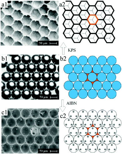 | ||
| Fig. 39 (left) SEM images and (right) schemes of (a) highly ordered closed-cell polyhedral foam, (b) monodispersed emulsion templates in a continuous monomer matrix in a highly ordered level, and (c) open-cell spherical foam. Reproduced with permission from ref. 285. Copyright 2016 American Chemical Society. | ||
![[thin space (1/6-em)]](https://www.rsc.org/images/entities/char_2009.gif) :
:![[thin space (1/6-em)]](https://www.rsc.org/images/entities/char_2009.gif) 1, creating a binary colloidal system. The aqueous suspension was sheared to homogeneous droplets by the continuous silicon oil phase in the microfluidic device.290 The droplets were collected in a container filled with silicon oil. The water was removed from the droplets by evaporation, which produced self-assembled polystyrene spheres with well ordered lattices, while the silica particles filled the void spaces between the spheres. After washing and calcination, the polystyrene spheres were removed resulting in the formation of uniform inverse-opal beads (Fig. 40).
1, creating a binary colloidal system. The aqueous suspension was sheared to homogeneous droplets by the continuous silicon oil phase in the microfluidic device.290 The droplets were collected in a container filled with silicon oil. The water was removed from the droplets by evaporation, which produced self-assembled polystyrene spheres with well ordered lattices, while the silica particles filled the void spaces between the spheres. After washing and calcination, the polystyrene spheres were removed resulting in the formation of uniform inverse-opal beads (Fig. 40).
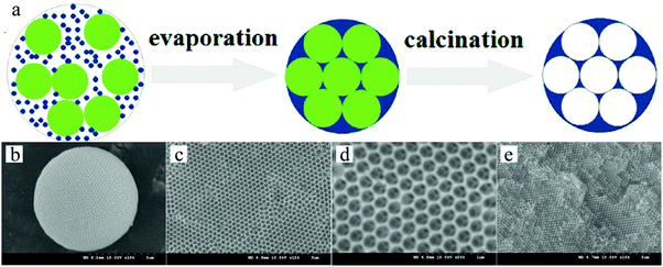 | ||
| Fig. 40 (a) Illustration of the generation of inverse-opal spheres. Reproduced with permission from ref. 288. Copyright 2014 American Chemical Society. SEM images of (b) whole inverse-opal spheres, (c) ordered porous surface and (d and e) ordered and interconnected internal cellular structure. Reproduced with permission from ref. 289. Copyright 2009 Wiley-VCH. | ||
Hexagonal close packed macropores were observed on the surface and in the interconnected internal structure. To obtain this morphology the volume fraction of polystyrene spheres to silica particles was important. More in particular, a volume ratio below 8 or above 10 gave a more disordered crystal structure and reduced the mechanical strength. A ratio of 9 led to greater surface area and more interaction sites, providing easier access for analyses to their recognition site. The inverse-opal photonic beads prepared by Zhao et al.291,292 were utilized for the label-free detection of biomolecules. This was demonstrated without applying time-consuming immune assay methods.
Zhao et al.293 also used silica colloidal crystal beads (SCCBs)290 as sacrificial templates and prepared macroporous hydrogel photonic spheres with a well-ordered inverse-opal structure. First, the SCCBs were fabricated in a home-made microfluidic device290 and then calcined to 800 °C for 3 h. The pre-gel solution (39% PEG, 1% initiator, 2% acrylic acid and 58% water) was filtered into the voids by capillary force. To ensure full void-filling, the SCCBs were pre-treated with piranha solution (30% H2O2 and 70% H2SO4) for 6 h, followed by washing and drying in nitrogen. The spheres got their opal architecture by polymerizing the pre-gel solution under UV-irradiation. After dissolving the template SCCBs in HF (1–2%), macroporous hydrogel photonic spheres were obtained. By increasing the PEG concentration, the mechanical strength was improved at the cost of structure order and a stable reflection peak position due to swelling. Fig. 41 shows the hexagonal close-packed SCCB surface and the well-ordered open porous and interconnected texture, before and after etching the templates. Conventional photonic band gap (PGB) crystals, which act selectively on photons like semiconductors do with electrons in electronic devices, can have opaline lattices which results in cooperative light scattering,294 often resulting in a very limited PBG and only a few narrow stop bands. Compared with conventional PGB crystals, macroporous hydrogel photonic spheres show angle-independent specific color with wider stop band gaps and are promising for advanced optical applications, such as reflection-based displays, barcodes and label-free sensors.
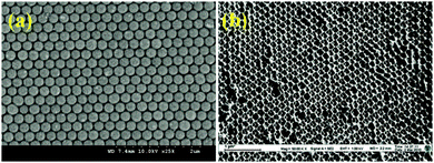 | ||
| Fig. 41 SEM images of a highly ordered surface of (a) template SCCB and (b) PEG inverse-opaline photonic sphere. Reproduced with permission from ref. 293. Copyright 2010 American Chemical Society. | ||
Wang et al.295 combined a microfluidic technique and a templating technique, which differed from the traditional top-down and bottom-up methods,288 to prepare multi-responsive poly(NIPAm-co-methacrylic acid (MAA)) photonic crystal microparticles (HPCMs) with an inverse-opal structure (Fig. 42). First, monodisperse emulsion droplets encapsulating silica nanoparticles with a diameter of around 220 nm were generated in a co-flow microfluidic device, followed by water evaporation. After washing with hexane to remove the oil phase and calcination, silica colloidal crystal microparticles (SCCMs) were obtained, which acted as templates for the formation of inverse-opal hydrogel microparticles. This was carried out in 3 steps: (1) immersion of the microparticles in a mixture of precursors and photo-initiators, (2) in situ UV-induced polymerization and (3) selective removal of templates by HF etching. Eventually, HPCMs with an inverse-opal structure were obtained. HPCMs bearing desired reactive functional groups (e.g. NIPAm as a temperature sensitive group and MAA as a pH sensitive group) showed rapid and sensitive responses to temperature and pH variations. Remarkably, the response rate was less than even 1 min. Other functional behaviors such as magnetic response could be introduced as well in HPCMs without affecting the temperature and pH responses too much.
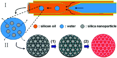 | ||
| Fig. 42 Inverse-opal HPCM fabrication by combining a microfluidic technique I and a templating technique II. Reproduced with permission from ref. 295. Copyright 2013 American Chemical Society. | ||
More recently, Ye et al.296 developed novel microcapsules (Fig. 43a) consisting of densely packed opal photonic crystal (PhC) cores and responsive inverse-opal PhC hydrogel shells using similar SCCB templates.293
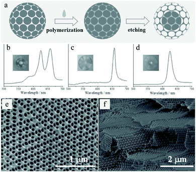 | ||
| Fig. 43 (a) Inverse-opaline hydrogel sphere formation. Reflection spectra and images (insets) of (b) the inverse-opal sphere, (c) SCCB and (d) PhC hydrogel beads. SEM images of highly ordered and interconnected porous structure of the (e) surface and (f) inner section. Reproduced with permission from ref. 296. Copyright 2014 Wiley-VCH. | ||
The microfluidically-generated SCCB templates had high monodispersity and brilliant structural colors due to the ordered arrangement of the spherical silica nanoparticles. After complete polymerization of the pre-gel solution, the hydrogel was disrupted by immersion in a buffer solution. Inverse-opal PhC hydrogel spheres were then fabricated by etching the SCCB templates inducing pore formation (±5 min). The etching conditions influenced the thickness of the inverse-opaline hydrogel shell, resulting in different relative refractive indices of the shell and core in the PhC microcapsule (Fig. 43b). Their reflection peaks differed only from those of SCCBs and PhC hydrogel spheres, exhibiting only one reflection peak (Fig. 43c and d, respectively). The PhC microcapsules displayed a highly ordered and interconnected macroporous structure (Fig. 43e and f), not only on the surface but also on the inside of the microcapsules, which is beneficial to diffusion imitated processes.
Inverse-opaline microsphere (IOM) crystals possess an isotropic band-gap property, differing from conventional 2D or 3D film-type colloidal ones,71,297,298 making them attractive for optical applications. Ionic liquids are salts consisting of organic anions and cations and are liquid below 100 °C. They have some advantages, such as negligible vapor pressure, incombustibility, reasonable chemical and thermal stability and high ionic conductivity.299 Poly-ionic liquid inverse-opaline microsphere (PIL-IOM) crystals showed unprecedented properties beyond those of their individual constituents. PIL-IOMs were fabricated by Cui et al.300 using a two-step procedure. Homogeneous silica nanoparticles were assembled into hexagonally packed crystalline lattices by droplet-based microfluidic synthesis,301,302 concomitantly with infiltration of imidazolium-based PIL monomers in the voids. The PIL-IOMs were isolated after UV-induced polymerization and removal of the silica nanoparticle templates with HF. The crystals exhibited brilliant color due to their uniformity in size and architecture (Fig. 44a). Further observation under SEM (Fig. 44b and c) illustrates the highly ordered interconnected macroporous structure, distributed over the whole particle surface. The relatively wide optical stop-band could be tuned from 400 to 700 nm by introducing different diameters of silica nanoparticles. PIL-IOMs could not only be used as stimuli-responsive photonic microgels, but also as multifunctional particles that mimic conventional molecules in terms of optical properties, molecular recognition, derivation and anisotropy.
 | ||
| Fig. 44 (a) Optical image of the ordered macroporous PIL-IOMs. SEM images of the (b) surface and (c) cross-section. Reproduced with permission from ref. 300. Copyright 2014 Wiley-VCH. | ||
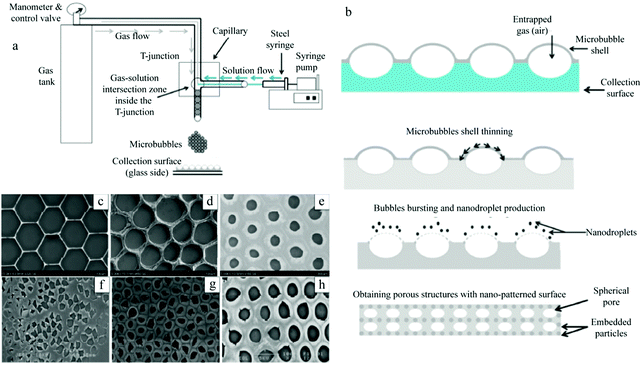 | ||
| Fig. 45 Schematic illustration of (a) monodispersed microbubble generation and (b) ordered porous film fabrication process. SEM images of the effect of the polymer concentration on the porous structure: (c) 0.1 wt%, (d) 0.3 wt%, and (e) 0.5 wt%. And SEM images of the effect of the surfactant (PEG-40S) concentration on the porous structure: (f) 0.25 wt%, (g) 0.5 wt%, and (h) 0.75 wt%. Reproduced with permission from ref. 304. Copyright 2016 American Chemical Society. | ||
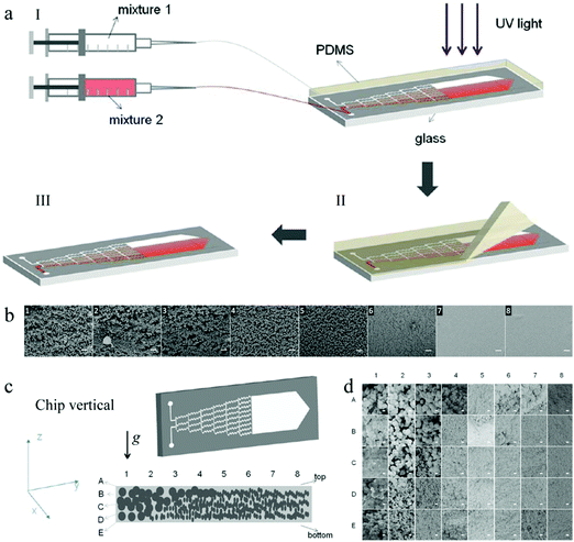 | ||
| Fig. 46 (a) Fabrication and (b) SEM images of a linear gradient porous film. (c) Fabrication and (d) SEM images of a wedge-like gradient porous film. Scale bars are 20 μm (b) and 1 μm (d). Reproduced with permission from ref. 318. Copyright 2013 American Chemical Society. | ||
4.3. Radially hierarchical porous particles
Nature brings the inspiration for many hierarchical structured materials, with pores spanning in the range of a few nm to mm.325–335 Sea sponges are typical examples. Such hierarchical porous structures stand in for their mechanical robustness and efficient biological exchange processes. In general, large size pores provide easier access with low resistance for the macromolecules, while small size pores can offer large functional surface area for molecular interaction with grafted functional groups. Especially in regenerative medicine applications, hierarchical structured materials with macropores (>300–400 μm) are indispensable to vascularise the implanted scaffold,336 while small pores with the dimension range of 50–100 nm are desired to promote cell migration, proliferation and differentiation to speed up tissue recovery.337 Thus, being able to control porosities in different size ranges allows us to steer the loading capacity and the mass transfer profile in cell cultures.Methods to design meso and macroporous materials include phase separation phenomena,338 removal of templates such as bubbles, particles and droplets339–345 and conventional emulsification and foaming techniques, often leading to broad pore size distributions.340,346 Additional physical or chemical gelation reactions are required to fix the structure because the templating bubbles, particles and droplets tend to coalescence and show Ostwald ripening.210,342,347 In 2009, Lee and Weitz27 reported the fabrication of hierarchical porous inorganic microparticles via simple evaporation of the middle solvent layer. Moreover, droplet condensation on the surface of polymer solutions is regarded as an elegant physical method to generate pores of a few micrometers.348 Despite all these, this method was limited to obtain 2D structures with little flexibility to tune the pore size according to different requirements. Choi et al.175 employed the W–W/W–O emulsion as a modified microfluidic device (Fig. 47a) to prepare radially hierarchical porous microbeads. The dimension and morphology of the droplets were affected by the setup.211,212 In a dripping mode double emulsions were obtained. To form the hierarchical porous structure, they used fast evaporation of the organic solvent and emulsion templating. In contrast, slow evaporation of the solvent leads to microbeads with a dense structure. Interestingly, the final porous beads presented 2 different types of pore surface (Fig. 47b). The development of the small pores could be attributed to fast solvent evaporation, while the large pores were formed upon introducing a homogenized W/O emulsion.
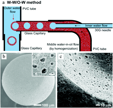 | ||
| Fig. 47 (a) Scheme of a microfluidic apparatus for double W–W/O–W emulsions. SEM images of a (b) radially hierarchical porous surface and (c) cross-sections of PLGA microbeads. The scale bar of the inset in (b) is 5μm. Reproduced with permission from ref. 175. Copyright 2009 Wiley-VCH. | ||
Later, practical fabrication of bimodal macro/mesopore structures was introduced by Zhai et al.,349 based on a temperature-induced gelation (rather than a polymerization reaction) integrated with a microfluidic coaxial microdevice. Methylcellulose (MC, showing reversible-thermosensitive behavior) and PEG (featured with auxiliary functional groups) were used for the synthesis of radially hierarchical porous microspheres with diameter around 490 μm. First, monodispersed droplets were generated and treated in water baths at 90 °C (Fig. 48a). After complete gelation, the solid spheres were washed with acetone, dried at 80 °C and calcined at 550 °C. The spheres produced from sample 1 (containing 0.50 g MC) and sample 2 (0.25 g MC) showed distinct morphologies (Fig. 48b–g). Sample 1 spheres showed a densely porous surface and homogeneous macroporous interior structure (around 1 μm), whereas sample 2 spheres presented dense pores on the surface but smaller more homogeneous macropores (around 0.1 μm) in the interior. Mesopores also widely existed in the spheres with pore sizes of 13.8 nm in sample 1 and 20.5 nm in sample 2, as determined by nitrogen adsorption–desorption measurements.
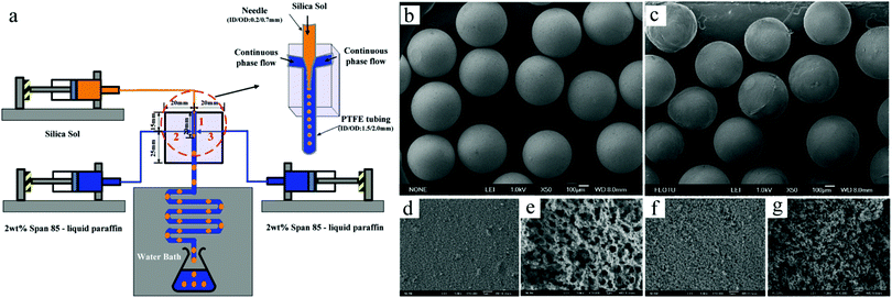 | ||
| Fig. 48 (a) Schematic diagrams of the coaxial device. SEM images of (b and c) spheres, (d and f) porous surface and (e and g) internal structures of sample 1 and sample 2, respectively. Reproduced with permission from ref. 349. Copyright 2010 American Chemical Society. | ||
In addition, Kim et al.350 introduced a simple one-step double emulsion strategy to prepare multi-cored microcapsules with a porous surface in a dual-continuous coaxial microfluidic apparatus (Fig. 49a). Silica particles (900 nm), pretreated with dichlorodimethylsilane (DCDMS), were added to the ETPTA solution to obtain a silica-ETPTA suspension (middle phase). The emulsion droplets were generated in the capillary device and then polymerized by UV-irradiation for 1 s. By precisely adjusting the flow rates of the 3 phases, the number of cores could also be manipulated (Fig. 49b). The diameter of the silica nanoparticles embedded in the thin ETPTA membrane was slightly greater than the membrane thickness, resulting in partial exposure of the particles on both core and outer sides (Fig. 49c). Ultimately, the wet etching process with 5% HF solution dissolved the embedded silica nanoparticles creating a well-defined porous surface.
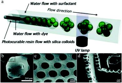 | ||
| Fig. 49 (a) Schematic illustration of multi-cored microcapsule fabrication. SEM images of a (b) microcapsule with 10 cores in gyro-elongated square dipyramid geometry and porous membrane, (c) surface and (d) cross-section. Reproduced with permission from ref. 350. Copyright 2011 Wiley-VCH. | ||
Uniform polymeric microparticles with controllable hierarchical interconnected porosity have also been reported using W/O/W emulsions351 (Fig. 50h). First, monodisperse W/O/W emulsions were generated in the glass-capillary microfluidic device. Herein, the partially water-soluble oil phase contained a surfactant (PGPR). Depending on the numbers of inner microdroplets (N, Fig. 50a), the inner structures were closely packed in distinct ways. Mass exchange between the inner and the outer aqueous phase occurred through the oil phase and was facilitated by the surfactant. The oil phase was partially miscible with the aqueous phases, resulting in the formation of fine aqueous nanodroplets (Fig. 50e and f). After UV-induced polymerization of the monodisperse W/O/W emulsions, hierarchical porous microparticles with well-defined micrometer- and nanometer-sized pores (Fig. 51a) left from the inner microdroplets and the mass transfer-induced aqueous nanodroplets, respectively (Fig. 50c, d and g). The combination of these two size-scaled highly interconnected pore structures was translated into advanced features, such as enhanced mass transfer, increased specific surface area and flexible morphology and functionality. The introduction of magnetic nanoparticles (Fig. 51b) showed synergy with the porous structure, useful for further application.
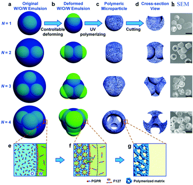 | ||
| Fig. 50 (a–g) Schematic illustration of the fabrication of microparticles with controllable interconnected hierarchical porosity using W/O/W emulsions and (h) corresponding SEM images (scale bar 200 μm). Reproduced with permission from ref. 351. Copyright 2015 American Chemical Society. | ||
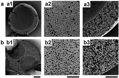 | ||
| Fig. 51 SEM images of the cross-section of hierarchical microparticles obtained from a W/O/W emulsion with (a1) non-magnetic and (b1) magnetic nanoparticles, with the corresponding magnifications (a2 and a3) and (b2 and b3). Scale bars are 50 μm in (a1 and b1) and 20 μm in the rest. Reproduced with permission from ref. 351. Copyright 2015 American Chemical Society. | ||
Carroll et al.352 designed a surfactant micelle nano-emulsion mixture and combined it with tinplating silica microparticles to fabricate hierarchical porous spheres. Niño-emulsion droplets evolved into large pores with a diameter of tens of nm, while self-assembled surfactant micelle structures resulted in a subset of small pores with a diameter of several nanometers.353 First, the silica precursor droplets were formed in the microfluidic device with 2 different geometries, T-junction and flow focusing (Fig. 52a), and collected in a reservoir. The remaining water and the silicate reaction by product ethanol were eliminated via evaporation-induced solidification. Then, the solids were immersed in water or toluene to form the interconnected pores followed by washing and drying. Eventually, hierarchical porous spheres with honeycomb-like surface were obtained (Fig. 52b and c). Carroll also demonstrated that these particles can be used as replica electrocatalyst materials354,355 and high-surface-area scaffolds.356,357
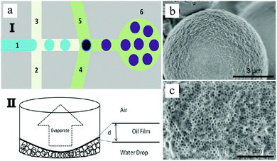 | ||
| Fig. 52 (a) Illustration of microfluidic-derived hierarchical porous spheres obtained with a micellar nano-emulsion and silica microparticles. SEM images of (b) tha honeycomb-like porous surface and (c) corresponding magnification. Reproduced with permission from ref. 352. Copyright 2013 American Chemical Society. | ||
More recently, Fan et al.358 provided a simple and robust in situ microfluidical fabrication of hierarchical porous poly(ε-caprolactone)/silica (PCL/SiO2) hybrid microspheres. The superiority of this new strategy for radially hierarchical porous architecture lies in a synergistic effect between the sol–gel process (hydrolysis and condensation of a silane precursor) and solvent extraction in droplets. More importantly, this process not only avoided the complicated post-treatment by using porogens/sacrificed templates, but also ensures the uniform distribution of silica in the PCL matrix. In brief, the uniform droplets were firstly generated in the microchannel, and then collected in a certain concentration of PVA aqueous solution. After being solidified at room temperature for 1 day, the microspheres were centrifuged and washed with excess deionized water before the final freeze-dry process. It is found that ammonia, used as a catalyst for silane hydrolysis, played a decisive role in the formation of hierarchical porous structures. At the same time, via adjusting ammonia concentration, the porous structures and the surface morphology can be easily controlled (Fig. 53).
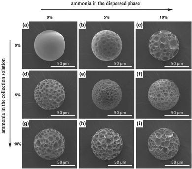 | ||
| Fig. 53 SEM images of PCL/SiO2 hybrid microspheres fabricated by adjusting the ammonia concentration in the continuous phase and/or collection solution. Reproduced with permission from ref. 358. Copyright 2016 American Chemical Society. | ||
Besides, Sommer et al.359 used monodisperse PCL particles obtained by microfluidics360 as sacrificed templates, combining with the 3D printing technique, to fabricate hierarchical silk porous materials with unprecedented structural control shown in Fig. 54. In detail, the microfluidically-synthesized PCL templates with different magnitudes in size were firstly added into silk fibroin-based ink to obtain the original materials by the 3D printing technique. Secondly, the removal of templates led to hierarchical porous silk-based materials. Finally, the PCL particles can be electrostatically coated with latex nanoparticles to build a porous architecture at three hierarchical levels. Due to moderate biodegradability of silk, the resulting structures turned from close to open porosity. Subsequently, these pore templating particles can be further modified with functional nanoparticles for various application fields from structural materials to thermal insulation. Meanwhile, Sommer and coworkers360 also introduced silk fibroin scaffolds with an inverse opal structure for tissue engineering application.
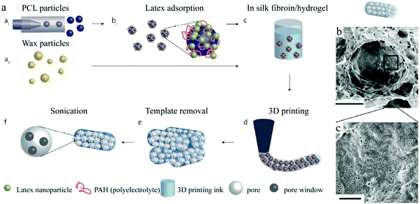 | ||
| Fig. 54 (a) Schematic illustration of the fabrication of 3D printed silk fibroin with a hierarchical porous structure. (b and c) SEM images of the resulting hierarchical porous silk fibroin structures. Reproduced with permission from ref. 359. Copyright 2016 American Chemical Society. | ||
4.4. Ordered hierarchical porous particles
Several research groups considered the inverse-opal architecture as a good scaffold for tissue engineering, mostly because the 3D structure is highly interconnected.361–364 But, most of the materials were neither biodegradable nor biocompatible, which limit their potential applications. Chitosan was applied as a biodegradable material by Choi et al.347 to fabricate inverse-opal scaffolds. Moreover, chitosan is not toxic, anti-microbial and biocompatible. Poly(ε-caprolactone) (PCL) microbeads with an average diameter of 147.7 μm were obtained in a simple microfluidic device (Fig. 55a) and then used as cubic close packed (ccp) lattice templates.210 Unlike the commonly used assembling methods for ccp lattices,362,363,365,366 here sedimentation–evaporation was employed to assemble the PCL microbeads into ccp lattices. A unique nanofibrous structure could be obtained during the freeze-drying of chitosan. Next to highly ordered macropores formed after the selective dissolution of PCL to remove the templates, randomly distributed smaller pores from a nanofibrous matrix were also present as a result of the phase separation (Fig. 55b–d). Other biocompatible materials such as gelatine, collagen and hyaluronic acid were also tested under similar conditions, but with smaller mechanical performance.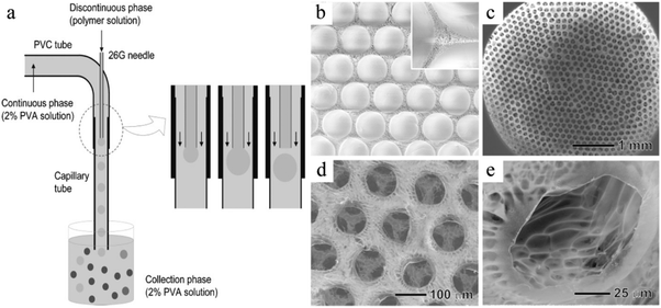 | ||
| Fig. 55 (a) Illustration of the generation of uniform PCL microbeads. Reproduced with permission from ref. 210. Copyright 2009 Wiley-VCH. SEM images of (b) the freeze-dried ccp lattice, (b) top view of the inverse opal scaffold, (c) magnified view of the top surface and (d) side wall in a macropore with several smaller pores. Reproduced with permission from ref. 347. Copyright 2009 Wiley-VCH. | ||
Studart et al.367 described a versatile and simple approach to fabricate customized porous materials with up to 3 hierarchical levels. Surprisingly, the principle relied solely on the process of drying complex suspensions containing droplets, colloidal particles and surface active molecules dispersed in the absence of any type of gelation. Monodisperse polystyrene particles (400 nm) were prepared by surfactant-free emulsion polymerization. Homogeneous oil droplets were obtained in a dripping mode212 in 2 kinds of glass microcapillary devices: co-flow and flow-focusing geometry. The flow rates of dispersed and continuous phases were constant in all experiments. The resulting oil droplets were stabilized by adsorbing either in situ hydrophobized colloidal droplets (silica or polystyrene) or surface active molecules at the oil–water interface (Fig. 56).
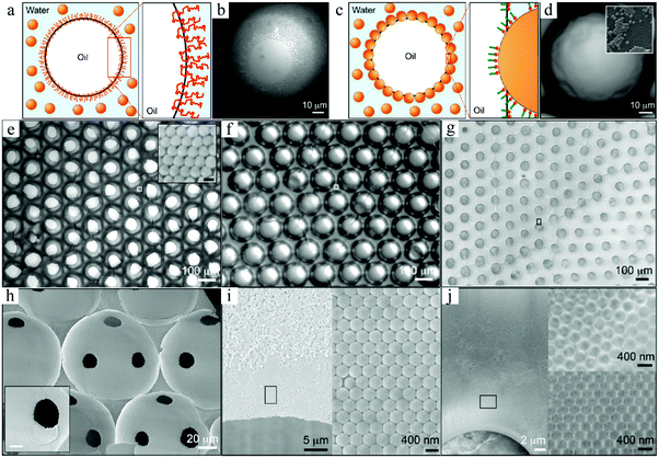 | ||
| Fig. 56 (a and c) Schematic diagrams and (b and d) top views of surfactant-stabilized and particle-stabilized droplets, respectively. Hierarchical porous structures from (e) PVA-, (f) silica- and (g) CTAB-stabilized droplets. (h) Magnification of (e) illustrating the interstices between the macropores. (i and j) Magnified FESEM images of the region close to a macropore indicated in (g). Scale bars in the insets of (e) and (h) are 100 nm and 10 μm, respectively. Reproduced with permission from ref. 367. Copyright 2010 American Chemical Society. | ||
The stabilized droplets were polymerized and deposited on a glass substrate, followed by self-assembly (buoyancy effect) to highly ordered hexagonal arrays in the case of surfactant-stabilized droplets, whereas particle-stabilized droplets were able to form both compact ordered and random disordered arrays. For the particle-stabilized droplets, a textured coating on the surface of particles was observed (Fig. 56d). In contrast, only a thin air–water layer was present on the surface of the surfactant-stabilized droplets (Fig. 56b). Remarkably, the surfactant-stabilized droplets lead to an open ordered cellular structure (Fig. 56e), whereas the particle-stabilized droplets resulted in fully closed ordered arrays (Fig. 56f). Additionally, the nanoparticles compactly packed in the voids between the large pores (inset of Fig. 56e) were removed in the subsequent steps, resulting in a secondary pore hierarchy. The dried structures (Fig. 56i) presented ordered secondary pores in the vicinity of the large primary pores while more disordered pores were observed more distantly. The pore wall thickness could be adjusted by tuning the TEOS concentration in the aqueous feed (Fig. 56j), while the initial droplet diameter determined the ultimate aperture. Moreover, the type of droplet stabilizer (surfactants or particles) had a great influence on the interconnectivity between macropores (Table 3).
| Morphology | Structure with closed ordered arrays | Structure with open ordered arrays | |
|---|---|---|---|
| Droplet type | Particle-stabilized | Surfactant-stabilized | |
| PVA-stabilized | CTAB-stabilized | ||
| Dispersed phase composition | Photosensitive oil mixture containing 1,6-hexanediol diacrylate + trimethylolpropane ethoxylate triacrylate (monomers), 2-hydroxy-2-methyl-L-phenyl-L-propanone (initiator) and toluene (diluent) | Octane | Octane |
| Continuous phase composition | Aqueous suspension containing CTAB and silica particles | Aqueous suspension containing PVA and silica particles | Aqueous suspension containing CTAB, polystyrene particles and TEOS |
| Average large pore size (μm) | ±140 | ±125 | ±140 |
| Average small pore size (nm) | ±110 | ±110 | ±400 |
4.5. Complex cavity structures
Besides spherical also non-spherical monodisperse morphologies can be created using double emulsion templates. Lee and Weitz27,79,205,243 demonstrated the synthesis of non-spherical colloidosomes with a multi-compartmentalized structure in a glass capillary microfluidic device, combining a co-flow and a flow-focusing geometry. Colloidosomes are hollow capsules whose shells consist of densely packed colloidal particles.368–371 These materials are attractive in encapsulation and delivery applications due to their outstanding functional properties such as permeability, biocompatibility and selectivity.343,372 Non-spherical particles were able to encapsulate multiple materials independently in different subdomains (compartments) without cross-contamination.128 Some could pack more densely than the spherical ones due to their geometry.373,374 W/O/W double emulsions encapsulated different sets of aqueous droplets by varying the flow rate of 3 phases in the microfluidic device (Fig. 57a). The silica nanospheres surrounded the inner aqueous droplets. Initially, during oil removal, the internal W/O interface maintained spherical morphologies while the geometry of the outer O/W interface evolved to non-spherical. After vacuum drying, non-spherical colloidosomes with various morphologies and multiple compartments were observed (Fig. 57b–g). The number of droplets determined the final morphology (Table 4). Some colloidosomes presented complex (asymmetric) structures, where the inner and outer shell surfaces consisted of different nanoparticles.375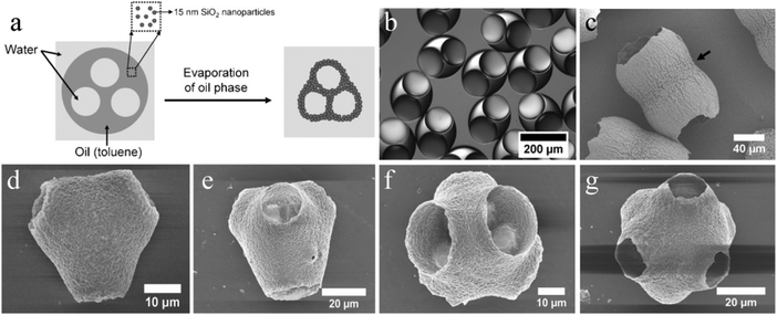 | ||
| Fig. 57 (a) W/O/W double emulsion template evolving to non-spherical colloidosome with multiple compartments. (b) Optical microscopy images of aqueous droplets encapsulated by W/O/W double emulsions. SEM images of colloidosomes with (c) 2, (d) 3, (e) 4, (f) 5 and (g) 6 compartments (N). Reproduced with permission from ref. 27. Copyright 2009 Wiley-VCH. | ||
| Phase composition | Internal W/O drop number (n) | Compartment number (N) | Particle morphology | ||
|---|---|---|---|---|---|
| Outer | Middle | Inner | |||
| 0.2–2 wt% PVA aqueous solution | Toluene suspension containing 7.5 wt% hydrophobic silica nanoparticles | 0–2 wt% PVA aqueous solution | 2 | 2 | Peanut-shaped |
| 3 | 3 | Three links | |||
| 4 | 4 | Triangular dipyramid | |||
| 5 | 5 | Square pyramid | |||
| 6 | 6 | Pentagonal dipyramid | |||
Later, Fang et al.376 described a simple one-step method for the dropwise formation of doughnut-shaped silica microparticles using a novel microfluidic FFD377 device with a serpentine channel (Fig. 58a), which improved the control over shape and size. Along the serpentine microchannel the deformation became more pronounced and the droplets gradually shrunk during solidification from 75 μm spheres to 25μm doughnut-shapes (Fig. 58b and c), as a result of the buckling instability at the interface. A thin membrane (2–3 μm) connected the 2 (asymmetric) cavities (Fig. 58d).378 According to the drying hydrodynamics, either pancake-shaped or torus-shaped silica microparticles could also be created by adjusting the experimental conditions, such as the silica content in the dispersed phase (TEOS + triethyl amine), the flow rates of dispersed and continuous phases,297etc.
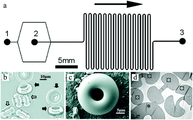 | ||
Fig. 58 (a) PDMS device with serpentine channel, (b) optical microscope tilted side view of doughnut-shaped silica particles, (c) SEM image of whole particles and (d) top (*) or side ( ) view TEM image of cross-section of particles. Reproduced with permission from ref. 376. Copyright 2011 American Chemical Society. ) view TEM image of cross-section of particles. Reproduced with permission from ref. 376. Copyright 2011 American Chemical Society. | ||
4.6. Customized macroporous particles (flow lithography)
All the particle synthesis methods described above are based on the precise control over the specific emulsion droplets inside microfluidic devices. The particle morphology in these methods is restricted to spheres or some deformed sphere shapes, such as hemispheres or rods. Photolithography offers a much easier route to yield such non-spherical particles, because the method employs versatile photomasks to define the shape. On the other hand, it has not been used often in the fabrication of particles due to the discontinuous nature of the process (low throughput). Besides, photoresistant materials are not ideal for applications that require biocompatible particles.In order to fabricate the non-spherical particles, novel microfluidic methods relying on photolithographic techniques were introduced recently.54,379 Arrays of mask-defined polymeric particles were formed under UV-light in the PDMS device in an automatized way. Fig. 59a shows a cross-section of the microfluidic device. Mask defined shapes were cross-linked in the centre of the device under a dynamic oxygen atmosphere, which was constantly diffusing through the PDMS wall and forming the inhibition layer above and beneath the particles. The thin oxide layer prevented clogging of particles allowing them to elute smoothly.380,381 One technique used a continuous flow of monomers passing through the microfluidic device producing arrays of arbitrary masked particles (continuous flow lithography, CFL). Another technique employed masks which were embedded inside the microfluidic device. Eventually, 4 types of flow lithography were developed (Table 5): CFL, stop flow lithography (SFL), stop flow interference lithography (SFIL) and lock and release lithography (LRL). An additional advantage over droplet-based methods is the possibility to fabricate particles with more than 3 different sections. Extending photolithography from photoresistant materials to other more bio-friendly materials could open the range of applications.
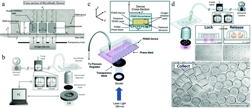 | ||
| Fig. 59 (a) Cross-section of a PDMS microfluidic flow lithography device. Reproduced with permission from ref. 380. Copyright 2008 American Chemical Society. (b) SFL device using a 3-way solenoid valve for rapid flow start and stop before and after polymerization. Reproduced with permission from ref. 379. Copyright 2007 The Royal Society of Chemistry. (c) SFIL. Reproduced with permission from ref. 382. Copyright 2007 Wiley-VCH. (d) LRL. Reproduced with permission from ref. 383. Copyright 2009 The Royal Society of Chemistry. | ||
| Technique (year) | Characteristics |
|---|---|
| CFL (2006) |
Automatized fabrication of non-spherical particles with 2D-extruded shapes down to 3 μm
Low Pe flows and pattern blurring Structures with poor resolution |
| SFL (2007) |
Automatized fabrication of heterogeneous biocompatible 2D-extruded particles
Improved resolution for more detailed structures (1–2 μm) Sharp interfaces between different sections of particles |
| SFIL (2007) |
Predictable internal 3D structures in one shot
High surface-area-to-volume ratio Controllable 3D porosity |
| LRL (2009) |
3D multifunctional particles with complex structures
Automatized fabrication of composite particles with multiple overlapping sections |
Most of the traditional approaches to make multifunctional encoded particles used for biomolecule analysis are complicated and time-consuming. Besides, they often generate only a limited number of particles. The processes for encoding, functionalizing or decoding active substrates (particles or surfaces) are expensive. Pregibon et al.384 presented a flexible and convenient CFL based approach, combining particle fabrication, encoding and probe incorporation into a single process. The obtained multifunctional particles possessed more than a million unique codes. The mix of 2 monomer flows (one loaded with an acrylate-modified probe and the other one with a fluorescent dye) constituted the laminar flow in a microfluidic channel and were then polymerized by UV-light (Fig. 60A). Particles with different regions were created in a single step: a graphically encoded region (fluorescent probe) and a probe-loaded region (modified probe). PEG, known as a bio-inert polymer, was used as the particle anchor point to “block” surfaces after the direct incorporation of the probes into the particles. PEG as a transparent material also allowed the fluorescent signal to pass through both sides of the particles. The resulting particles were extruded in 2D shapes (Fig. 60B–D) with macroporous “block” holes. Their chemical components were determined by the co-flowing monomer stream composition. Particles were designed to be “read” along 5 lanes along their length, with alignment indicators as the identification of the code position.
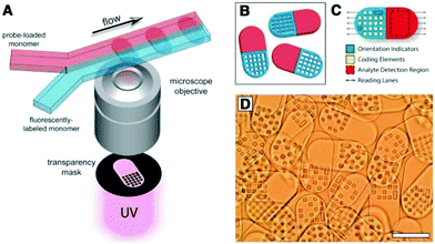 | ||
| Fig. 60 (A) Fabrication of dot-coded particles, (B) single-probe half-fluorescent particles, (C) particle subdomains for encoding and analyte detection and (D) differential interference contrast (DIC) image of particles (scale bar 100 μm). Reproduced with permission from ref. 384. Copyright 2007 Science. | ||
Later, Lee et al.165 studied the use of PEG as an effective porogen to create a macroporous hydrogel and a hydrogel slab within microfluidic channels. The inert PEG occupied the space within the polyacrylamide hydrogel without affecting the protein activity.385 In contrast to other common porogens, PEG is more hydrophilic and can be dissolved in water and therefore it was removed efficiently from the hydrogel.386 Pre-polymer solutions with 4% (w/v) polyacrylamide were exposed to 320–500 nm UV-light through a transparency mask, placed between the light source and microchannel. Upon addition of PEG porogens at concentrations higher than 5%, the polymerized hydrogel (Fig. 61a and b) became opaque and macroporous as a result of polymerization-induced phase separation. Higher loads of PEG porogens increased the porosity but decreased the structural strength. To increase the fabrication throughput, the flow rates of the different phases needed to be enhanced, but that leads almost inevitably to particle smearing and poor repeatability (unacceptable deformation) due to the limited UV-exposure time.379
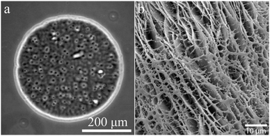 | ||
| Fig. 61 (a) Optical image of 5% PEG700DA (Mw 700 Da) macroporous hydrogel with 20% PEG10000 porogen and (b) SEM image of 5% PEG700DA macroporous hydrogel slab with 20% PEG35000 porogen. Reproduced with permission from ref. 165. Copyright 2010 American Chemical Society. | ||
4.6.2.1. Regular macroporous particles. Recently, Li et al.387 and coworkers synthesized highly macroporous particles via a microfluidic flow lithography approach with low-cost porogens (Fig. 62). The particles’ shapes depend on the designed photomask. Besides, a UV polymerization-induced phase-separation process results in a highly porous architecture with controllable pore size ranging from 100 nm to 500 nm. Moreover, they also systematically studied the pore-forming process with different operating parameters, such as the porogen type, porogen concentration and UV intensity.
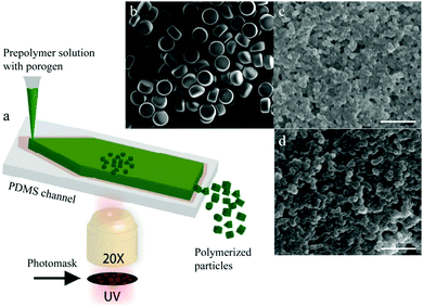 | ||
| Fig. 62 (a) Schematic illustration of SFL porous particle fabrication. SEM micrographs of (b) a certain number of polymerized porous particles, and (b) surface and (c) cross section of polymerized porous particles, respectively. Scale bars are 2 μm (b and c). Reproduced with permission from ref. 387. Copyright 2016 American Chemical Society. | ||
4.6.2.2. Irregular macroporous size square hole particles. The group of Doyle also demonstrated the advantages of SFL.379 The CFL and SFL methods were compared for the fabrication of a fixed number of particles using the same type of mask, UV-exposure time (0.05 s) and channel geometry (10 μm in height, 200 μm width and 1 cm length) (Fig. 63a–c). The insets show magnifications of the transparency masks employed. The difference between the inner and outer side dimensions of the concentric squares were 50, 20 and 10 μm, used for the preparation of particles with dimensions around 6, 2.5 and 1.25 μm, respectively (Fig. 63d, f and h). They showed well-defined morphology, the smaller particles however lacked sharp edges (Fig. 63h). The particles prepared using the CFL method are shown in Fig. 63e, g and i, having blurred edges and being less uniform than the ones obtained using the SFL method.
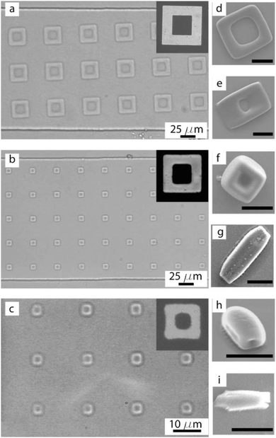 | ||
| Fig. 63 Concentric square masks, having differences between inner and outer sides of (a) 50, (b) 20 and (c) 10 μm, used for the SFL generation of macroporous square particles. (d, f and h) SEM images of SFL particles and (e, g and i) particles made with the same masks using CFL under the same conditions as SFL. The scale bars are 10 μm (d–i). Reproduced with permission from ref. 379. Copyright 2007 The Royal Society of Chemistry. | ||
4.6.2.3. Macroporous microgears. SFL was also reported as an effective tool for the generation of particles with more complex geometries, such as microgears, with uniform sizes ranging from 20 to 300 μm.388 Unlike simple geometries which could be obtained in short time, the complex microgears required much longer time to ensure complete polymerization to avoid their destruction during the ejection process. To enhance their structural integrity, the colloidal microgears were transformed to dense glassy silica ones by sintering for 3–10 h. After 10 h at 1150 °C, smooth transparent surfaces with dense internal structures were produced (Fig. 64a and b), while after only 1 h the microgears became translucent and even opaque, but their surface remained rough on the same size scale of the individual silica microsphere building blocks (Fig. 64c and d). Fully-open structures however have not yet been obtained, but might be created using other polymer types, like those used for photoresistant materials.
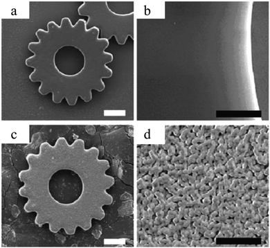 | ||
| Fig. 64 SEM images of (a) glassy silica microgear sintered at 1150 °C for 10 h, including (b) high magnification and (c) porous silica microgear sintered at 1150 °C for 1 h, including (d) high magnification. Reproduced with permission from ref. 388. Copyright 2008 Wiley-VCH. | ||
4.6.2.4. Bar-coded particles. Permeable PEG hydrogel particles consist of several spatially segregated regions, each hosting a graphical code in their unpolymerized macroporous holes. Some particles even carry various probe strips for multiplex target quantification. Particle-encoding holes can have different sizes representing 4 coding ‘bits’ (0, 1, 2, and 3). Besides, an extra bit (4) is used to provide the starting signal. These codes help to identify the antibody covalently attached on a separate probe region of the particle. The five bits could be arranged in 192 unique codes,381 if needed, similar to bar-coded chips.389 The task of the porous 3D gel matrix was to improve the kinetics of the recognition chain reaction of nucleic acids.390,391 The pore size could be modulated by varying the load of the cross-linking agent and porogen(s) in the precursor solution.
More complex particles with multidimensional anisotropy could also be fabricated with advanced microfluidic designs.383,392–394 However, they sometimes lacked technological solutions to rapidly decode particles and quantify target binding in a high-throughput manner, suitable for clinical research applications.395–397 To expand the application of bar-coded hydrogel particles, Doyle and his group developed a versatile microfluidic flow scanner, which decoded the particles in an accurate way and up to 25 targets per s, with multiplex detection encoded. The device consisted of 4 major parts: (1) creation of bar-coded microparticles, (2) protein target labelling, (3) scanning and analyzing the particles and (4) automated target identification. The bar-coded hydrogel particles were produced using a well-designed SFL device (Fig. 65c) described by Dendukuri et al.,379 a flow control equipment used by Bong et al.398 and a scan system built on the microscope that was used for particle generation.399,400 Stop-flow cycles were adjusted by the pressure and synchronized with UV-light pulses to simultaneously synthesize, encode and functionalize. By high-resolution design of the particle layout, hosting different adjacent chemical functionalities, reliable code readouts could be achieved (Fig. 65a). Earlier, scans occurred on equally spaced probes,401 whereas Boyle used a 30 μm width blank region inserted in the particle to separate the code and the probe. Another blank region was incorporated at the end of the particle to ensure symmetrical exposure of the probe to the carrier (Fig. 65b). Other studies also explored bar-coded microparticles for protein detection and other applications.399,402–406
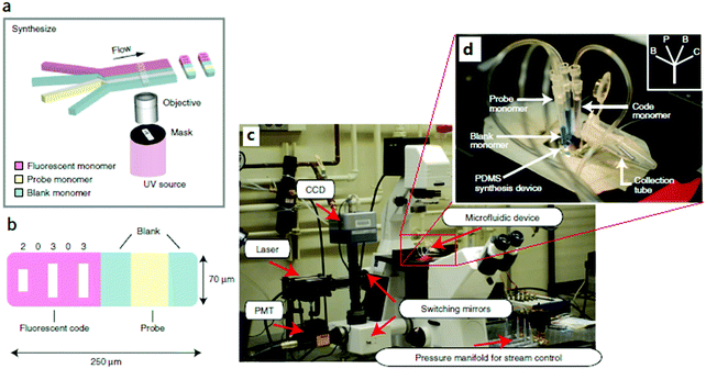 | ||
| Fig. 65 (a) Illustration of the fabrication of single-probed particles. (b) A bar-coded particle with code 20303, (c) microscope setup for synthesis and scanning: laser and PMT for scanning, UV for polymerization and CCD for synthesis and alignment and (d) blue colored feed to identify and adjust the monomer flow widths easily during the fabrication process: B: blank, P: probe and C: code. Reproduced with permission from ref. 381. Copyright 2011 Nature America. | ||
4.6.2.5. High AR functional layered sheets. The aspect ratio (AR, the ratio of the channel width to height) of microchannels is a critical parameter of PDMS chips. ARs below 20 resulted in weak mechanical strength.407 Channels with too high ARs resulted in sagging and limited sheet formation. By utilizing a glass support in stop-flow lithography, the generation of functional layered sheet structures with high ARs was realized in one step.408 Li et al.409 introduced slit-channel lithographs to prepare single- and even multiple-layer hydrogel sheets with controllable pore shapes and surface morphologies, designed for utilization in tissue engineering. The UV-shutter and the solenoid valve were precisely synchronized using a digital controller (Fig. 66a), which is important for the special morphologies of the sheets. In the single-layer sheet synthesis, a Pacman-arena styled sheet (Fig. 66b) with a pore gradient pattern ranging from 5 to 300 μm (Fig. 66c) was obtained, which can be used in multi-component filtrations.410 The pore shape was also altered by adjusting the location of the UV-focal plane along the microchannel. When setting the focal plane in the middle of the channel, the light beam reached the photomask in a straight angle resulting in sheets with uniform cylindrical pores (Fig. 66d). When lowering the focal plane location, the sheet showed conical pores caused by the inclination of the light beam (Fig. 66e and f). Both types of sheets were used in cell culture and biochemical analysis.411–415 Multi-layered sheet structures were obtained by introducing an external magnetic field. Fig. 66h shows 3 magnetic hydrogel sheets self-assembled into a 3D hydrogel structure with 60 μm square pores, good for nutrition supply and waste removal in large tissue growth. Compared to other techniques such as scanning beam lithography,416,417 photolithography418,419 and soft/hard mold lithography,407,420 the slit-channel lithography technique simplified the fabrication process considerably.
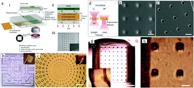 | ||
| Fig. 66 (a) Illustration of hydrogel sheet production, (b) Pacman-arena styled sheet, (c) gradient pore pattern and (d) cylindrical and conical pore formation. SEM images of the (e) cylindrical and (f) conical pores in the sheets and (g) multi-layered magnetic hydrogel sheets with square macropores and (h) corresponding magnification. Scale bars are 1 mm (b, c and g), 40 μm (e and f) and 100 μm (h). Reproduced with permission from ref. 409. Copyright 2014 American Chemical Society. | ||
 | ||
| Fig. 67 SEM images of PEGDA structures with different morphologies and volume fractions, fabricated with the same phase mask and (a) 700 ms exposure time with 1.2 wt% hydroquinone (inhibitor), (b) 1000 ms exposure time and 0.3 wt% hydroquinone and (c) special flower shapes fabricated from ethanol suspension and 300 ms exposure time. Reproduced with permission from ref. 382. Copyright 2007 Wiley-VCH. | ||
Fig. 67a and b show the cross-sectional views of the 3D structures obtained at a short exposure time/high inhibitor load and long exposure time/low inhibitor load, respectively. The latter 3D structures contained smaller pores and had a higher volume fraction. Upon shrinking in ethanol, flower-shaped structures were formed (Fig. 67c).
The release time was also important. Particles could be released at a critical pressure as a function of the device deformation. While the low pressure was maintained, the monomer exchange continued and addition of new chemical groups was possible before the release was started. This way, composite particles with multiple chemical regions and complex porous structures were obtained (Fig. 68a). First, the multi-inlet was filled with one type of monomer and precisely locked. Subsequently, by tuning the pressures of the inlet streams (but keeping them below 10 psi), locked structures with chemistry 1 were covalently linked to chemistry 2 through mask overlapping, then polymerized under UV-light and released by high pressure (Fig. 68b–f). The mask was compatible with different chemistries to selectively polymerize through overlapping, resulting in different particle types. Fig. 68g shows a particle obtained by applying 3 chemistries. The lag times were critical, as they determined the fluidic exchange and mask alignment. However, the production throughput decreases when multiple chemistries are employed.
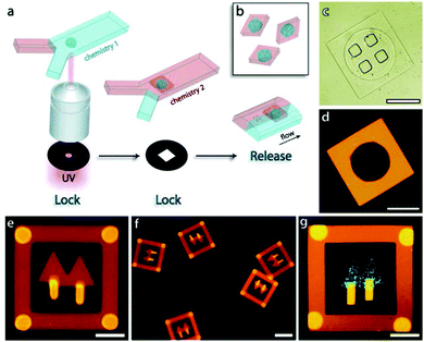 | ||
| Fig. 68 Composite particle (a) synthesis, (b) structure, (c) DIC image and (d) fluorescence microscopy image. Fluorescence microscopy images of (e and f) composite particles with an “autumn tree” pattern, with 6 thicker locks appearing as brighter regions and (g) composite particle with a “spring tree” pattern. Scale bars are 100 μm (c, d and f) and 50 μm (e and g). Reproduced with permission from ref. 383. Copyright 2009 The Royal Society of Chemistry. | ||
5. Applications
5.1. Catalytic applications
The development of different porous materials has opened great opportunities for catalytic applications, mainly as supports for catalysts and as nanoreactors (Fig. 69). They can provide efficient mass and heat transfer and host abundant catalytic active sites. Graphite, a nanostructured porous material, has intriguing structural features with a hexagonal close-packed opened porous structure. Natural and artificial zeolites, with pore sizes less than 1 nm, are widely used as catalytic nanoreactors.421,422 Here, macromolecules cannot enter and leave the confined space. Metal–organic frameworks (MOFs) exhibit similar structures with sub-nanometer-sized pores.423 Moreover, MOFs can act both as catalyst supports and as active sites. In general, catalytic active sites are loaded by covalent grafting, heteroatom doping or nanoparticle deposition. Larger-pore-sized mesoporous materials have also been developed.424,425 Among these materials, MCM-41 and SBA-15 are widely used in various catalytic reactions.426 Compared with microporous structures, mesoporous ones provide larger pore volumes, which benefits the mass transfer. Unfortunately, the increase of porosity can result in less stable cellular structures427,428 and further restrict their performance over time. Carbon nanotubes with pore sizes ranging from 1 to 100 nm429–435 and macroporous materials have also been employed for catalytic reactions.22,436–439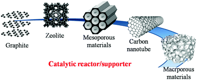 | ||
| Fig. 69 Common porous materials used as catalytic supports with increasing pore sizes and nanoreactors with gradually increased reaction spaces. | ||
Materials with hierarchical porous structures on the nano- and micrometer scales have also been explored to improve conventional micro-/meso-/macroporous materials as catalytic supports and nanoreactors.440–442 For this reason, the development of microfluidic techniques can play an important role in catalytic applications. Wacker et al.166 created magnetic macroporous spheres in a microfluidic device using silica particles and iron oxide nanoparticles and then functionalized them with horseradish peroxidase (HRP), frequently used as a signal amplifier in immune assays.443 This way the HRP functionalized particles could be recovered easily.444,445 Carroll et al.352 designed surfactant micelle/oil nanoemulsions and combined them with silica microtemplates to fabricate hierarchical porous spheres to improve the mass selective transfer in catalysis, but also for electrocatalysis materials.354,355 More recently, Kim et al.72 also demonstrated that the porous microparticles can be used as catalyst supports thanks to their intrinsic structural features. However, although microfluidically-generated porous materials possess so many distinct advantages, for future catalytic application, more efforts should be devoted to control their structures and morphologies. With the rapid progress of microfluidics in porous material fabrication, macroporous materials with higher specific surface area, larger pore size and pore volume, as well as better multi-functionalization superior to the current porous materials obtained by a conventional approach will certainly face a bright future in modern catalytic research and applications.
5.2. Optical applications
In recent years suspension-mediated arrays were exploited.446 Compared with the conventional microarrays on a plate,447,448 they offer greater flexibility. In particular, self-assembled periodic arrays of colloidal photonic crystals (CPCs), containing photonic band gaps (PBGs) which diffract light in long-wave-ranges, are attractive for application in advanced optical fields such as photonic crystal devices for light manipulation.449–452 Due to the periodic modulation of the refractive index between the building nanoparticles and the surrounding medium, PBGs allow only certain light wavelengths to be refracted.288 CPCs can synchronize optical signals by stop band positions originating from the periodic lattice spacing.295,296 Conventional microcarriers such as fluorescent dyes or quantum dots,292,384,453–460 which contain physicochemical carriers as the main spectrum-encoding elements, can show some defects: photobleaching during storage, fluorescent interference between encoding and analyte detection and biotoxicity of the quantum dots.289,291,293 CPCs, as an optical spectrum-encoding carrier, show characteristic reflection peaks originating from the stop-band. They result in a stable and sensitive detection.289,461 CPCs convert small physicochemical response signals to a well-defined optical change (stop band positions or structural colors).291,462–464 CPCs were developed for sensing various external stimuli, such as temperature,465–469 solvent,470–473 humidity,282,474–476 mechanical stress,477,478 pH,479,480 ions,481–483 light484,485 and electric/magnetic field.486–491To date, only a few conventional approaches exist for the controlled creation of crystals from colloids. Crystal structures formed from colloids in a state of suspense often show fragile behavior. The most predominant approaches for this task are:156 (1) flow- or evaporation-induced colloidal packing492–495 and (2) non-close packing induced by electrostatic energy, followed by immobilization.496,497 CPCs with various morphologies, such as thin film or bulk, were fabricated. The Bragg diffraction that occurs upon irradiation of CPCs generates different structural colors when observed from different angles, useful in the construction of some optical materials and devices that require wider viewing angles.288 Other drawbacks such as a relatively slow response rate for certain stimuli and the lack of high throughput assays limit their application.498
Photonic crystal beads (PCBs) were created to address these drawbacks.297,498,499 Thanks to their structural symmetry, these spherical CPCs were rotation independent when their surface was irradiated at a fixed incident angle of the light beam.289,500,501 Crystallization to PCBs was induced by evaporation and polymerization of suspensions with droplet template colloidal nanoparticles.288 To increase the refractive index, the nanoparticles need to be removed selectively to generate inverse-opal structures with broader PBGs and reduced attenuation length. Characteristic to inverse-opaline PCBs, long-range ordering of pores was crucial to the optical performance, resulting in stable specific reflection peak positions.286,291 Under normal light incidence, the reflection (stop-band) wavelength λ of PCBs can be estimated using Bragg's equation:289,296,502
| λ = 1.633 × d × naverage |
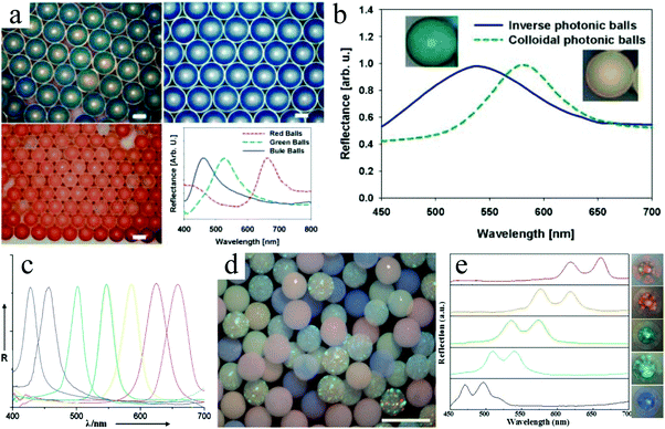 | ||
| Fig. 70 (a) Reflectance spectra and optical images of red, blue, and green PCBs composed of 190, 152, and 145 nm silica particles. (b) Normalized reflectance spectra and optical images of photonic balls before and after removing the 165 nm silica particles. Reproduced with permission from ref. 156. Copyright 2008 Wiley-VCH. (c) Reflection spectra and (d) 3D image (in water) of 7 inverse-opaline PCBs prepared with polystyrene spheres as sacrificial templates having, from left to right, 200, 215, 238, 262, 280, 298, and 315 nm sizes. Reproduced with permission from ref. 289. Copyright 2009 Wiley-VCH. (e) Reflection spectra of 5 kinds of inverse-opaline PCBs made with silica nanoparticles of, from top to down, 290, 260, 240, 220 and 200 nm sizes. Scale bars are 100 μm (a), 500 μm (d) and 200 μm (e). Reproduced with permission from ref. 296. Copyright 2014 Wiley-VCH. | ||
 | ||
| Fig. 71 (a) Optical response and optical images (insets) of PIL-IOMs upon exposure to aqueous solution with 6 different counter ions. Reproduced with permission from ref. 300. Copyright 2014 Wiley-VCH. (b) Illustration of the microparticle structure and the payload release upon irradiation with a NIR laser and (c) normalized volume change of microparticles with (black squares) or without (red dots) gold nanorods according to a cycle laser. Reproduced with permission from ref. 170. Copyright 2014 American Chemical Society. | ||
 | ||
| Fig. 72 (a) Reflection spectra and bright field microscopic images of 3 types of MIPBs. The cyan, green and red MIPBs were imprinted bovine haptoglobin (Hb), HRP and serum albumin (BSA), respectively. The dashed and solid lines are spectra of the MIPBs before and after multiplex detection. Reproduced with permission from ref. 291. Copyright 2009 Wiley-VCH. (b) Flow-through microfluidic device used to read reflection spectra of inverse-opaline PCBs. Reproduced with permission from ref. 289. Copyright 2009 Wiley-VCH. (c) Illustration of PCBs for label-free multiplex detection. Reproduced with permission from ref. 296. Copyright 2014 Wiley-VCH. | ||
Zhao and co-workers289 also developed a simple microfluidic device for in situ detection (Fig. 72b). When the PCBs passed the detection region, their reflection peaks could be detected using a microscope. More recently, by employing well-controlled wet etching processes, Ye et al.296 fabricated novel PCBs with close-packed opal cores as their encoding units offering stable diffraction peaks and responsive inverse-opal hydrogel shells. The latter acted as the sensing unit for target recognition, based on the shrinking behavior of the shells. These microparticles showed 2 reflection peaks, whose shifts could be used for the estimation of the target concentration (Fig. 72c).
Currently, the fabrication process of hierarchical porous particles with inverse opal structures is still complicated and apt to have deviation, which further affects their optical applications. One-step microfluidically hierarchical porous particle fabrication has a long way to go.
5.3. Drug release and delivery
Microfluidic methods represent a useful platform for therapeutic agent delivery,518 as microgels can be fabricated with precise control over particle dimension and its distribution. Over the past few decades, much effort has been devoted to develop μm or nm sized materials for drug-delivery systems (DDSs).519–523 DDSs aim to deliver the therapeutics in a spatio-temporal controlled manner: loading either hydrophilic or hydrophobic drugs in the desired dose, releasing them at the desired sites and minimizing side effects.524 Toxic effects can be attributed to premature drug release. Therefore, advanced functional DDSs with remarkable biocompatibility, biodegradability, stability as well as high drug-loading capacity are highly desired. Porous particles have demonstrated their benefits over solid ones as a result of their larger specific surface area for encapsulation and release of substances.525–531 Further design of their internal structure to create multicompartments made the encapsulation of multiple incompatible components possible, without cross-contamination.532 The addition of holes on the particle surface allowed the differently sized molecules to migrate through the thin wall in a selective way.533 DDSs could overcome adverse biopharmaceutical properties of the drugs and improved their bioavailability.519,522,523Recently, porous silicon (PSi) materials were developed as versatile carriers for drug delivery.523,525,534–538 The degradation rate of PSi materials to non-toxic silicic acid in vivo could be controlled by adjusting their porosity and surface chemistry.531,539–541 Furthermore, a wide variety of therapeutic and imaging agents have been successfully incorporated into PSi particles. However, the existence of free accessible pores imposed the risk of release of drugs from the particles during their transport.356,541,542 The pores could be sealed by using a matrix to ensure continuous release of the payloads for a prolonged time. In the future, customized ordered and/or hierarchical macroporous particles with regular or irregular shape can be easily obtained by advanced microfluidic technology according to the special requirements. It will accelerate the developments of microfluidically-synthesized macroporous particles in the wider biomedical field.
5.4. Tissue engineering
Tissue engineering was first introduced in the early 1990s543 to address the shortcomings of traditional tissue repair and transplantation, as an interdisciplinary approach between biology, materials science, medicine, and engineering. It aims at the successful transplantation of a bio-factor, such as cells, genes and proteins, within porous degradable materials, known as scaffolds.267,544–546 The use of 3D scaffolds in tissue engineering entailed precise control over the pore size and the interconnects between them, because these in turn determined the void space available for cell seeding.547,548 The interconnected pores provided proper exchange of nutrients and metabolic waste, and acted as a protective barrier for the cells to the immune system.175 The mechanical properties were also critical. Macroporous materials with interconnected morphology were suitable for tissue engineering.273,549–552 PolyHIPEs, a class of porous and permeable materials, were customized to serve as scaffolds.273 Various macroporous polyHIPE porous materials, based on both synthetic as well as natural polymers, were studied for their application in tissue engineering,553–559 whereas conventional polyHIPEs based on the action of shearing showed important shortcomings. First, the dimension of pores in these materials is below 100 μm, which is too small for cells to colonize, especially because the seeded cells often proliferated only at the outer surface rather than penetrating inside the materials.560 Secondly, both pores and interconnects were typically highly polydisperse resulting in lower performance of the material. Cells grown within such scaffolds may lead to undesired phenotypic diversity and inhomogeneous distribution. In contrast, computer-aided microfabrication techniques such as photolithographic patterning and layering, and direct writing and two-photon stereo-lithography, may provide the materials with the desired pore size and 3D interconnectivity, but these approaches are usually costly.268,269,561 Recently, a microfluidic technique was incorporated into the HIPE technique to overcome the morphological limitations of the conventional approaches.19 The microfluidic technique generated sets of droplets with equal dimensions in a highly ordered manner without any specific chemical process. This way, both hydrophilic and hydrophobic 3D porous scaffolds could be fabricated for tissue engineering applications. The study and application of microfluidically-synthesized macroporous particles as 3D porous scaffolds for tissue engineering are still insufficient. But, with the fast improvement of microfluidic-based fabrication, we believe microfluidically-synthesized macroporous particles will usher a better future in tissue engineering.5.5. Water treatment
Common wastewater treatments of streams from improper operation or accidental leakage during production, storage, transportation and usage of chemical products harmful to the environment are often based on chemical, physical and/or biological methods.562–564 However, operations such as emulsification, solidification and photocatalytic degradation require special conditions and can generate toxic by-products.565 Bioremediation methods may cause unnecessary secondary pollution from residual nutrients and microbial pollution.566 Most of the treatments of oil contaminated wastewater are merely physical methods. Adsorption is more suitable for rather small amounts of organic pollutants. Adsorption not only removes the pollutants, but also makes the recycling of materials possible. The most common adsorbing materials include polymers, carbon materials, natural minerals and biomaterials.567–570 The ideal oil–water separation adsorption materials should be: (1) enriched with alkyl groups, which selectively adsorb and efficiently separate the oily substances from the water and form strong molecular inter-atomic forces, (2) present a rich porous structure, high specific surface area and pore volume contributing to a high uptake capacity and (3) have excellent recyclability.571,572Removal of organic pollutants from surface or sub-surface aquifer water to reduce the ecological damage in the environment is a difficult task. The innovation of materials, especially porous particles, plays an important role in this area.563,573,574 To date, silica aerogels and activated carbons have been among the most common materials used for this task. However, with time these particles become unstable in such aqueous environments due to their inherent hydrophobic surface nature and eventually they need to be replaced.575–577 To achieve good water dispersion of hydrophobic particles, their surface morphology characteristics should be changed. Particles can absorb organic contaminants and remain well dispersed in aqueous environments by constructing a porous hydrophobic absorbing core and a hydrophilic surface. By combining mixing-induced phase separation and precipitation polymerization in a microfluidic device, particles with a hydrophobic porous core and a hydrophilic porous surface were designed to ensure excellent dispersion of particles in the aqueous phase with good adsorption capacity578 (Fig. 73a). Multilayered porous particles were obtained after removal of the porogen, assisted with a color change from dark to light (Fig. 73b), ultimately becoming transparent. The particles were effective for the uptake of organic oil directly from oil drops as for the uptake of organic molecules dissolved in an aqueous solution. The recyclability of these particles was also demonstrated.
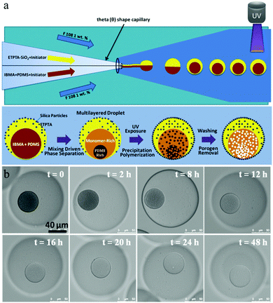 | ||
| Fig. 73 (a) Schematic illustration of the porous particle fabrication. (b) The optical images describing the process absorption of oil by particles and consequent increase of inner layer brightness during 48 h time period. Reproduced with permission from ref. 578. Copyright 2013 Wiley-VCH. | ||
In addition to porous materials with only one pore dimension, recently Zhang et al.351 introduced highly interconnected hierarchical porous microparticles for the adsorption of oil droplets in water. Magnetic Fe3O4 nanoparticles (diameter 12 nm) were prepared and then dispersed by ultrasonic treatment in the middle phase to generate the magnetic hierarchical porous poly(MMA-co-EGDMA) microparticles. Similar to their previous work,533 first EGDMA dyed with red color was added into water (Fig. 74a) and then dispersed into microdroplets by shaking (Fig. 74b), serving as an oil contaminated sample. For the removal of the oil, the poly(MMA-co-EGDMA) porous microparticles were added and adequately mixed (Fig. 74c). Remarkably, the dyed oil droplets could be separated from the microparticles by directed guiding with a magnet (Fig. 74d). The microparticles were recovered by washing the absorbed oil with ethanol and recycled up to 20 times without structural deformation (Fig. 74e). The results were compared with those obtained with poly(MMA-co-EGDMA-co-GMA) to study the effect of nanopores and different hierarchical porous structures (Table 6).
 | ||
| Fig. 74 Magnetic hierarchical porous poly(MMA-co-EGDMA) microparticles for magnetic-guided removal of dyed EGDMA microdroplets from water. Reproduced with permission from ref. 351. Copyright 2015 American Chemical Society. | ||
| Structure type | Average pore size (μm) | Porosity (%) | Oil adsorption capacity (μL) |
|---|---|---|---|
| 1 pore type (μm) | ±120 | 44 | <10 |
| 1 pore type (nm) | ±0.58 | 48 | ±20 |
| 2 pore types (μm) | — | — | ±30 |
| 3 pore types (μm) | — | — | ±40 |
The ever-increasing requirement for wastewater treatment and reuse gradually pushes conventional porous adsorbents to their limits. The solutions to the existing and future water challenges will depend on advanced adsorbents with unprecedented performances, such as higher specific surface area, distinguished hierarchical porous morphology, outstanding selective adsorption capacity, as well as less toxicity and acceptable mechanical properties. However, the current shortcomings of the microfluidic technique, for example, low yield and high cost, become another obstacle in the application of microfluidically-synthesized porous materials in water purification. Design and use of microfluidically-synthesized porous materials to solve these challenges become some of the most urgent problems in the future.
5.6. Bio-separation
In the field of biology, to study the interactions such as those between antibodies and antigens, or between receptors and cells, a series of sequential post-processing, such as separation, washing and purification, is required. The development of bio-magnetic porous particles has been shown to be successful in this research field, especially because they are simple to handle, are operated under mild conditions and have high efficiency.579,580 In a continuous flow, magnetic particles were deflected from the previous flow direction by applying an external magnetic field. Thus, they could be separated from each other and from non-magnetic materials. However, the separation performance relied on their magnetic susceptibility and size, the strength of the applied magnetic field and the applied flow rate. To simplify bio-separations, magnetic properties could be added to porous particles by embedding superparamagnetic iron oxide nanoparticles with the aid of microfluidic techniques.106,224,225 Moreover, by synchronization with other reaction or analysis devices, this separation method can be used to form an integrated micro-analysis system.5.7. Particle sensors – encoded particles
One of the most attractive applications of the complex particles fabricated by flow lithography within microfluidic devices is high-throughput particle diagnostics and sensing.581–584 The major challenge in multiplexing is to provide particles with unique and easily readable codes in a large amount. SFL was used to fabricate such particles, having one part with a unique square macroporous pattern, while the other part contained a probe molecule with unique signature.384,585 These particles served as probes to detect molecular targets present in an aqueous solution of unknown composition, similar to DNA base-pairing. By conducting the particles with their unique barcode through a detector they could be decoded and reveal (quantitative) target information (Fig. 75).586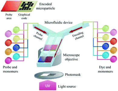 | ||
| Fig. 75 Encoded particles used for high throughput multiplex nucleotide diagnostics. Reproduced with permission from ref. 586. Copyright 2006 Macmillan Publishers. | ||
The advantage over other systems is that the probes were effectively printed directly into the encoded particles and only one fluorescent molecule was needed for both target identification and quantification. The technique succeeded in detecting DNA oligomer targets down to the picomolar level. Recently, other researchers designed special shaped particles obtained by CFL for the detection of some proteins. They were also used for the specific spatial sensing of ligands through development of polymeric substrates that contain a specific templating ligand: molecularly imprinted polymers emerging as a novel research area. With the help of microfluidic techniques the template was selectively removed from residual cavities and then the monodisperse MIP microbeads were used to detect the specific ligand molecule target,587 even in mixtures of various molecule analogs.588 With the rapid development and lasting improvement of encoded particles, we will witness the widespread use of microfluidically-synthesized encoded particles with faster response and improved accuracy in the future.
5.8. Multiplex protein measurement
Two main methods exist for measuring protein panels in a single assay: planar arrays and particle-based arrays.589 Planar arrays, also denominated micro-arrays, employ fixed panels of 100–1000 unique probes spatially segregated on a slide for a single assay. Although this method can measure multiplexed proteins on large scale, it provides limited flexibility for probe-set modification, due to the requirement of large quantities of reagents and because the detection can be expensive and time consuming.590,591 In contrast, particle-based arrays have some advantages over conventional planar arrays, such as improved scalability, shorter analysis time, and flexible probe set reconstruction (important to respond to evolving assay demands). Moreover, it requires less sample and reagents to analyze 100–1000 targets and it can combine different encoded particles, each identifying a single target, as a custom chip for tailored assays. They are particularly suitable for high throughput analysis of focused panels of biomolecules.381 However, recently, the low accuracy and high cost of microfluidic-synthesized particles for multiplex protein measurement have attracted more and more attention. We believe that customized particles obtained by an advanced microfluidic flow photolithography method will overcome these drawbacks, exhibit huge potential and make better accomplishment in future multiplex protein measurement.6. Conclusion and outlook
This review is intended to introduce microfluidics in an ordered comprehensive way and to inspire the researchers for the fabrication of functional macroporous particles. In addition, a section for current and future application fields is foreseen, with the focus on particle morphology design as a function of the application requirements. Currently exciting developments are published in the field of fabrication, functionalization and application of macroporous materials. In particular, micro-manufacturing and micro-machining contribute more and more to the creation of hierarchical porous materials, made from various compounds and composites. Hierarchical ordered structures inherently differ from monomodal ones by the co-existence of multiple pore scales. The embedded micropores and mesopores offer a higher surface area and pore volume, resulting in numerous reactive sites, size-selectivity for different kinds of molecules and a substantial higher interfacial area. When larger macropores can be incorporated, without collapsing the micro- and mesoporous structures, the resultant hierarchical porous materials can offset the diffusion limitations and improve the mass and energy exchange.592The fabrication of porous materials using microfluidic techniques addresses the drawbacks of traditional synthesis approaches. It provides accurate control of the particles' morphology in a highly reproductive manner. Microfluidic techniques also allow the space for further development with more complex configurations: from radially porous particles to ordered ones, from opened porous structures to closed ones, from regular porous spheres to irregular ones, from interconnected structures to multi-compartmentalized structures, from monomodal porous structures to hierarchical ones, etc. They have opened the way to the production of advanced materials such as inverse-opals, scaffolds and hierarchical porous materials, which would be difficult to generate otherwise. Flow lithography, as the result of simultaneous development of microfluidics and photolithography techniques, unlocks new possibilities for the synthesis of customized porous materials with a relatively wide range of morphologies and thus application fields. Microfluidic techniques allow particles to be fabricated with unprecedented control over their pore size with narrow distributions. They possess great potential for encapsulating a wide range of active materials, even living cells in biomedical applications. Nevertheless some drawbacks still exist, such as low throughput and tedious device preparation, limiting their wider range of applications. But this can be stated in many novel techniques and the research field is still developing. In this regard, multiple parallel microfluidic devices are currently considered as a practical but less efficient solution.593,594 Blocking phenomena occurring during fabrication still remain a challenge for microfluidic techniques. The existing methods for the minimization of blocking phenomena, such as surface modification, flow modulation and external force control, are rather sophisticated. A facile approach for minimizing this effect is still required.70 To date, one-step fabrication of macroporous particles has only rendered radially porous structures, whereas a combination of polymerization with sacrificial templates and wet etching processes results in various well ordered porous structures. Hierarchical porous structures are obtained by introducing sacrificial templating nanoparticles on different scales. However, modern microfluidics still looks for improvements. The main quest still remains how to simultaneously achieve accurate and independent control of the ordered hierarchical porous structures in one step.
In conclusion, future research will focus on the improvement of the device simplicity on one hand and on the particle morphology functional complexity on the other hand. This change undoubtedly conforms to the development of science from simple to complicated as well as from the shallower to the deeper. While initial inroads have been made, more work in the area of scale-up must still be done.
List of abbreviations
| 2D | Two-dimensional |
| 3D | Three-dimensional |
| AAm | Acrylamide |
| AIBN | Azobis(isobutyronitrile) |
| AR | Aspect ratio |
| BDK | 2,2-Dimethoxy-2-phenylacetophenone |
| BMA | Butyl methacrylate |
| BuAc | n-Butyl acetate |
| ccp | Cubic close packed |
| CFL | Continuous flow lithography |
| CPC | Colloidal photonic crystal |
| CTAB | Cetyltrimethylammonium |
| DAP | Diallyl phthalate |
| Darocur 1173 | 2-Hydroxy-2-methyl-1-phenyl-1-propanone |
| DBP | Diisobutyl phthalate |
| DCDMS | Dichlorodimethylsilane |
| DCM | Dichloromethane |
| DDP | Diisodecyl phthalate |
| DDS | Drug-delivery system |
| DEAP | 2,2-Diethoxyacetophenone |
| DEP | Diethyl phthalate |
| DMF | N,N-Dimethylformamide |
| DMPA | 2,2-Dimethoxy-2-phenylacetophenone |
| DOP | Dioctyl phthalate |
| DPPD | 2,2-Di(pro-2-ynyl)-propane-1,3-diol |
| DEX-MA | Dextran-methacrylate |
| EA | Ethyl acetate |
| EGDMA | Ethylene glycol dimethacrylate |
| EPTBC | Ethyleneoxide propyleneoxide tri-block copolymer |
| ETPTA | Ethoxylated trimethylolpropane triacrylate |
| FFD | Flow-focusing device |
| FFT | T-junction device |
| FITC-dextran | Fluorescein isothiocyanate-dextran |
| GLU | Glutaraldehyde |
| GMA | Glycidyl methacrylate |
| GMBS | N-Gamma-maleimido-butyryloxy-succinimide |
| HEM | Hydroxyethyl methacrylate |
| HF | Hydrofluoric acid |
| HIPE | High-internal-phase emulsion |
| HMPP | 2-Hydroxy-2-methyl-1-phenyl-1-propanone |
| HPCM | Hydrogel photonic crystal microparticles |
| HRP | Horseradish peroxidase |
| KPS | Potassium persulfate |
| LRL | Lock and release lithography |
| MAA | Methacrylic acid |
| MBAAm | N,N′-Methylene-bis-acrylamide |
| MEK | Methyl ethyl ketone |
| MIPB | Molecularly imprinted polymer bead |
| MMA | Methyl methacrylate |
| NIR | Near-infrared |
| NOA 61 | Mixture of trimethylolpropane diallyl ether, isophorone diisocyanate ester, trimethylolpropane tristhiol and a benzophenone photo-initiator |
| OY | 1,7-Octadiyne |
| NIPAm | N-Isopropylacrylamide |
| PBG | Photonic band gap |
| PCB | Photonic crystal bead |
| PCL | Poly(ε-caprolactone) |
| PCM | Phase change material |
| PDLA | Poly(D,L-lactide) |
| PDMS | Poly(dimethyl siloxane) |
| PEG | Poly(ethylene glycol) |
| PEG-40S | Poly(ethylene glycol)-40-stearate |
| PEGDA | Poly(ethylene glycol)diacrylate |
| PEO | Poly(ethylene oxide) |
| PGPR | Polyglycerol polyricinoleate |
| PhC | Photonic crystal |
| PIL | Polyionic liquid |
| PIL-IOM | Polyionic liquid inverse opaline microspheres |
| PLGA | Poly(D,L-lactide-co-glycolide) |
| PLLA | Poly(L-lactide) |
| Pluronic F108 | Ethylene oxide–propylene oxide–ethylene oxide tri-block copolymer |
| PMMA | Poly(methyl methacrylate) |
| pNIPAAm | Poly(N-isopropylacrylamide) |
| PPO | Poly(propylene oxide) |
| PSf | Polysulfone |
| PTE | Pentaerythritol triallyl ether |
| PVA | Poly(vinyl alcohol) |
| SCCB | Silica colloidal crystal bead |
| SDS | Sodium dodecyl sulfate |
| SERS | Surface-enhanced Raman scattering |
| SFIL | Stop flow interference lithography |
| SFL | Stop flow lithography |
| Span80 | Sorbitan mono-oleate |
| SPIONs | Superparamagnetic iron oxide nanoparticles |
| SPS | Sodium peroxodisulfate |
| SR454 | Ethoxylated-trimethylolpropane-triacrylate |
| TEMED | N,N,N′,N′-Tetramethylethylenediamine |
| TEOS | Tetraethyl orthosilicate |
| THF | Tetrahydrofuran |
| TPGDA | Tripropylene glycol diacrylate |
| TT | Pentaerythritol tetrakis-(3-mercaptopropionate) |
| TTT | Triallyl-135 triazine trione |
Appendix
| Morphology | Sb/group ref. | Method | Phase composition |
Q
d![[thin space (1/6-em)]](https://www.rsc.org/images/entities/char_2009.gif) : :![[thin space (1/6-em)]](https://www.rsc.org/images/entities/char_2009.gif) Qc or QI Qc or QI![[thin space (1/6-em)]](https://www.rsc.org/images/entities/char_2009.gif) : :![[thin space (1/6-em)]](https://www.rsc.org/images/entities/char_2009.gif) QM QM![[thin space (1/6-em)]](https://www.rsc.org/images/entities/char_2009.gif) : :![[thin space (1/6-em)]](https://www.rsc.org/images/entities/char_2009.gif) QO QO |
Porogen | Average particle diameter/μm | Average pore size/μm | Porosity | Specific surface area (SSA)/m2 g−1 | CV (%) | |||
|---|---|---|---|---|---|---|---|---|---|---|---|---|---|
| Surface | Internal | Inner (dispersed) | Outer (continuous) | Surface | Internal | ||||||||
| Smooth skin | Macropores | S. Dubinsky et al. | UV-induced polymerization with porogen | A mixture of GMA and porogen | Aqueous solution of PVA and surfactant or THF | 1![[thin space (1/6-em)]](https://www.rsc.org/images/entities/char_2009.gif) : :![[thin space (1/6-em)]](https://www.rsc.org/images/entities/char_2009.gif) 200 200 |
DBP/DOP 1![[thin space (1/6-em)]](https://www.rsc.org/images/entities/char_2009.gif) : :![[thin space (1/6-em)]](https://www.rsc.org/images/entities/char_2009.gif) 1 (v/v) 1 (v/v) |
About 58a | 0 | — | — | — | — |
| DOP (0.5 wt% Triton X-100) | About 63.5a | 0 | — | — | — | — | |||||||
| Gradient porous structures | T. Watanabe et al. | Selective solvent extraction | Sodium poly(styrenesulfonate) | Hexadecane and Span80 | 1![[thin space (1/6-em)]](https://www.rsc.org/images/entities/char_2009.gif) : :![[thin space (1/6-em)]](https://www.rsc.org/images/entities/char_2009.gif) 15–1 15–1![[thin space (1/6-em)]](https://www.rsc.org/images/entities/char_2009.gif) : :![[thin space (1/6-em)]](https://www.rsc.org/images/entities/char_2009.gif) 35 35 |
— | About 79a | 0 | 10–100 | 10–50% | — | <5 | |
| Macropores | J. Y. Sim et al. | Microfluidic molding | — | — | — | — | — | 0 | 0.166–0.2 | — | — | — | |
| Micro- to macropores | C. E. Udoh et al. | Selective solvent extraction | Polymer solution | Hexadecane with Span80 | Q d = 10 μL min−1; Qc = 50–90 μL min−1 | — | 50–200 | 0 | 1–100 | — | — | — | |
| Golf-ball-like dimples | Macropores | S.-H. Kim et al. | UV-induced polymerization with wet etching process | Silica–ETPTA and Darocur 1173 | Aqueous solution with Pluronic F108 | 1![[thin space (1/6-em)]](https://www.rsc.org/images/entities/char_2009.gif) : :![[thin space (1/6-em)]](https://www.rsc.org/images/entities/char_2009.gif) 100 100 |
— | About 110a | 0.14–0.21a | — | — | — | — |
| About 197a | 0.59–1.18a | — | — | — | — | ||||||||
| Macropores | K.-H. Hwangbo et al. | Selective solvent extraction | A mixture of DCM, polymer, and PCM | PVA aqueous solution | <1![[thin space (1/6-em)]](https://www.rsc.org/images/entities/char_2009.gif) : :![[thin space (1/6-em)]](https://www.rsc.org/images/entities/char_2009.gif) 500 500 |
— | 185–280 | 5–20a | 4.4–9.5a | — | — | — | |
| Macropores | J. H. Lee et al. | Solvent evaporation and phase separation | A mixture of PLGA, PCM, dichloromethane | PVA aqueous solution | — | — | About 235 ± 5 | 4.2–33.2a | Smaller than surface dimples | — | — | — | |
| Morphology | Sb/group ref. | Method | Phase composition |
Q
d![[thin space (1/6-em)]](https://www.rsc.org/images/entities/char_2009.gif) : :![[thin space (1/6-em)]](https://www.rsc.org/images/entities/char_2009.gif) Qc or QI Qc or QI![[thin space (1/6-em)]](https://www.rsc.org/images/entities/char_2009.gif) : :![[thin space (1/6-em)]](https://www.rsc.org/images/entities/char_2009.gif) QM QM![[thin space (1/6-em)]](https://www.rsc.org/images/entities/char_2009.gif) : :![[thin space (1/6-em)]](https://www.rsc.org/images/entities/char_2009.gif) QO QO |
Porogen | Average particle diameter/μm | Average pore size/μm | Porosity | Specific surface area (SSA)/m2 g−1 | CV (%) | ||
|---|---|---|---|---|---|---|---|---|---|---|---|---|
| Inner (dispersed) | Middle (dispersed) | Outer (continuous) | ||||||||||
| Opened macroporous spheres | J. X. Yun et al. | Cryo-polymerization | A mixture of MBAAm, TEMED, AAm, APS | — | Ethyl enanthate and Span 80 | 1![[thin space (1/6-em)]](https://www.rsc.org/images/entities/char_2009.gif) : :![[thin space (1/6-em)]](https://www.rsc.org/images/entities/char_2009.gif) 12–1 12–1![[thin space (1/6-em)]](https://www.rsc.org/images/entities/char_2009.gif) : :![[thin space (1/6-em)]](https://www.rsc.org/images/entities/char_2009.gif) 2 2 |
— | 800–1500 | 3–50 | 86.2% | — | — |
| S. Dubinsky et al. | UV-induced polymerization with porogen | A mixture of GMA, DMPA, EGDMA, porogen | — | PVA aqueous solution | 2![[thin space (1/6-em)]](https://www.rsc.org/images/entities/char_2009.gif) : :![[thin space (1/6-em)]](https://www.rsc.org/images/entities/char_2009.gif) 105 105 |
DEP | 75 | 0.033a | — | 28.7 | 1.0 | |
2![[thin space (1/6-em)]](https://www.rsc.org/images/entities/char_2009.gif) : :![[thin space (1/6-em)]](https://www.rsc.org/images/entities/char_2009.gif) 105 105 |
DBP | 74 | 0.107a | — | 13.9 | 2.9 | ||||||
1![[thin space (1/6-em)]](https://www.rsc.org/images/entities/char_2009.gif) : :![[thin space (1/6-em)]](https://www.rsc.org/images/entities/char_2009.gif) 15 15 |
DOP | 110 | 0.179a | — | 6.6 | 0.8 | ||||||
1![[thin space (1/6-em)]](https://www.rsc.org/images/entities/char_2009.gif) : :![[thin space (1/6-em)]](https://www.rsc.org/images/entities/char_2009.gif) 12 12 |
DDP | 131 | 0.250a | — | 3.4 | 2.7 | ||||||
| S.-H. Kim et al. | UV-induced polymerization with wet etching process | Silica-ETPTA and Darocur 1173 | — | Aqueous solution with Pluronic F108, BASF, EPTBC | 1![[thin space (1/6-em)]](https://www.rsc.org/images/entities/char_2009.gif) : :![[thin space (1/6-em)]](https://www.rsc.org/images/entities/char_2009.gif) 100 100 |
— | About 247.4a | About 0.15a | — | — | — | |
| W. J. Duncanson et al. | One step polymerization with porogen | DCM and PLA | — | PVA aqueous solution | — | Self-assembling perfluorinated-dendrimer–dye complex | About 45–60a | About 0.9–1.25a | — | — | <6 | |
| K. Jiang et al. | UV-induced polymerization with porogen | A mixture of GMA, SR454, DA, DMPA | — | PVA aqueous solution with Triton X-100 | 1![[thin space (1/6-em)]](https://www.rsc.org/images/entities/char_2009.gif) : :![[thin space (1/6-em)]](https://www.rsc.org/images/entities/char_2009.gif) 15 15 |
DA | About 77 ± 2 | 1.6 ± 0.6 | 44–50% | — | — | |
| H. Zhang et al. | Single emulsion template with porogen | A mixture of HEMA, MMA, BDK, PVP K30, PGPR, EGPDA | — | PVA aqueous solution with glycerol | 3![[thin space (1/6-em)]](https://www.rsc.org/images/entities/char_2009.gif) : :![[thin space (1/6-em)]](https://www.rsc.org/images/entities/char_2009.gif) 20 20 |
PVP K30 | 47.6–57.5 | About 1.1–2.5a | — | — | 3.5 | |
| M. T. Gokmen et al. | UV-induced polymerization of HIPE emulsion template | A mixture of EGDMA, GMA, PEO–PPO–PEO 2800, CaCl2·2H2O (HIPE) | — | PVA aqueous solution | 1![[thin space (1/6-em)]](https://www.rsc.org/images/entities/char_2009.gif) : :![[thin space (1/6-em)]](https://www.rsc.org/images/entities/char_2009.gif) 6 6 |
— | About 400 | About 15 | 78–87% | 16 | — | |
| J. B. Wacker et al. | Evaporation-induced consolidation and self-assembly | Silica colloid aqueous solution | — | Oleic acid | 1![[thin space (1/6-em)]](https://www.rsc.org/images/entities/char_2009.gif) : :![[thin space (1/6-em)]](https://www.rsc.org/images/entities/char_2009.gif) 100–1 100–1![[thin space (1/6-em)]](https://www.rsc.org/images/entities/char_2009.gif) : :![[thin space (1/6-em)]](https://www.rsc.org/images/entities/char_2009.gif) 5 5 |
— | About 13–130a | About 0.8a | — | — | — | |
| J. Wan et al. | UV-induced polymerization of three phase emulsion template | Pure nitrogen gas | Deionized water with SDS, DEAP, MBAAm, acylamide | Mineral oil with DEAP |
Q
w![[thin space (1/6-em)]](https://www.rsc.org/images/entities/char_2009.gif) : :![[thin space (1/6-em)]](https://www.rsc.org/images/entities/char_2009.gif) Qo = 1; P = 18 psi Qo = 1; P = 18 psi |
— | <210a | About 28a | — | — | — | |
| R. A. Prasath et al. | UV-induced polymerization and flow reaction | Thiol–ene monomers with π-bond, DMPA, porogen | — | SDS aqueous solution | 1![[thin space (1/6-em)]](https://www.rsc.org/images/entities/char_2009.gif) : :![[thin space (1/6-em)]](https://www.rsc.org/images/entities/char_2009.gif) 900–1 900–1![[thin space (1/6-em)]](https://www.rsc.org/images/entities/char_2009.gif) : :![[thin space (1/6-em)]](https://www.rsc.org/images/entities/char_2009.gif) 200 200 |
DOP, Xy, BuAc, a mixture of Xy and BuAc | 240–325 | 0.05–3 | — | 0–4.9 | — | |
| Thiol–yne monomers with π-bond, DMPA, porogen | — | 240–300 | 0.2–1 | — | 2.2–35.6 | — | ||||||
| Macroporous core–shell spheres | W.-C. Jeong et al. | Double emulsion template | PVA aqueous solution with FITC–dextran | pNIPAAm particle-dispersed mixture of DCM, hexane and ethyl cellulose | PVA aqueous solution | 3![[thin space (1/6-em)]](https://www.rsc.org/images/entities/char_2009.gif) : :![[thin space (1/6-em)]](https://www.rsc.org/images/entities/char_2009.gif) 7 7![[thin space (1/6-em)]](https://www.rsc.org/images/entities/char_2009.gif) : :![[thin space (1/6-em)]](https://www.rsc.org/images/entities/char_2009.gif) 60 60 |
— | About 455a | Sub- to a few micro-meters | — | — | — |
| X. Gong et al. | UV-induced polymerization and flow reaction | H2O2 solution with PVA | NOA 61 | Liquid paraffin | 3![[thin space (1/6-em)]](https://www.rsc.org/images/entities/char_2009.gif) : :![[thin space (1/6-em)]](https://www.rsc.org/images/entities/char_2009.gif) 6 6![[thin space (1/6-em)]](https://www.rsc.org/images/entities/char_2009.gif) : :![[thin space (1/6-em)]](https://www.rsc.org/images/entities/char_2009.gif) 4–1 4–1![[thin space (1/6-em)]](https://www.rsc.org/images/entities/char_2009.gif) : :![[thin space (1/6-em)]](https://www.rsc.org/images/entities/char_2009.gif) 2 2![[thin space (1/6-em)]](https://www.rsc.org/images/entities/char_2009.gif) : :![[thin space (1/6-em)]](https://www.rsc.org/images/entities/char_2009.gif) 4 4 |
— | About 50–200 | Several micro-meters to tens of micro-meters | 70% (max) | — | — | |
| TPGDA | Silicon oil | |||||||||||
| EGDMA | Silicon oil | |||||||||||
| S.-W. Choi et al. | Double emulsion template and fast solvent evaporation | PVA aqueous solution | A mixture of PLGA and DCM | PVA aqueous solution | 3![[thin space (1/6-em)]](https://www.rsc.org/images/entities/char_2009.gif) : :![[thin space (1/6-em)]](https://www.rsc.org/images/entities/char_2009.gif) 30 30![[thin space (1/6-em)]](https://www.rsc.org/images/entities/char_2009.gif) : :![[thin space (1/6-em)]](https://www.rsc.org/images/entities/char_2009.gif) 200 200 |
— | About 709.1 | About 1.5 | — | — | 1.7 | |
| Dense spheres with thin surface pores | C. Paquet et al. | Self-assembling of materials | Chloroform solvent with SPIONs and copolymer | — | PVA aqueous solution with glycerol | 1![[thin space (1/6-em)]](https://www.rsc.org/images/entities/char_2009.gif) : :![[thin space (1/6-em)]](https://www.rsc.org/images/entities/char_2009.gif) 400 400 |
— | About 113–131 | <1 | — | About 5.2 | 2–8 |
| Opened macroporous spheres | Toluene solvent with SPIONs and copolymer | |||||||||||
| Dense porous spheres | A mixture of THF and toluene with SPIONs and copolymer | |||||||||||
| More dense channel-like structure | Hexane solvent with SPIONs and copolymer | |||||||||||
| Macroporous rods | M. T. Gokmen et al. | UV-induced polymerization of HIPE emulsion template | A mixture of EGDMA, GMA, PEO–PPO–PEO 4400, CaCl2·2H2O (HIPE) | — | PVA aqueous solution | 4![[thin space (1/6-em)]](https://www.rsc.org/images/entities/char_2009.gif) : :![[thin space (1/6-em)]](https://www.rsc.org/images/entities/char_2009.gif) 75 75 |
— | About 200 | About 1.25a | — | — | — |
| J. B. Wacker et al. | Evaporation-induced consolidation and self-assembly | Silica colloid aqueous solution | — | Oleic acid | 1![[thin space (1/6-em)]](https://www.rsc.org/images/entities/char_2009.gif) : :![[thin space (1/6-em)]](https://www.rsc.org/images/entities/char_2009.gif) 100–1 100–1![[thin space (1/6-em)]](https://www.rsc.org/images/entities/char_2009.gif) : :![[thin space (1/6-em)]](https://www.rsc.org/images/entities/char_2009.gif) 5 5 |
— | About 45—100a | About 0.8a | — | — | — | |
| Sponge-like open-celled porous microgels (interconnected pores) | C.-L. Mou et al. | UV-induced polymerization and homogeneous emulsification | O/W emulsions with benzyl benzoate, soybean oil, PGPR, LR300, V-50, NIPAM, MBAAm, F-127, and glycerol | — | Soybean oil with PGPR | 1![[thin space (1/6-em)]](https://www.rsc.org/images/entities/char_2009.gif) : :![[thin space (1/6-em)]](https://www.rsc.org/images/entities/char_2009.gif) 12–1 12–1![[thin space (1/6-em)]](https://www.rsc.org/images/entities/char_2009.gif) : :![[thin space (1/6-em)]](https://www.rsc.org/images/entities/char_2009.gif) 1 1 |
Fine oil droplets (adding isopropanol or heat up) | — | About 8a | — | — | 1.6 |
| Pinecone-like structure at one end and a tip-shaped tail structure at another end (disconnected pores) | Deionized water with NIPAM, MBAAm, V-50, F-127 and glycerol | (Adding isopropanol) | — | — | — | — | 1.8 | |||||
| Morphology | Sb/group ref. | Method | Phase composition |
Q
d![[thin space (1/6-em)]](https://www.rsc.org/images/entities/char_2009.gif) : :![[thin space (1/6-em)]](https://www.rsc.org/images/entities/char_2009.gif) Qc or QI Qc or QI![[thin space (1/6-em)]](https://www.rsc.org/images/entities/char_2009.gif) : :![[thin space (1/6-em)]](https://www.rsc.org/images/entities/char_2009.gif) QM QM![[thin space (1/6-em)]](https://www.rsc.org/images/entities/char_2009.gif) : :![[thin space (1/6-em)]](https://www.rsc.org/images/entities/char_2009.gif) QO QO |
Porogen | Average swelling ratio | Average pore size/μm | Porosity | Specific surface area (SSA)/m2 g−1 | CV (%) | |
|---|---|---|---|---|---|---|---|---|---|---|---|
| Inner (dispersed) | Outer (continuous) | ||||||||||
| Highly interconnected and uniform macroporous scaffold | K. Chung et al. | Single emulsion templates | Nitrogen gas | Alginate solution with Pluronic F127 | P = 6 psi; Qc = 18 mL h−1 | — | 91.83 ± 6.02% | About 250 | 86.90 ± 5.09% | — | — |
| C.-C. Wang et al. | Single emulsion templates | Nitrogen gas | Alginate solution with acetic acid and Pluronic F127 | P = 5 psi; Qc = 12 mL h−1 | — | 2607.41 ± 340.10% | About 225a | 97.25 ± 0.84% | — | — | |
| A. van der Net et al. | Microfluidic foaming technique | Air | Solution A (AAm aqueous solution with MBAAm, TEMED, Lutesol® AT18) + solution B (an aqueous solution with Lutesol® AT18 and SPS) | 1![[thin space (1/6-em)]](https://www.rsc.org/images/entities/char_2009.gif) : :![[thin space (1/6-em)]](https://www.rsc.org/images/entities/char_2009.gif) 1 (QA = QB) 1 (QA = QB) |
— | — | About 207–353a | — | — | — | |
| C. Colosi et al. | Microfluidic foaming technique | Argon gas | An aqueous solution of PVA and CTABr | P = 67 kPa, Qc = 0.135 mL h−1 | — | — | 140 ± 17 | 63% | — | — | |
| M. Constantini et al. | Microfluidic polyHIPEs emulsions | A cyclohexane solution | An aqueous solution of DEX-MA with Irgacure 2959, APS, Pluronic F-68 | About 4![[thin space (1/6-em)]](https://www.rsc.org/images/entities/char_2009.gif) : :![[thin space (1/6-em)]](https://www.rsc.org/images/entities/char_2009.gif) 1 1 |
— | — | About 136–241 | About 80% | About 19–35 | — | |
| Highly order closed-cell polyhedral foam and closed-cell polyhedral foam | A. Quell et al. | Microfluidic polyHIPE emulsions | PolyHIPE monomers with KPS or AIBN | A mixture solution of styrene and divinylbenzene containing the surfactant Hypermer 2296 | — | — | — | 59–71 (KPS) or 57–75 (AIBN) | — | — | — |
| Morphology | Sb/group ref. | Method | Phase composition |
Q
d![[thin space (1/6-em)]](https://www.rsc.org/images/entities/char_2009.gif) : :![[thin space (1/6-em)]](https://www.rsc.org/images/entities/char_2009.gif) Qc or QI Qc or QI![[thin space (1/6-em)]](https://www.rsc.org/images/entities/char_2009.gif) : :![[thin space (1/6-em)]](https://www.rsc.org/images/entities/char_2009.gif) QM QM![[thin space (1/6-em)]](https://www.rsc.org/images/entities/char_2009.gif) : :![[thin space (1/6-em)]](https://www.rsc.org/images/entities/char_2009.gif) QO QO |
Porogen | Average particle diameter/μm | Average pore size/μm | Porosity | Specific surface area (SSA)/m2 g−1 | CV (%) | |
|---|---|---|---|---|---|---|---|---|---|---|---|
| Inner (dispersed) | Outer (continuous) | ||||||||||
| Highly ordered inverse opal structure | Y. Zhao et al. | Sacrificial template self-assembly, evaporation-induced consolidation and calcination | An aqueous suspension containing monodisperse polystyrene spheres and ultrafine silica particles | Silicon oil | — | — | About 270a | About 0.2a | — | — | — |
| J. Wang et al. | Sacrificial template self-assembly, evaporation-induced consolidation and wet etching process | An aqueous suspension containing monodisperse silica NPs | Silicon oil | 1![[thin space (1/6-em)]](https://www.rsc.org/images/entities/char_2009.gif) : :![[thin space (1/6-em)]](https://www.rsc.org/images/entities/char_2009.gif) 6 6 |
— | — | About 0.22b | — | — | — | |
| J. Cui et al. | Sacrificial template self-assembly, UV-induced polymerization and wet etching process | — | — | — | — | 0.3 | About 0.2a | — | — | — | |
| Densely packed opal cores and inverse-opal shells | B. Ye et al. | Sacrificial template self-assembly, UV-induced polymerization and selected etching process | — | — | — | — | — | About 0.2a | — | — | — |
| Highly ordered macroporous film | M. Elsayed et al. | Sacrificial template (efficient burst of templated bubbles) | Polymeric solution containing sodium alginate, PEG-40S and phospholipids | Gas | P = 95–165 kPa, Qc = 200 μL min−1 | — | — | 70 ± 30 μm to 122 ± 15 μm | — | — | — |
| Morphology | Sb/group ref. | Method | Phase composition |
Q
d![[thin space (1/6-em)]](https://www.rsc.org/images/entities/char_2009.gif) : :![[thin space (1/6-em)]](https://www.rsc.org/images/entities/char_2009.gif) Qc or QI Qc or QI![[thin space (1/6-em)]](https://www.rsc.org/images/entities/char_2009.gif) : :![[thin space (1/6-em)]](https://www.rsc.org/images/entities/char_2009.gif) QM QM![[thin space (1/6-em)]](https://www.rsc.org/images/entities/char_2009.gif) : :![[thin space (1/6-em)]](https://www.rsc.org/images/entities/char_2009.gif) QO QO |
Porogen | Average particle size/μm | Average pore size/μm | Porosity | Specific surface area (SSA)/m2 g−1 | CV (%) | |||
|---|---|---|---|---|---|---|---|---|---|---|---|---|---|
| Inner (dispersed) | Middle (dispersed) | Outer (continuous) | Large | Small | |||||||||
| a Measure (obtained by analyzing/measuring optical microscopy images/SEM). b Speculation. | |||||||||||||
| Microspheres with hollow interior and radially hierarchical porous shell | S.-W. Choi et al. | Double emulsions template and fast solvent evaporation | PVA aqueous solution | A homogenized W/O emulsion containing PVA and PLGA | PVA aqueous solution | 0.7![[thin space (1/6-em)]](https://www.rsc.org/images/entities/char_2009.gif) : :![[thin space (1/6-em)]](https://www.rsc.org/images/entities/char_2009.gif) 6 6![[thin space (1/6-em)]](https://www.rsc.org/images/entities/char_2009.gif) : :![[thin space (1/6-em)]](https://www.rsc.org/images/entities/char_2009.gif) 50 50 |
— | About 446 | About 4 | <1 | — | — | — |
| Microspheres with bimodal macropore–mesopore structure (radially hierarchical) | Z. Zhai et al. | Temperature-induced gelation | A silica sol aqueous solution containing MC, PEG, HCL and TEOS | — | A liquid paraffin solution containing Span 85 | 1![[thin space (1/6-em)]](https://www.rsc.org/images/entities/char_2009.gif) : :![[thin space (1/6-em)]](https://www.rsc.org/images/entities/char_2009.gif) 40 40 |
— | About 490 | About 0.1–1 | About 0.0138–0.0205 | — | About 309–390 | 2.1–2.5 |
| Multi-cored microcapsules with porous surface (radially hierarchical) | S.-H. Kim et al. | Double emulsion template, UV-induced polymerization and wet etching process | An aqueous solution of food coloring pigments or FITC-labeled dextran | A ETPTA suspension containing silica particles treated with DCDMS | An aqueous solution of ethyleneoxide–propylene oxide–ethylene oxide tri-block copolymer, BASF and Pluronic F2109 |
Q
M![[thin space (1/6-em)]](https://www.rsc.org/images/entities/char_2009.gif) : :![[thin space (1/6-em)]](https://www.rsc.org/images/entities/char_2009.gif) QI < 0.5 QI < 0.5 |
— | About 200–300a | About 100b | About 0.7a | — | — | — |
| Radially hierarchical interconnected porous spheres | N. J. Carroll et al. | Microfluidic templating and evaporation-induced consolidation | An aqueous solution with CTAB, TEOS, and HCl | Pure hexadecane oil | Hexadecane solution with ABIL EM 90 |
Q
M![[thin space (1/6-em)]](https://www.rsc.org/images/entities/char_2009.gif) : :![[thin space (1/6-em)]](https://www.rsc.org/images/entities/char_2009.gif) QI = 1 QI = 1![[thin space (1/6-em)]](https://www.rsc.org/images/entities/char_2009.gif) : :![[thin space (1/6-em)]](https://www.rsc.org/images/entities/char_2009.gif) 10 10 |
— | 7.7 ± 1 | Tens of nanometers | Single nanometer | — | About 650–1250 | — |
| Radially hierarchical porous microspheres | Y. Fan et al. | The synergistic effect between the sol–gel process and solvent extraction in droplets | Dichloromethane solution with PCL and TEOS | — | Mixture of PVA and ammonia solution | — | — | About 65 | 7.5a | — | — | 333.698 | — |
| Chitosan inverse opal scaffold with ordered hierarchical pores | S.-W. Choi et al. | Sacrificial template, heat treatment and sedimentation–evaporation method | A PCL solution in MC | — | PVA aqueous solution | — | — | 4.5 mm in diameter and 1.5 mm in thickness | About 110a | About 5a | — | — | <5 |
| Uniform microparticles with controllable highly interconnected hierarchical porous structures | M.-J. Zhang et al. | Double emulsion template and mass transfer | An aqueous solution containing glycerin and Pluronic F127 | MMA containing EGDMA, PGPR, and HMPP | An aqueous solution containing glycerin and Pluronic F127 | — | — | About 217a | About 130–167a | About 2a | 0–50% | — | — |
| Hierarchical porous silk-based materials | M. R. Sommer et al. | Sacrificial template and 3D printing technology | DCM solution with PCL | — | PVA aqueous solution | Q d = 1–5 mL h−1; Qc = 5–30 mL h−1 | — | — | <335b | — | — | — | — |
Acknowledgements
This work is supported by The National Basic Research Program of China (973 Program, 2014CB748500), the National Natural Science Foundation of China (51406057, 51578239, 51322805) and the Research Fund for the Doctoral Program of Higher Education of China (20130074120019). Besides, it is also supported by The UK Engineering and Physical Sciences Research Council, EPSRC (EP/N009924/1).References
- H. P. Hentze and M. Antonietti, Rev. Mol. Biotechnol., 2002, 90, 27–53 CrossRef CAS PubMed.
- S. Xie, R. W. Allington, J. M. J. Fréchet and F. Svec, in Modern Advances in Chromatography, ed. R. Freitag, Springer, Berlin, Heidelberg, 2002, pp. 87–125 Search PubMed.
- Y. Lumelsky, J. Zoldan, S. Levenberg and M. S. Silverstein, Macromolecules, 2008, 41, 1469–1474 CrossRef CAS.
- F. S. Macintyre and D. C. Sherrington, Macromolecules, 2004, 37, 7628–7636 CrossRef CAS.
- M. Slater, M. Snauko, F. Svec and J. M. J. Fréchet, Anal. Chem., 2006, 78, 4969–4975 CrossRef CAS PubMed.
- N. Fontanals, R. M. Marcé, P. A. G. Cormack, D. C. Sherrington and F. Borrull, J. Chromatogr. A, 2008, 1191, 118–124 CrossRef CAS PubMed.
- D. Hudson, J. Comb. Chem., 1999, 1, 333–360 CrossRef CAS PubMed.
- T. P. Rao, R. S. Praveen and S. Daniel, Crit. Rev. Anal. Chem., 2004, 34, 177–193 CrossRef CAS.
- L. Leeb, P. Gmeiner and S. Löber, QSAR Comb. Sci., 2007, 26, 1145–1150 CAS.
- N. Miletić, Z. Vuković, A. Nastasović and K. Loos, J. Mol. Catal. B: Enzym., 2009, 56, 196–201 CrossRef.
- R. Haag and S. Roller, in Immobilized Catalysts: Solid Phases, Immobilization and Applications, ed. A. Kirschning, Springer, Berlin, Heidelberg, 2004, pp. 1–42 Search PubMed.
- F. Švec, J. Hradil, J. Čoupek and J. Kálal, Angew. Makromol. Chem., 1975, 48, 135–143 CrossRef.
- Z. Pelzbauer, J. Lukáš, F. Švec and J. Kálal, J. Chromatogr. A, 1979, 171, 101–107 CrossRef CAS.
- D. Horák, Z. Pelzbauer, M. Bleha, M. Ilavský, F. Švec and J. Kálal, J. Appl. Polym. Sci., 1981, 26, 411–421 CrossRef.
- W. T. Ford, J. Lee and M. Tomoi, Macromolecules, 1982, 15, 1246–1251 CrossRef CAS.
- P. Reinholdsson, T. Hargitai, R. Isaksson and B. Törnell, Angew. Makromol. Chem., 1991, 192, 113–132 CrossRef CAS.
- S. Dubinsky, J. I. Park, I. Gourevich, C. Chan, M. Deetz and E. Kumacheva, Macromolecules, 2009, 42, 1990–1994 CrossRef CAS.
- H. Zhang, X.-J. Ju, R. Xie, C.-J. Cheng, P.-W. Ren and L.-Y. Chu, J. Colloid Interface Sci., 2009, 336, 235–243 CrossRef CAS PubMed.
- M. T. Gokmen, W. Van Camp, P. J. Colver, S. A. F. Bon and F. E. Du Prez, Macromolecules, 2009, 42, 9289–9294 CrossRef CAS.
- W.-Q. Zhou, T.-Y. Gu, Z.-G. Su and G.-H. Ma, Eur. Polym. J., 2007, 43, 4493–4502 CrossRef CAS.
- D. Horák, Z. Pelzbauer, F. Ŝvec and J. Kálal, J. Appl. Polym. Sci., 1981, 26, 3205–3211 CrossRef.
- J.-S. Yu, S. Kang, S. B. Yoon and G. Chai, J. Am. Chem. Soc., 2002, 124, 9382–9383 CrossRef CAS PubMed.
- H. Strohm and P. Lobmann, J. Mater. Chem., 2004, 14, 2667–2673 RSC.
- A. M. Todea, A. Merca, H. Bögge, T. Glaser, J. M. Pigga, M. L. K. Langston, T. Liu, R. Prozorov, M. Luban, C. Schröder, W. H. Casey and A. Müller, Angew. Chem., Int. Ed., 2010, 49, 514–519 CrossRef CAS PubMed.
- F. Li, J. He, W. L. Zhou and J. B. Wiley, J. Am. Chem. Soc., 2003, 125, 16166–16167 CrossRef CAS PubMed.
- J. Li and Y. Zhang, Chem. Mater., 2007, 19, 2581–2584 CrossRef CAS.
- D. Lee and D. A. Weitz, Small, 2009, 5, 1932–1935 CrossRef CAS PubMed.
- C.-C. Wang, K.-C. Yang, K.-H. Lin, H.-C. Liu and F.-H. Lin, Biomaterials, 2011, 32, 7118–7126 CrossRef CAS PubMed.
- M. Costantini, C. Colosi, J. Guzowski, A. Barbetta, J. Jaroszewicz, W. Święszkowski, M. Dentini and P. Garstecki, J. Mater. Chem. B, 2014, 2, 2290–2300 RSC.
- D. Eisenberg, P. Prinsen, N. J. Geels, W. Stroek, N. Yan, B. Hua, J.-L. Luo and G. Rothenberg, RSC Adv., 2016, 6, 80398–80407 RSC.
- W. C. Yoo and A. Stein, Chem. Mater., 2011, 23, 1761–1767 CrossRef CAS.
- V. Polshettiwar, D. Cha, X. Zhang and J. M. Basset, Angew. Chem., Int. Ed., 2010, 49, 9652–9656 CrossRef CAS PubMed.
- X. Du and J. He, Langmuir, 2010, 26, 10057–10062 CrossRef CAS PubMed.
- X. Du and J. He, Langmuir, 2011, 27, 2972–2979 CrossRef CAS PubMed.
- X. Du and J. He, J. Colloid Interface Sci., 2010, 345, 269–277 CrossRef CAS PubMed.
- J. Wu, Y.-J. Zhu, S.-W. Cao and F. Chen, Adv. Mater., 2010, 22, 749–753 CrossRef CAS PubMed.
- X. Guo, Y. Deng, B. Tu and D. Zhao, Langmuir, 2010, 26, 702–708 CrossRef CAS PubMed.
- F. Iskandar, Mikrajuddin and K. Okuyama, Nano Lett., 2001, 1, 231–234 CrossRef CAS.
- F. Iskandar, Mikrajuddin and K. Okuyama, Nano Lett., 2002, 2, 389–392 CrossRef CAS.
- M. Abdullah, F. Iskandar, S. Shibamoto, T. Ogi and K. Okuyama, Acta Mater., 2004, 52, 5151–5156 CrossRef CAS.
- A. B. D. Nandiyanto, F. Iskandar and K. Okuyama, Chem. Lett., 2008, 37, 1040–1041 CrossRef CAS.
- C. Zhang, T. Hou, J. Chen and L. Wen, Particuology, 2010, 8, 447–452 CrossRef CAS.
- H. Zhang, G. C. Hardy, M. J. Rosseinsky and A. I. Cooper, Adv. Mater., 2003, 15, 78–81 CrossRef CAS.
- J.-G. Wang, H.-J. Zhou, P.-C. Sun, D.-T. Ding and T.-H. Chen, Chem. Mater., 2010, 22, 3829–3831 CrossRef CAS.
- L. Chen, G. Zhu, D. Zhang, H. Zhao, M. Guo, W. Shi and S. Qiu, J. Mater. Chem., 2009, 19, 2013–2017 RSC.
- M. U. Martines, E. Yeong, M. Persin, A. Larbot, W. F. Voorhout, C. K. U. Kübel, P. Kooyman and E. Prouzet, C. R. Chim., 2005, 8, 627–634 CrossRef CAS.
- X. Du and J. He, Nanoscale, 2011, 3, 3984–4002 RSC.
- F. Svec and J. M. J. Fréchet, Science, 1996, 273, 205–211 CAS.
- A. J. Jose, S. Ogawa and M. Bradley, Polymer, 2005, 46, 2880–2888 CrossRef CAS.
- S. Durie, K. Jerabek, C. Mason and D. C. Sherrington, Macromolecules, 2002, 35, 9665–9672 CrossRef CAS.
- V. P. Shastri, I. Martin and R. Langer, Proc. Natl. Acad. Sci. U. S. A., 2000, 97, 1970–1975 CrossRef CAS.
- K. Ogino, H. Sato, K. Tsuchiya, H. Suzuki and S. Moriguchi, J. Chromatogr. A, 1995, 699, 59–66 CrossRef CAS.
- D. C. Sherrington, Chem. Commun., 1998, 2275–2286 RSC.
- D. Dendukuri, D. C. Pregibon, J. Collins, T. A. Hatton and P. S. Doyle, Nat. Mater., 2006, 5, 365–369 CrossRef CAS PubMed.
- O. Okay, Prog. Polym. Sci., 2000, 25, 711–779 CrossRef CAS.
- D. Mark, S. Haeberle, G. Roth, F. von Stetten and R. Zengerle, Chem. Soc. Rev., 2010, 39, 1153–1182 RSC.
- P. N. Nge, C. I. Rogers and A. T. Woolley, Chem. Rev., 2013, 113, 2550–2583 CrossRef CAS PubMed.
- M. T. Gokmen and F. E. Du Prez, Prog. Polym. Sci., 2012, 37, 365–405 CrossRef CAS.
- D. Wu, F. Xu, B. Sun, R. Fu, H. He and K. Matyjaszewski, Chem. Rev., 2012, 112, 3959–4015 CrossRef CAS PubMed.
- J. H. Moon and S. Yang, Chem. Rev., 2010, 110, 547–574 CrossRef CAS PubMed.
- J. Hu, M. Chen, X. Fang and L. Wu, Chem. Soc. Rev., 2011, 40, 5472–5491 RSC.
- A. Stein, B. E. Wilson and S. G. Rudisill, Chem. Soc. Rev., 2013, 42, 2763–2803 RSC.
- Y. Liu, J. Goebl and Y. Yin, Chem. Soc. Rev., 2013, 42, 2610–2653 RSC.
- N. D. Petkovich and A. Stein, Chem. Soc. Rev., 2013, 42, 3721–3739 RSC.
- A. D. Roberts, X. Li and H. Zhang, Chem. Soc. Rev., 2014, 43, 4341–4356 RSC.
- C. M. A. Parlett, K. Wilson and A. F. Lee, Chem. Soc. Rev., 2013, 42, 3876–3893 RSC.
- C. Triantafillidis, M. S. Elsaesser and N. Husing, Chem. Soc. Rev., 2013, 42, 3833–3846 RSC.
- A. Walther and A. H. E. Müller, Chem. Rev., 2013, 113, 5194–5261 CrossRef CAS PubMed.
- E. Tumarkin and E. Kumacheva, Chem. Soc. Rev., 2009, 38, 2161–2168 RSC.
- S. Marre and K. F. Jensen, Chem. Soc. Rev., 2010, 39, 1183–1202 RSC.
- S.-H. Kim, J.-M. Lim, S.-K. Lee, C.-J. Heo and S.-M. Yang, Soft Matter, 2010, 6, 1092–1110 RSC.
- J. H. Kim, T. Y. Jeon, T. M. Choi, T. S. Shim, S.-H. Kim and S.-M. Yang, Langmuir, 2013, 30, 1473–1488 CrossRef PubMed.
- W. Engl, R. Backov and P. Panizza, Curr. Opin. Colloid Interface Sci., 2008, 13, 206–216 CrossRef CAS.
- W. Drenckhan and D. Langevin, Curr. Opin. Colloid Interface Sci., 2010, 15, 341–358 CrossRef CAS.
- A. Testouri, L. Arriaga, C. Honorez, M. Ranft, J. Rodrigues, A. van der Net, A. Lecchi, A. Salonen, E. Rio and R.-M. Guillermic, Colloids Surf., A, 2012, 413, 17–24 CrossRef CAS.
- C. A. Serra and Z. Chang, Chem. Eng. Technol., 2008, 31, 1099–1115 CrossRef CAS.
- Y. Xia and G. M. Whitesides, Angew. Chem., Int. Ed., 1998, 37, 550–575 CrossRef CAS.
- D. C. Duffy, J. C. McDonald, O. J. A. Schueller and G. M. Whitesides, Anal. Chem., 1998, 70, 4974–4984 CrossRef CAS PubMed.
- A. S. Utada, E. Lorenceau, D. R. Link, P. D. Kaplan, H. A. Stone and D. A. Weitz, Science, 2005, 308, 537–541 CrossRef CAS PubMed.
- E. Lorenceau, A. S. Utada, D. R. Link, G. Cristobal, M. Joanicot and D. A. Weitz, Langmuir, 2005, 21, 9183–9186 CrossRef CAS PubMed.
- A. Utada, L.-Y. Chu, A. Fernandez-Nieves, D. Link, C. Holtze and D. Weitz, MRS Bull., 2007, 32, 702–708 CrossRef CAS.
- P. K. Yuen, Lab Chip, 2008, 8, 1374–1378 RSC.
- P. K. Yuen, J. T. Bliss, C. C. Thompson and R. C. Peterson, Lab Chip, 2009, 9, 3303–3305 RSC.
- P. K. Yuen and V. N. Goral, Lab Chip, 2010, 10, 384–387 RSC.
- A. R. Abate, D. Lee, T. Do, C. Holtze and D. A. Weitz, Lab Chip, 2008, 8, 516–518 RSC.
- T. Nisisako and T. Torii, Lab Chip, 2008, 8, 287–293 RSC.
- H. Keng-Shiang, L. Ming-Kai, W. Chun-Han, Y. Yu-Tang and L. Yu-Cheng, J. Micromech. Microeng., 2007, 17, 1428–1434 CrossRef.
- M. Miyazaki, T. Honda, H. Nakamura and H. Maeda, Chem. Eng. Technol., 2007, 30, 300–304 CrossRef CAS.
- H. Becker and C. Gärtner, Anal. Bioanal. Chem., 2008, 390, 89–111 CrossRef CAS PubMed.
- M. Bouquey, C. Serra, N. Berton, L. Prat and G. Hadziioannou, Chem. Eng. J., 2008, 135, S93–S98 CrossRef CAS.
- C. Serra, N. Berton, M. Bouquey, L. Prat and G. Hadziioannou, Langmuir, 2007, 23, 7745–7750 CrossRef CAS PubMed.
- Z. Chang, C. A. Serra, M. Bouquey, L. Prat and G. Hadziioannou, Lab Chip, 2009, 9, 3007–3011 RSC.
- C. Ohm, C. Serra and R. Zentel, Adv. Mater., 2009, 21, 4859–4862 CrossRef CAS PubMed.
- C. Zhenqi, A. S. Christophe, B. Michel, K. Isabelle, L. Shuning and J. M. Köhler, Nanotechnology, 2010, 21, 015605 CrossRef PubMed.
- A. Terray and S. J. Hart, Lab Chip, 2010, 10, 1729–1731 RSC.
- J. Seidl, J. Malinský, K. Dušek and W. Heitz, Fortschritte der Hochpolymeren-Forschung, Springer, Berlin, Heidelberg, 1967, pp. 113–213 Search PubMed.
- M. J. Beneš, D. Horák and F. Svec, J. Sep. Sci., 2005, 28, 1855–1875 CrossRef.
- E. C. Peters, M. Petro, F. Svec and J. M. J. Fréchet, Anal. Chem., 1997, 69, 3646–3649 CrossRef CAS PubMed.
- E. C. Peters, F. Svec and J. M. J. Fréchet, Adv. Mater., 1999, 11, 1169–1181 CrossRef CAS.
- C. Yu, M. Xu, F. Svec and J. M. J. Fréchet, J. Polym. Sci., Part A: Polym. Chem., 2002, 40, 755–769 CrossRef CAS.
- C. Yu, M. H. Davey, F. Svec and J. M. J. Fréchet, Anal. Chem., 2001, 73, 5088–5096 CrossRef CAS PubMed.
- J. Fréchet, Electrophoresis, 2001, 22, 3959–3967 CrossRef.
- Á. Sáfrány, B. Beiler, K. László and F. Svec, Polymer, 2005, 46, 2862–2871 CrossRef.
- J. Ugelstad, K. H. Kaggerud, F. K. Hansen and A. Berge, Makromol. Chem., 1979, 180, 737–744 CrossRef CAS.
- J. Ugelstad, L. Soderberg, A. Berge and J. Bergstrom, Nature, 1983, 303, 95–96 CrossRef.
- C. M. Cheng, F. J. Micale, J. W. Vanderhoff and M. S. El-Aasser, J. Polym. Sci., Part A: Polym. Chem., 1992, 30, 235–244 CrossRef CAS.
- C. M. Cheng, J. W. Vanderhoff and M. S. El-Aasser, J. Polym. Sci., Part A: Polym. Chem., 1992, 30, 245–256 CrossRef CAS.
- W. H. Li and H. D. Stöver, J. Polym. Sci., Part A: Polym. Chem., 1998, 36, 1543–1551 CrossRef CAS.
- E. Vivaldo-Lima, P. E. Wood, A. E. Hamielec and A. Penlidis, Ind. Eng. Chem. Res., 1997, 36, 939–965 CrossRef CAS.
- J. Haginaka, J. Chromatogr. B: Anal. Technol. Biomed. Life Sci., 2008, 866, 3–13 CrossRef CAS PubMed.
- H. Kawaguchi, Prog. Polym. Sci., 2000, 25, 1171–1210 CrossRef CAS.
- P. J. Dowding and B. Vincent, Colloids Surf., A, 2000, 161, 259–269 CrossRef CAS.
- K. N. N. Jayachandran and P. R. Chatterji, J. Macromol. Sci., Part C, 2001, 41, 79–94 CrossRef.
- S. Kawaguchi and K. Ito, in Polymer Particles, ed. M. Okubo, Springer, Berlin, Heidelberg, 2005, pp. 299–328 Search PubMed.
- L. Barner, Adv. Mater., 2009, 21, 2547–2553 CrossRef CAS.
- A. Pich and W. Richtering, in Chemical Design of Responsive Microgels, ed. A. Pich and W. Richtering, Springer, Berlin, Heidelberg, 2011, pp. 1–37 Search PubMed.
- G. T. Vladisavljević and R. A. Williams, Adv. Colloid Interface Sci., 2005, 113, 1–20 CrossRef PubMed.
- S. van der Graaf, C. Schroën and R. Boom, J. Membr. Sci., 2005, 251, 7–15 CrossRef CAS.
- J. L. Steinbacher and D. T. McQuade, J. Polym. Sci., Part A: Polym. Chem., 2006, 44, 6505–6533 CrossRef CAS.
- J. K. Oh, R. Drumright, D. J. Siegwart and K. Matyjaszewski, Prog. Polym. Sci., 2008, 33, 448–477 CrossRef CAS.
- F. Svec and J. M. J. Frechet, Anal. Chem., 1992, 64, 820–822 CrossRef CAS.
- F. Svec and J. M. J. Frechet, Chem. Mater., 1995, 7, 707–715 CrossRef CAS.
- M. Jancǒ, S. Xie, D. S. Peterson, R. W. Allington, F. Svec and J. M. J. Fréchet, J. Sep. Sci., 2002, 25, 909–916 CrossRef.
- G. Guiochon, J. Chromatogr. A, 2007, 1168, 101–168 CrossRef CAS PubMed.
- B. Paredes, S. González, M. Rendueles and J. M. Díaz, Sep. Purif. Technol., 2004, 40, 243–250 CrossRef CAS.
- S. Xu, Z. Nie, M. Seo, P. Lewis, E. Kumacheva, H. A. Stone, P. Garstecki, D. B. Weibel, I. Gitlin and G. M. Whitesides, Angew. Chem., Int. Ed., 2005, 44, 724–728 CrossRef CAS PubMed.
- M. Seo, Z. Nie, S. Xu, M. Mok, P. C. Lewis, R. Graham and E. Kumacheva, Langmuir, 2005, 21, 11614–11622 CrossRef CAS PubMed.
- Z. Nie, S. Xu, M. Seo, P. C. Lewis and E. Kumacheva, J. Am. Chem. Soc., 2005, 127, 8058–8063 CrossRef CAS PubMed.
- P. C. Lewis, R. R. Graham, Z. Nie, S. Xu, M. Seo and E. Kumacheva, Macromolecules, 2005, 38, 4536–4538 CrossRef CAS.
- T. Nisisako, T. Torii and T. Higuchi, Chem. Eng. J., 2004, 101, 23–29 CrossRef CAS.
- W. J. Jeong, J. Y. Kim, J. Choo, E. K. Lee, C. S. Han, D. J. Beebe, G. H. Seong and S. H. Lee, Langmuir, 2005, 21, 3738–3741 CrossRef CAS PubMed.
- D. Horák, F. Švec, M. Bleha and J. Kálal, Angew. Makromol. Chem., 1981, 95, 109–115 CrossRef.
- S. Dubinsky, H. Zhang, Z. Nie, I. Gourevich, D. Voicu, M. Deetz and E. Kumacheva, Macromolecules, 2008, 41, 3555–3561 CrossRef CAS.
- J. Wan, A. Bick, M. Sullivan and H. A. Stone, Adv. Mater., 2008, 20, 3314–3318 CrossRef CAS.
- W. H. Tan and S. Takeuchi, Adv. Mater., 2007, 19, 2696–2701 CrossRef CAS.
- D. Štefanec and P. Krajnc, React. Funct. Polym., 2005, 65, 37–45 CrossRef.
- D. Horák, F. Švec, M. Ilavský, M. Bleha, J. Baldrián and J. Kálal, Angew. Makromol. Chem., 1981, 95, 117–127 CrossRef.
- A. G. Mikos, G. Sarakinos, S. M. Leite, J. P. Vacant and R. Langer, Biomaterials, 1993, 14, 323–330 CrossRef CAS PubMed.
- T. Watanabe, C. G. Lopez, J. F. Douglas, T. Ono and J. O. T. Cabral, Langmuir, 2014, 30, 2470–2479 CrossRef CAS PubMed.
- J. Y. Sim, J. H. Choi, J. M. Lim, S. Cho, S. H. Kim and S. M. Yang, Small, 2014, 10, 3979–3985 CrossRef CAS PubMed.
- C. E. Udoh, V. Garbin and J. T. Cabral, Langmuir, 2016, 32, 8131–8140 CrossRef CAS PubMed.
- M. Okubo, Y. Murakami and T. Fujiwara, Colloid Polym. Sci., 1996, 274, 520–524 CAS.
- M. Okubo, A. Yamaguchi and T. Fujiwara, Colloid Polym. Sci., 1999, 277, 1005–1008 CAS.
- T. Fujibayashi, Y. Komatsu, N. Konishi, H. Yamori and M. Okubo, Ind. Eng. Chem. Res., 2008, 47, 6445–6449 CrossRef CAS.
- S.-H. Kim, J. Y. Sim, J.-M. Lim and S.-M. Yang, Angew. Chem., Int. Ed., 2010, 49, 3786–3790 CrossRef CAS PubMed.
- J. Choi, W.-P. Jeon and H. Choi, Phys. Fluids, 2006, 18, 041702 CrossRef.
- D. Falconnet, G. Csucs, H. Michelle Grandin and M. Textor, Biomaterials, 2006, 27, 3044–3063 CrossRef CAS PubMed.
- U. H. F. Bunz, Adv. Mater., 2006, 18, 973–989 CrossRef CAS.
- M. R. Kim, S. Lee, J.-K. Park and K. Y. Cho, Chem. Commun., 2010, 46, 7433–7435 RSC.
- M. Okubo, T. Fujiwara and A. Yamaguchi, Colloid Polym. Sci., 1998, 276, 186–189 CAS.
- N. Konishi, T. Fujibayashi, T. Tanaka, H. Minami and M. Okubo, Polym. J., 2010, 42, 66–71 CrossRef CAS.
- Y. K. Takahara, S. Ikeda, S. Ishino, K. Tachi, K. Ikeue, T. Sakata, T. Hasegawa, H. Mori, M. Matsumura and B. Ohtani, J. Am. Chem. Soc., 2005, 127, 6271–6275 CrossRef CAS PubMed.
- Y. K. Takahara, S. Ikeda, K. Tachi, T. Sakata, T. Hasegawa, H. Mori, M. Matsumura and B. Ohtani, Chem. Commun., 2005, 4205–4207 RSC.
- S.-H. Kim, C.-J. Heo, S. Y. Lee, G.-R. Yi and S.-M. Yang, Chem. Mater., 2007, 19, 4751–4760 CrossRef CAS.
- S.-H. Kim, J. Shim, J.-M. Lim, S. Lee and S.-M. Yang, New J. Phys., 2009, 11, 075014 CrossRef.
- S. H. Kim, S. J. Jeon, G. R. Yi, C. J. Heo, J. H. Choi and S. M. Yang, Adv. Mater., 2008, 20, 1649–1655 CrossRef CAS.
- S.-H. Kim, G.-R. Yi, K. H. Kim and S.-M. Yang, Langmuir, 2008, 24, 2365–2371 CrossRef CAS PubMed.
- S.-H. Kim, S.-H. Kim and S.-M. Yang, Adv. Mater., 2009, 21, 3771–3775 CrossRef CAS.
- S.-H. Kim, J.-M. Lim, W. C. Jeong, D.-G. Choi and S.-M. Yang, Adv. Mater., 2008, 20, 3211–3217 CrossRef CAS.
- S.-H. Kim, S. Y. Lee and S.-M. Yang, Angew. Chem., Int. Ed., 2010, 49, 2535–2538 CrossRef CAS PubMed.
- K.-H. Hwangbo, M. R. Kim, C.-S. Lee and K. Y. Cho, Soft Matter, 2011, 7, 10874–10878 RSC.
- J. H. Lee, C.-S. Lee and K. Y. Cho, ACS Appl. Mater. Interfaces, 2014, 6, 16493–16497 CAS.
- X. Gong, W. Wen and P. Sheng, Langmuir, 2009, 25, 7072–7077 CrossRef CAS PubMed.
- R. A. Prasath, M. T. Gokmen, P. Espeel and F. E. Du Prez, Polym. Chem., 2010, 1, 685–692 RSC.
- A. G. Lee, C. P. Arena, D. J. Beebe and S. P. Palecek, Biomacromolecules, 2010, 11, 3316–3324 CrossRef CAS PubMed.
- J. B. Wacker, V. K. Parashar and M. A. M. Gijs, Langmuir, 2011, 27, 4380–4385 CrossRef CAS PubMed.
- C. Paquet, Z. J. Jakubek and B. Simard, ACS Appl. Mater. Interfaces, 2012, 4, 4934–4941 CAS.
- J. Yun, C. Tu, D.-Q. Lin, L. Xu, Y. Guo, S. Shen, S. Zhang, K. Yao, Y.-X. Guan and S.-J. Yao, J. Chromatogr. A, 2012, 1247, 81–88 CrossRef CAS PubMed.
- W. J. Duncanson, M. Zieringer, O. Wagner, J. N. Wilking, A. Abbaspourrad, R. Haag and D. A. Weitz, Soft Matter, 2012, 8, 10636–10640 RSC.
- W.-C. Jeong, S.-H. Kim and S.-M. Yang, ACS Appl. Mater. Interfaces, 2014, 6, 826–832 CAS.
- C.-L. Mou, X.-J. Ju, L. Zhang, R. Xie, W. Wang, N.-N. Deng, J. Wei, Q. Chen and L.-Y. Chu, Langmuir, 2014, 30, 1455–1464 CrossRef CAS PubMed.
- S. Wang, C. Liu, H. Wang, G. Chen, M. Cong, W. Song, Q. Jia, S. Xu and W. Xu, ACS Appl. Mater. Interfaces, 2014, 6, 11706–11713 CAS.
- Y. Yang, N. Bajaj, P. Xu, K. Ohn, M. D. Tsifansky and Y. Yeo, Biomaterials, 2009, 30, 1947–1953 CrossRef CAS PubMed.
- H.-R. Lin, C.-J. Kuo, C. Y. Yang, S.-Y. Shaw and Y.-J. Wu, J. Biomed. Mater. Res., 2002, 63, 271–279 CrossRef CAS PubMed.
- S.-W. Choi, Y. Zhang and Y. Xia, Adv. Funct. Mater., 2009, 19, 2943–2949 CrossRef CAS PubMed.
- S. E. Bae, J. S. Son, K. Park and D. K. Han, J. Controlled Release, 2009, 133, 37–43 CrossRef CAS PubMed.
- K. Naidoo, H. Rolfes, K. Easton, S. Moolman, A. Chetty, W. Richter and R. Nilen, Mater. Lett., 2008, 62, 252–254 CrossRef CAS.
- K. Jiang, A. Sposito, J. Liu, S. R. Raghavan and D. L. DeVoe, Polymer, 2012, 53, 5469–5475 CrossRef CAS.
- R. K. Shah, H. C. Shum, A. C. Rowat, D. Lee, J. J. Agresti, A. S. Utada, L.-Y. Chu, J.-W. Kim, A. Fernandez-Nieves, C. J. Martinez and D. A. Weitz, Mater. Today, 2008, 11, 18–27 CrossRef CAS.
- H. Becker and C. Gärtner, Electrophoresis, 2000, 21, 12–26 CrossRef CAS PubMed.
- J. Liu, C.-F. Chen, C.-W. Chang and D. L. DeVoe, Biosens. Bioelectron., 2010, 26, 182–188 CrossRef CAS PubMed.
- R. Mallik and D. S. Hage, Journal of separation science, 2006, 29, 1686–1704 CrossRef CAS PubMed.
- L. Y. Chu, J. W. Kim, R. K. Shah and D. A. Weitz, Adv. Funct. Mater., 2007, 17, 3499–3504 CrossRef CAS.
- M. V. Sefton, L. Kharlip, V. Horvath and T. Roberts, J. Controlled Release, 1992, 19, 289–297 CrossRef CAS.
- N. R. Cameron and D. C. Sherrington, Biopolymers Liquid Crystalline Polymers Phase Emulsion, Springer, Berlin, Heidelberg, 1996, pp. 163–214 Search PubMed.
- A. Barbetta and N. R. Cameron, Macromolecules, 2004, 37, 3188–3201 CrossRef CAS.
- P. Krajnc, N. Leber, J. F. Brown and N. R. Cameron, React. Funct. Polym., 2006, 66, 81–91 CrossRef CAS.
- E. Ruckenstein, Polymer Synthesis/Polymer Catalysis, Springer, Berlin, Heidelberg, 1997, pp. 1–58 Search PubMed.
- S. J. Pierre, J. C. Thies, A. Dureault, N. R. Cameron, J. C. M. van Hest, N. Carette, T. Michon and R. Weberskirch, Adv. Mater., 2006, 18, 1822–1826 CrossRef CAS.
- N. R. Cameron, Polymer, 2005, 46, 1439–1449 CrossRef CAS.
- O. Kulygin and M. S. Silverstein, Soft Matter, 2007, 3, 1525–1529 RSC.
- H. Zhang and A. I. Cooper, Soft Matter, 2005, 1, 107–113 RSC.
- H. Zhang, J. Long and A. I. Cooper, J. Am. Chem. Soc., 2005, 127, 13482–13483 CrossRef CAS PubMed.
- R. Butler, C. M. Davies and A. I. Cooper, Adv. Mater., 2001, 13, 1459–1463 CrossRef CAS.
- M. T. Gokmen, B. G. De Geest, W. E. Hennink and F. E. Du Prez, ACS Appl. Mater. Interfaces, 2009, 1, 1196–1202 CAS.
- E. Quevedo, J. Steinbacher and D. T. McQuade, J. Am. Chem. Soc., 2005, 127, 10498–10499 CrossRef CAS PubMed.
- M.-H. Lee, S.-G. Oh, S.-K. Moon and S.-Y. Bae, J. Colloid Interface Sci., 2001, 240, 83–89 CrossRef CAS PubMed.
- L. A. M. Ferreira, M. Seiller, J. L. Grossiord, J. P. Marty and J. Wepierre, Int. J. Pharm., 1994, 109, 251–259 CrossRef CAS.
- M. Nakano, Adv. Drug Delivery Rev., 2000, 45, 1–4 CrossRef CAS PubMed.
- D. Vasiljevic, J. Parojcic, M. Primorac and G. Vuleta, Int. J. Pharm., 2006, 309, 171–177 CrossRef CAS PubMed.
- S. Koster, F. E. Angile, H. Duan, J. J. Agresti, A. Wintner, C. Schmitz, A. C. Rowat, C. A. Merten, D. Pisignano, A. D. Griffiths and D. A. Weitz, Lab Chip, 2008, 8, 1110–1115 RSC.
- C. Lobato-Calleros, E. Rodriguez, O. Sandoval-Castilla, E. J. Vernon-Carter and J. Alvarez-Ramirez, Food Res. Int., 2006, 39, 678–685 CrossRef CAS.
- J. Weiss, I. Scherze and G. Muschiolik, Food Hydrocolloids, 2005, 19, 605–615 CrossRef CAS.
- M. Seo, C. Paquet, Z. Nie, S. Xu and E. Kumacheva, Soft Matter, 2007, 3, 986–992 RSC.
- S. Okushima, T. Nisisako, T. Torii and T. Higuchi, Langmuir, 2004, 20, 9905–9908 CrossRef CAS PubMed.
- R. Bocanegra, J. Luis Sampedro, A. Gañán-Calvo and M. Marquez, J. Microencapsulation, 2005, 22, 745–759 CrossRef CAS PubMed.
- H. Shih-Hao, T. Wei-Heong, T. Fan-Gang and T. Shoji, J. Micromech. Microeng., 2006, 16, 2336–2344 CrossRef.
- D. Lee and D. A. Weitz, Adv. Mater., 2008, 20, 3498–3503 CrossRef CAS.
- S. Takeuchi, P. Garstecki, D. B. Weibel and G. M. Whitesides, Adv. Mater., 2005, 17, 1067–1072 CrossRef CAS.
- S. W. Choi, I. W. Cheong, J. H. Kim and Y. Xia, Small, 2009, 5, 454–459 CrossRef CAS PubMed.
- A. Barrero and I. G. Loscertales, Annu. Rev. Fluid Mech., 2007, 39, 89–106 CrossRef.
- A. S. Utada, A. Fernandez-Nieves, H. A. Stone and D. A. Weitz, Phys. Rev. Lett., 2007, 99, 094502 CrossRef PubMed.
- A. I. Cooper, Adv. Mater., 2003, 15, 1049–1059 CrossRef CAS.
- F. Fernández-Trillo, J. C. M. van Hest, J. C. Thies, T. Michon, R. Weberskirch and N. R. Cameron, Adv. Mater., 2009, 21, 55–59 CrossRef.
- S. Partap, I. Rehman, J. R. Jones and J. A. Darr, Adv. Mater., 2006, 18, 501–504 CrossRef CAS.
- N. B. Cramer, S. K. Reddy, A. K. O'Brien and C. N. Bowman, Macromolecules, 2003, 36, 7964–7969 CrossRef CAS.
- B. D. Fairbanks, T. F. Scott, C. J. Kloxin, K. S. Anseth and C. N. Bowman, Macromolecules, 2009, 42, 211–217 CrossRef CAS PubMed.
- W. Li, H. H. Pham, Z. Nie, B. MacDonald, A. Güenther and E. Kumacheva, J. Am. Chem. Soc., 2008, 130, 9935–9941 CrossRef CAS PubMed.
- B.-S. Chiou, R. J. English and S. A. Khan, Macromolecules, 1996, 29, 5368–5374 CrossRef CAS.
- B.-S. Chiou and S. A. Khan, Macromolecules, 1997, 30, 7322–7328 CrossRef CAS.
- R. Bhargava, S.-Q. Wang and J. L. Koenig, Macromolecules, 1999, 32, 2748–2760 CrossRef CAS.
- M. Natali, S. Begolo, T. Carofiglio and G. Mistura, Lab Chip, 2008, 8, 492–494 RSC.
- F.-C. Chang and Y.-C. Su, J. Micromech. Microeng., 2008, 18, 065018 CrossRef.
- M. A. M. Gijs, F. Lacharme and U. Lehmann, Chem. Rev., 2010, 110, 1518–1563 CrossRef CAS PubMed.
- X. Wang, X. Ding, Z. Zheng, X. Hu, X. Cheng and Y. Peng, Macromol. Rapid Commun., 2006, 27, 1180–1184 CrossRef CAS.
- C. H. Chen, A. R. Abate, D. Lee, E. M. Terentjev and D. A. Weitz, Adv. Mater., 2009, 21, 3201–3204 CrossRef CAS.
- N. Pamme, J. C. Eijkel and A. Manz, J. Magn. Magn. Mater., 2006, 307, 237–244 CrossRef CAS.
- C. Ye, A. Chen, P. Colombo and C. Martinez, J. R. Soc., Interface, 2010, 7, S461–S473 CrossRef CAS PubMed.
- P. Krajnc, N. Leber, D. Štefanec, S. Kontrec and A. Podgornik, J. Chromatogr. A, 2005, 1065, 69–73 CrossRef CAS PubMed.
- R. Yoshida, K. Uchida, Y. Kaneko, K. Sakai, A. Kikuchi, Y. Sakurai and T. Okano, Nature, 1995, 374, 240–242 CrossRef CAS.
- L.-W. Xia, R. Xie, X.-J. Ju, W. Wang, Q. Chen and L.-Y. Chu, Nat. Commun., 2013, 4, 2226–2230 Search PubMed.
- T. Okajima, I. Harada, K. Nishio and S. Hirotsu, J. Chem. Phys., 2002, 116, 9068–9077 CrossRef CAS.
- X.-Z. Zhang, Y.-Y. Yang and T.-S. Chung, Langmuir, 2002, 18, 2538–2542 CrossRef CAS.
- J. Xiao-Jie, C. Liang-Yin, Z. Xiao-Li, H. Lin, S. Hang and C. Wen-Mei, Smart Mater. Struct., 2006, 15, 1767–1774 CrossRef.
- L.-W. Xia, X.-J. Ju, J.-J. Liu, R. Xie and L.-Y. Chu, J. Colloid Interface Sci., 2010, 349, 106–113 CrossRef CAS PubMed.
- Y. Kaneko, S. Nakamura, K. Sakai, T. Aoyagi, A. Kikuchi, Y. Sakurai and T. Okano, Macromolecules, 1998, 31, 6099–6105 CrossRef CAS.
- J. Zhang, L.-Y. Chu, C.-J. Cheng, D.-F. Mi, M.-Y. Zhou and X.-J. Ju, Polymer, 2008, 49, 2595–2603 CrossRef CAS.
- X.-Z. Zhang, Y.-Y. Yang, T.-S. Chung and K.-X. Ma, Langmuir, 2001, 17, 6094–6099 CrossRef CAS.
- T. Serizawa, K. Wakita and M. Akashi, Macromolecules, 2002, 35, 10–12 CrossRef CAS.
- H. Tokuyama and A. Kanehara, Langmuir, 2007, 23, 11246–11251 CrossRef CAS PubMed.
- S. Q. Huang, B. C. Lin and J. H. Qin, Electrophoresis, 2011, 32, 3364–3370 CrossRef CAS PubMed.
- L. L. Yue, R. Xie, J. Wei, X. J. Ju, W. Wang and L. Y. Chu, J. Colloid Interface Sci., 2012, 377, 137–144 CrossRef CAS PubMed.
- L.-Y. Chu, A. S. Utada, R. K. Shah, J.-W. Kim and D. A. Weitz, Angew. Chem., Int. Ed., 2007, 46, 8970–8974 CrossRef CAS PubMed.
- L. Liu, W. Wang, X.-J. Ju, R. Xie and L.-Y. Chu, Soft Matter, 2010, 6, 3759–3763 RSC.
- C.-L. Mou, X.-H. He, X.-J. Ju, R. Xie, Z. Liu, L. Liu, Z. Zhang and L.-Y. Chu, Chem. Eng. J., 2012, 210, 212–219 CrossRef CAS.
- L. Liu, X.-L. Song, X.-J. Ju, R. Xie, Z. Liu and L.-Y. Chu, J. Phys. Chem. B, 2012, 116, 974–979 CrossRef CAS PubMed.
- S. Fujii, S. P. Armes, T. Araki and H. Ade, J. Am. Chem. Soc., 2005, 127, 16808–16809 CrossRef CAS PubMed.
- B. R. Saunders, N. Laajam, E. Daly, S. Teow, X. Hu and R. Stepto, Adv. Colloid Interface Sci., 2009, 147–148, 251–262 CrossRef CAS PubMed.
- L.-Y. Chu, R. Xie, X.-J. Ju and W. Wang, Smart Hydrogel Functional Materials, Springer, Berlin, Heidelberg, 2013, pp. 135–152 Search PubMed.
- S.-W. Pi, X.-J. Ju, H.-G. Wu, R. Xie and L.-Y. Chu, J. Colloid Interface Sci., 2010, 349, 512–518 CrossRef CAS PubMed.
- Y. Li and S. Zhou, Sens. Actuators, B, 2013, 177, 792–799 CrossRef CAS.
- B. Zhao, J. S. Moore and D. J. Beebe, Science, 2001, 291, 1023–1026 CrossRef CAS PubMed.
- B. Zhao, J. S. Moore and D. J. Beebe, Anal. Chem., 2002, 74, 4259–4268 CrossRef CAS PubMed.
- B. Zhao, N. O. L. Viernes, J. S. Moore and D. J. Beebe, J. Am. Chem. Soc., 2002, 124, 5284–5285 CrossRef CAS PubMed.
- D. Kim and D. J. Beebe, J. Appl. Polym. Sci., 2008, 110, 1581–1589 CrossRef CAS.
- M.-S. Kim and S.-J. Lee, J. Supercrit. Fluids, 2004, 31, 217–225 CrossRef CAS.
- M. Zeng and Z. Fang, J. Membr. Sci., 2004, 245, 95–102 CrossRef CAS.
- W. Liu, L. Zhu, C. Huang and X. Jin, ACS Appl. Mater. Interfaces, 2016, 8, 34870–34878 CAS.
- D. Li, T. Wu, N. He, J. Wang, W. Chen, L. He, C. Huang, H. A. Ei-Hamshary, S. S. Al-Deyab, Q. Ke and X. Mo, Colloids Surf., B, 2014, 121, 432–443 CrossRef CAS PubMed.
- J. Y. Park, S. W. Han and I. H. Lee, J. Ind. Eng. Chem., 2007, 13, 1002–1008 CAS.
- X. Wu, Y. Liu, X. Li, P. Wen, Y. Zhang, Y. Long, X. Wang, Y. Guo, F. Xing and J. Gao, Acta Biomater., 2010, 6, 1167–1177 CrossRef CAS PubMed.
- N. Bhardwaj and S. C. Kundu, Biotechnol. Adv., 2010, 28, 325–347 CrossRef CAS PubMed.
- J. S. Temenoff and A. G. Mikos, Biomaterials, 2000, 21, 431–440 CrossRef CAS PubMed.
- P. A. George, K. Quinn and J. J. Cooper-White, Biomaterials, 2010, 31, 641–647 CrossRef CAS PubMed.
- A. Salerno, M. Oliviero, E. Di Maio, S. Iannace and P. A. Netti, J. Mater. Sci.: Mater. Med., 2009, 20, 2043–2051 CrossRef CAS PubMed.
- W. Dai, N. Kawazoe, X. Lin, J. Dong and G. Chen, Biomaterials, 2010, 31, 2141–2152 CrossRef CAS PubMed.
- S. J. Hollister, Nat. Mater., 2005, 4, 518–524 CrossRef CAS PubMed.
- D. Gallego, N. Ferrell, Y. Sun and D. J. Hansford, Mater. Sci. Eng., C, 2008, 28, 353–358 CrossRef CAS.
- J. L. Simon, S. Michna, J. A. Lewis, E. D. Rekow, V. P. Thompson, J. E. Smay, A. Yampolsky, J. R. Parsons and J. L. Ricci, J. Biomed. Mater. Res., Part A, 2007, 83A, 747–758 CrossRef CAS PubMed.
- M. S. Hahn, J. S. Miller and J. L. West, Adv. Mater., 2006, 18, 2679–2684 CrossRef CAS.
- A. Barbetta, R. J. Carnachan, K. H. Smith, C.-T. Zhao, N. R. Cameron, R. Kataky, M. Hayman, S. A. Przyborski and M. Swan, Macromol. Symp., 2005, 226, 203–212 CrossRef CAS.
- I. Pulko and P. Krajnc, Macromol. Rapid Commun., 2012, 33, 1731–1746 CrossRef CAS PubMed.
- S. D. Kimmins and N. R. Cameron, Adv. Funct. Mater., 2011, 21, 211–225 CrossRef CAS.
- R.-C. Luo and C.-H. Chen, Sci. Res., 2012, 1, 1–23 CrossRef.
- K.-Y. Chung, N. C. Mishra, C.-C. Wang, F.-H. Lin and K.-H. Lin, Biomicrofluidics, 2009, 3, 022403 Search PubMed.
- C.-C. Wang, K.-C. Yang, K.-H. Lin, C.-C. Wu, Y.-L. Liu, F.-H. Lin and I.-H. Chen, Biotechnol. Bioeng., 2014, 111, 2338–2348 CrossRef CAS PubMed.
- L. Moroni, J. R. de Wijn and C. A. van Blitterswijk, Biomaterials, 2006, 27, 974–985 CrossRef CAS PubMed.
- T. B. F. Woodfield, J. Malda, J. de Wijn, F. Péters, J. Riesle and C. A. van Blitterswijk, Biomaterials, 2004, 25, 4149–4161 CrossRef CAS PubMed.
- A. van der Net, A. Gryson, M. Ranft, F. Elias, C. Stubenrauch and W. Drenckhan, Colloids Surf., A, 2009, 346, 5–10 CrossRef CAS.
- C. Colosi, M. Costantini, A. Barbetta, R. Pecci, R. Bedini and M. Dentini, Langmuir, 2013, 29, 82–91 CrossRef CAS PubMed.
- P. Jankowski, D. Ogończyk, L. Derzsi, W. Lisowski and P. Garstecki, Microfluid. Nanofluid., 2013, 14, 597–604 CrossRef CAS.
- R. A. Barry and P. Wiltzius, Langmuir, 2006, 22, 1369–1374 CrossRef CAS PubMed.
- W. Li, J. Greener, D. Voicu and E. Kumacheva, Lab Chip, 2009, 9, 2715–2721 RSC.
- J. Guzowski, P. M. Korczyk, S. Jakiela and P. Garstecki, Lab Chip, 2011, 11, 3593–3595 RSC.
- A. Quell, B. de Bergolis, W. Drenckhan and C. Stubenrauch, Macromolecules, 2016, 49, 5059–5067 CrossRef CAS.
- G.-R. Yi, J. H. Moon and S.-M. Yang, Chem. Mater., 2001, 13, 2613–2618 CrossRef CAS.
- J. H. Moon, G. R. Yi, S. M. Yang, D. J. Pine and S. B. Park, Adv. Mater., 2004, 16, 605–609 CrossRef CAS.
- Y. Zhao, L. Shang, Y. Cheng and Z. Gu, Acc. Chem. Res., 2014, 47, 3632–3642 CrossRef CAS PubMed.
- Y. Zhao, X. Zhao, J. Hu, M. Xu, W. Zhao, L. Sun, C. Zhu, H. Xu and Z. Gu, Adv. Mater., 2009, 21, 569–572 CrossRef CAS PubMed.
- Y. Zhao, X. Zhao, C. Sun, J. Li, R. Zhu and Z. Gu, Anal. Chem., 2008, 80, 1598–1605 CrossRef CAS PubMed.
- Y.-J. Zhao, X.-W. Zhao, J. Hu, J. Li, W.-Y. Xu and Z.-Z. Gu, Angew. Chem., Int. Ed., 2009, 48, 7350–7352 CrossRef CAS PubMed.
- Y. Zhao, X. Zhao, B. Tang, W. Xu, J. Li, J. Hu and Z. Gu, Adv. Funct. Mater., 2010, 20, 976–982 CrossRef CAS.
- Y. Zhao, X. Zhao, B. Tang, W. Xu and Z. Gu, Langmuir, 2010, 26, 6111–6114 CrossRef CAS PubMed.
- S. G. Johnson and J. D. Joannopoulos, Photonic crystals: the road from theory to practice, Springer Science & Business Media, 2001 Search PubMed.
- J. Wang, Y. Hu, R. Deng, R. Liang, W. Li, S. Liu and J. Zhu, Langmuir, 2013, 29, 8825–8834 CrossRef CAS PubMed.
- B. Ye, H. Ding, Y. Cheng, H. Gu, Y. Zhao, Z. Xie and Z. Gu, Adv. Mater., 2014, 26, 3270–3274 CrossRef CAS PubMed.
- O. D. Velev, A. M. Lenhoff and E. W. Kaler, Science, 2000, 287, 2240–2243 CrossRef CAS PubMed.
- Y. Zhao, X. Zhao and Z. Gu, Adv. Funct. Mater., 2010, 20, 2970–2988 CrossRef CAS.
- N. V. Plechkova and K. R. Seddon, Chem. Soc. Rev., 2008, 37, 123–150 RSC.
- J. Cui, W. Zhu, N. Gao, J. Li, H. Yang, Y. Jiang, P. Seidel, B. J. Ravoo and G. Li, Angew. Chem., Int. Ed., 2014, 53, 3844–3848 CrossRef CAS PubMed.
- H. C. Shum, Y.-J. Zhao, S.-H. Kim and D. A. Weitz, Angew. Chem., 2011, 123, 1686–1689 CrossRef.
- H. C. Shum, Y.-J. Zhao, S.-H. Kim and D. A. Weitz, Angew. Chem., Int. Ed., 2011, 50, 1648–1651 CrossRef CAS PubMed.
- M. Elsayed, J. Huang and M. Edirisinghe, Mater. Sci. Eng., C, 2015, 46, 132–139 CrossRef CAS PubMed.
- M. Elsayed, A. Kothandaraman, M. Edirisinghe and J. Huang, Langmuir, 2016, 32, 13377–13385 CrossRef CAS PubMed.
- S. Morgenthaler, C. Zink and N. D. Spencer, Soft Matter, 2008, 4, 419–434 RSC.
- R. B. Rajendra, G. Jan, N. C. Bryce, W. S. Harry and L.-V. Andrea, Nanotechnology, 2003, 14, 1145–1152 CrossRef.
- H. Cao, J. O. Tegenfeldt, R. H. Austin and S. Y. Chou, Appl. Phys. Lett., 2002, 81, 3058–3060 CrossRef CAS.
- B. E. Collins, K. P. S. Dancil, G. Abbi and M. J. Sailor, Adv. Funct. Mater., 2002, 12, 187–191 CrossRef CAS.
- C. Huwiler, T. P. Kunzler, M. Textor, J. Vörös and N. D. Spencer, Langmuir, 2007, 23, 5929–5935 CrossRef CAS PubMed.
- L. M. Karlsson, P. Tengvall, I. Lundström and H. Arwin, J. Electrochem. Soc., 2002, 149, C648–C652 CrossRef CAS.
- T. P. Kunzler, T. Drobek, M. Schuler and N. D. Spencer, Biomaterials, 2007, 28, 2175–2182 CrossRef CAS PubMed.
- T. P. Kunzler, T. Drobek, C. M. Sprecher, M. Schuler and N. D. Spencer, Appl. Surf. Sci., 2006, 253, 2148–2153 CrossRef CAS.
- J. C. Meredith, J.-L. Sormana, B. G. Keselowsky, A. J. García, A. Tona, A. Karim and E. J. Amis, J. Biomed. Mater. Res., Part A, 2003, 66A, 483–490 CrossRef CAS PubMed.
- S. V. Roth, M. Burghammer, C. Riekel, P. Müller-Buschbaum, A. Diethert, P. Panagiotou and H. Walter, Appl. Phys. Lett., 2003, 82, 1935–1937 CrossRef CAS.
- N. R. Washburn, K. M. Yamada, C. G. Simon Jr, S. B. Kennedy and E. J. Amis, Biomaterials, 2004, 25, 1215–1224 CrossRef CAS PubMed.
- T. Woodfield, C. V. Blitterswijk, J. D. Wijn, T. Sims, A. Hollander and J. Riesle, Tissue Eng., 2005, 11, 1297–1311 CrossRef CAS PubMed.
- S. H. Oh, I. K. Park, J. M. Kim and J. H. Lee, Biomaterials, 2007, 28, 1664–1671 CrossRef CAS PubMed.
- K. Kreppenhofer, J. Li, R. Segura, L. Popp, M. Rossi, P. Tzvetkova, B. Luy, C. J. Kähler, A. E. Guber and P. A. Levkin, Langmuir, 2013, 29, 3797–3804 CrossRef CAS PubMed.
- S. K. W. Dertinger, D. T. Chiu, N. L. Jeon and G. M. Whitesides, Anal. Chem., 2001, 73, 1240–1246 CrossRef CAS.
- N. Li Jeon, H. Baskaran, S. K. W. Dertinger, G. M. Whitesides, L. Van De Water and M. Toner, Nat. Biotechnol., 2002, 20, 826–830 CrossRef PubMed.
- N. L. Jeon, S. K. W. Dertinger, D. T. Chiu, I. S. Choi, A. D. Stroock and G. M. Whitesides, Langmuir, 2000, 16, 8311–8316 CrossRef CAS.
- S. K. Sia and G. M. Whitesides, Electrophoresis, 2003, 24, 3563–3576 CrossRef CAS PubMed.
- S.-J. Wang, W. Saadi, F. Lin, C. Minh-Canh Nguyen and N. Li Jeon, Exp. Cell Res., 2004, 300, 180–189 CrossRef CAS PubMed.
- J. S. Li, E. Ueda, A. Nallapaneni, L. X. Li and P. A. Levkin, Langmuir, 2012, 28, 8286–8291 CrossRef CAS PubMed.
- P. Colombo, C. Vakifahmetoglu and S. Costacurta, J. Mater. Sci., 2010, 45, 5425–5455 CrossRef CAS.
- P. Yang, T. Deng, D. Zhao, P. Feng, D. Pine, B. F. Chmelka, G. M. Whitesides and G. D. Stucky, Science, 1998, 282, 2244–2246 CrossRef CAS PubMed.
- K. H. Rhodes, S. A. Davis, F. Caruso, B. Zhang and S. Mann, Chem. Mater., 2000, 12, 2832–2834 CrossRef CAS.
- T. Sen, G. J. T. Tiddy, J. L. Casci and M. W. Anderson, Angew. Chem., Int. Ed., 2003, 42, 4649–4653 CrossRef CAS PubMed.
- D. Kuang, T. Brezesinski and B. Smarsly, J. Am. Chem. Soc., 2004, 126, 10534–10535 CrossRef CAS PubMed.
- E. S. Toberer and R. Seshadri, Adv. Mater., 2005, 17, 2244–2246 CrossRef CAS.
- P. O. Vasiliev, Z. Shen, R. P. Hodgkins and L. Bergström, Chem. Mater., 2006, 18, 4933–4938 CrossRef CAS.
- O. Sel, S. Sallard, T. Brezesinski, J. Rathouský, D. R. Dunphy, A. Collord and B. M. Smarsly, Adv. Funct. Mater., 2007, 17, 3241–3250 CrossRef CAS.
- Y. Sakatani, C. Boissière, D. Grosso, L. Nicole, G. J. A. A. Soler-Illia and C. Sanchez, Chem. Mater., 2008, 20, 1049–1056 CrossRef CAS.
- G. Kaune, M. Memesa, R. Meier, M. A. Ruderer, A. Diethert, S. V. Roth, M. D'Acunzi, J. S. Gutmann and P. Müller-Buschbaum, ACS Appl. Mater. Interfaces, 2009, 1, 2862–2869 CAS.
- Q. Liu and F. Chen, Mater. Res. Bull., 2009, 44, 2056–2061 CrossRef CAS.
- V. Karageorgiou and D. Kaplan, Biomaterials, 2005, 26, 5474–5491 CrossRef CAS PubMed.
- F. Vetrone, F. Variola, P. Tambasco de Oliveira, S. F. Zalzal, J.-H. Yi, J. Sam, K. F. Bombonato-Prado, A. Sarkissian, D. F. Perepichka, J. D. Wuest, F. Rosei and A. Nanci, Nano Lett., 2009, 9, 659–665 CrossRef CAS PubMed.
- K. Nakanishi and N. Tanaka, Acc. Chem. Res., 2007, 40, 863–873 CrossRef CAS PubMed.
- D. Zhao, J. Feng, Q. Huo, N. Melosh, G. H. Fredrickson, B. F. Chmelka and G. D. Stucky, Science, 1998, 279, 548–552 CrossRef CAS PubMed.
- A. R. Studart, U. T. Gonzenbach, E. Tervoort and L. J. Gauckler, J. Am. Ceram. Soc., 2006, 89, 1771–1789 CrossRef CAS.
- J. S. Beck, J. C. Vartuli, W. J. Roth, M. E. Leonowicz, C. T. Kresge, K. D. Schmitt, C. T. W. Chu, D. H. Olson, E. W. Sheppard, S. B. McCullen, J. B. Higgins and J. L. Schlenker, J. Am. Chem. Soc., 1992, 114, 10834–10843 CrossRef CAS.
- A. Imhof and D. J. Pine, Nature, 1997, 389, 948–951 CrossRef CAS.
- B. P. Binks, Adv. Mater., 2002, 14, 1824–1827 CrossRef CAS.
- I. Akartuna, A. R. Studart, E. Tervoort and L. J. Gauckler, Adv. Mater., 2008, 20, 4714–4718 CrossRef CAS.
- U. T. Gonzenbach, A. R. Studart, E. Tervoort and L. J. Gauckler, Angew. Chem., Int. Ed., 2006, 45, 3526–3530 CrossRef CAS PubMed.
- T. Sen, G. J. T. Tiddy, J. L. Casci and M. W. Anderson, Chem. Commun., 2003, 2182–2183 RSC.
- S.-W. Choi, J. Xie and Y. Xia, Adv. Mater., 2009, 21, 2997–3001 CrossRef CAS PubMed.
- A. Boker, Y. Lin, K. Chiapperini, R. Horowitz, M. Thompson, V. Carreon, T. Xu, C. Abetz, H. Skaff, A. D. Dinsmore, T. Emrick and T. P. Russell, Nat. Mater., 2004, 3, 302–306 CrossRef PubMed.
- Z. Zhai, Y. Wang, Y. Lu and G. Luo, Ind. Eng. Chem. Res., 2010, 49, 4162–4168 CrossRef CAS.
- S.-H. Kim, H. Hwang, C. H. Lim, J. W. Shim and S.-M. Yang, Adv. Funct. Mater., 2011, 21, 1608–1615 CrossRef CAS.
- M.-J. Zhang, W. Wang, X.-L. Yang, B. Ma, Y.-M. Liu, R. Xie, X.-J. Ju, Z. Liu and L.-Y. Chu, ACS Appl. Mater. Interfaces, 2015, 7, 13758–13767 CAS.
- N. J. Carroll, P. F. Crowder, S. Pylypenko, W. Patterson, D. R. Ratnaweera, D. Perahia, P. Atanassov and D. N. Petsev, ACS Appl. Mater. Interfaces, 2013, 5, 3524–3529 CAS.
- B. H. Jones and T. P. Lodge, Polym. J., 2012, 44, 131–146 CrossRef CAS.
- N. J. Carroll, S. Pylypenko, P. B. Atanassov and D. N. Petsev, Langmuir, 2009, 25, 13540–13544 CrossRef CAS PubMed.
- S. Pylypenko, T. S. Olson, N. J. Carroll, D. N. Petsev and P. Atanassov, J. Phys. Chem. C, 2010, 114, 4200–4207 CAS.
- C. E. Ashley, E. C. Carnes, G. K. Phillips, D. Padilla, P. N. Durfee, P. A. Brown, T. N. Hanna, J. Liu, B. Phillips, M. B. Carter, N. J. Carroll, X. Jiang, D. R. Dunphy, C. L. Willman, D. N. Petsev, D. G. Evans, A. N. Parikh, B. Chackerian, W. Wharton, D. S. Peabody and C. J. Brinker, Nat. Mater., 2011, 10, 389–397 CrossRef CAS PubMed.
- C. E. Ashley, E. C. Carnes, K. E. Epler, D. P. Padilla, G. K. Phillips, R. E. Castillo, D. C. Wilkinson, B. S. Wilkinson, C. A. Burgard, R. M. Kalinich, J. L. Townson, B. Chackerian, C. L. Willman, D. S. Peabody, W. Wharton and C. J. Brinker, ACS Nano, 2012, 6, 2174–2188 CrossRef CAS PubMed.
- Y. Fan, X. Cao, T. Hu, X. Lin, H. Dong and X. Zou, J. Phys. Chem. C, 2016, 120, 3955–3963 CAS.
- M. R. Sommer, M. Schaffner, D. Carnelli and A. R. Studart, ACS Appl. Mater. Interfaces, 2016, 8, 34677–34685 CAS.
- M. R. Sommer, J. R. Vetsch, J. Leemann, R. Müller, A. R. Studart and S. Hofmann, J. Biomed. Mater. Res., Part B, 2016 DOI:10.1002/jbm.b.33737.
- N. A. Kotov, Y. Liu, S. Wang, C. Cumming, M. Eghtedari, G. Vargas, M. Motamedi, J. Nichols and J. Cortiella, Langmuir, 2004, 20, 7887–7892 CrossRef CAS PubMed.
- Y. Liu, S. Wang, J. W. Lee and N. A. Kotov, Chem. Mater., 2005, 17, 4918–4924 CrossRef CAS.
- Y. Zhang, S. Wang, M. Eghtedari, M. Motamedi and N. A. Kotov, Adv. Funct. Mater., 2005, 15, 725–731 CrossRef CAS.
- S. J. Bryant, J. L. Cuy, K. D. Hauch and B. D. Ratner, Biomaterials, 2007, 28, 2978–2986 CrossRef CAS PubMed.
- N. V. Dziomkina and G. J. Vancso, Soft Matter, 2005, 1, 265–279 RSC.
- O. Vickreva, O. Kalinina and E. Kumacheva, Adv. Mater., 2000, 12, 110–112 CrossRef CAS.
- A. R. Studart, J. Studer, L. Xu, K. Yoon, H. C. Shum and D. A. Weitz, Langmuir, 2011, 27, 955–964 CrossRef CAS PubMed.
- A. D. Dinsmore, M. F. Hsu, M. G. Nikolaides, M. Marquez, A. R. Bausch and D. A. Weitz, Science, 2002, 298, 1006–1009 CrossRef CAS PubMed.
- A. Boker, J. He, T. Emrick and T. P. Russell, Soft Matter, 2007, 3, 1231–1248 RSC.
- Y. Lin, H. Skaff, A. Böker, A. D. Dinsmore, T. Emrick and T. P. Russell, J. Am. Chem. Soc., 2003, 125, 12690–12691 CrossRef CAS PubMed.
- D. Wang, H. Duan and H. Mohwald, Soft Matter, 2005, 1, 412–416 RSC.
- H. Skaff, Y. Lin, R. Tangirala, K. Breitenkamp, A. Böker, T. P. Russell and T. Emrick, Adv. Mater., 2005, 17, 2082–2086 CrossRef CAS.
- A. Donev, I. Cisse, D. Sachs, E. A. Variano, F. H. Stillinger, R. Connelly, S. Torquato and P. M. Chaikin, Science, 2004, 303, 990–993 CrossRef CAS PubMed.
- J. W. Kim, R. J. Larsen and D. A. Weitz, Adv. Mater., 2007, 19, 2005–2009 CrossRef CAS.
- R. Aveyard, B. P. Binks and J. H. Clint, Adv. Colloid Interface Sci., 2003, 100, 503–546 CrossRef.
- A. Fang, C. Gaillard and J.-P. Douliez, Chem. Mater., 2011, 23, 4660–4662 CrossRef CAS.
- A. Fang and B. Cathala, Colloids Surf., B, 2011, 82, 81–86 CrossRef CAS PubMed.
- B. Wang, H. C. Shum and D. A. Weitz, ChemPhysChem, 2009, 10, 641–645 CrossRef CAS PubMed.
- D. Dendukuri, S. S. Gu, D. C. Pregibon, T. A. Hatton and P. S. Doyle, Lab Chip, 2007, 7, 818–828 RSC.
- D. Dendukuri, P. Panda, R. Haghgooie, J. M. Kim, T. A. Hatton and P. S. Doyle, Macromolecules, 2008, 41, 8547–8556 CrossRef CAS.
- D. C. Appleyard, S. C. Chapin, R. L. Srinivas and P. S. Doyle, Nat. Protoc., 2011, 6, 1761–1774 CrossRef CAS PubMed.
- J.-H. Jang, D. Dendukuri, T. A. Hatton, E. L. Thomas and P. S. Doyle, Angew. Chem., Int. Ed., 2007, 46, 9027–9031 CrossRef CAS PubMed.
- K. W. Bong, D. C. Pregibon and P. S. Doyle, Lab Chip, 2009, 9, 863–866 RSC.
- D. C. Pregibon, M. Toner and P. S. Doyle, Science, 2007, 315, 1393–1396 CrossRef CAS PubMed.
- R. G. Harrison, Protein purification process engineering, CRC Press, Marcel Dekker, New York, 1994 Search PubMed.
- M. V. Badiger, M. E. McNeill and N. B. Graham, Biomaterials, 1993, 14, 1059–1063 CrossRef CAS PubMed.
- M. Li, D. Joung, J. A. Kozinski and D. K. Hwang, Langmuir, 2017, 33, 184–190 CrossRef CAS PubMed.
- R. F. Shepherd, P. Panda, Z. Bao, K. H. Sandhage, T. A. Hatton, J. A. Lewis and P. S. Doyle, Adv. Mater., 2008, 20, 4734–4739 CrossRef CAS.
- R. Fan, O. Vermesh, A. Srivastava, B. K. H. Yen, L. Qin, H. Ahmad, G. A. Kwong, C.-C. Liu, J. Gould, L. Hood and J. R. Heath, Nat. Biotechnol., 2008, 26, 1373–1378 CrossRef CAS PubMed.
- A. V. Fotin, A. L. Drobyshev, D. Y. Proudnikov, A. N. Perov and A. D. Mirzabekov, Nucleic Acids Res., 1998, 26, 1515–1521 CrossRef CAS PubMed.
- D. C. Pregibon and P. S. Doyle, Anal. Chem., 2009, 81, 4873–4881 CrossRef CAS PubMed.
- K. W. Bong, K. T. Bong, D. C. Pregibon and P. S. Doyle, Angew. Chem., Int. Ed., 2010, 49, 87–90 CrossRef CAS PubMed.
- C. L. Lewis, Y. Lin, C. Yang, A. K. Manocchi, K. P. Yuet, P. S. Doyle and H. Yi, Langmuir, 2010, 26, 13436–13441 CrossRef CAS PubMed.
- S. A. Lee, S. E. Chung, W. Park, S. H. Lee and S. Kwon, Lab Chip, 2009, 9, 1670–1675 RSC.
- S. E. Brunker, K. B. Cederquist and C. D. Keating, Nanomedicine, 2007, 2, 695–710 CrossRef CAS PubMed.
- N. H. Finkel, X. Lou, C. Wang and L. He, Anal. Chem., 2004, 76, 352A–359A CrossRef CAS PubMed.
- K. B. Cederquist, S. L. Dean and C. D. Keating, Wiley Interdiscip. Rev.: Nanomed. Nanobiotechnol., 2010, 2, 578–600 CrossRef CAS PubMed.
- K. W. Bong, S. C. Chapin, D. C. Pregibon, D. Baah, T. M. Floyd-Smith and P. S. Doyle, Lab Chip, 2011, 11, 743–747 RSC.
- S. C. Chapin, D. C. Appleyard, D. C. Pregibon and P. S. Doyle, Angew. Chem., Int. Ed., 2011, 50, 2289–2293 CrossRef CAS PubMed.
- S. C. Chapin, D. C. Pregibon and P. S. Doyle, Lab Chip, 2009, 9, 3100–3109 RSC.
- C. A. Mirkin, C. S. Thaxton and N. L. Rosi, Expert Rev. Mol. Diagn., 2004, 4, 749–751 CrossRef PubMed.
- D. C. Appleyard, S. C. Chapin and P. S. Doyle, Anal. Chem., 2011, 83, 193–199 CrossRef CAS PubMed.
- S. C. Chapin and P. S. Doyle, Anal. Chem., 2011, 83, 7179–7185 CrossRef CAS PubMed.
- R. L. Srinivas, S. C. Chapin and P. S. Doyle, Anal. Chem., 2011, 83, 9138–9145 CrossRef CAS PubMed.
- S. K. Suh, S. C. Chapin, T. A. Hatton and P. S. Doyle, Microfluid. Nanofluid., 2012, 13, 665–674 CrossRef CAS.
- J. Lee, P. W. Bisso, R. L. Srinivas, J. J. Kim, A. J. Swiston and P. S. Doyle, Nat. Mater., 2014, 13, 524–529 CrossRef CAS PubMed.
- Y. Xia and G. M. Whitesides, Annu. Rev. Mater. Sci., 1998, 28, 153–184 CrossRef CAS.
- D. K. Hwang, J. Oakey, M. Toner, J. A. Arthur, K. S. Anseth, S. Lee, A. Zeiger, K. J. Van Vliet and P. S. Doyle, J. Am. Chem. Soc., 2009, 131, 4499–4504 CrossRef CAS PubMed.
- M. Li, M. Humayun, J. A. Kozinski and D. K. Hwang, Langmuir, 2014, 30, 8637–8644 CrossRef CAS PubMed.
- H. Wei, B.-H. Chueh, H. Wu, E. W. Hall, C.-W. Li, R. Schirhagl, J.-M. Lin and R. N. Zare, Lab Chip, 2011, 11, 238–245 RSC.
- S. Yamamura, H. Kishi, Y. Tokimitsu, S. Kondo, R. Honda, S. R. Rao, M. Omori, E. Tamiya and A. Muraguchi, Anal. Chem., 2005, 77, 8050–8056 CrossRef CAS PubMed.
- Y.-S. Hwang, B. G. Chung, D. Ortmann, N. Hattori, H.-C. Moeller and A. Khademhosseini, Proc. Natl. Acad. Sci. U. S. A., 2009, 106, 16978–16983 CrossRef CAS PubMed.
- S. Selimovic, F. Piraino, H. Bae, M. Rasponi, A. Redaelli and A. Khademhosseini, Lab Chip, 2011, 11, 2325–2332 RSC.
- Y. S. Schiffenbauer, Y. Kalma, E. Trubniykov, O. Gal-Garber, L. Weisz, A. Halamish, M. Sister and G. Berke, Lab Chip, 2009, 9, 2965–2972 RSC.
- J. R. Bostwick and W.-D. Le, Anal. Biochem., 1991, 192, 125–130 CrossRef CAS PubMed.
- C. Rensch, S. Hell, M. V. Schickfus and S. Hunklinger, Appl. Opt., 1989, 28, 3754–3758 CrossRef CAS PubMed.
- L. P. Ghislain, V. B. Elings, K. B. Crozier, S. R. Manalis, S. C. Minne, K. Wilder, G. S. Kino and C. F. Quate, Appl. Phys. Lett., 1999, 74, 501–503 CrossRef CAS.
- A. Revzin, R. J. Russell, V. K. Yadavalli, W.-G. Koh, C. Deister, D. D. Hile, M. B. Mellott and M. V. Pishko, Langmuir, 2001, 17, 5440–5447 CrossRef CAS PubMed.
- D. Qin, Y. Xia and G. M. Whitesides, Adv. Mater., 1996, 8, 917–919 CrossRef CAS.
- B. D. Gates, Q. Xu, M. Stewart, D. Ryan, C. G. Willson and G. M. Whitesides, Chem. Rev., 2005, 105, 1171–1196 CrossRef CAS PubMed.
- L. Ren, Q. Wu, C. Yang, L. Zhu, C. Li, P. Zhang, H. Zhang, X. Meng and F.-S. Xiao, J. Am. Chem. Soc., 2012, 134, 15173–15176 CrossRef CAS PubMed.
- Z. Shan, Z. Lu, L. Wang, C. Zhou, L. Ren, L. Zhang, X. Meng, S. Ma and F.-S. Xiao, ChemCatChem, 2010, 2, 407–412 CrossRef CAS.
- S. Proch, J. Herrmannsdörfer, R. Kempe, C. Kern, A. Jess, L. Seyfarth and J. Senker, Chem. – Eur. J., 2008, 14, 8204–8212 CrossRef CAS PubMed.
- F.-S. Xiao, L. Wang, C. Yin, K. Lin, Y. Di, J. Li, R. Xu, D. S. Su, R. Schlögl, T. Yokoi and T. Tatsumi, Angew. Chem., 2006, 118, 3162–3165 CrossRef.
- F.-S. Xiao, L. Wang, C. Yin, K. Lin, Y. Di, J. Li, R. Xu, D. S. Su, R. Schlögl, T. Yokoi and T. Tatsumi, Angew. Chem., Int. Ed., 2006, 45, 3090–3093 CrossRef CAS PubMed.
- U. Balakrishnan, N. Ananthi, S. T. Selvan, R. Pal, K. Ariga, S. Velmathi and A. Vinu, Chem. – Asian J., 2010, 5, 897–903 CrossRef CAS PubMed.
- S. Wu, Y. Han, Y.-C. Zou, J.-W. Song, L. Zhao, Y. Di, S.-Z. Liu and F.-S. Xiao, Chem. Mater., 2004, 16, 486–492 CrossRef CAS.
- F.-S. Xiao, Y. Han, Y. Yu, X. Meng, M. Yang and S. Wu, J. Am. Chem. Soc., 2002, 124, 888–889 CrossRef CAS PubMed.
- B. Frank, M. Morassutto, R. Schomäcker, R. Schlögl and D. S. Su, ChemCatChem, 2010, 2, 644–648 CrossRef CAS.
- X. Liu, B. Frank, W. Zhang, T. P. Cotter, R. Schlögl and D. S. Su, Angew. Chem., 2011, 123, 3376–3380 CrossRef.
- X. Liu, B. Frank, W. Zhang, T. P. Cotter, R. Schlögl and D. S. Su, Angew. Chem., Int. Ed., 2011, 50, 3318–3322 CrossRef CAS PubMed.
- L. Shao, W. Zhang, M. Armbrüster, D. Teschner, F. Girgsdies, B. Zhang, O. Timpe, M. Friedrich, R. Schlögl and D. S. Su, Angew. Chem., 2011, 123, 10414–10418 CrossRef.
- L. Shao, W. Zhang, M. Armbrüster, D. Teschner, F. Girgsdies, B. Zhang, O. Timpe, M. Friedrich, R. Schlögl and D. S. Su, Angew. Chem., Int. Ed., 2011, 50, 10231–10235 CrossRef CAS PubMed.
- D. S. Su, ChemSusChem, 2011, 4, 811–813 CrossRef PubMed.
- J.-P. Tessonnier, M. Becker, W. Xia, F. Girgsdies, R. Blume, L. Yao, D. S. Su, M. Muhler and R. Schlögl, ChemCatChem, 2010, 2, 1559–1561 CrossRef CAS.
- M. A. Al-Daous and A. Stein, Chem. Mater., 2003, 15, 2638–2645 CrossRef CAS.
- B. T. Holland, C. F. Blanford and A. Stein, Science, 1998, 281, 538–540 CrossRef CAS PubMed.
- G. S. Chai, I. S. Shin and J. S. Yu, Adv. Mater., 2004, 16, 2057–2061 CrossRef CAS.
- A. Stein and R. C. Schroden, Curr. Opin. Solid State Mater. Sci., 2001, 5, 553–564 CrossRef CAS.
- X.-Y. Yang, A. Leonard, A. Lemaire, G. Tian and B.-L. Su, Chem. Commun., 2011, 47, 2763–2786 RSC.
- X.-Y. Yang, G. Tian, L.-H. Chen, Y. Li, J. C. Rooke, Y.-X. Wei, Z.-M. Liu, Z. Deng, G. Van Tendeloo and B.-L. Su, Chem. – Eur. J., 2011, 17, 14987–14995 CrossRef CAS PubMed.
- Y.-L. Zhang, S. Liu, S. Liu, F. Liu, H. Zhang, Y. He and F.-S. Xiao, Catal. Commun., 2011, 12, 1212–1217 CrossRef CAS.
- R. V. Wasielewski, M. Mengel, S. Gignac, L. Wilkens, M. Werner and A. Georgii, J. Histochem. Cytochem., 1997, 45, 1455–1459 CrossRef.
- M. Choi, H. S. Cho, R. Srivastava, C. Venkatesan, D.-H. Choi and R. Ryoo, Nat. Mater., 2006, 5, 718–723 CrossRef CAS PubMed.
- Q. Liu, X. Guo, Y. Li and W. Shen, Langmuir, 2009, 25, 6425–6430 CrossRef CAS PubMed.
- J. P. Nolan and L. A. Sklar, Trends Biotechnol., 2002, 20, 9–12 CrossRef CAS PubMed.
- N. Christodoulides, S. Mohanty, C. S. Miller, M. C. Langub, P. N. Floriano, P. Dharshan, M. F. Ali, B. Bernard, D. Romanovicz and E. Anslyn, Lab Chip, 2005, 5, 261–269 RSC.
- N. Christodoulides, M. Tran, P. N. Floriano, M. Rodriguez, A. Goodey, M. Ali, D. Neikirk and J. T. McDevitt, Anal. Chem., 2002, 74, 3030–3036 CrossRef CAS PubMed.
- Y. Xia, B. Gates and Z. Y. Li, Adv. Mater., 2001, 13, 409–413 CrossRef CAS.
- J. E. G. J. Wijnhoven and W. L. Vos, Science, 1998, 281, 802–804 CrossRef CAS.
- Y. A. Vlasov, X.-Z. Bo, J. C. Sturm and D. J. Norris, Nature, 2001, 414, 289–293 CrossRef CAS PubMed.
- W. Cheng, J. Wang, U. Jonas, G. Fytas and N. Stefanou, Nat. Mater., 2006, 5, 830–836 CrossRef CAS PubMed.
- M. Trau and B. Battersby, Adv. Mater., 2001, 13, 975–979 CrossRef CAS.
- L. Yang, D. K. Tran and X. Wang, Genome Res., 2001, 11, 1888–1898 CAS.
- P. S. Eastman, W. Ruan, M. Doctolero, R. Nuttall, G. de Feo, J. S. Park, J. S. F. Chu, P. Cooke, J. W. Gray, S. Li and F. F. Chen, Nano Lett., 2006, 6, 1059–1064 CrossRef CAS PubMed.
- H. Xu, M. Y. Sha, E. Y. Wong, J. Uphoff, Y. Xu, J. A. Treadway, A. Truong, E. O'Brien, S. Asquith, M. Stubbins, N. K. Spurr, E. H. Lai and W. Mahoney, Nucleic Acids Res., 2003, 31, e43 CrossRef PubMed.
- B. J. Battersby, D. Bryant, W. Meutermans, D. Matthews, M. L. Smythe and M. Trau, J. Am. Chem. Soc., 2000, 122, 2138–2139 CrossRef CAS.
- M. Han, X. Gao, J. Z. Su and S. Nie, Nat. Biotechnol., 2001, 19, 631–635 CrossRef CAS PubMed.
- D. Wang, A. L. Rogach and F. Caruso, Nano Lett., 2002, 2, 857–861 CrossRef CAS.
- M. Kuang, D. Wang, H. Bao, M. Gao, H. Möhwald and M. Jiang, Adv. Mater., 2005, 17, 267–270 CrossRef CAS.
- F. Cunin, T. A. Schmedake, J. R. Link, Y. Y. Li, J. Koh, S. N. Bhatia and M. J. Sailor, Nat. Mater., 2002, 1, 39–41 CrossRef CAS PubMed.
- J. H. Holtz and S. A. Asher, Nature, 1997, 389, 829–832 CrossRef CAS PubMed.
- B. H. King, A. M. Ruminski, J. L. Snyder and M. J. Sailor, Adv. Mater., 2007, 19, 4530–4534 CrossRef CAS.
- M. M. Orosco, C. Pacholski and M. J. Sailor, Nat. Nanotechnol., 2009, 4, 255–258 CrossRef CAS PubMed.
- J. D. Debord and L. A. Lyon, J. Phys. Chem. B, 2000, 104, 6327–6331 CrossRef CAS.
- Z. Hu, X. Lu and J. Gao, Adv. Mater., 2001, 13, 1708–1712 CrossRef CAS.
- Y. Takeoka and M. Watanabe, Langmuir, 2003, 19, 9104–9106 CrossRef CAS.
- S. Kubo, Z.-Z. Gu, K. Takahashi, A. Fujishima, H. Segawa and O. Sato, J. Am. Chem. Soc., 2004, 126, 8314–8319 CrossRef CAS PubMed.
- T. Kanai, D. Lee, H. C. Shum and D. A. Weitz, Small, 2010, 6, 807–810 CrossRef CAS PubMed.
- J. Y. Wang, Y. Cao, Y. Feng, F. Yin and J. P. Gao, Adv. Mater., 2007, 19, 3865–3871 CrossRef CAS.
- H. Li, J. Wang, L. Yang and Y. Song, Adv. Funct. Mater., 2008, 18, 3258–3264 CrossRef CAS.
- P. Kang, S. O. Ogunbo and D. Erickson, Langmuir, 2011, 27, 9676–9680 CrossRef CAS PubMed.
- Z. Wang, J. Zhang, J. Xie, Z. Wang, Y. Yin, J. Li, Y. Li, S. Liang, L. Zhang, L. Cui, H. Zhang and B. Yang, J. Mater. Chem., 2012, 22, 7887–7893 RSC.
- E. Tian, J. Wang, Y. Zheng, Y. Song, L. Jiang and D. Zhu, J. Mater. Chem., 2008, 18, 1116–1122 RSC.
- J. H. Kim, J. H. Moon, S.-Y. Lee and J. Park, Appl. Phys. Lett., 2010, 97, 103701 Search PubMed.
- R. Xuan, Q. Wu, Y. Yin and J. Ge, J. Mater. Chem., 2011, 21, 3672–3676 RSC.
- A. C. Arsenault, T. J. Clark, G. von Freymann, L. Cademartiri, R. Sapienza, J. Bertolotti, E. Vekris, S. Wong, V. Kitaev, I. Manners, R. Z. Wang, S. John, D. Wiersma and G. A. Ozin, Nat. Mater., 2006, 5, 179–184 CrossRef CAS.
- H. Fudouzi and T. Sawada, Langmuir, 2006, 22, 1365–1368 CrossRef CAS PubMed.
- Y. J. Lee and P. V. Braun, Adv. Mater., 2003, 15, 563–566 CrossRef CAS.
- J. Wang and Y. Han, Langmuir, 2009, 25, 1855–1864 CrossRef CAS PubMed.
- H. Saito, Y. Takeoka and M. Watanabe, Chem. Commun., 2003, 2126–2127 RSC.
- Y. Kang, J. J. Walish, T. Gorishnyy and E. L. Thomas, Nat. Mater., 2007, 6, 957–960 CrossRef CAS PubMed.
- Y. Ahn, E. Kim, J. Hyon, C. Kang and Y. Kang, Adv. Mater., 2012, 24, OP127–OP130 CAS.
- M. Kamenjicki, I. K. Lednev, A. Mikhonin, R. Kesavamoorthy and S. A. Asher, Adv. Funct. Mater., 2003, 13, 774–780 CrossRef CAS.
- K. Matsubara, M. Watanabe and Y. Takeoka, Angew. Chem., Int. Ed., 2007, 46, 1688–1692 CrossRef CAS PubMed.
- T. S. Shim, S.-H. Kim, J. Y. Sim, J.-M. Lim and S.-M. Yang, Adv. Mater., 2010, 22, 4494–4498 CrossRef CAS PubMed.
- E. Redel, J. Mlynarski, J. Moir, A. Jelle, C. Huai, S. Petrov, M. G. Helander, F. C. Peiris, G. von Freymann and G. A. Ozin, Adv. Mater., 2012, 24, OP265–OP269 CrossRef CAS PubMed.
- M. G. Han, C. G. Shin, S.-J. Jeon, H. Shim, C.-J. Heo, H. Jin, J. W. Kim and S. Lee, Adv. Mater., 2012, 24, 6438–6444 CrossRef CAS PubMed.
- J. Ge, Y. Hu and Y. Yin, Angew. Chem., Int. Ed., 2007, 46, 7428–7431 CrossRef CAS PubMed.
- L. Xu, J. Wang, Y. Song and L. Jiang, Chem. Mater., 2008, 20, 3554–3556 CrossRef CAS.
- J. Kim, Y. Song, L. He, H. Kim, H. Lee, W. Park, Y. Yin and S. Kwon, Small, 2011, 7, 1163–1168 CrossRef CAS PubMed.
- S. Wong, V. Kitaev and G. A. Ozin, J. Am. Chem. Soc., 2003, 125, 15589–15598 CrossRef CAS PubMed.
- P. Jiang, J. F. Bertone, K. S. Hwang and V. L. Colvin, Chem. Mater., 1999, 11, 2132–2140 CrossRef CAS.
- A. Mihi, M. Ocaña and H. Míguez, Adv. Mater., 2006, 18, 2244–2249 CrossRef CAS.
- P. Jiang and M. J. McFarland, J. Am. Chem. Soc., 2004, 126, 13778–13786 CrossRef CAS PubMed.
- P. A. Rundquist, P. Photinos, S. Jagannathan and S. A. Asher, J. Chem. Phys., 1989, 91, 4932–4941 CrossRef CAS.
- S. A. Asher, J. Holtz, L. Liu and Z. Wu, J. Am. Chem. Soc., 1994, 116, 4997–4998 CrossRef CAS.
- S.-H. Kim, S.-J. Jeon, W. C. Jeong, H. S. Park and S.-M. Yang, Adv. Mater., 2008, 20, 4129–4134 CAS.
- O. D. Velev and S. Gupta, Adv. Mater., 2009, 21, 1897–1905 CrossRef CAS.
- S.-H. Kim, S. Y. Lee, G.-R. Yi, D. J. Pine and S.-M. Yang, J. Am. Chem. Soc., 2006, 128, 10897–10904 CrossRef CAS PubMed.
- S.-H. Kim, S.-J. Jeon and S.-M. Yang, J. Am. Chem. Soc., 2008, 130, 6040–6046 CrossRef CAS PubMed.
- Z.-Z. Gu, S. Kubo, W. Qian, Y. Einaga, D. A. Tryk, A. Fujishima and O. Sato, Langmuir, 2001, 17, 6751–6753 CrossRef CAS.
- H. Gu, Y. Zhao, Y. Cheng, Z. Xie, F. Rong, J. Li, B. Wang, D. Fu and Z. Gu, Small, 2013, 9, 2266–2271 CrossRef CAS PubMed.
- M. Kuang, J. Wang, B. Bao, F. Li, L. Wang, L. Jiang and Y. Song, Adv. Opt. Mater., 2014, 2, 34–38 CrossRef.
- E. V. Anslyn and V. M. Rotello, Curr. Opin. Chem. Biol., 2010, 14, 683–684 CrossRef CAS PubMed.
- M. Kyo, K. Usui-Aoki and H. Koga, Anal. Chem., 2005, 77, 7115–7121 CrossRef CAS PubMed.
- M. P. Schwartz, S. D. Alvarez and M. J. Sailor, Anal. Chem., 2007, 79, 327–334 CrossRef CAS PubMed.
- J. L. Urraca, M. C. Moreno-Bondi, G. Orellana, B. Sellergren and A. J. Hall, Anal. Chem., 2007, 79, 4915–4923 CrossRef CAS PubMed.
- Z. Xie, K. Cao, Y. Zhao, L. Bai, H. Gu, H. Xu and Z.-Z. Gu, Adv. Mater., 2014, 26, 2413–2418 CrossRef CAS PubMed.
- J. Ge and Y. Yin, Angew. Chem., Int. Ed., 2011, 50, 1492–1522 CrossRef CAS PubMed.
- W. Shen, M. Li, C. Ye, L. Jiang and Y. Song, Lab Chip, 2012, 12, 3089–3095 RSC.
- B. Ye, F. Rong, H. Gu, Z. Xie, Y. Cheng, Y. Zhao and Z. Gu, Chem. Commun., 2013, 49, 5331–5333 RSC.
- H. Zhang, Y. Liu, D. Yao and B. Yang, Chem. Soc. Rev., 2012, 41, 6066–6088 RSC.
- Z. Mao, H. Xu and D. Wang, Adv. Funct. Mater., 2010, 20, 1053–1074 CrossRef CAS.
- K. D. Hermanson, S. O. Lumsdon, J. P. Williams, E. W. Kaler and O. D. Velev, Science, 2001, 294, 1082–1086 CrossRef CAS PubMed.
- J. F. Galisteo-López, M. Ibisate, R. Sapienza, L. S. Froufe-Pérez, Á. Blanco and C. López, Adv. Mater., 2011, 23, 30–69 CrossRef PubMed.
- S.-H. Kim, S. Y. Lee, S.-M. Yang and G.-R. Yi, NPG Asia Mater., 2011, 3, 25–33 CrossRef CAS.
- P. S. Dittrich and A. Manz, Nat. Rev. Drug Discovery, 2006, 5, 210–218 CrossRef CAS PubMed.
- R. Langer, Nature, 1998, 392, 5–10 CAS.
- D. A. LaVan, T. McGuire and R. Langer, Nat. Biotechnol., 2003, 21, 1184–1191 CrossRef CAS PubMed.
- H. A. Santos, Biomatter, 2012, 2, 237–238 CrossRef PubMed.
- T. M. Allen and P. R. Cullis, Science, 2004, 303, 1818–1822 CrossRef CAS PubMed.
- H. A. Santos and J. Hirvonen, Nanomedicine, 2012, 7, 1281–1284 CrossRef CAS PubMed.
- D. Liu, B. Herranz-Blanco, E. Mäkilä, L. R. Arriaga, S. Mirza, D. A. Weitz, N. Sandler, J. Salonen, J. Hirvonen and H. A. Santos, ACS Appl. Mater. Interfaces, 2013, 5, 12127–12134 CAS.
- E. J. Anglin, L. Cheng, W. R. Freeman and M. J. Sailor, Adv. Drug Delivery Rev., 2008, 60, 1266–1277 CrossRef CAS PubMed.
- L. M. Bimbo, M. Sarparanta, H. A. Santos, A. J. Airaksinen, E. Mäkilä, T. Laaksonen, L. Peltonen, V.-P. Lehto, J. Hirvonen and J. Salonen, ACS Nano, 2010, 4, 3023–3032 CrossRef CAS PubMed.
- S. P. Low, N. H. Voelcker, L. T. Canham and K. A. Williams, Biomaterials, 2009, 30, 2873–2880 CrossRef CAS PubMed.
- A. Rosengren, L. Wallman, M. Bengtsson, T. Laurell, N. Danielsen and L. M. Bjursten, Phys. Status Solidi A, 2000, 182, 527–531 CrossRef CAS.
- T. Tanaka, B. Godin, R. Bhavane, R. Nieves-Alicea, J. Gu, X. Liu, C. Chiappini, J. R. Fakhoury, S. Amra, A. Ewing, Q. Li, I. J. Fidler and M. Ferrari, Int. J. Pharm., 2010, 402, 190–197 CrossRef CAS PubMed.
- J.-H. Park, L. Gu, G. von Maltzahn, E. Ruoslahti, S. N. Bhatia and M. J. Sailor, Nat. Mater., 2009, 8, 331–336 CrossRef CAS PubMed.
- B. Godin, J. Gu, R. E. Serda, R. Bhavane, E. Tasciotti, C. Chiappini, X. Liu, T. Tanaka, P. Decuzzi and M. Ferrari, J. Biomed. Mater. Res., Part A, 2010, 94A, 1236–1243 CAS.
- X. Huang and B. Voit, Polym. Chem., 2013, 4, 435–443 RSC.
- W. Wang, M.-J. Zhang, R. Xie, X.-J. Ju, C. Yang, C.-L. Mou, D. A. Weitz and L.-Y. Chu, Angew. Chem., Int. Ed., 2013, 52, 8084–8087 CrossRef CAS PubMed.
- H. A. Santos, L. M. Bimbo, V.-P. Lehto, A. J. Airaksinen, J. Salonen and J. Hirvonen, Curr. Drug Discovery Technol., 2011, 8, 228–249 CrossRef CAS.
- H. Jaganathan and B. Godin, Adv. Drug Delivery Rev., 2012, 64, 1800–1819 CrossRef CAS PubMed.
- L. M. Bimbo, O. V. Denisova, E. Mäkilä, M. Kaasalainen, J. K. De Brabander, J. Hirvonen, J. Salonen, L. Kakkola, D. Kainov and H. A. Santos, ACS Nano, 2013, 7, 6884–6893 CrossRef CAS PubMed.
- P. J. Kinnari, M. L. K. Hyvönen, E. M. Mäkilä, M. H. Kaasalainen, A. Rivinoja, J. J. Salonen, J. T. Hirvonen, P. M. Laakkonen and H. A. Santos, Biomaterials, 2013, 34, 9134–9141 CrossRef CAS PubMed.
- D. Liu, L. M. Bimbo, E. Mäkilä, F. Villanova, M. Kaasalainen, B. Herranz-Blanco, C. M. Caramella, V.-P. Lehto, J. Salonen, K.-H. Herzig, J. Hirvonen and H. A. Santos, J. Controlled Release, 2013, 170, 268–278 CrossRef CAS PubMed.
- L. T. Canham, C. L. Reeves, J. P. Newey, M. R. Houlton, T. I. Cox, J. M. Buriak and M. P. Stewart, Adv. Mater., 1999, 11, 1505–1507 CrossRef CAS.
- M.-A. Shahbazi, M. Hamidi, E. M. Mäkilä, H. Zhang, P. V. Almeida, M. Kaasalainen, J. J. Salonen, J. T. Hirvonen and H. A. Santos, Biomaterials, 2013, 34, 7776–7789 CrossRef CAS PubMed.
- J. Liu, X. Jiang, C. Ashley and C. J. Brinker, J. Am. Chem. Soc., 2009, 131, 7567–7569 CrossRef CAS PubMed.
- M. Vallet-Regí, F. Balas and D. Arcos, Angew. Chem., Int. Ed., 2007, 46, 7548–7558 CrossRef PubMed.
- R. Langer and J. Vacanti, Science, 1993, 260, 920–926 CAS.
- M. P. Lutolf and J. A. Hubbell, Nat. Biotechnol., 2005, 23, 47–55 CrossRef CAS PubMed.
- S. E. Kim, J. H. Park, Y. W. Cho, H. Chung, S. Y. Jeong, E. B. Lee and I. C. Kwon, J. Controlled Release, 2003, 91, 365–374 CrossRef CAS PubMed.
- R. Langer and D. A. Tirrell, Nature, 2004, 428, 487–492 CrossRef CAS PubMed.
- D. Horák, F. Lednický, V. Řehák and F. Švec, J. Appl. Polym. Sci., 1993, 49, 2041–2050 CrossRef.
- S. Bhat, A. Tripathi and A. Kumar, J. R. Soc., Interface, 2011, 8, 540–554 CrossRef CAS PubMed.
- K. Bloch, A. Vanichkin, L. G. Damshkaln, V. I. Lozinsky and P. Vardi, Acta Biomater., 2010, 6, 1200–1205 CrossRef CAS PubMed.
- M. B. Dainiak, I. U. Allan, I. N. Savina, L. Cornelio, E. S. James, S. L. James, S. V. Mikhalovsky, H. Jungvid and I. Y. Galaev, Biomaterials, 2010, 31, 67–76 CrossRef CAS PubMed.
- M. Jurga, M. B. Dainiak, A. Sarnowska, A. Jablonska, A. Tripathi, F. M. Plieva, I. N. Savina, L. Strojek, H. Jungvid, A. Kumar, B. Lukomska, K. Domanska-Janik, N. Forraz and C. P. McGuckin, Biomaterials, 2011, 32, 3423–3434 CrossRef CAS PubMed.
- N. Kathuria, A. Tripathi, K. K. Kar and A. Kumar, Acta Biomater., 2009, 5, 406–418 CrossRef CAS PubMed.
- G. Akay, M. A. Birch and M. A. Bokhari, Biomaterials, 2004, 25, 3991–4000 CrossRef CAS PubMed.
- M. W. Hayman, K. H. Smith, N. R. Cameron and S. A. Przyborski, Biochem. Biophys. Res. Commun., 2004, 314, 483–488 CrossRef CAS PubMed.
- M. A. Bokhari, G. Akay, S. Zhang and M. A. Birch, Biomaterials, 2005, 26, 5198–5208 CrossRef CAS PubMed.
- A. Barbetta, M. Massimi, L. Conti Devirgiliis and M. Dentini, Biomacromolecules, 2006, 7, 3059–3068 CrossRef CAS PubMed.
- R. S. Moglia, J. L. Holm, N. A. Sears, C. J. Wilson, D. M. Harrison and E. Cosgriff-Hernandez, Biomacromolecules, 2011, 12, 3621–3628 CrossRef CAS PubMed.
- S. Zhou, A. Bismarck and J. H. G. Steinke, J. Mater. Chem. B, 2013, 1, 4736–4745 RSC.
- J. L. Robinson, R. S. Moglia, M. C. Stuebben, M. A. McEnery and E. Cosgriff-Hernandez, Tissue Eng., Part A, 2014, 20, 1103–1112 CrossRef CAS PubMed.
- S. Caldwell, D. W. Johnson, M. P. Didsbury, B. A. Murray, J. J. Wu, S. A. Przyborski and N. R. Cameron, Soft Matter, 2012, 8, 10344–10351 RSC.
- P. Tayalia, C. R. Mendonca, T. Baldacchini, D. J. Mooney and E. Mazur, Adv. Mater., 2008, 20, 4494–4498 CrossRef CAS.
- D. Wang, E. McLaughlin, R. Pfeffer and Y. S. Lin, Chem. Eng. J., 2011, 168, 1201–1208 CrossRef CAS.
- M. O. Adebajo, R. L. Frost, J. T. Kloprogge, O. Carmody and S. Kokot, J. Porous Mater., 2003, 10, 159–170 CrossRef CAS.
- Y. Zhang, S. Wei, F. Liu, Y. Du, S. Liu, Y. Ji, T. Yokoi, T. Tatsumi and F.-S. Xiao, Nano Today, 2009, 4, 135–142 CrossRef CAS.
- Z. Yue, C. Mangun, J. Economy, P. Kemme, D. Cropek and S. Maloney, Environ. Sci. Technol., 2001, 35, 2844–2848 CrossRef CAS PubMed.
- E. J. Bouwer and P. B. Crowe, J. – Am. Water Works Assoc., 1988, 80, 82–93 CAS.
- D. Ceylan, S. Dogu, B. Karacik, S. D. Yakan, O. S. Okay and O. Okay, Environ. Sci. Technol., 2009, 43, 3846–3852 CrossRef CAS PubMed.
- S. Panpanit and C. Visvanathan, J. Membr. Sci., 2001, 184, 59–68 CrossRef CAS.
- M. Inagaki, A. Kawahara, Y. Nishi and N. Iwashita, Carbon, 2002, 40, 1487–1492 CrossRef CAS.
- X. Gui, H. Li, K. Wang, J. Wei, Y. Jia, Z. Li, L. Fan, A. Cao, H. Zhu and D. Wu, Acta Mater., 2011, 59, 4798–4804 CrossRef CAS.
- H. H. Sokker, N. M. El-Sawy, M. A. Hassan and B. E. El-Anadouli, J. Hazard. Mater., 2011, 190, 359–365 CrossRef CAS PubMed.
- A. Li, H.-X. Sun, D.-Z. Tan, W.-J. Fan, S.-H. Wen, X.-J. Qing, G.-X. Li, S.-Y. Li and W.-Q. Deng, Energy Environ. Sci., 2011, 4, 2062–2065 CAS.
- O. Carmody, R. Frost, Y. Xi and S. Kokot, J. Therm. Anal. Calorim., 2008, 91, 809–816 CrossRef CAS.
- C. Yang, U. Kaipa, Q. Z. Mather, X. Wang, V. Nesterov, A. F. Venero and M. A. Omary, J. Am. Chem. Soc., 2011, 133, 18094–18097 CrossRef CAS PubMed.
- J. G. Reynolds, P. R. Coronado and L. W. Hrubesh, J. Non-Cryst. Solids, 2001, 292, 127–137 CrossRef CAS.
- V. G. Parale, D. B. Mahadik, M. S. Kavale, A. V. Rao, P. B. Wagh and S. C. Gupta, Soft Nanosci. Lett., 2011, 1, 97–104 CrossRef CAS.
- Q. Zhu, F. Tao and Q. Pan, ACS Appl. Mater. Interfaces, 2010, 2, 3141–3146 CAS.
- A. Abbaspourrad, N. J. Carroll, S.-H. Kim and D. A. Weitz, Adv. Mater., 2013, 25, 3215–3221 CrossRef CAS PubMed.
- M. Bosnes, A. Deggerdal, A. Rian, L. Korsnes and F. Larsen, in Scientific and Clinical Applications of Magnetic Carriers, ed. U. Häfeli, W. Schütt, J. Teller and M. Zborowski, Springer US, Boston, MA, 1997, pp. 269–285 Search PubMed.
- A. S. Dynal, Biomagnetic Techniques in Molecular Biology, Dynal Corp., Oslo, Norway, 1998, 3rd edn Search PubMed.
- S. Derveaux, B. G. Stubbe, K. Braeckmans, C. Roelant, K. Sato, J. Demeester and S. C. De Smedt, Anal. Bioanal. Chem., 2008, 391, 2453–2467 CrossRef CAS PubMed.
- S. Chan, P. Fauchet, Y. Li, L. Rothberg and B. Miller, Phys. Status Solidi A, 2000, 182, 541–546 CrossRef CAS.
- J. Zhang, X. Liu, S. Wu, M. Xu, X. Guo and S. Wang, J. Mater. Chem., 2010, 20, 6453–6459 RSC.
- C. Sun, S. Rajasekhara, Y. Chen and J. B. Goodenough, Chem. Commun., 2011, 47, 12852–12854 RSC.
- D. Dendukuri, T. A. Hatton and P. S. Doyle, Langmuir, 2007, 23, 4669–4674 CrossRef CAS PubMed.
- S. F. Kingsmore, Nat. Rev. Drug Discovery, 2006, 5, 310–321 CrossRef CAS PubMed.
- K. Haupt, Analyst, 2001, 126, 747–756 RSC.
- M. Zourob, S. Mohr, A. G. Mayes, A. Macaskill, N. Perez-Moral, P. R. Fielden and N. J. Goddard, Lab Chip, 2006, 6, 296–301 RSC.
- R. Wilson, A. R. Cossins and D. G. Spiller, Angew. Chem., Int. Ed., 2006, 45, 6104–6117 CrossRef CAS PubMed.
- A. A. Ellington, I. J. Kullo, K. R. Bailey and G. G. Klee, Clin. Chem., 2010, 56, 186–193 CAS.
- Q. Fu, J. Zhu and J. E. Van Eyk, Clin. Chem., 2010, 56, 314–318 CAS.
- N. D. Petkovich and A. Stein, Hierarchically Structured Porous Materials, Wiley-VCH Verlag GmbH & Co. KGaA, 2011, pp. 55–129 Search PubMed.
- W. Li, E. W. K. Young, M. Seo, Z. Nie, P. Garstecki, C. A. Simmons and E. Kumacheva, Soft Matter, 2008, 4, 258–262 RSC.
- T. Nisisako, T. Torii, T. Takahashi and Y. Takizawa, Adv. Mater., 2006, 18, 1152–1156 CrossRef CAS.
| This journal is © The Royal Society of Chemistry 2017 |


