
Directing the diffusive motion of fullerene-based nanocars using nonplanar gold surfaces†
Alireza
Nemati
 ,
Hossein
Nejat Pishkenari
*,
Ali
Meghdari
and
Saeed
Sohrabpour
,
Hossein
Nejat Pishkenari
*,
Ali
Meghdari
and
Saeed
Sohrabpour
Nano Robotics Laboratory, Center of Excellence in Design, Robotic and Automation (CEDRA), Department of Mechanical Engineering, Sharif University of Technology, Tehran, Iran. E-mail: nemati@mech.sharif.edu; nejat@sharif.edu; meghdari@sharif.edu; saeed@sharif.edu
First published on 22nd November 2017
Abstract
A new method for guiding the motion of fullerene and fullerene-based nanocars is introduced in this paper. The effects of non-flat substrates on the motion of C60, a nanocar and a nanotruck are investigated at different conditions and temperatures. Their behavior is studied using two different approaches: analyzing the variation in potential energy and conducting all-atom classical molecular dynamics simulations. This paper proposes that the use of a stepped substrate will make their motion more predictable and controllable. The results of the simulations show that C60 stays on the top side of the step and cannot jump over the step at temperatures of 400 K and lower. However, at temperatures of 500 K and higher, C60 has sufficient energy to travel to the down side of the step. C60 attaches to the edge and moves just alongside of the edge when it is on the down side of the step. The edge also restricts the motion of C60 alongside the edge and reduces its range of motion. By considering the motion of C60, the general behavior of the nanocar and nanotruck is predictable. The nanocar stays on the top side of the step at temperatures of 400 K and less; at 500 K and higher temperatures, its wheels jump off the edge, and its range of motion is restricted. The relatively rigid chassis of the nanotruck does not allow the free individual motion of the wheels. As a result, the entire nanotruck stays on the top side of the step, even at 600 K. A pathway with the desired route can be fabricated for the motion of C60 and nanocars using the method presented in this paper. This represents a step towards the directional motion of C60 and nanocars.
1. Introduction
Many researchers have attempted to manipulate particles at the nanoscale in the past decades. Many techniques and methods are available for carrying molecular or atomic payloads. Most of these techniques have some difficulties associated with their use. For example, many of them can move only one particle at a time, and most of them are many orders of magnitude larger than the corresponding payloads.1,2 Natural manipulators such as kinesin do not have these drawbacks. Many natural manipulators can work simultaneously in a small space, and they can deliver large payloads relative to their size.3,4 Considerable research inspired by natural molecular machines has been performed to fabricate smaller manipulators. Tour et al. fabricated molecular machines that can potentially carry other molecules.2,5–8 There are many similarities between the synthesized molecular machines and real cars. The molecular machines have wheels made up of different molecules (e.g., fullerene and carborane) and have chassis. The similarities to traditional cars inspired researchers to name these synthesized molecular machines as nanocars, nanotrucks, and similar names. In most basic molecular machines, C60 is employed as the wheels; in newer generations, carborane and adamantine are also used.9–12The small sizes of these molecular machines provide an opportunity to use many of them at the same time to deliver large amounts of nanoparticles. Their unique features, including small size and ability to carry payloads, have attracted a lot of attention to these newly synthesized molecular machines. The first development team synthesized different kinds of nanocars with different types and numbers of wheels.6,13–15
Before using nanocars as nanoscale manipulators, it is necessary to obtain detailed information about their motion. Many theoretical and experimental investigations have been performed on the mobility of different members of the nanocar family.
Nanocars can be monitored by scanning tunneling microscopy (STM). Unfortunately, only a few images are available from a few types of nanocars. Synthesizing and imaging nanocars are costly and time-consuming procedures. The primary experimental studies on nanocars were performed by Zhang et al.16 and Shirai et al.17 They investigated the motion of a few nanocars with three and four fullerene wheels and some nanocars with carborane wheels. They studied the behaviors of the nanocars at different temperatures. These investigations were all performed on flat gold substrates under ultra-high vacuum conditions.
Experimental studies based on STM have some limitations. Few images can be taken in a minute, and many details about the motion of nanocars are not observable in the images.16 Considering the shortcomings of these experimental studies, it appears necessary to use computational methods to enrich our knowledge about nanocar motion.
Some computational studies have examined the motion of a few types of nanocars. Konyukhov et al.18,19 and Akimov et al.20 simulated the motion of a nanotruck, Z-car and trimer. They considered the molecular machine as a rigid chassis connected to some rigid wheels. While this approach increases the simulation speed, it may decrease the simulation accuracy; consequently, many details about the nanocar motion were not revealed. Akimov et al. carried out simulations of nanotruck motion in the presence of an electric field and studied the charge transfer between the substrate and nanotruck.21
Nemati et al. studied nanocar and nanotruck motion at different temperatures.22 They performed all-atom molecular dynamics (MD) simulations and illuminated some aspects of the chassis of the nanocar and nanotruck. These computational investigations were performed on a flat gold or silver surface under vacuum conditions.
Previous studies have indicated that nanocars, nanotrucks, and other members of this family have diffusive motion on substrates. Since the original goal of synthesizing these molecular machines is to manipulate nanoscale payloads, it is necessary to find a way to control their motion trajectory. Directing their motion will improve their performance.
In this paper, we proposed that using a non-flat substrate could restrict the motion of fullerene, the nanocar or the nanotruck in a certain direction and force them to move in the desired path.
Both the nanocar and the nanotruck have fullerene wheels, and the interaction between them and the substrate occurs mainly through their wheels; thus, it seems that investigating the motion of C60 is an appropriate first step. There are many studies on the motion of C60 under different conditions and temperatures. The motion of C60 on a graphene sheet was studied by Ejtehadi et al.,23,24 Savin et al.,25 and Jafary-Zadeh et al.26 C60 forced motion on a silicon substrate was studied by Martsinovich et al. using AFM.27 Pawlak et al. experimentally investigated the motion of C60 using AFM.28 The absorption of C60 on the surface of gold was studied by Teobaldi et al.,29 and the activation energy of fullerene on gold substrates was investigated by Baxter et al.30
Pishkenari et al. examined C60 motion on gold substrates at different temperatures and investigated the different regimes of motion by analyzing the potential energy of C60 at different positions and orientations.31
In the current study, we first analyzed nanocar and nanotruck motion based on the motion of C60 on a non-flat substrate and near a step edge. Two different approaches were used to examine the motion of fullerene near a step. First, we computed the potential energy of C60 near a single-layer step and analyzed its behavior alongside and perpendicular to the edge considering the potential energy of C60 at different locations. In the next stage, the motion of C60 was simulated using MD at different temperatures while it was placed on the top side and down side of a step on a non-flat gold substrate.
Using the results from the simulation of C60, we can predict the general behavior of the nanocar and nanotruck near the step edge. The motion of each molecular machine was also separately modeled on a non-flat gold substrate on the top and down sides of the step. Finally, the results were compared with the case of a flat substrate.
Many experimental and theoretical studies have reported on various materials on the stepped surface of gold with different orientations. The stability of stepped surfaces also has been investigated previously.32–35 For example, Repain et al. investigated the stepped edge of Au(111),36 while Pieczyrak et al. studied the surface of Au(100).37 Yuan et al. investigated the stepped surface of Au(322) and Au(321),38 and Wu et al. studied the stepped surface of Au(997).39 Many other researchers have investigated the stepped or vicinal surface of Au.
All Au stepped surfaces with different crystalline directions are not stable, but most of them are stable at high temperatures. For example, Watson et al. reported that the faceting transition occurs on the stepped surface of Au(001) at 992 K.40 Rousset studied the vicinal surface of Au(111) with both STM and low-energy electron diffraction (LEED) and found that the step edge of the gold substrate was stable at 700 K.41 Many experimental studies showed that the Au stepped edge is quite stable under wide ranges of temperature and orientation.
The schematic views of C60, the nanocar and the nanotruck are shown in Fig. 1. C60 is almost spherical with a diameter of about 7 Å. The nanocar is made of carbon and hydrogen atoms, and its size is about 3 nm × 4 nm. The nanotruck is relatively smaller with a size of about 2 nm × 3 nm.2 In addition to carbon and hydrogen, the nanotruck has nitrogen atoms in its chassis. The high electronegativity of the nitrogen atoms in the nanotruck give it the ability to attach and carry different molecular payloads.5
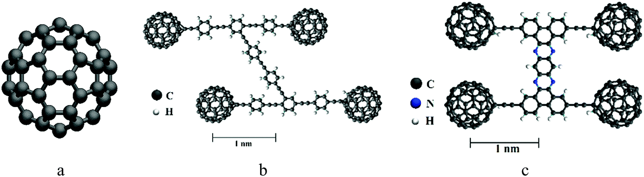 | ||
| Fig. 1 Schematic views of (a) C60, (b) the nanocar, and (c) the nanotruck. C60 is made up of only carbon atoms, the nanocar is made up of carbon and hydrogen atoms, and the nanotruck is made of carbon, nitrogen and hydrogen atoms. | ||
2. Methodology
To attain a clear understanding of the dynamic behavior of nanocars on stepped substrates, we employed a sequential strategy that involved: studying the motion of C60, simulating the nanocar and nanotruck motion on a flat substrate, and investigating their motion on a stepped substrate in different situations. Table 1 demonstrates the different components of the present study.| Section 3 | C60 motion | 3.1. Study of the potential energy surfaces of C60 on a stepped substrate. |
| 3.2. Study of the motion of C60 on a stepped substrate using MD. | ||
| Section 4 | Nanocars on flat substrate | 4.1. Study of the motion of nanocars on a flat substrate. |
| 4.2. Comparison of simulated and experimental results. | ||
| Section 5 | Nanocars on stepped substrate | 5. Investigation of the motion of nanocars on a stepped substrate. |
Since both the nanocar and nanotruck have fullerene wheels, the potential energy of C60 in the vicinity of a single-layer step edge is investigated in the first part of Section 3. As shown in Fig. 2a and b, C60 was placed at the top and bottom sides of a single-layer step, and its potential energy was calculated at different locations. Subsequently, in Section 3.2, the motion of C60 is studied at different temperatures using all-atom classical MD.
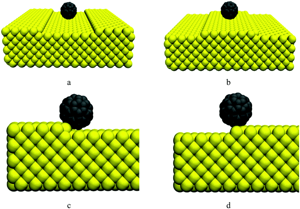 | ||
| Fig. 2 (a) Relative position of C60 on the down side of the single-layer step. (b) C60 on the top side of the single-layer step. (c) C60 near the edge on the bottom side of the step is attracted to the gold atoms at both the bottom and side. (d) C60 near the edge on the top side of the step is attracted to gold atoms mostly from one side. | ||
Next, in Section 4.1, nanocar motion is studied using MD. In Section 4.2, the results are compared to available experimental observations and other theoretical investigations in this field. The motions of C60 and the nanocar and nanotruck are also compared to each other in Section 4.1.
In Section 5, the motions of the nanocar and nanotruck are simulated at both the top and bottom sides of the step. The effects of the step edge on their motion are discussed by comparing the results of this section with the outcomes reported in Section 4.
To compare results from different sections, the simulation setup and parameters where the same where possible. The simulation setup used in each section is explained explicitly in that section.
3. C60 motion
3.1 Potential energy of C60
The potential energy of C60 on a gold substrate is studied in this section. The considered substrate is a surface including a single-layer step. It should be noted that in the rest of this paper, references to the potential energy of C60 indicate the potential energy resulting from the interaction between the carbon atoms of C60 and the gold atoms of the substrate; the internal potential energy among the carbon atoms of C60 is not taken into account. Fullerene is considered as a rigid molecule in the calculation of potential energy. Thus, the potential energy among carbon atoms is constant and does not need to be computed here.As shown in Fig. 2b, fullerene was placed on the top of the step. Pishkenari et al. reported that the potential energy of C60 on a gold substrate depends on its orientation.31 They mentioned that the most stable orientation of C60 is a hexa-down orientation in which C60 is resting on one of its hexagonal faces. We calculated the potential energy of C60 resting on a hexagon face (keeping its orientation intact) and moving it around the edge.
The interaction between carbon and gold atoms was modeled by the 6-12 Lennard-Jones potential:
 | (1) |
The potential energy of C60 near a step is illustrated in Fig. 3. As shown in this figure, the variation in C60 potential energy when passing a step is much higher than when it is sliding on a flat surface. When C60 is on the top side of the step and is approaching the edge, the potential energy increases significantly. After passing the edge, when C60 is on the down side of the step, its potential energy decreases severely. Moving further from the edge, the C60 potential energy increases and becomes similar to that for the case where C60 is moving on a flat surface. As shown in Fig. 3c, the potential energy is minimized when C60 is near the edge on the down side of the step. As shown in Fig. 2c, in this position, C60 is attracted to the gold atoms from both its bottom and side. Thus, C60 is highly stable in this position, and its potential energy is minimized. In contrast, when C60 is near the edge on the top of the step (Fig. 2d), it is primarily attracted to gold atoms from one side; thus, C60 in this position is completely unstable, and its potential energy is relatively high.
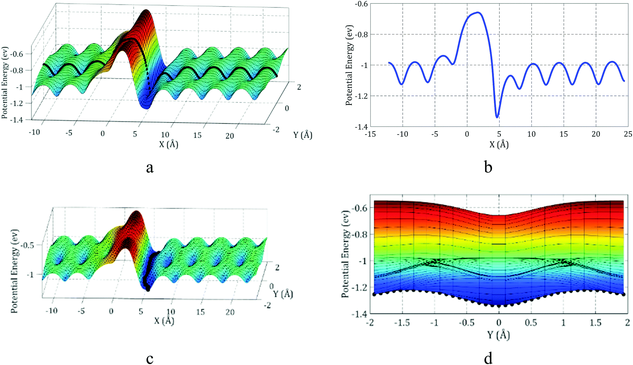 | ||
| Fig. 3 (a) Potential energy of C60 in vicinity of the step edge. The path line Y = 0 is highlighted with black dots. (b) Potential energy of C60 while moving over the edge on the line Y = 0. (c) The minimum energy of C60 occurs when C60 is on the bottom side of the step and attached to the edge. (d) Minimum potential energy of C60 around the edge from different angles of view. | ||
C60 has been reported to have diffusive motion on flat gold substrates.31 Considering this fact and the results illustrated in Fig. 3, we can expect that when C60 is placed on the down side of the step (Fig. 2a), it will approach and eventually attach to the step edge. Afterward, C60 might not have sufficient energy to detach from the edge and will therefore move along the edge. If C60 is placed on the top of the step (Fig. 2b), it will likely not be able to approach or pass the edge because of the energy barrier near the edge; consequently, it will remain on the top side of the step. However, at high temperatures, C60 might have sufficient energy to jump off the edge.
The results obtained by Pishkenari et al. can help us better understand the effect of temperature on the motion of C60 near the edge. The potential energy of C60 when passing the edge on the Y = 0 line was computed and is shown in Fig. 3b. The Y = 0 line is specified in Fig. 3a. The average and maximum potential energies of C60 while moving on the flat substrate at different temperatures were computed using MD and are shown in Fig. 4.
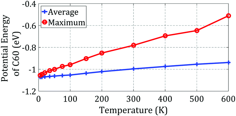 | ||
| Fig. 4 The average and maximum potential energies of C60 at different temperatures on a gold substrate. | ||
As shown in Fig. 3b, C60 must reach an energy of −0.65 eV to pass the edge and go from the top side of the step to the down side. As shown in Fig. 4, C60 can only reach this level of energy at temperatures of 500 K and higher. Thus, we predict that at 500 K and higher temperatures, C60 will have sufficient energy to overcome the high energy barrier and travel to the down side of the step. In contrast, at lower temperatures, it will not be able to pass the edge and will remain on the top side of the step.
As demonstrated in Fig. 3b, when C60 is on the down side of the step, it needs at least 0.27 eV of energy to detach from the step. Considering the results presented in Fig. 4, at temperatures of 400 K and higher, C60 has sufficient energy to make the jump. Thus, we can predict that C60 will detach from the edge and move on the substrate at 400 K and higher temperatures. However, at lower temperatures, it will stick to the edge and only move along the edge. Thus, we can use a stepped surface to control the diffusive motion of C60 and direct its motion along the desired path. In the following sections, we study the potential energy of C60 during motion along the edge.
The best path of C60 motion along the edge is highlighted in Fig. 3c. Herein, the “best path” means the path in which the local potential energy of C60 is minimized, making C60 most stable. As depicted in Fig. 3d, to move along the edge, C60 should be able to perform a powerful jump to overcome an energy barrier of 0.12 eV. Regarding the results presented in Fig. 4, C60 has enough energy to move along the edge at temperatures of 150 K and higher. Pishkenrai et al. predicted that C60 can move on a flat gold substrate at 35 K and higher temperatures.31 This confirms that a stepped substrate will affect the motion of C60 along the edge and reduce the mobility of C60 when it is on the down side of the step. Analyzing the C60 potential energy will not give us more details about its motion near the edge. MD should be used to attain more comprehensive information about the motion of C60 on a stepped substrate.
3.2. Molecular dynamics simulations of C60
The motion of C60 near a step was simulated using classical MD. To investigate the effect of temperature on C60 motion, we performed different simulations at temperatures in the range of 100 to 600 K. Two separate sets of simulations were performed to study the motion of C60 on the top and down sides of the step. Therefore, two different substrate shapes were considered, as shown in Fig. 2. In both cases, the size of the gold substrate was about 57 Å × 57 Å × 12 Å with a single-layer step in the middle, and the width of the step was approximately 20 Å. The gold lattice constant was set to 4.078 Å.43 The normal direction of the surface was set to (001) with respect to a FCC crystalline structure.The lowest layer of gold atoms was set to be rigid. The boundary condition in the horizontal direction was periodic; thus, the substrate size was practically infinite.
The EAM potential was used to simulate the interaction between gold atoms in the substrate.44–46 This potential was developed based on density functional theory and is one the most accurate potentials available for simulating Au and other FCC metals.32,44,47 This potential was reported to accurately simulate the vacancies and disorder in Au substrates,44 and the dislocation structures predicted by this potential are similar to experimental observations.48
The interaction between carbon atoms in C60 was simulated by the AIREBO potential with consideration of both the Lennard-Jones and torsion terms.49,50 As mentioned before, the Au–C interaction was simulated using the Lennard-Jones 6-12 potential (eqn (1)).
To regulate the temperature, two individual Nose–Hoover thermostats were applied to C60 and the substrate.51,52 All simulations were conducted using the LAMMPS package,53 and the results were visualized by VMD Software.54 Simulations were performed for 8 ns with a step size of 1 fs. To increase the modeling accuracy, each simulation was repeated six times.
To better understand the effect of a step on the motion of C60, we also simulated the motion of C60 on a flat substrate under the same conditions. This allowed us compare the motion of C60 in the vicinity of a step edge and on a flat substrate.
The trajectories of C60 during the simulations on flat and stepped substrates are plotted in Fig. 5 for different temperatures.
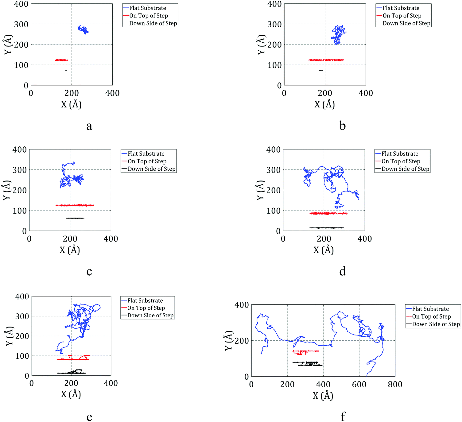 | ||
| Fig. 5 Trajectories of C60 on a gold substrate at (a) 150 K, (b) 200 K, (c) 300 K, (d) 400 K, (e) 500 K, and (f) 600 K. The blue, red, and black lines show the trajectories of C60 on a flat substrate, on the top side of the step, and on the down side of the step, respectively. | ||
As shown in Fig. 5a, C60 can clearly move on the flat surface at 150 K. When C60 is on the top side of the step, its motion is restricted in one direction, while it can move in the other direction as well as on the flat surface. However, when C60 is on the down side of the step, its mobility is affected by the edge.
C60 cannot move in the direction perpendicular to the edge on the down side of the step at 150 K and has a very limited range of motion along the edge. In general, we can report that C60 cannot move when it is on the down side of the step at 150 K.
C60 can move along the edge at 200 K, as depicted in Fig. 5b. However, when it is on the down side of the step, its range of motion is not significant. When it is on the top side of the step, the mobility of C60 along the edge is similar to when it is on the flat substrate. Fig. 5b clearly shows that C60 has a greater range of motion when it is on the top side of the step compared to when it is on the down side of the step.
The trajectories of C60 at different locations at 300 K are illustrated in Fig. 5c. The behavior of C60 at 300 K is similar to that observed at 200 K. At 300 K, C60 has a greater range of motion along the edge when it is on the top side compared to when it is on the down side, and the range of motion for C60 on the top side is similar to that of C60 on the flat substrate.
Pishkenari et al. reported that the range of motion of C60 on a flat surface increases with temperature, which agrees with Fig. 5a–f. However, at 400 K, the range of motion of C60 on the top side of the step is lower than that of C60 on the flat substrate. At this temperature, the mobility of C60 on the top side of the step is relatively lower than its mobility on the flat surface.
By looking closer at the trajectory of C60 at 400 K on the down side of the step, we find that C60 detached from the edge and then reattached to the edge. Thus, at this temperature, C60 has enough energy to detach from the edge, enhancing the range of motion of C60 while it is on the down side of the step. However, its mobility on the down side of the step is still lower than its mobility on the top side.
As illustrated in Fig. 5e, a significant change in the motion regime of C60 on the top side of the step is observed at temperatures of 500 K and higher. At these temperatures, C60 has enough energy to jump over the edge and go to the down side of the step. In other words, the motion of C60 on the top side converts to motion on the down side after a relatively short time. Thus, it is not practical to compare the trajectories of C60 on the top and down sides of the step at these temperatures. As shown in Fig. 5e, C60 clearly detached from the edge several times during the simulation at 500 K.
The motion regime of C60 at 600 K is expected to be similar to that at 500 K; however, as shown in Fig. 5f, the mobility of C60 on the down side of the step was unexpectedly lower than its mobility at 500 K. Another limitation is apparent during the simulation at 600 K. At this temperature, the edge shape does not remain uniform. As shown in Fig. 6a, some atoms of the edge jump from their initial location, creating irregularities that prevent the free motion of C60 along the edge. When C60 reaches this point, it sticks into the dislocation and barely moves. At some times, C60 is able to escape from the dislocation. However, due to the periodic boundary condition considered in the simulations, after escaping, C60 sticks in the next created dislocation. Thus, when one atom from the edge jumps from its initial location, it can severely affect the motion of C60 on the down side of the step.
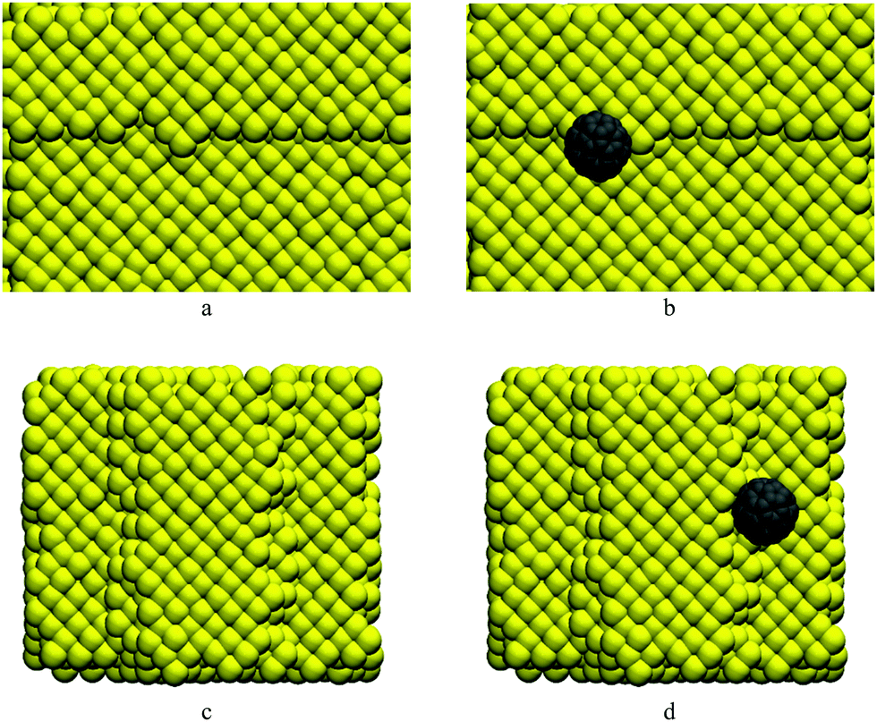 | ||
| Fig. 6 (a) Disarrangement of atoms in the single-layer step structure at 600 K. (b) C60 stuck in the deformed location. (c) Deformed structure of a two-layer step at 600 K. There are many irregularities in the step structure. (d) C60 stuck in the dislocated points. | ||
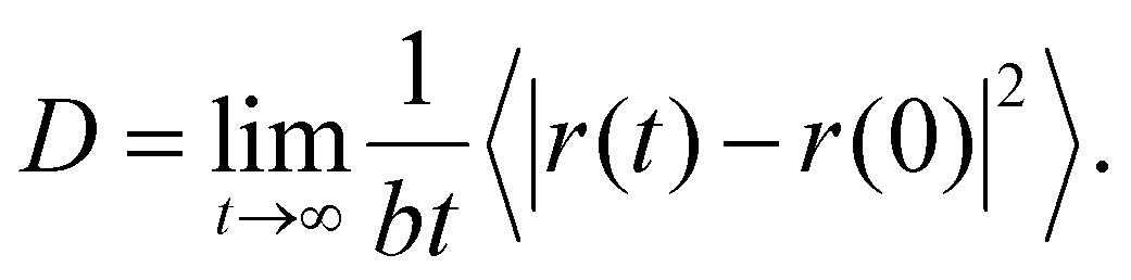
As shown in Fig. 5, C60 has diffusive motion on the flat and stepped substrates. The mean square displacement (MSD) is a helpful parameter to describe the diffusive motion of a particle. Using eqn (2), we can calculate the MSD of C60 motion:55
| MSD(t) = 〈|r(t) − r(0)|2〉, | (2) |
![[thin space (1/6-em)]](https://www.rsc.org/images/entities/char_2009.gif) 〉 represents the average over all simulations performed under specific conditions.
〉 represents the average over all simulations performed under specific conditions.
The diffusion coefficient D, which is one of the best parameters to describe diffusive motion, is derived from MSD, as shown in eqn (3):
 | (3) |
 | ||
| Fig. 7 Diffusion coefficient of C60 under different conditions and temperatures. C60 motion on the top side of the step is similar to its motion on the flat substrate, but the range of C60 motion is very limited when it is on the down side of the step. | ||
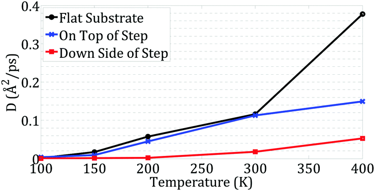
As plotted in Fig. 7, at temperatures less than 200 K, C60 has very limited and short-range motion on the down side of the step, whereas it has considerable motion when on the top side of the step or on a flat substrate.
At temperatures of 300 K and lower, the C60 diffusion coefficients are similar for C60 on a flat substrate and on the top side of the step. This shows that the step did not restrict the C60 motion along the edge; it only limited its motion perpendicular to the edge. However, C60 on the down side of the step is much less mobile than in the two other situations. It is clear that the edge has a significant effect on C60 motion along the edge and reduces its mobility in this situation.
At 400 K, the mobility of C60 considerably increases on the flat substrate. However, the increase in mobility of C60 on the top side of the step is not as large as that of C60 on the flat substrate. In fact, at 400 K, the step also affects the motion of C60 along the edge. The limited space on the top side of the step restricts its range of motion along the edge. As depicted in Fig. 7, this phenomenon was not observed at temperatures of 300 K and lower.
As plotted in Fig. 5e and f, at 500 K and higher temperatures, C60 jumps off the edge and does not remain on the top side of the step. Thus, it is not practical to study the motion of C60 on the top side of the step at high temperatures using MD simulations.
We observed that C60 exhibits very fast motion with a significant motion range at 500 K and higher temperatures on the flat substrate. This may have some interesting applications if we can make its motion directional. However, as we saw before, a single-layer step cannot hold C60, and it may jump off the edge and travel to the down side. To guide the motion of C60 at high temperatures, we studied its motion on the top side of a two-layer step. The simulations were performed under the same conditions as above, and the trajectories of C60 during simulations at 500 K and 600 K are plotted in Fig. 8.
 | ||
| Fig. 8 Trajectories of C60 on the top side of a two-layer step during simulations at 500 K and 600 K. C60 stayed on the top side at 500 K but had sufficient energy to jump off the edge at 600 K. | ||
As shown in Fig. 8, unlike for the single-layer step, C60 remains on the top side of the two-layer step at 500 K. However, the range of motion of C60 at 600 K is unexpectedly low; it seems that C60 has a very limited range of motion on the top side of the two-layer step.
To understand the lower mobility of C60 at 600 K and on the top side of a two-layer step, we need to inspect the structure of the step during simulation. As shown in Fig. 6c, at 600 K, the step experiences severe disorder and cannot preserve its initial structure. In addition, in some places, the two-layer step is converted into two distinct single-layer steps. Thus, at this temperature, the edge cannot retain C60 on the top side. When C60 jumps off the edge to the down side it sticks to the edge at dislocations. This sticking of C60 at messy areas on the edge is the main reason for the decrease in the motion range of C60 at 600 K on the top side of the two-layer step. A snapshot of C60 during the simulation is shown in Fig. 6d.
4. Nanocars on flat substrate
4.1. Nanocar motion on a flat substrate
Based on the results obtained from the simulations of C60 motion, we can present a more detailed analysis of nanocar motion. In this section, we investigate the motion of a nanocar and nanotruck on flat gold substrates at different temperatures.Nanocar and nanotruck motion on a gold substrate was also simulated using classical MD. Because of the larger sizes of the nanocar and nanotruck, a larger substrate was considered. The gold substrate had a size of about 80 Å × 80 Å × 12 Å with a single-layer step in the middle. The lattice constant, crystalline direction and boundary condition were the same as before.
As in the previous section, we employed two individual Nose–Hoover thermostats on the nanocar and the substrate to set the temperatures. Molecular mechanics were used to model the nanocar and nanotruck. Harmonic style was considered for bond and angle terms, as presented in eqn (4) and (5):56
| Ebond = Kb(r − r0)2 | (4) |
| Eangle = Ka(θ − θ0)2, | (5) |
 | (6) |
| Angles parameters | Bonds parameters | Dihedrals parameters | ||||||
|---|---|---|---|---|---|---|---|---|
| K a (eV rad−2) | θ 0 | Description | K b (eV Å−2) | r 0 (Å) | Description | K d1 (eV) | K d2 (eV) | Description |
| 1.46619 | π | C2 C2 CA | 48.6652 | 1.212 | C2 C2 | 0 | 0.0000434 | CA-C2-C2-CA & C2-C2-CA-CA |
| 1.34141 | 2π/3 | C2 CA CA | 30.8837 | 1.313 | C2 CA | 0 | 0.650451 | C2-C2-CA-CA & C2-CA-CA H & H-CA-CA-N |
| 1.34141 | 2π/3 | CA CA CA | 25.1593 | 1.392 | CA CA | −0.0403 | 0.208144 | CA-CA-CA-CA |
| 1.12304 | 2π/3 | CA CA H | 14.35 | 1.101 | CA H | 0 | 0.234379 | CA-CA-CA-H |
| 1.34141 | 2π/3 | CA CA N | 34.596 | 1.260 | CA N | 0 | 0.390271 | H-CA-CA-H |
| 1.34141 | 0.638π | CA NA CA | 0 | 0.433634 | N-CA-CA-N & CA-CA-N-CA | |||
| 0.0433 | 0.650451 | CA-CA-CA-N | ||||||
To conduct more accurate simulations, two different carbon types were considered in the simulations of the nanocar and nanotruck. “CA” carbon atoms have sp2 or sp3 hybridization, and “C2” carbon atoms have sp hybridization.
We simulated the motion of the nanocar and nanotruck on a stepped substrate under null conditions. As no electric field was considered in the simulations, we did not consider charge transfer between the gold substrate and the nanotruck or nanocar. Since the gold substrate is electrically neutral, the electric charge of atoms in these molecular machines has no major effect on their motion.
The Lennard-Jones 6-12 potential was used to model the van der Waals interactions of C–Au, H–Au and N–Au. Both types of carbon atoms were considered to have the same interaction with gold atoms. The Lennard-Jones 6-12 potential is presented in eqn (1), and its parameters are listed in Table 3.42
| ε (eV) | σ (Å) | Description |
|---|---|---|
| 0.01273 | 2.994 | C–Au |
| 0.01315 | 2.611 | H–Au |
| 0.01423 | 2.886 | N–Au |
| 0.00190 | 3.460 | C–C |
| 0.00230 | 3.244 | N–N |
| 0.00204 | 2.673 | H–H |
| 0.00213 | 3.350 | C–N |
| 0.00197 | 3.647 | C–H |
| 0.00220 | 2.958 | N–H |
The trajectories of the nanotruck and nanocar on the flat substrate during the simulations are plotted in Fig. 9.
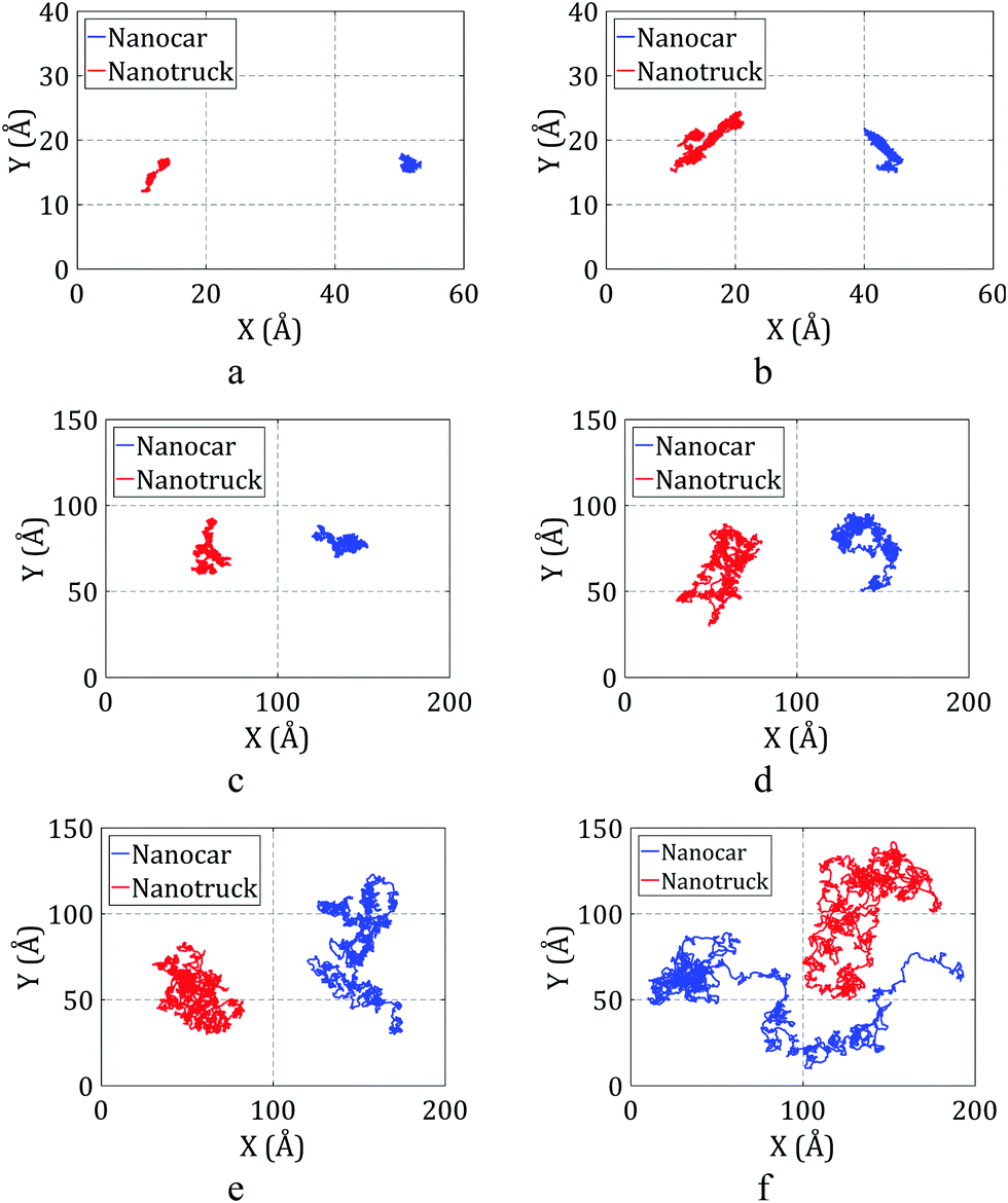 | ||
| Fig. 9 Trajectories of the nanocar and nanotruck on the flat substrate during simulations at (a) 150 K, (b) 200 K, (c) 300 K, (d) 400 K, (e) 500 K, and (f) 600 K. | ||
As depicted in Fig. 9a and b, the nanocar and nanotruck can barely move on the substrate at temperatures of 200 K and lower. At temperatures higher than 200 K, both of them start to move, and they have free motion on the gold substrate at temperatures of 400 K and higher. We used the diffusion coefficient to better describe the motion of the nanocar and nanotruck on the flat substrate. The diffusion coefficients were calculated for both molecular machines at different temperatures and are plotted in Fig. 10.
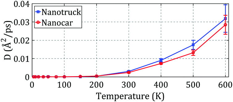 | ||
| Fig. 10 Diffusion coefficients of the nanocar and nanotruck on the flat substrate at different temperatures. The range of motion of the nanotruck is greater than that of the nanocar at every temperature. | ||
Considering the results depicted in Fig. 10, we can conclude that the nanotruck is more agile than the nanocar. The nanocar has a heavier chassis compared to the nanotruck, and the chassis of the nanocar is more flexible than that of the nanotruck. The flexibility of the nanocar chassis dissipates some of its energy and dampens its motion; thus, the flexibility of the nanocar chassis reduces its motion speed and range. As a result, we can deduce that the lighter and stiffer chassis of the nanotruck lets it move faster and travel over longer distances.
By comparing the diffusivity and trajectory of the nanotruck and nanocar with those of C60, it is obvious that both molecular machines are extremely slower and have relatively limited ranges of motion. C60 molecule, as the wheel of the nanotruck and nanocar, has vibrational motion. The effect of one wheel on the net motion of nanocar (or nanotruck) chassis is cancelled by the vibrational motions of the other wheels. As a result, the speed and motion range of the nanocar and nanotruck are much lower than those of C60. However, since the interaction of both molecular machines with the gold substrate occurs through their wheels, we can use the results obtained for the motion of C60 to predict the motion regime of the nanocar or nanotruck.
4.2 Experimental observations
The experimental investigation of nanocars is expensive and time consuming; as a result, there are few experimental studies available on nanocar motion. One of the most important studies was done by Zhang et al.16 They investigated free motion of some types of nanocars under ultra-high vacuum on a flat gold substrate.Comparisons of simulations and experimental observations are mostly qualitative due to the serious limitation in available experimental studies. In the images published by Zhang et al.,16 only the wheels are visible as bright points, while the chassis is nearly invisible. Thus, it is impractical to obtain detailed information about the behavior of the chassis during motion.
With STM, only a few images can be taken in a minute; thus, comprehensive information on the fast and agile motion of nanocars may not be revealed by STM imaging.
The process used to fabricate nanocars results in multiple nanocars present on the substrate. Separating a single nanocar makes an experiment even more cumbersome. Thus, in experiments, many nanocars are visible on the substrate. Eventually, the nanocars attach to each other while moving randomly on the substrate, resulting in a colony of nanocars. The attachment of a nanocars to a colony severely affects and restricts nanocar motion. This reduces the chance of setting up a successful long-term experimental study.
In this study, we aimed to validate our simulation results by comparing them with experimental observations. Good agreement between simulation results and experimental observations would let us go further to obtain more detailed information through extended simulations.
Zhang et al. observed that a nanocar remained motionless at temperatures lower than 200 °C and began to move on the flat substrate at a temperature of around 200 °C. They reported that nanocar motion was a combination of rotation and translation at 200 °C. At higher temperatures (e.g., 300 °C), STM imaging did not produce usable results because of the rapid motion of the nanocars.
The simulation results presented in Section 4.1 show that the nanocar has no noticeable motion at temperatures of 400 K and lower. At 500 K (227 °C), the nanocar has significant motion and can freely move and rotate on the substrate. At 600 K (327 °C), it travels very long distances during the simulation time.
Comparing the simulation results with experimental observations indicates acceptable agreement between simulation and experiment. Thus, we can be confident about the simulation results and obtain more detailed information about nanocar motion under different conditions using theoretical studies.
5. Nanocars on stepped substrate
In this section, we study nanocar and nanotruck motion on the top and down sides of the step at different temperatures lower than 600 K. A single-layer step was considered, and the other simulation conditions and parameters were the same as above. The trajectories of the nanocar and nanotruck on the top side of a single-layer step are plotted in Fig. 11.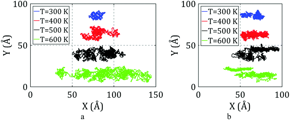 | ||
| Fig. 11 Simulated trajectories of the nanocar and nanotruck on the top side of a single-layer step at different temperatures. (a) Trajectories of the nanotruck. It stays on the top side of the step, even at 600 K. (b) Trajectories of the nanocar. It has a limited range of motion relative to the nanotruck. One of the nanocar wheels jumps off the step at temperatures of 500 K and 600 K, reducing its mobility. | ||
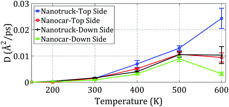
As presented in Section 3.2, C60 cannot pass the edge and remains on the top side of the step at temperatures of 400 K and lower. Thus, the nanocar and nanotruck were expected to remain on the top side of the step and not pass the edge. The edge limits the motion of both molecular machines in the direction perpendicular to the edge and forces them to move alongside the edge. To investigate the effect of the edge on nanocar and nanotruck motion, the diffusion coefficients of the nanocar and nanotruck for motion along the edge were computed at different temperatures (Fig. 12).
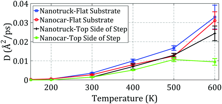 | ||
| Fig. 12 Diffusion coefficients of the nanocar and nanotruck on the flat substrate and top side of the step at different temperatures. | ||
As depicted in Fig. 12, the diffusion coefficients of the nanocar and nanotruck during motion on the top side of the step were less than those of the nanocar and nanotruck on the flat substrate. It can be concluded that the edge limits the motion of the nanocar and nanotruck while they are on the top side of the step. However, the edge has no significant effect on the motion of the nanocar and nanotruck along the edge.
The simulation of C60 motion on the top side of the step demonstrates that at 500 K, C60 does not remain on the top side of the step and can jump over the edge and move to the down side of the step. The effect of this phenomenon on the motion of the nanocar and nanotruck is investigated in the next section.
As mentioned above, the flexibility of the nanocar chassis lets the wheels have some free motion relative to the whole nanocar. As expected, one of the nanocar wheels jumped off the step and stuck to the edge, severely limiting the mobility of the nanocar. A snapshot of the nanocar in this situation is presented in Fig. 13a. Since the nanotruck has more rigid chassis, a different result was observed. When investigating nanotruck motion at the same temperature, we found that the nanotruck remained on the top side of the step during the entire simulation time. The simulation was repeated five times, and the same result was obtained. The rigidity of the nanotruck chassis did not allow the wheels to jump off the edge, and the entire nanotruck remained on the top side. As expected, the motion of the nanotruck at 500 K was faster than the motion at 400 K, and the diffusion coefficient was higher at 500 K.
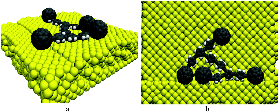 | ||
| Fig. 13 (a) One of the nanocar wheels jumped off the step edge during the simulation at 500 K. This event significantly reduced the motion range of the nanocar. (b) Due to the flexibility of the nanocar chassis, three wheels of the nanocar attached to the step edge at some times. This is the main reason for the reduced mobility of the nanocar relative to the nanotruck at high temperatures. | ||
Next, the effect of a single-layer step on the motion of the nanocar and nanotruck on the down side of the step was investigated. The diffusion coefficients for the motions of both molecular machines were computed and are plotted in Fig. 14. To better understand the effect of the edge on the motion of the nanocar and nanotruck in this situation, the diffusion coefficients of both molecular machines on the top side of the step are also plotted in Fig. 14.
 | ||
| Fig. 14 Diffusion coefficients of the nanocar and nanotruck on the top and down sides of the step at different temperatures. | ||
As depicted in Fig. 14, the edge has a severe effect on nanocar and nanotruck motion when they are on the down side of the step. During the simulations, the nanocar and nanotruck barely moved, particularly at low temperatures. This is primarily attributed to the attachment of the wheels to the edge. When investigating the motion of C60, we observed that its motion alongside of the edge is restricted by the edge because C60 must overcome the high energy barrier to move along the edge. Thus, the nanocar and nanotruck motion along the edge is restricted by the attachment of their wheels to the edge.
Considering the results shown in Fig. 14, the diffusion coefficient of the nanocar is less than expected compared to the nanocar, especially at high temperatures. By examining the nanocar during the simulations, we observe that the nanocar experiences major deformation during motion due to the flexibility of the nanocar chassis. The deformation of the nanocar chassis causes three wheels attach to the edge at the same time, further reducing the mobility of the nanocar. Some snapshots from the nanocar simulation are shown in Fig. 13b. Once again, the flexibility of the nanocar restricts the nanocar motion.
Due to the dislocation of atoms in the edge at temperatures of 600 K and higher, the simulations of the nanocar and nanotruck at this temperature do not provide any additional information.
6. Conclusion
In this paper, we studied the motion of C60, a nanocar, and a nanotruck from 100 K to 600 K on a flat gold substrate and in the presence of a step. The main objective was to investigate the effect of the step on the motion of these molecules. All-atom MD simulations were used to analyze the potential energy of C60 around the edge. We observed that C60 can freely move on the flat substrate in the studied temperature range, whereas the nanocar and nanotruck are almost immobile at temperatures below 200 K. The nanocar and nanotruck both show short-range fluctuations at temperatures between 200 K and 400 K, and they can freely move and rotate on the flat substrate at temperatures higher than 400 K. The motion range of C60 is significantly higher than those of the nanocar and nanotruck at the same temperature. In addition, due to its heavier and more flexible chassis, the nanocar has a lower range of motion than the nanotruck.When C60 gets close to the step but is still on the top side of the step, its potential energy increases, and it becomes unstable. C60 tends to recede from the edge in this situation. At temperatures of 400 K and lower, C60 does not have enough energy to jump off the edge and travel to the down side of the step. In contrast, at temperatures of 500 K and higher, C60 can jump over the edge.
If C60 approaches the step edge while it is on the down side of the step, it is attracted to the step edge and attaches to it. At temperatures lower than 400 K, C60 cannot detach from the edge. In this case, the motion of C60 is only alongside the edge; it has no motion perpendicular to the edge. The motion range and speed of C60 along the edge in this situation is less than when C60 freely moves on the flat substrate. However, the diffusive motion of C60 along the edge on the top side of the step is similar to its motion on the flat substrate. Due to the deformation of the step edge, the simulation of C60 motion on the down side of the step may not be practical at 600 K.
The simulations of nanocar and nanotruck motion on a stepped substrate demonstrate that their motion alongside the edge on the top side of the step is similar to their motion on the flat substrate. The step has a minor effect on their motion in this condition. Due to the flexible chassis of the nanocar, one of its wheels jump off the edge at temperatures of 500 K and higher, which significantly restricts its motion. Thus, the simulation of nanocar motion on the top side of the step was not successful at temperatures of 500 K and higher. The nanotruck has a relatively rigid chassis that prevents the free individual motion of the wheels. As a result, the nanotruck stays on the top side of the step, even at 600 K. When the nanocar and nanotruck are on the down side of the step, they are severely affected by the edge, and their ranges of motion are very limited. The mobility of the nanocar is even less than that of the nanotruck in this situation. The flexible chassis of the nanocar makes it possible for three wheels of the nanocar to attach to the step edge simultaneously, which considerably restricts its motion.
In conclusion, we demonstrated that a stepped substrate can limit the motion of C60, the nanocar, and the nanotruck in one direction and provide a firm pathway for their motion. Taking advantage of this phenomenon, we can make complicated routes for the transport of these molecular machines, particularly when they are on the top side of the stepped substrate.
Conflicts of interest
There are no conflicts to declare.References
- P. Samorì, Scanning probe microscopies beyond imaging: manipulation of molecules and nanostructures, John Wiley & Sons, 2006 Search PubMed.
- G. Vives and J. M. Tour, Synthesis of Single-Molecule nanocars, Acc. Chem. Res., 2009, 42(3), 473–487 CrossRef CAS PubMed.
- K. Kinbara and T. Aida, Toward intelligent molecular machines: directed motions of biological and artificial molecules and assemblies, Chem. Rev., 2005, 105(4), 1377–1400 CrossRef CAS PubMed.
- V. L. Popov, Nanomachines: methods to induce a directed motion at nanoscale, Phys. Rev. E: Stat., Nonlinear, Soft Matter Phys., 2003, 68(2), 026608 CrossRef CAS PubMed.
- T. Sasaki, J. F. Morin, M. Lu and J. M. Tour, Synthesis of a single-molecule nanotruck, Tetrahedron Lett., 2007, 48(33), 5817–5820 CrossRef CAS.
- T. Sasaki and J. M. Tour, Synthesis of a new photoactive nanovehicle: a nanoworm, Org. Lett., 2008, 10(5), 897–900 CrossRef CAS PubMed.
- Y. Shirai, A. J. Osgood, Y. Zhao, Y. Yao, L. Saudan, H. Yang, C. Yu-Hung, L. B. Alemany, T. Sasaki, J. F. Morin, J. M. Guerrero, K. F. Kelly and J. M. Tour, Surface-rolling molecules, J. Am. Chem. Soc., 2006, 128(14), 4854–4864 CrossRef CAS PubMed.
- Y. Shirai, J. F. Morin, T. Sasaki, J. M. Guerrero and J. M. Tour, Recent progress on nanovehicles, Chem. Soc. Rev., 2006, 35(11), 1043–1055 RSC.
- P.-L. E. Chu, L.-Y. Wang, S. Khatua, A. B. Kolomeisky, S. Link and J. M. Tour, Synthesis and single-molecule imaging of highly mobile adamantane-wheeled nanocars, ACS Nano, 2012, 7(1), 35–41 CrossRef PubMed.
- T. Sasaki, A. J. Osgood, J. L. Kiappes, K. F. Kelly and J. M. Tour, Synthesis of a porphyrin-fullerene pinwheel, Org. Lett., 2008, 10(7), 1377–1380 CrossRef CAS PubMed.
- T. Sasaki and J. M. Tour, Synthesis of a dipolar nanocar, Tetrahedron Lett., 2007, 48(33), 5821–5824 CrossRef CAS.
- J. F. Morin, T. Sasaki, Y. Shirai, J. M. Guerrero and J. M. Tour, Synthetic routes toward carborane-wheeled nanocars, J. Org. Chem., 2007, 72(25), 9481–9490 CrossRef CAS PubMed.
- T. Sasaki, J. M. Guerrero and J. M. Tour, The assembly line: self-assembling nanocars, Tetrahedron, 2008, 64(36), 8522–8529 CrossRef CAS.
- T. Sasaki, A. J. Osgood, L. B. Alemany, K. F. Kelly and J. M. Tour, Synthesis of a nanocar with an angled chassis. Toward circling movement, Org. Lett., 2008, 10(2), 229–232 CrossRef CAS PubMed.
- G. Vives, J. Kang, K. F. Kelly and J. M. Tour, Molecular machinery: synthesis of a “nanodragster”, Org. Lett., 2009, 11(24), 5602–5605 CrossRef CAS PubMed.
- J. Zhang, A. Osgood, Y. Shirai, J. F. Morin, T. Sasaki, J. M. Tour and K. F. Kelly, Investigating the motion of molecular machines on surfaces by STM: the nanocar and beyond. In Nanotechnology, 2007. IEEE-NANO 2007. 7th IEEE Conference on, 2007.
- Y. Shirai, A. J. Osgood, Y. Zhao, K. F. Kelly and J. M. Tour, Directional control in thermally driven single-molecule nanocars, Nano Lett., 2005, 5(11), 2330–2334 CrossRef CAS PubMed.
- S. Konyukhov, N. Artemov, I. Kaliman, I. Kupchenko, A. Nemukhin and A. Moskovskii, Diffusion of fullerene-based nanocars on the surface of a gold crystal, Moscow Univ. Chem. Bull., 2010, 65(4), 219–220 CrossRef.
- S. S. Konyukhov, I. V. Kupchenko, A. A. Moskovsky, A. V. Nemukhin, A. V. Akimov and A. B. Kolomeisky, Rigid-body molecular dynamics of fullerene-based nanocars on metallic surfaces, J. Chem. Theory Comput., 2010, 6(9), 2581–2590 CrossRef CAS PubMed.
- A. V. Akimov, A. V. Nemukhin, A. A. Moskovsky, A. B. Kolomeisky and J. M. Tour, Molecular dynamics of surface-moving thermally driven nanocars, J. Chem. Theory Comput., 2008, 4(4), 652–656 CrossRef CAS PubMed.
- A. V. Akimov and A. B. Kolomeisky, Unidirectional Rolling Motion of Nanocars Induced by Electric Field, J. Phys. Chem. C, 2012, 116(42), 22595–22601 CAS.
- A. Nemati, H. N. Pishkenari, A. Meghdari and S. Shorabpour, Nanocar & nanotruck motion on gold surface, in Manipulation, Automation and Robotics at Small Scales (MARSS), International Conference on IEEE, 2016 Search PubMed.
- M. Neek-Amal, N. Abedpour, S. N. Rasuli, A. Naji and M. R. Ejtehadi, Diffusive motion of C 60 on a graphene sheet, Phys. Rev. E: Stat., Nonlinear, Soft Matter Phys., 2010, 82(5), 051605 CrossRef CAS PubMed.
- M. Ozmaian, A. Fathizadeh, M. Jalalvand, M. R. Ejtehadi and S. M. V. Allaei, Diffusion and self-assembly of C60 molecules on monolayer graphyne sheets, Sci. Rep., 2016, 6, 21910 CrossRef CAS PubMed.
- A. V. Savin and Y. S. Kivshar, Transport of fullerene molecules along graphene nanoribbons, Sci. Rep., 2012, 2, 1012 CrossRef PubMed.
- M. Jafary-Zadeh, C. Reddy, V. Sorkin and Y.-W. Zhang, Kinetic nanofriction: a mechanism transition from quasi-continuous to ballistic-like Brownian regime, Nanoscale Res. Lett., 2012, 7(1), 1–8 CrossRef PubMed.
- N. Martsinovich and L. Kantorovich, Modelling the manipulation of C60 on the Si(001) surface performed with NC-AFM, Nanotechnology, 2009, 20(13), 135706 CrossRef CAS PubMed.
- R. Pawlak, S. Kawai, S. Fremy, T. Glatzel and E. Meyer, High-resolution imaging of C60 molecules using tuning-fork-based non-contact atomic force microscopy, J. Phys.: Condens. Matter, 2012, 24(8), 084005 CrossRef CAS PubMed.
- G. Teobaldi and F. Zerbetto, C60 on Gold: Adsorption, Motion, and Viscosity, Small, 2007, 3(10), 1694–1698 CrossRef CAS PubMed.
- R. J. Baxter, P. Rudolf, G. Teobaldi and F. Zerbetto, Modelling of the Adsorption of C60 on the Au(110) Surface, ChemPhysChem, 2004, 5(2), 245–248 CrossRef CAS PubMed.
- H. N. Pishkenari, A. Nemati, A. Meghdari and S. Sohrabpour, A close look at the motion of C 60 on gold, Curr. Appl. Phys., 2015, 15(11), 1402–1411 CrossRef.
- H. Hao and D. Lau, Atomistic modeling of metallic thin films by modified embedded atom method, Appl. Surf. Sci., 2017, 422(Supplement C), 1139–1146 CrossRef CAS.
- P. Hecquet, Surface stress stabilizes vicinal surfaces, Surf. Sci., 2004, 561(2), 127–146 CrossRef CAS.
- J. Lecoeur and S. Rousset, Electrochemical behaviour of Au(111) vicinal faces: atomic structure stability of Au(755) and Au(332) surfaces, J. Electroanal. Chem., 2002, 519(1), 18–24 CrossRef CAS.
- M. Moiseeva, E. Pichardo-Pedrero, G. Beltramo, H. Ibach and M. Giesen, Reconstruction on Au(001) vicinal surfaces in UHV and in sulfuric acid solution, Surf. Sci., 2009, 603(4), 670–675 CrossRef CAS.
- V. Repain, J. Berroir, S. Rousset and J. Lecoeur, Reconstruction, step edges and self-organization on the Au(111) surface, Appl. Surf. Sci., 2000, 162, 30–36 CrossRef.
- B. Pieczyrak, A. Trembulowicz, G. Antczak and L. Jurczyszyn, Nature of monovacancies on quasi-hexagonal structure of reconstructed Au(100) surface, Appl. Surf. Sci., 2017, 407, 345–352 CrossRef CAS.
- D. Yuan, Z. Liu and Y. Xu, First-principles investigations of O 2 dissociation on low-coordinated Pd ensembles over stepped Au surfaces, Phys. Lett. A, 2012, 376(45), 3432–3438 CrossRef CAS.
- Z.-F. Wu, Z.-Q. Jiang, Y.-K. Jin, F. Xiong, G.-H. Sun and W.-X. Huang, Oxidation of formic acid on stepped Au(997) surface, Chin. J. Catal., 2016, 37(10), 1738–1746 CrossRef CAS.
- G. Watson, D. Gibbs, D. Zehner, M. Yoon and S. Mochrie, Orientational phase diagram of the stepped Au(001) surface, Surf. Sci., 1998, 407(1–3), 59–72 CrossRef CAS.
- S. Rousset, F. Pourmir, J. Berroir, J. Klein, J. Lecoeur, P. Hecquet and B. Salanon, Self-organization on Au(111) vicinal surfaces and the role of surface stress, Surf. Sci., 1999, 422(1), 33–41 CrossRef CAS.
- H. Heinz, R. Vaia, B. Farmer and R. Naik, Accurate simulation of surfaces and interfaces of face-centered cubic metals using 12-6 and 9-6 Lennard-Jones potentials, J. Phys. Chem. C, 2008, 112(44), 17281–17290 CAS.
- B. N. Dutta and B. Dayal, Lattice Constants and Thermal Expansion of Gold up to 878 °C by X-Ray Method, Phys. Status Solidi B, 1963, 3(3), 473–477 CrossRef CAS.
- M. S. Daw and M. I. Baskes, Embedded-atom method: derivation and application to impurities, surfaces, and other defects in metals, Phys. Rev. B: Condens. Matter Mater. Phys., 1984, 29(12), 6443 CrossRef CAS.
- M. Finnis and J. Sinclair, A simple empirical N-body potential for transition metals, Philos. Mag. A, 1984, 50(1), 45–55 CrossRef CAS.
- S. Foiles, M. Baskes and M. Daw, Embedded-atom-method functions for the fcc metals Cu, Ag, Au, Ni, Pd, Pt, and their alloys, Phys. Rev. B: Condens. Matter Mater. Phys., 1986, 33(12), 7983 CrossRef CAS.
- M. I. Haftel, Surface reconstruction of platinum and gold and the embedded-atom model, Phys. Rev. B: Condens. Matter Mater. Phys., 1993, 48(4), 2611 CrossRef CAS.
- X. Zhou, R. Johnson and H. Wadley, Misfit-energy-increasing dislocations in vapor-deposited CoFe/NiFe multilayers, Phys. Rev. B: Condens. Matter Mater. Phys., 2004, 69(14), 144113 CrossRef.
- D. W. Brenner, O. A. Shenderova, J. A. Harrison, S. J. Stuart, B. Ni and S. B. Sinnott, A second-generation reactive empirical bond order (REBO) potential energy expression for hydrocarbons, J. Phys.: Condens. Matter, 2002, 14(4), 783 CrossRef CAS.
- S. J. Stuart, A. B. Tutein and J. A. Harrison, A reactive potential for hydrocarbons with intermolecular interactions, J. Chem. Phys., 2000, 112(14), 6472–6486 CrossRef CAS.
- W. G. Hoover, Canonical dynamics: equilibrium phase-space distributions, Phys. Rev. A: At., Mol., Opt. Phys., 1985, 31(3), 1695 CrossRef.
- S. Nosé, A unified formulation of the constant temperature molecular dynamics methods, J. Chem. Phys., 1984, 81(1), 511–519 CrossRef.
- S. Plimpton, Fast parallel algorithms for short-range molecular dynamics, J. Comput. Phys., 1995, 117(1), 1–19 CrossRef CAS.
- W. Humphrey, A. Dalke and K. Schulten, VMD: visual molecular dynamics, J. Mol. Graphics, 1996, 14(1), 33–38 CrossRef CAS PubMed.
- H. Qian, M. P. Sheetz and E. L. Elson, Single particle tracking. Analysis of diffusion and flow in two-dimensional systems, Biophys. J., 1991, 60(4), 910 CrossRef CAS PubMed.
- U. Burkert and N. L. Allinger, Molecular mechanics, American Chemical Society, Washington, DC, vol. 177, 1982 Search PubMed.
- E. K. Watkins and W. L. Jorgensen, Perfluoroalkanes: conformational analysis and liquid-state properties from ab initio and Monte Carlo calculations, J. Phys. Chem. A, 2001, 105(16), 4118–4125 CrossRef CAS.
- N. L. Allinger, Conformational analysis. 130. MM2. A hydrocarbon force field utilizing V1 and V2 torsional terms, J. Am. Chem. Soc., 1977, 99(25), 8127–8134 CrossRef CAS.
- N. L. Allinger, K. Chen and J. H. Lii, An improved force field (MM4) for saturated hydrocarbons, J. Comput. Chem., 1996, 17(5–6), 642–668 CrossRef CAS.
- N. L. Allinger, Y. H. Yuh and J. H. Lii, Molecular mechanics. The MM3 force field for hydrocarbons. 1, J. Am. Chem. Soc., 1989, 111(23), 8551–8566 CrossRef CAS.
- J. H. Lii and N. L. Allinger, Molecular mechanics. The MM3 force field for hydrocarbons. 3. The van der Waals' potentials and crystal data for aliphatic and aromatic hydrocarbons, J. Am. Chem. Soc., 1989, 111(23), 8576–8582 CrossRef CAS.
- J. H. Lii and N. L. Allinger, Molecular mechanics. The MM3 force field for hydrocarbons. 2. Vibrational frequencies and thermodynamics, J. Am. Chem. Soc., 1989, 111(23), 8566–8575 CrossRef CAS.
Footnote |
| † Electronic supplementary information (ESI) available. See DOI: 10.1039/c7cp07217a |
| This journal is © the Owner Societies 2018 |