
 Open Access Article
 This Open Access Article is licensed under a
 Creative Commons Attribution 3.0 Unported Licence
Carbon nitrides: synthesis and characterization of a new class of functional materials
T. S.
Miller
a,
A. Belen
Jorge
b,
T. M.
Suter
a,
A.
Sella
a,
F.
Corà
a and
P. F.
McMillan
 *a
*a
aDepartment of Chemistry, Christopher Ingold Building, University College London, 20 Gordon Street, WC1H 0AJ, London, UK. E-mail: p.f.mcmillan@ucl.ac.uk
bMaterials Research Institute, School of Engineering and Materials Science, Queen Mary University of London, Mile End Rd, E1 4NS, London, UK
First published on 30th May 2017
Abstract
Carbon nitride compounds with high N![[thin space (1/6-em)]](https://www.rsc.org/images/entities/char_2009.gif) :C ratios and graphitic to polymeric structures are being investigated as potential next-generation materials for incorporation in devices for energy conversion and storage as well as for optoelectronic and catalysis applications. The materials are built from C- and N-containing heterocycles with heptazine or triazine rings linked via sp2-bonded N atoms (N(C)3 units) or –NH– groups. The electronic, chemical and optical functionalities are determined by the nature of the local to extended structures as well as the chemical composition of the materials. Because of their typically amorphous to nanocrystalline nature and variable composition, significant challenges remain to fully assess and calibrate the structure–functionality relationships among carbon nitride materials. It is also important to devise a useful and consistent approach to naming the different classes of carbon nitride compounds that accurately describes their chemical and structural characteristics related to their functional performance. Here we evaluate the current state of understanding to highlight key issues in these areas and point out new directions in their development as advanced technological materials.
:C ratios and graphitic to polymeric structures are being investigated as potential next-generation materials for incorporation in devices for energy conversion and storage as well as for optoelectronic and catalysis applications. The materials are built from C- and N-containing heterocycles with heptazine or triazine rings linked via sp2-bonded N atoms (N(C)3 units) or –NH– groups. The electronic, chemical and optical functionalities are determined by the nature of the local to extended structures as well as the chemical composition of the materials. Because of their typically amorphous to nanocrystalline nature and variable composition, significant challenges remain to fully assess and calibrate the structure–functionality relationships among carbon nitride materials. It is also important to devise a useful and consistent approach to naming the different classes of carbon nitride compounds that accurately describes their chemical and structural characteristics related to their functional performance. Here we evaluate the current state of understanding to highlight key issues in these areas and point out new directions in their development as advanced technological materials.
 T. S. Miller | Thomas S. Miller currently works as a research associate in the Dept. of Chemistry at UCL. His research interests span from fundamental electrochemistry to materials discovery/characterisation and the development of devices for electrochemical energy storage and generation. He received his PhD from the University of Warwick in 2014, where he studied the electrochemical applications of carbon nanotubes and graphene. In his recent work he has produced new methods for the scalable production of 2D materials and created carbon nitride composites for application in fuel cells, batteries, electrolyzers and supercapacitors. |
 A. Belen Jorge | Ana Belen Jorge graduated in Chemistry in Canary Islands in 2004. She obtained her PhD in Materials Science from the Instituto de Ciencia de Materiales and the Universidad Autonoma de Barcelona in 2009. After some time in industry, she decided to come back to academia in 2011, and moved to London to conduct a postdoc at UCL investigating new graphitic carbon nitrides for energy applications. Currently, she is an academic fellow at the Materials Research Institute, QMUL. Her research focuses in creating new hybrid materials for energy, including oxygen electrocatalysts and photoanodes for photofuel cells and water splitting. |
 T. M. Suter | Theo M. Suter graduated with an MSci in Chemistry with Molecular physics from Imperial College London in 2014. He is now in the final year of his PhD at University College London, where he works on the synthesis, characterisation and functionalisation of layered carbon nitrides. His particular focus is the exfoliation and ion exchange of highly crystalline frameworks. |
 A. Sella | Italian by birth, Andrea Sella studied organometallic chemistry with Robert H. Morris (Toronto) and Malcom L. H. Green (Oxford). His research interests focus on inorganic synthesis in areas ranging from the lanthanides to the allotropes of phosphorus and tin. He is heavily involved in the development of undergraduate practicals that incorporate citizen science and outreach into traditional exercises, to strengthen community and environmental awareness among undergraduates. He is also known as a broadcaster, being a regular contributor to radio and television, such as the recent 74 part series on The Elements on BBC World Service He is known online as @SellaTheChemist. |
 F. Corà | Furio Corà graduated at the University of Torino and received a PhD in Chemistry from the University of Portsmouth. He has been an EPSRC Advanced Research Fellow at the Royal Institution of Great Britain (2001–2006), before moving to UCL where he is Professor of Computational Chemistry. He employs electronic structure calculations to investigate functional, electronic and catalytic properties of crystalline solids. Particular emphasis is given to the integration of computational studies with experimental synthesis and characterisation methods, both as an analytical tool to assist the interpretation of experiment, and predictive to identify significant targets in advance of experiment. |
 P. F. McMillan | Paul F. McMillan is Ramsay Professor of Chemistry at UCL. He obtained his PhD at Arizona State University (1981) and remained there until 2000 when he moved to London to establish research programmes in solid state chemistry and high pressure science. His work on carbon nitrides began in Arizona and extends to developing them for energy applications and as nanomaterials. Other research interests include amorphous materials and high pressure biology/biophysics. He received a Wolfson-Royal Society Research Merit Award (2001–2006), the Solid State Chemistry award in 2003, an EPSRC Senior Research Fellowship (2006–2011) and the Peter Day award in 2011. |
1. Introduction
Carbon nitride solid state compounds are emerging as important materials for energy and sustainability applications ranging from visible-UV light harvesting and photocatalysis,1–5 to fuel cell and electrolyzer catalyst supports,6–8 as redox catalysts,9–12 as well as for other emerging areas.5,13–18 These applications all rely on the unique set of optical, electronic, and chemical properties possessed by the carbon nitrides, combined with their synthesis from readily available precursors, and their resistance to adverse chemical and physical environments. However, further development of these materials requires addressing and resolving fundamental questions concerning their chemical and structural nature in relation to their properties so that they can be designed and optimized for current and future applications. The rate of publication concerning these compounds is accelerating: at the time of writing, Web of Science records approximately 18000 papers with “carbon nitride” or “C3N4” in the title or abstract (Fig. 1). Now is a critical time to assess our current understanding of the physical, chemical and structural properties of these materials in relation to their functionality.
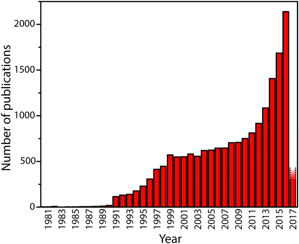 | ||
| Fig. 1 The number of publications containing “carbon nitride” or “g-C3N4” in title or abstract by year until early 2017. The rapid upsurge in activity beginning in 1991 followed the theoretical prediction in 1989 by Cohen and Liu28 that a high density phase containing sp3-bonded C atoms might exist. The recent activity has been promoted by discoveries that indicate the “graphitic” materials might have useful properties for catalysis and energy conversion or storage, as well as other potential applications. | ||
A first issue to be addressed concerns the most appropriate nomenclature used to describe the different classes of carbon nitride materials generated by various chemical and physical routes. It has become increasingly common to refer to them as “g-C3N4”, and we find that the Wikipedia entry for “graphitic carbon nitride” states: “Graphitic carbon nitride (g-C3N4) is a family of compounds with a general formula near to C3N4 and structures based on heptazine units which, depending on reaction conditions, exhibit different degrees of condensation, properties and reactivities”.19 That definition is misleading for a number of reasons. First, most of the materials prepared to date contain not only C and N, but also substantial quantities of H as an essential component of their structures, and these carbon nitride forms are in fact best described as CxNyHz compounds. Next, those materials produced by linked heptazine (tri-s-triazine, C6N7) units the layers are unlikely to be completely condensed “graphitic” structures, but instead form zigzag polymer chains similar to those found in Liebig's melon, with a limiting composition near C2N3H.20–22 Only a very few reports have described structures that form fully condensed layers with C3N4 stoichiometry, but these have been shown to be based on linked triazine (C3N3) rings rather than heptazine units.23,24 Another series of compounds containing planar carbon nitride layers are also formed by polytriazine imide-linked (PTI) units that provide hosts for intercalated ions including Li+, Cl− and Br−, as well as additional H+.25–27 It is interesting to note that the PTI layers have composition C2N3H, equivalent to that of Liebig's melon (Fig. 2).
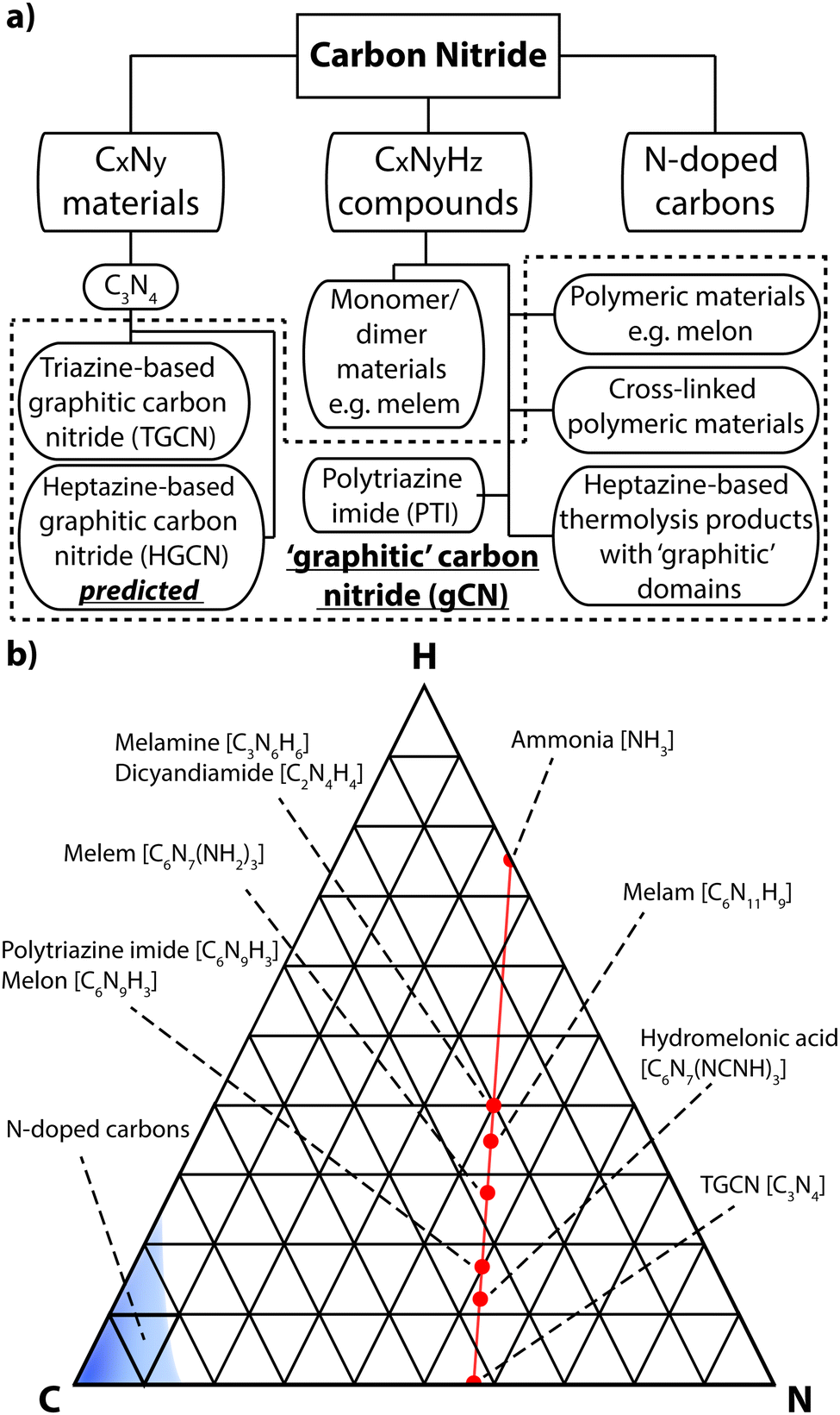 | ||
| Fig. 2 (a) Diagram showing the various classes of carbon nitrides. The dashed box indicates materials often designated graphitic carbon nitride (gCN). (b) Ternary plot of important types of carbon nitride materials projected on to a C–N–H compositional diagram. Semimetallic N-doped graphite and graphene materials cluster near the pure C pole (elemental analysis results based on ref. 29 and 30), whereas stoichiometric gCN compounds are concentrated around a tie-line extending between melamine or DCDA to approximately C2N3H via loss of NH3 component. Complete loss of NH3 would result in C3N4. | ||
In the interests of devising a useful nomenclature that captures the structural and chemical properties of these different types of material, we propose a hierarchical approach (Fig. 2a). We suggest that all of the compounds that are likely to contain layered elements within their structures can be generally referred to as “gCN” or “GCN”, to reflect the fact that carbon and nitrogen are the main components and that at least some elements of the structure can be compared with the extended planes of graphite. When describing specifically those compounds formed by thermolysis and other reactions resulting in polymeric materials related to Liebig's melon it could be appropriate to use terms such as gCN(H) or pCN(H), to further specify the presence of large amounts of H as an essential component and the more or less condensed nature of the amorphous to nanocrystalline structures. The crystalline phases based on imide-linked polytriazine sheets with intercalated ions should be termed PTI·MX, where Mn+ and Xn− refer to the intercalated species. Finally, the specific term “g-C3N4” should be reserved for those materials that are determined to have a composition that closely matches that ideal stoichiometry, with minimal incorporation of hetero-atoms such as H or O, and that are determined to be based on sp2-bonded C atoms. Within that category we could further specify the fully condensed crystalline graphitic layers of “TGCN” (triazine-based graphitic carbon nitride),23,24 and “HGCN” (heptazine-based graphitic carbon nitride) referring to a theoretically predicted range of heptazine-based layered compounds that have not yet been demonstrated experimentally.
We also note that several other classes of materials have also been described as “graphitic carbon nitrides”. These include N-doped graphites or graphenes, that usually contain up to only a few percent nitrogen distributed randomly over the sp2-bonded sites (Fig. 2b).29,30 These materials are typically metallic to semi-metallic that distinguishes them from the semiconducting gCN compounds, that contain alternating N and C atoms in well-defined structural positions determined by local valency rules. However, such N-doped carbons have applications as sensors,35 and for energy storage31 and conversion7 as well as catalysis,32 especially when spatial correlations exist between regions of high nitrogen content and the metal nanoparticles that constitute the catalytic centres.33,34 Related to these are the electrochemically and catalytically active “carbon nitride” materials that have been produced by selectively embedding N-rich domains surrounding metal atom clusters within a predominantly carbonaceous matrix.8
2. Discovery and emergence of carbon nitride materials
2.1. Early history
Following Carl Scheele's seminal work on prussic acid (HCN)36 chemists began to investigate related chemical series, and this led to discovery of compounds containing the thiocyanate (SCN−) anion. Porret37 produced a mercurous variety of the salt and Berzelius first prepared mercury(II) isothiocyanate Hg(SCN)2. Building on the demonstration by Gay Lussac that cyanogen ((CN)2) gas could be produced by heating Hg(SCN)2, Berzelius attempted to form the analogous thiocyanogen ((SCN)2) by heating his new compound.38,39 That experiment was not successful, as large amounts of CS2 and N2 were evolved and HgS sublimed. When Hg(SCN)2 was mixed with elemental sulphur and heated a small quantity of (SCN)2 was produced, along with CS2 and N2. The reaction was violent and the formation of copious amounts of a porous pumice-like solid mass was noted, breaking open the apparatus. In his own attempts to obtain thiocyanic acid (HSCN) by treating Hg(SCN)2 with H2S, Wöhler reported a characteristic “snake-like” appearance of the voluminous porous solid residue that emerged as the salt was burned in air.38,39 That remarkable and seemingly magical property later led to the development of pyrotechnic materials that were packaged and sold as “Pharaoh's serpents” eggs, following a loose reference to the mystical behavior of Moses' staff.40 The commercial enterprise ended as the health and safety implications of releasing mercury and cyanide into the atmosphere became better appreciated, in addition to unfortunate reports of people confusing the wrapped pellets with ingestible sweets. Informative reviews of this early history were published by Irving38 and Davis.39 A recent YouTube video shows the process of producing and then igniting Hg(SCN)2 to form “Pharaoh's serpents”, including the safety considerations that must be respected to carry out the reactions.41 The overall decomposition reaction is written as:| 2Hg(SCN)2 → 2HgS + CS2 + C3N4 |
The carbon nitride forms a yellow-brown porous solid.42
2.2. Liebig's melon and related structures
In a classic series of investigations, Justus, baron von Liebig described the formation and properties of various CxNyHz compounds that were given names such as “melem” (C6N10H6), “melam” (C6N11H9) and “melamine” (C3N6H6) (Fig. 2 and 3).43–45 The work was continued and complemented by others,46 and the extensive series of investigations have helped establish the chemical compositions.42,47 Liebig first applied the term “melon”43 to a yellow, amorphous residue formed by heating to redness the yellow precipitate formed by the action of Cl2 on an aqueous KSCN solution, with no apparent justification for the choice of name (“Wenn man diesen Körper, den ich Melon nennen will…”) (p. 5 in ref. 33). A similar solid product was also obtained by ignition of ammonium thiocyanate (NH4SCN), or from intimate mixtures of KSCN and NH4Cl. The name was also extended to the yellow product formed by heating Hg(SCN)2 in air, that gave rise to the “Pharaoh's serpents” phenomenon described above.42,48 Liebig showed that the composition of his “melon” showed significant variability between different synthesis experiments,43 although the limiting stoichiometry is found to lie near C2N3H (or C6N9H3), with an ideal structural formula determined for the nanocrystalline material as C6N7(NH)(NH2).21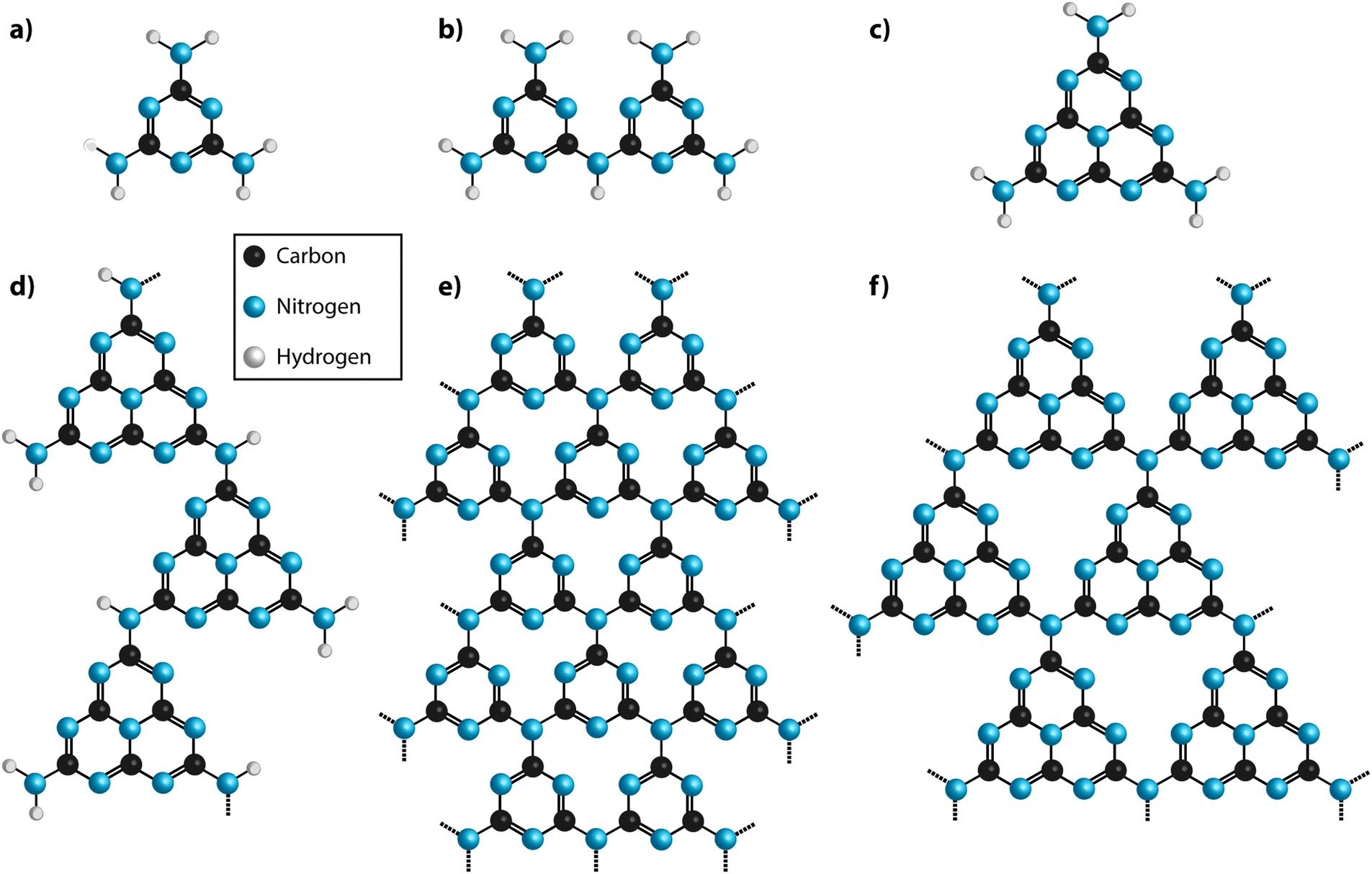 | ||
| Fig. 3 Structural motifs for carbon nitride molecules and solid state structures. (a) Melamine (b) melam (c) melem (d) melon (e) fully condensed triazine based C3N4 structure (TGCN) (f) fully condensed polyheptazine (tri-s-triazine) C3N4 structure. | ||
Typical modern approaches to forming gCN materials related to Liebig's melon involve thermolytic condensation of molecular precursors including melamine (C3N3(NH2)3), cyanamide and its dimer (dicyandiamide, C2N4H4, DCDA), as well as N-rich molecules such as urea (CN2OH4).22,49,50 An early account of the thermolysis pathway from melamine giving rise to products with different CxNyHz compositions was given by May.47 More recent results confirm the suggested general scheme.22,49–51 This synthesis procedure results in polymeric materials that have a limiting composition near that of Liebig's melon, with structures derived from ribbon-like elements formed by linked chains of heptazine (C6N7) units.20–22,49,50,52 Among the amorphous materials produced at higher temperatures, some elements containing more highly condensed graphite-like domains may be present, but this has not been proved experimentally. It might be expected that the end result from continued elimination of NH3 would cause formation of fully graphitic g-C3N4 layers based on linked polyheptazine units (Fig. 3f). Although such structures have been predicted theoretically to constitute the most stable C3N4 polymorph,49,53 they have not been observed in experiments carried out to date. This is due to the high thermal stability of the heptazine-based CxNyHz polymers, combined with the fact that carbonaceous species including C2N2 begin to be released along with NH3 during heating, thus preventing complete condensation into polyheptazine g-C3N4 layers.42,50,51 To date, only two examples of stoichiometric g-C3N4 have been described in the literature.23,24 Both of these materials were formed by alternative synthesis approaches, and they have structures based on layers of simpler C3N3 (s-triazine) structural units linked via sp2-bonded N atoms23,24 (Fig. 3e). Their structures and properties are described below in Section 2.3.
As part of his work to understand the chemistry and structures of the compounds that had begun to be described as “ammono carbonic acids” and carbonic nitrides,42 Franklin sent samples of crystalline Na3C6N9·3H2O to Linus Pauling for X-ray examination. The resulting analyses indicated the presence of an anion, found to have the structural formula C3N3(NCN)33−. That then led to the proposal by Pauling and Sturdivant, supported by electronic structure arguments, that the family of compounds should be based on the cyameluric (C6N7) unit as their fundamental building block.54 That interpretation was supported by chemical investigations and it led to the suggestion that Liebig's polymeric melon was likewise formed from C6N7 units. Finkel'shtein began to refer to the cyameluric nucleus as “sym- (s-) heptazine” to highlight the presence of 7 N atoms within the central ring unit.48 The structure of the parent compound “cyamelurine” or tri-s-triazine (C6N7H3) containing this heptazine core unit was first reported in 1982.55 Komatsu re-investigated Liebig's syntheses of melon and hydromelonate salts that he proposed would constitute precursors to a fully graphitic g-C3N4 solid, that he presumed would be based on sheets of heptazine units linked by trigonal N atoms (Fig. 3f).56,57 Using a combination of advanced characterization techniques and ab initio theoretical calculations, it is now demonstrated that nanocrystalline Liebig's melon is formed by zig-zag chains of heptazine rings linked via –NH– units and terminated laterally by –NH2 groups, that are linked by H-bonding to form layers (Fig. 3).21 The structure of crystalline melem (C6N11H9) was also established using a similar range of techniques.58 Kroke and Schwartz have described the emergence of similar structural motifs based on condensation reactions starting with cyanamide or DCDA, that produce melamine in a first instance.22
All of the fully polymerized g-C3N4 sheet structures based on linked heptazine units predicted by density functional theory (DFT) calculations are indicated to be non-planar, and to have greater stability than layers based on polytriazine networks.49 Gracia and Kroll53 calculated the relative energetics of a wide range of layer stacking sequences and different buckling patterns based on such “corrugated” polyheptazine sheet structures, although none of these have been observed in practice. The only fully-polymerized graphitic C3N4 materials that have been reported to date contain layers based on triazine (C3N3) units linked by sp2-bonded N atoms. Those results are described in the next section.
2.3. Triazine-based g-C3N4 structures
In their first synthesis of an extended triazine-based carbon nitride phase, Kouvetakis et al. used designed unimolecular precursors (Me3E)2N(C3N3)X2 (E = Sn, Si; X = F, Cl) to deposit nanocrystalline thin films via chemical vapor deposition (CVD).24,59 The C3N4 stoichiometry was determined by Rutherford back scattering (RBS), while electron energy loss (EELS) measurements carried out using transmission electron microscopy (TEM) confirmed the presence of sp2-bonded C and N atoms. IR data showed the absence of N–H groups. High resolution TEM imaging and diffraction data indicated a layered structure based on triazine rings linked by three-coordinated N atoms to form graphitic sheets (Fig. 3e). Later theoretical studies then predicted the likely existence of various triazine-based g-C3N4 polymorphs based on different stacking arrangements of the graphitic sheets, so that stacking disorder might be present within the experimental samples.60,61 Algara-Siller et al. were first to report forming bulk crystalline TGCN as a product of condensation reactions involving DCDA in molten salt (LiCl/KCl eutectic mixture) media.23,62 The TGCN compound became deposited as a film on the walls of the glass vessel or at the surface of the molten salt reaction medium. X-ray photoelectron spectroscopy (XPS) and EELS analysis demonstrated that the N:C ratio corresponded to the C3N4 composition, with only a small quantity of included O component.23 Analysis of the TEM images and X-ray diffraction (XRD) data combined with DFT predictions indicated a graphitic g-C3N4 structure, with either AB (space group P![[6 with combining macron]](https://www.rsc.org/images/entities/char_0036_0304.gif) m2) or ABC (P63cm) stacking of the layers, although the likely presence of layer stacking disorder was also noted. More recently, TGCN samples were exposed to high pressure and high temperature conditions in a diamond anvil cell, and new crystalline peaks appeared indicating formation of a new type of C3N4 framework consisting of triazine rings linked by sp3-bonded C atoms, corresponding to structures predicted by ab initio searching techniques.60,61 Such open framework structures have been suggested to be energetically competitive with the graphitic layered compounds, and they could in fact be present within the amorphous materials produced by thermolysis and other reactions at ambient pressure.
m2) or ABC (P63cm) stacking of the layers, although the likely presence of layer stacking disorder was also noted. More recently, TGCN samples were exposed to high pressure and high temperature conditions in a diamond anvil cell, and new crystalline peaks appeared indicating formation of a new type of C3N4 framework consisting of triazine rings linked by sp3-bonded C atoms, corresponding to structures predicted by ab initio searching techniques.60,61 Such open framework structures have been suggested to be energetically competitive with the graphitic layered compounds, and they could in fact be present within the amorphous materials produced by thermolysis and other reactions at ambient pressure.
2.4. Polytriazine-imide (PTI) structures
The production of relatively well-crystallized bulk carbon nitride compounds was reported by Demazeau and colleagues, who used solvothermal reactions involving melamine and cyanuric chloride (C3N3Cl3) in the presence of organic bases (triethylamine or di-isopropylethylamine), under high pressure conditions (140 MPa).63 Chemical analyses showed that substantial quantities of Cl as well as H atoms were incorporated within the structure. Zhang et al. investigated the self-condensation of aminodichlorotriazine as well as reactions between melamine and cyanuric chloride at higher P, T conditions (1–1.5 GPa; 500–600 °C) to form a family of yellow crystalline products that approached a limiting composition C6N9H3·xHCl with x = 1, also formulated as [C6N9H4]+Cl−.25,64 Powder XRD studies revealed series of sharp peaks that were initially interpreted within space group P63/m with a dominant peak interpreted as the basal reflection of a layered graphitic compound at d002 = 3.22 Å.25 The corresponding d002 reflection of crystalline graphite occurs at 3.36 Å.65 EELS measurements established sp2 bonding around the C and N atoms and 13C nuclear magnetic resonance (NMR) spectra showed two non-equivalent C sites with peaks at 166 and 159 ppm in a 2:1 ratio, consistent with protonation of the some of the C atoms within the layers. The combined data indicated a structure with triazine rings linked via –NH– units to form a PTI motif with C12N12 ring voids appearing within the ‘graphitic’ layers (Fig. 4a). The additional HCl components found to be included in the structure from the synthesis reaction results in one additional H+ to become attached to one of the six available N sites on the triazine units surrounding the large ring, while Cl− ions are accommodated within the layer voids. Interestingly, the composition of the basal layer is C6N9H3 (i.e., C2N3H), identical to the limiting stoichiometry of Liebig's melon, as well as that of the defective wurtzite structure containing sp3-bonded C and N atoms prepared from DCDA using high-P, T techniques.66,67
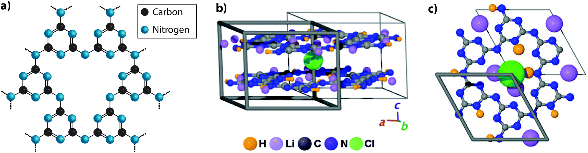 | ||
| Fig. 4 Development of different aspects of the PTI structure. (a) C6N9H3 poly(triazine imide) backbone. H atoms are bound in the three bridging imido groups linking between triazine units and pointing towards the centre of the C12N12 layer voids. (b) Schematic depictions of PTI·LiCl layered structure determined by Wirnhier et al.26 (c) Further details of the H+ and Li+ positions have been determined using multidimensional solid-state NMR techniques along with PDF analysis of X-ray and neutron diffraction data.27 Reprinted with permission from ref. 27. Copyright John Wiley and Sons. | ||
Bojdys et al. later produced related crystalline materials by reaction of DCDA in a molten salt (eutectic LiCl–KCl) solvent system. A combination of analysis techniques revealed compositions near C6N8.5H1.5Li0.8Cl0.2. XRD patterns showed extended series of sharp peaks that were indexed within space group P63cm with the strongest feature indicating an interlayer (d002) spacing of 3.36 Å. The initial structural model proposed for this material contained layers based on linked polyheptazine units, however a detailed structural analysis carried out by Wirnhier et al.26 for a crystalline compound with composition C12N17.5H6.3Cl1.5Li3.3 led to a different interpretation. It was concluded that the new phase had a structure based on polytriazine imide-linked units,26 related to that proposed by Zhang et al.25 for C6N9H3·HCl, but with differences concerning the location of Cl−, H+ and Li+ ions within and between the layers. In this crystalline material, the H+ ions within –NH– bridging species are partially replaced by Li+, causing the Cl− ions to be forced out of the intralayer void positions to occupy new sites intercalated between the sheets (PTI·LiCl). Additional charge-balancing Li+ ions were modeled to exist within interlayer sites (Fig. 4b and c). In further experiments using LiBr/KBr as the eutectic molten salt combination, Chong et al. produced additional PTI based materials containing ions such as Br− (PTI·LiBr) between the layers,68 demonstrating that controlling the size of the intercalated ions alters the interlayer spacing, as well as the stacking pattern. Recent studies using multi-dimensional NMR techniques combined with pair distribution (PDF) analysis of the diffraction data are now providing an even more detailed view of the local structural arrangements in these crystalline PTI compounds, specifically concerning the locations of H and Li atoms or ions within the voids (Fig. 4c).27 It should be noted that all PTI materials examined to date maintain a significant H concentration as an essential component of their structure, as the substitution by Li is always only partial.25,26,68,69
3. Characterization of carbon nitride materials: techniques and challenges
Here we summarize techniques used to characterize the chemical composition and structural nature of different classes of carbon nitride materials. We note that due to certain challenges associated with both the particular techniques and the nature of the materials themselves, understanding the chemistry and structure of these solid state compounds remains a project that is still under development. In this section we highlight results that have been obtained to date, while pointing out areas that still need attention.3.1. Compositional analysis
Determining reliable chemical compositions for amorphous to nanocrystalline solid-state materials built from combinations of the “light” elements C, N and H is always challenging, especially when these can contain significant concentrations of other elements such as O, as well as Li, Cl and Br. In early investigations into various CxNyHz compounds, the bulk elemental compositions were determined using classical chemical analysis methods along with gravimetric techniques. Modern studies typically apply commercial CHN(O) analyzers that employ flash heating to 900–1000 °C, followed by catalytic oxidation and reduction reactions in an inert gas stream.70 Thermogravimetric analysis (TGA) is also applied during controlled step heating combined with mass spectrometric analysis to determine the gaseous species evolved, with complementary data on phase changes and thermal decomposition reactions obtained from differential thermal analysis (DTA) or scanning calorimetry (DSC) techniques. NH3 is typically evolved from precursors such as melamine and DCDA above approximately 450 °C, with C2N2 and volatile CxNyHz species, not all of which have been identified, appearing in the gas phase at higher temperatures (480–540 °C). Final decomposition to yield refractory N-doped carbon materials (CNx, with residual N contents ranging up to a few per cent) occurs above 680 °C (Fig. 5).22,49–51 The evolution of gaseous C2N2 and other C-containing species in the intermediate temperature range highlights the fact that such thermolysis reactions cannot be used to attain the ideal C3N4 stoichiometry, that would be predicted to constitute the end result of simply removing NH3 component from the N-rich molecular precursors (Fig. 2b). Instead, the limiting compositions for gCN(H) materials produced in this way appear to lie close to C2N3H, corresponding to those of Liebig's melon (C6N7(NH)(NH2)) or hydromelonic acid (C6N7(NCNH)3),22,49–51 as well as that of the graphitic layers found in crystalline PTI compounds,25,26 and also the sp3-bonded phase with a defective wurtzite structure produced under high-P, T conditions.66,67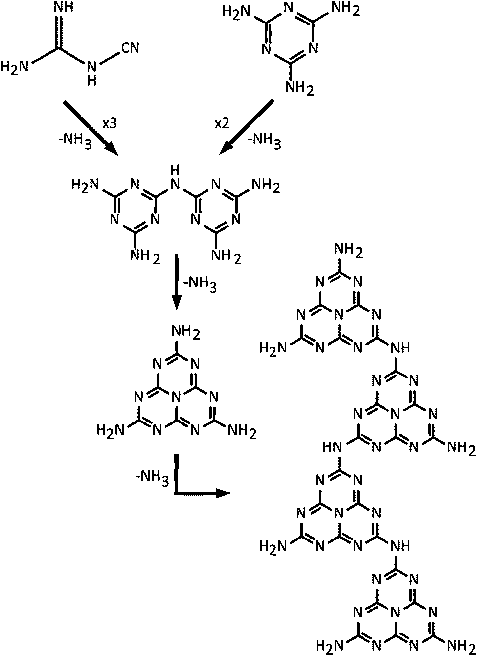 | ||
| Fig. 5 Sequence of polymerization reactions proposed for dicyandiamide or melamine leading to Liebig's melon via condensation and elimination of NH3 components. Further condensation reactions could ultimately lead to sideways cross-linking of polyheptazine ribbons to form sheet-like structures, but no fully polyheptazine based g-C3N4 has been observed to date. | ||
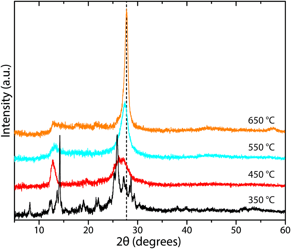
Many studies have reported compositional data for CxNyHz materials prepared for different applications using such thermolysis reactions. Although it is usual for substantial quantities of H to be recorded as a major component of the gCN compound, we note that many of the publications go on to describe the material as “g-C3N4”, in the title and abstract as well as throughout the main text. This practice is misleading. In recent work from our group, we prepared series of gCN compounds from a 1:1 mixture of DCDA and melamine heated to 550–650 °C in an N2 atmosphere. As expected, the C:N ratio increased and the H:C ratio decreased with increasing synthesis temperature due to loss of NH3 as the condensation reaction proceeded (Fig. 6). However, even after synthesis at 650 °C the H:C ratio remained close to 0.5. Exposure to air or moisture can result in additional O and H2O being incorporated within the samples, and this can affect the determination of C:N:H abundances and elemental ratios.
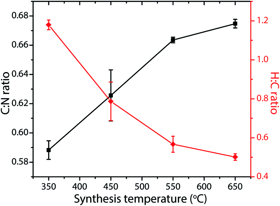 | ||
| Fig. 6 C:N and H:C atomic% ratios in gCNs produced from 1:1 melamine:DCDA mixtures as a function of synthesis temperatures between 350–650 °C. | ||
Crystalline PTI materials typically contain Li+, Cl−, Br− or other species included within their structures.25,26,69,71 The concentrations of these elements must be determined independently by other techniques, including inductively coupled plasma mass spectrometry (ICP-MS), electron microprobe or quantitative scanning electron microscopy (SEM) using energy-dispersive X-ray spectroscopy (EDX) analysis,72 X-ray photoelectron spectroscopy (XPS),73 EELS and RBS.24 The results of the different analyses must then be combined to give a best estimation of the chemical composition of the material that has been synthesized. Quantitative determination of Li contents is particularly challenging. EELS spectra give quantitative information on C, N, O contents as well as heavier elements such as Cl or Br, but not for the lightest components including H and Li.25 ICP-MS methods require the materials to be pre-digested, requiring complex and aggressive procedures that can affect the determined compositions.1,69 XPS analysis is particularly challenged by the presence of a strong signal from “adventitious” carbon,74 as well as uncertainty in some of the characteristic peak assignments: these are discussed in detail below. This introduces further potential errors into the compositional determination. In a few cases, the determined concentrations of some of the elements have been compared using different techniques, to give an idea of the actual composition along with the associated analytical errors.25,26 Additional information on the site occupancies of some of the elements can also be obtained from Rietveld analysis of the X-ray diffraction patterns, and more recently neutron scattering data, and from quantitative NMR measurements.27
3.2. X-ray photoelectron spectroscopy (XPS)
XPS has become a standard tool for chemical and surface structural analysis of materials. It is typically applied to carbon nitride samples to determine their N:C ratios, local bonding environments, and the presence and concentration of heteroatoms such as O.73 It is a surface analysis technique, probing the top 1–10 nm of samples, and therefore the extent to which the surface structure truly represents the bulk composition must be taken into account. Powdered samples are typically mounted on carbon tape and the kinetic energies of electrons emitted following irradiation by X-rays of known wavelength are measured, creating a spectrum of the characteristic binding energies (BE) for elements contained within the sample (Fig. 7). Small chemical shifts in the BE examined at higher energy resolution then provide information on the local coordination, bonding environments and oxidation state. The signals are typically fitted with Gaussian or mixed Gaussian–Lorentzian (GL) components to determine the relative concentrations of various species contributing to the overall lineshape. The extent of any surface contamination can be evaluated by eroding the sample surface with a beam of Ar atoms applied during the analysis. Importantly for studies of the semiconducting carbon nitrides, the BE values can be modified by charging effects during spectral acquisition. An electron flood gun is typically used to counteract this effect,75 and the position of a standard C–C environment (BE ∼284.8 eV) is typically used to calibrate the resulting spectra.
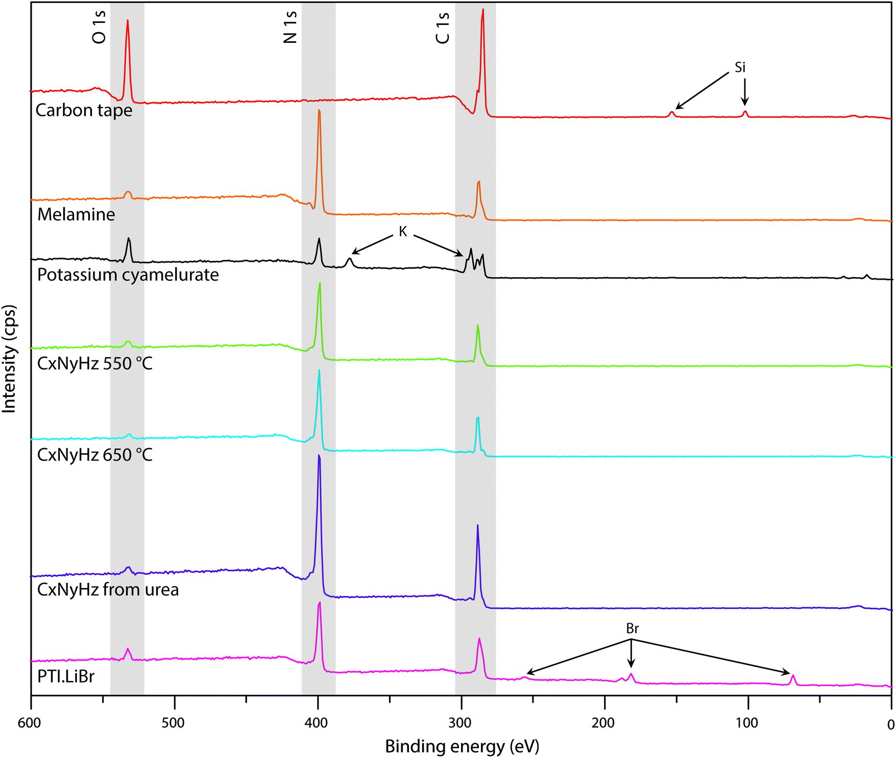 | ||
| Fig. 7 XPS survey spectra of C tape typically used to mount samples along with various carbon nitride materials. | ||
A primary obstacle to obtaining quantitative XPS analyses of carbonaceous materials is the presence of an “adventitious” C1s signal (Cadv) that partially derives from the carbon tape that is used to mount the samples. Powdered materials can also be pressed into malleable metal foils to avoid this problem, but this has rarely been applied in gCN studies. Other Cadv contributions can also arise from contamination of the sample surface during handling in the atmosphere, or from degassing processes within the instrument itself. In order to help identify such problems and aid in future interpretation of C1s spectra, we discuss the standard spectrum obtained for carbon tape, before presenting the analysis of data for several typical carbon nitride materials (Fig. 7 and 8).
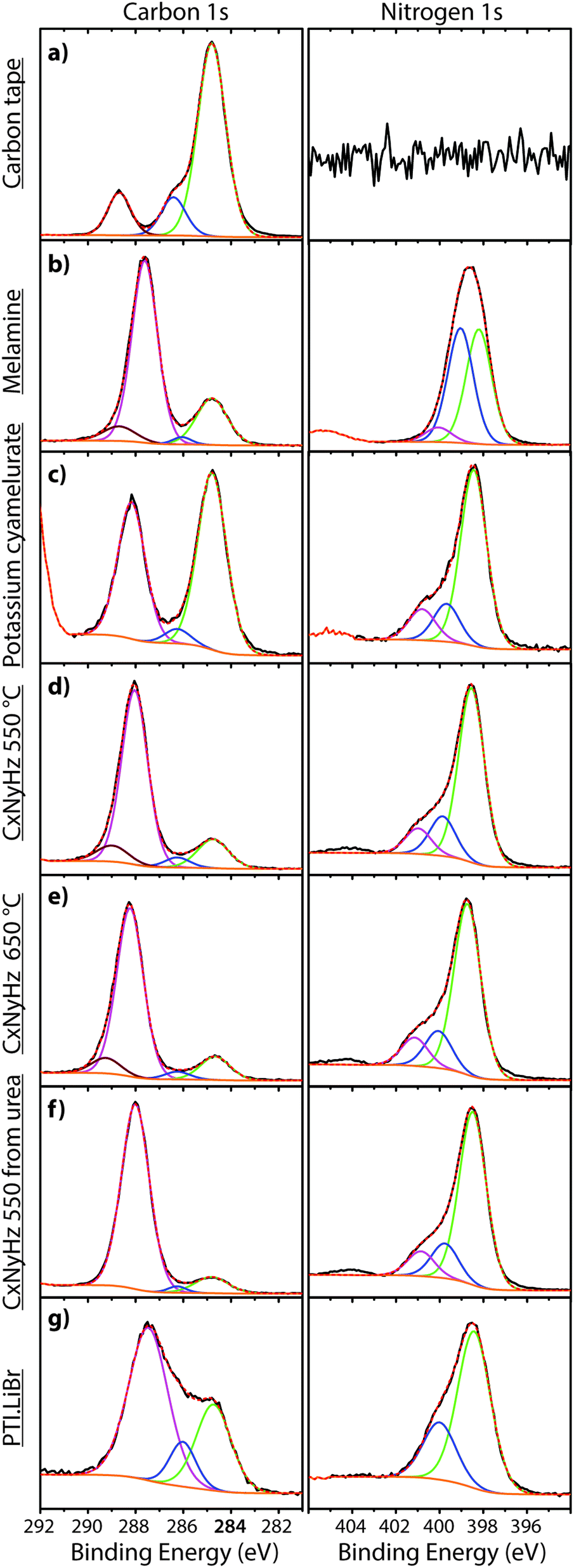 | ||
| Fig. 8 XPS spectra of carbon tape and CxNyHz based materials in the regions of C1s (left) and N1s (right): (a) carbon tape, (b) melamine, (c) potassium cyamelurate, (d) CxNyHz-550 °C, (e) CxNyHz-650 °C, (f) CxNyHz from urea, (g) PTI·LiBr. The Y axis in all cases is the intensity of the emitted photoelectron signal (c.p.s) as a function of the binding energy. | ||
In addition to the C1s peak near 280 eV, the carbon tape survey spectrum shows a strong signal due to O, as well as features assigned to Si (Fig. 7). The minor Si component could be derived from mineral particles (e.g., SiO2) deposited from the laboratory atmosphere, that could also contribute to the O signal. However, most of the much larger O signal likely indicates surface oxidation of the C-tape. Examination of the C1s region shows a main C–C peak at 284.8 eV, with a shoulder at higher BE (286.1 eV). A further weak peak emerges at 288.7 eV after careful fitting of the baseline in the region. The three contributions are fit using GL lineshapes (Fig. 8a). The weak peaks at higher BE values are typically interpreted as due to C–O (286.1 eV) and O–C![[double bond, length as m-dash]](https://www.rsc.org/images/entities/char_e001.gif) O (288.7 eV) species, indicating surface oxidation of the carbon film. There is no evidence for N present.
O (288.7 eV) species, indicating surface oxidation of the carbon film. There is no evidence for N present.
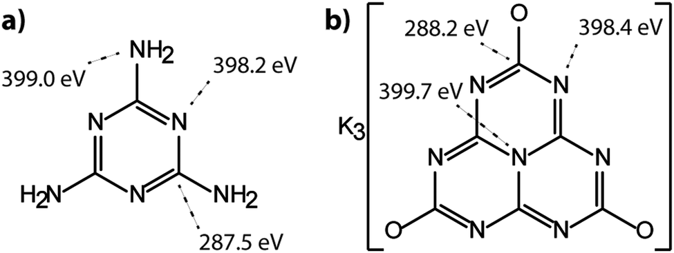
The molecular crystal melamine contains the isolated s-triazine unit with three –NH2 substituents (Fig. 9a).22 The XPS survey spectrum of this material clearly shows the presence of a strong N1s peak near 400 eV (Fig. 7). An O1s signal is also present in the same position as that observed for the underlying C tape, but with considerably lowered intensity, and it is likely that it could be derived from the supporting material. The C1s spectrum is dominated by a single peak at 287.5 eV that is clearly distinguished from the Cadv signal, and that is readily assigned to the sp2-bonded carbon atoms bonded to N within the s-triazine ring (Fig. 8b).76 The corresponding N1s spectrum shows a broad band that appears to be symmetric but can be deconvoluted to reveal two main GL components in a 1:1 ratio consistent with the molecular structure (Fig. 8b). The contribution at 398.2 eV is assigned to the C–NC nitrogen atoms within the triazine rings, and that at 399.0 eV to the C–NH2 groups, based on electronegativity considerations. The fitting procedure also reveals a further small component with BE = 400.1 eV, that has been assigned to a resonance form of the melamine structure involving the –NH2 group, similar to that found for aniline.76
 | ||
| Fig. 9 Structural representations of molecular carbon nitrides with characteristic binding energies indicated for specific sites and groups within the compounds: (a) melamine. (b) Potassium cyamelurate (KCM). | ||
To provide a similar model for heptazine-based structures we prepared potassium cyamelurate (KCM: C6N7O3K3, Fig. 9b) as white, acicular crystals with composition C: 19.18% (calculated: 21.5%), N: 28.93% (calculated: 29.2%), with some additional H content (0.28%).138 The C1s spectrum (Fig. 8c) showed a single peak at 288.2 eV in addition to the Cadv contribution, that can be assigned to the unique C environment inside the heptazine rings. We note that the BE of this peak occurs at nearly the same position as that for melamine (287.5 eV), thus demonstrating that C1s XPS peak positions cannot be used to distinguish between the triazine and heptazine units that are potentially present within different gCN structures. Features observed near 284 and 380 eV arise from the K2p spectrum (Fig. 7). The only N atoms present in KCM are contained within the heptazine ring,66 providing an opportunity to study the relative electronegativity of the different N sites (Fig. 9). The N1s spectrum shows a dominant peak near 400 eV with a shoulder at higher BE values (Fig. 8c). The spectrum can be deconvoluted into three GL components. The main peak at 398.4 eV is readily assigned to the outer –C–NC– environments by analogy with that found at 398.2 eV for melamine, whereas the smaller 399.7 eV peak is attributed to the central N–C3 unit. This BE value is very close to that for the N environment in triphenylamine. The observed ratio of the peak areas (1:0.22) is close to that expected (1:0.17) from the molecular structure. An additional contribution from –C–N–H species within the structure is suggested to be present at 400.8 eV (Fig. 8c).
To illustrate the XPS spectra for gCN compounds prepared by thermolysis reactions from molecular precursors we compare data obtained from products of a 1:1 melamine/DCDA mixture treated at 550 and 650 °C in NH3 atmospheres (see Fig. 6),77 with that of a sample prepared from urea (CH4N2O) heated to 550 °C in air78 (Fig. 7 and 8d–f). All of the materials exhibited a weak O1s signal. However, the O content indicated for the gCN sample derived from urea is lower (∼2%) than those recorded for the other materials (∼4%). This observation could be related to a “self-supporting atmosphere” effect suggested by previous authors to have developed during the synthesis reaction.78 The C1s spectra of all three samples are similar, with a main peak near 288 eV assigned to sp2 bonded C atoms associated with triazine or heptazine units (Fig. 8d–f). The N1s spectra are also nearly identical, showing a dominant feature near 398.6 eV that is assigned to C–NC units within either triazine or heptazine rings, along with a contribution at 401.1 eV giving rise to a shoulder at higher BE indicative of C–N–H uncondensed amino (–NH2) groups, and a further weak component at 399.9 eV that is assigned to the central N atoms bridging between three heptazine rings (N–C3 units) (Fig. 8d–f). Within a fully condensed heptazine-based g-C3N4 structure we would expect the ratio of C–NC to N–C3 units to be close to 1:0.33. However, the area ratios determined for gCN samples prepared by thermolysis reactions are always significantly lower than this, indicating that the compounds do not correspond to fully condensed graphitic structures.
To study the bonding properties of a gCN material containing fully condensed sheets formed from independent s-triazine rings connected by imido –NH– units, we obtained the XPS spectrum of crystalline PTI·LiBr (Fig. 7 and 8g).26,27 The presence of Li is indicated by the weak 1s feature at BE = 54.9 eV (Fig. 10a). Although this can be fitted by a single GL component, it is broader than the equivalent peak for rocksalt-structured LiBr, suggesting that a range of Li environments is present within the PTI structure. That suggestion is consistent with results of detailed structural analysis of PTI materials.26,27 This effect is also noted for the Br 3d region, that contains two peaks due to spin–orbit (I = 3/2, 5/2) coupling. The C1s spectrum of PTI·LiBr is different from those for polymeric to graphitic CxNyHz materials. Apart from the adventitious Cadv signal at 284.8 eV, there is a strong peak at 287.5 eV and a weaker one at 286.1 eV, that were assigned by Schwinghammer et al. for the related crystalline material PTI·LiCl to “sp2 carbon atoms bonded to N inside the triazine ring”.1 However, structural models for the PTI materials only allow for a single C environment within the imide-linked triazine rings (Fig. 4), and so the origin of these two features remains undetermined at present. A similar second weak peak observed in the C1s spectrum for the bulk crystalline g-C3N4 compound TGCN has been assigned to the presence of terminal –C![[triple bond, length as m-dash]](https://www.rsc.org/images/entities/char_e002.gif) N units, although no features corresponding to these groups appeared to be present in the reported IR spectra.23
N units, although no features corresponding to these groups appeared to be present in the reported IR spectra.23
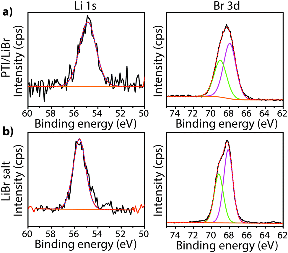 | ||
| Fig. 10 Li1s and Br3d XPS spectra of crystalline (a) PTI·LiBr and (b) LiBr. | ||
The XPS spectra for a TGCN sample prepared by Algara-Siller et al.23 are reproduced in Fig. 11. The N1s region contains peaks at 398.5 eV and 399.9 eV assigned to N–C3 (bridge) and CN–C (ring) environments respectively. However, the C1s spectrum shows a prominent C–C feature at 284.7 eV, that was assigned by Algara-Siller et al.23 to adventitious carbon, and two further peaks at 286.7 eV and 288.1 eV with an area ratio of 1:0.56, assigned to terminal sp-bonded carbon atoms in CN groups and sp2 carbon (ring) atoms, respectively.23 The peak at 286.7 eV is notably larger than that of the sp2 triazine ring peak (288.1) and is significantly more prominent than in any of the other gCN materials studied. This peak lies close to BE values that are typically associated with surface C–O species, and Algara-Siller et al. did note the presence of O component in their sample23 (Fig. 11).
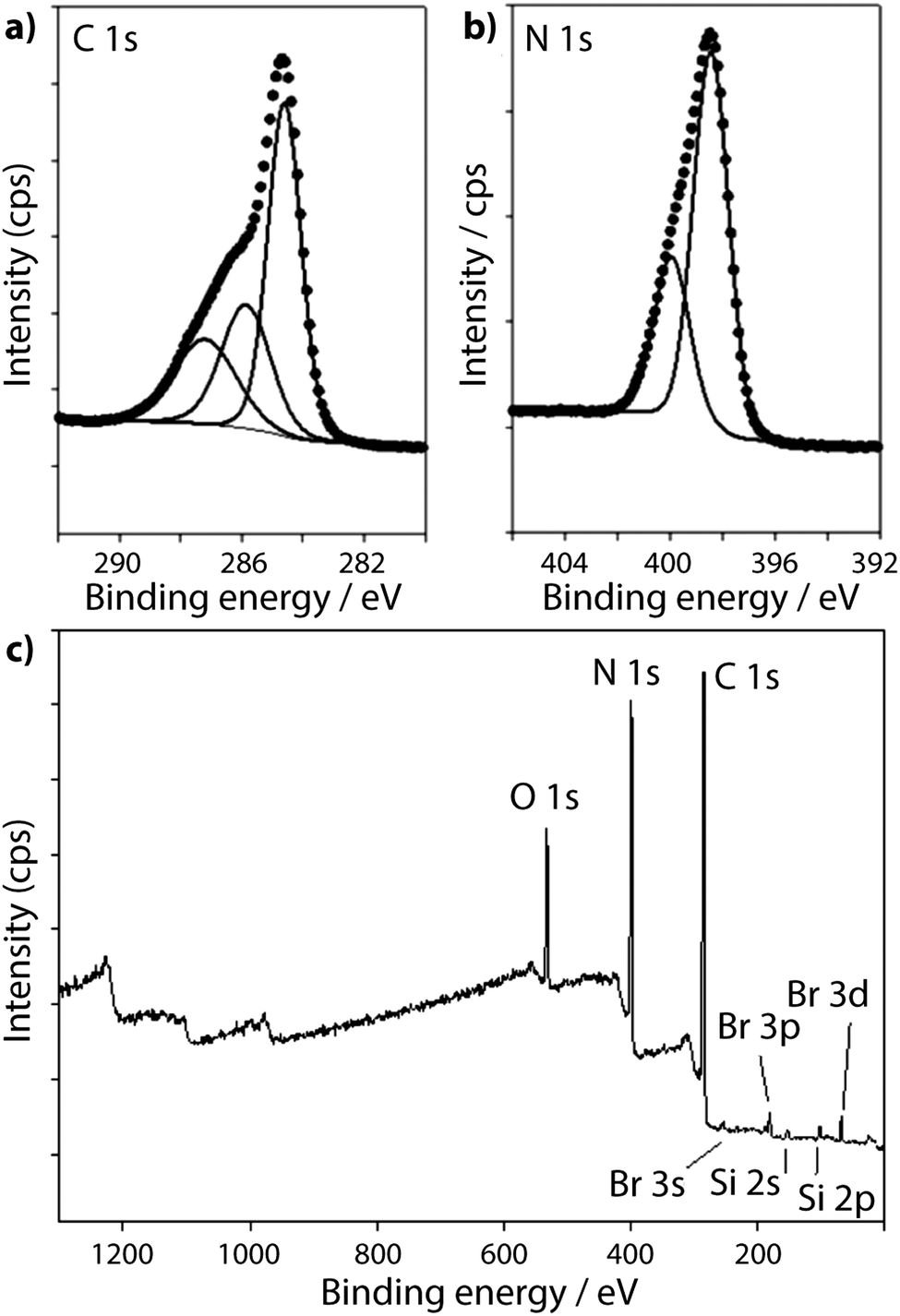 | ||
| Fig. 11 XPS spectra of TGCN from Algara-Siller et al.:23 (a) C1s spectrum (b) N1s spectrum and (c) Survey spectrum. Reprinted with permission from ref. 23. Copyright John Wiley and Sons. | ||
Our conclusion is that XPS represents a primary analysis tool for studying both the chemical composition and the local structural environments in gCN materials. It must be applied with care and attention to details such as proper analysis of signals derived from the underlying C-tape support as well as other contributions to the Cadv lineshape, including evaluation of likely origin of O components in the XPS spectra. There are main issues remaining related to the assignment of C1s and N1s peaks and minor components contributing to the overall line profile, in all types of amorphous, crystalline and polymeric materials examined to date. These must continue to be examined and interpreted, as they not only contribute to determination of the C:N:H:(O) ratios present within the bulk gCN material and at its surface, but also to the study of the intrinsic structure as well as defects present within it. Both areas of future investigation are critically implicated in determining the functional properties of gCN compounds, and they will help define synthesis and tuning parameters for future materials design.
3.3. X-ray diffraction (XRD)
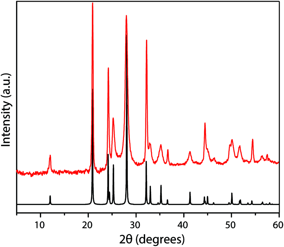
X-ray diffraction is a primary technique used in determining the structures of crystalline and polymeric solids.79 Most gCN materials exhibit XRD patterns that contain only a few broad features, consistent with their amorphous to nanocrystalline nature. They are typically dominated by a main peak at approximately 26–28° 2Θ (Cu Kα radiation), that is usually interpreted as an indication of the presence of a “graphitic” structure, with an interplanar spacing of 3.2–3.4 Å.2,9,78 However, it is important to note that this is not a definitive criterion for such a definition: any compound containing discotic components stacked in an approximately planar arrangement, or polymeric units arranged with an approximately regular spacing, would also give rise to a similar pattern. The observation of the characteristic XRD pattern for gCN materials does not thus immediately imply the presence of graphitic sheets within the structure. Substantial advances in elucidating the structure of polymeric CxNyHz materials related on Liebig's melon have been achieved recently by modelling both the X-ray and neutron scattering patterns, including PDF analysis of data obtained over an extended Q range.20,52 It is useful to begin a discussion with the expected diffraction properties of crystalline to highly disorded C-graphite.Perfectly crystalline graphite contains planar sheets that are stacked according to an AB pattern with P63/mmc space group symmetry, with the centres of hexagons in each sheet lying above and below the sp2 bonded atoms of adjacent layers. The diffraction pattern is dominated by an intense d002 reflection corresponding to an interlayer spacing of 3.36 Å.80 Different “graphitic” forms of carbon that exhibit various degrees of disorder in the relative orientation, stacking arrangements, planarity and lateral extent of the layers, all maintain a similar XRD pattern that becomes broadened and with its main peak shifted to larger d values, as the level of disorder increases.65
The XRD pattern of crystalline TGCN (Fig. 12a and b) has been observed to contain a main peak near 26.5° 2Θ, accompanied by a second feature at approximately 24° 2Θ, with further weak reflections near 50 and 56° 2Θ.23 The diffraction pattern was analyzed within space group Pm2 assuming AB stacking of planar C3N4 layers, although analysis of TEM images presented in the same study suggested ABC (P63cm) layer stacking. It was also noted that stacking disorder might be present within the sample, however. Our simulated XRD patterns for both stacking arrangements assuming a planar geometry for the g-C3N4 sheets appear similar (Fig. 12c). However, DFT calculations indicate that the layers should in fact exhibit more or less substantial buckling.23 Stacking buckled g-C3N4 sheets into either AB or ABC patterns in fact causes the subsidiary peak to occur on the opposite (high angle) side of the main reflection (Fig. 12). That result indicates that the true structure of TGCN may not yet be fully resolved, although the TEM results and compositional analyses do clearly indicate the triazine-based nature of the g-C3N4 layers.
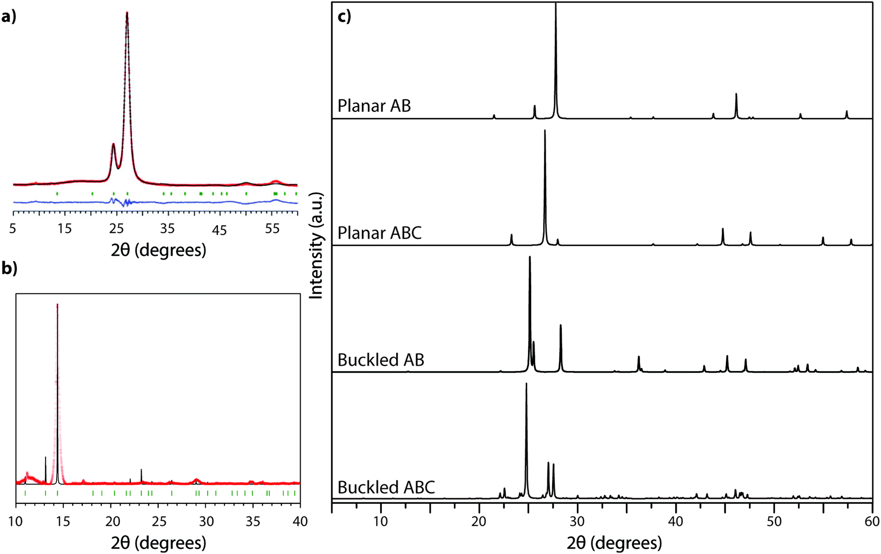 | ||
| Fig. 12 XRD analysis of TGCN: (a) XRD pattern (Cu Kα radiation) collected in reflection geometry observed pattern in red, refined profile in black, difference plot in blue, Bragg peak positions in green. Reprinted with permission from ref. 23. Copyright John Wiley and Sons. (b) Synchrotron PXRD data (λ = 0.827127 Å) on ground TGCN flakes. Reprinted with permission from ref. 23. Copyright John Wiley and Sons. (c) Simulated powder XRD patterns (Cu Kα radiation) for different stacking models of planar vs. buckled g-C3N4 layers. (a) Planar AB stacked (b) planar ABC stacked (c) buckled AB stacked (d) buckled ABC stacked. | ||
The family of PTI compounds containing Cl−, Br− or other anionic species intercalated within or between the layers also exhibit a crystalline series of relatively sharp diffraction peaks in their powder XRD patterns (Fig. 13).25–27 However, in these compounds it is important to note that most of the XRD peak intensity is derived from scattering by the “heavy” elements Cl and Br, that are maintained in their crystalline positions by the carbon nitride layered structure and thus act as a proxy for that arrangement. It is also important to note that the heavy anion sites may not be completely filled, but as long as their scattered X-rays interfere coherently over an appropriate length scale they give rise to “crystalline” diffraction lines. Unfortunately for a general interpretation of these PTI structures, structure drawing programmes and schematic figures that appear in publications usually only depict structures with completely filled sites, and these structures may not be energetically favourable due to repulsive interactions between the large anions in close proximity to each other. It is also difficult to model such structures with partial occupancy of the anion and other sites theoretically, especially when the local distribution of atoms (such as the Li+ or N–H sites around the C12N12 rings, or intercalated between the layers) might be disordered. Models used to predict and analyze their X-ray diffraction patterns typically rely on assuming a partial occupancy of sites. Accepting the boundaries imposed by these limitations, we present a series of calculated XRD patterns for PTI·LiBr and PTI·HCl compounds showing the effects of gradually changing the halide ion concentration on the calculated XRD patterns, that could be useful in future structural analyses (Fig. 14).
 | ||
| Fig. 13 Powder XRD pattern (Cu Kα radiation) of PTI·LiBr prepared from DCDA precursor in LiBr–KBr eutectic molten salt route (red). The predicted XRD pattern for a fully occupied structure is shown in black. | ||
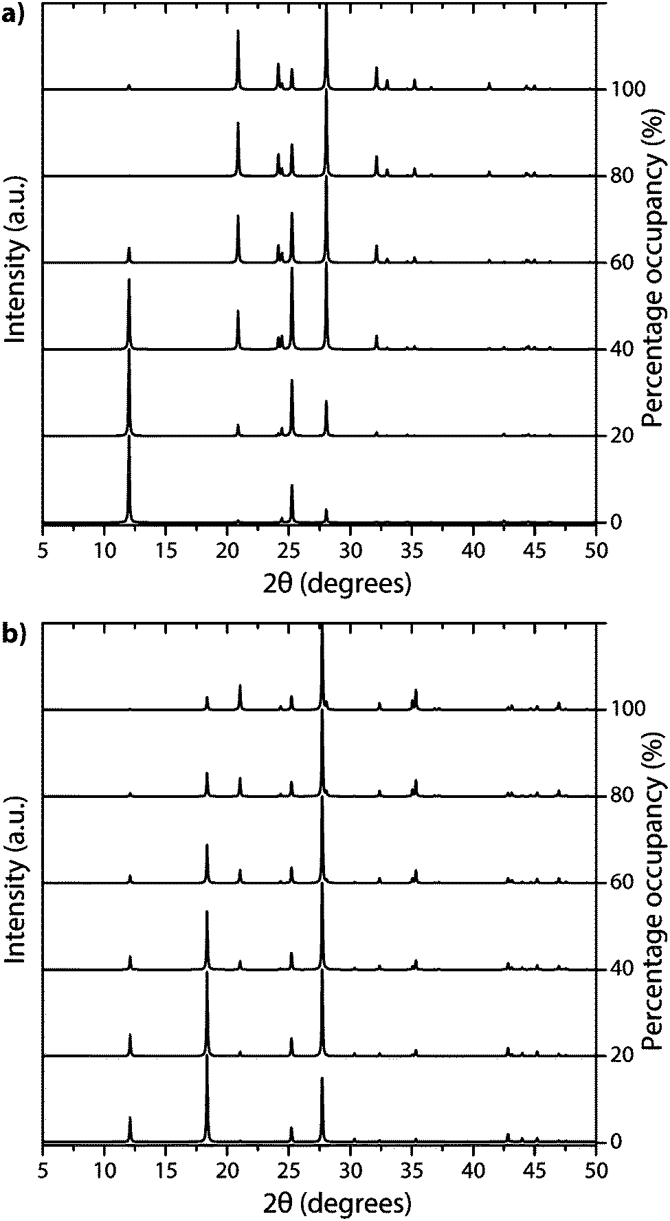 | ||
| Fig. 14 Calculated XRD patterns of PTI with different halide ion concentrations contained within (a) PTI·LiBr and (b) PTI·HCl structures. | ||
Jürgens et al. determined the crystal structure of melem (2,5,8-triamino-tri-s-triazine, Fig. 3 and 15a) using powder XRD data interpreted using Rietveld refinement techniques, combined with solid-state NMR, vibrational spectroscopy and DFT calculations.58 The C6N7 heptazine core was found to be nearly planar. Layers of C6N7(NH2)3 were stacked approximately parallel to the a axis with alternating stacking motifs appearing along the c direction. The C6N7(NH2)3 molecules were linked sideways in the crystal structure by H-bonding to N atoms of adjacent heptazine cores (Fig. 15a). Lotsch et al. addressed the related outstanding problem of determining the structure of Liebig's melon and demonstrated the existence of a high degree of two-dimensional order within the nanoscale domains of the crystalline material they prepared, using a similar range of complementary diffraction, spectroscopic and theoretical methods.21 The melon structure projected on to the a–b plane consists of zig-zag ribbons of heptazine units linked laterally to form extended sheets via H-bonding involving the terminal –NH2 units to bridging –NH– groups and –N units in adjacent polyheptazine ribbons (Fig. 15b).
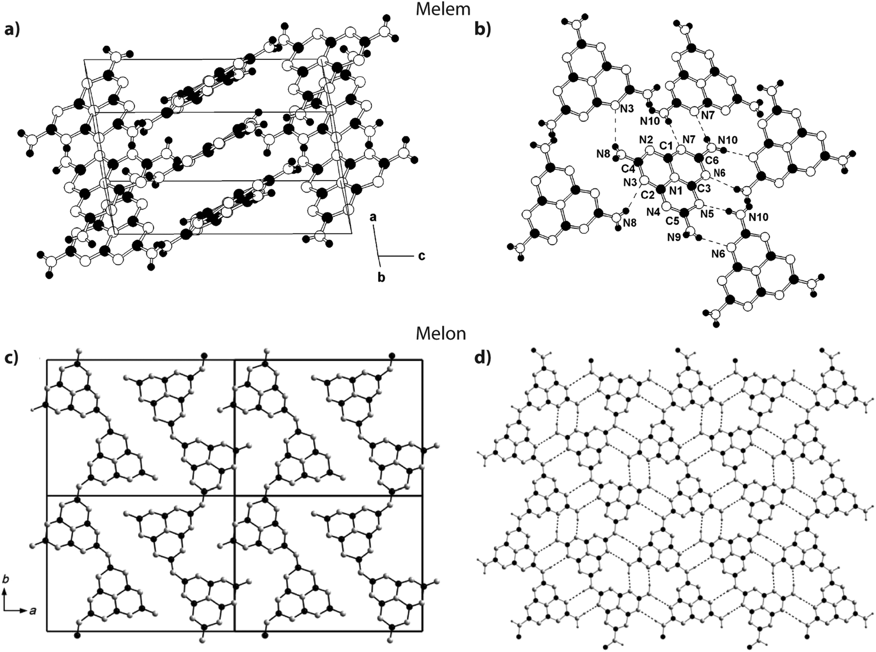 | ||
| Fig. 15 Structures of melem and Liebig's melon. (a and b) Crystal structure of melem. Reprinted (and adapted) with permission from ref. 58. Copyright (2003) American Chemical Society. (c and d) Crystal structure of melon. Reprinted with permission from ref. 21. Copyright John Wiley and Sons. | ||
The XRD patterns of amorphous polymeric to graphitic CxNyHz materials prepared by thermal condensation from molecular precursors typically show a much smaller number of highly broadened features, that are dominated by a peak in the 25–30° 2Θ range (Fig. 16). This is usually assigned as the “002” feature of a graphitic structure, indicating the interlayer spacing dimension. A second broad feature with lower intensity is also observed near 6.7 Å, that has been associated with structural correlations occurring between heptazine ring units within the presumed “graphitic” layers. Tyborski et al. have described the analysis of a “unit cell” based on partially condensed polyheptazine sheets, developed from the ribbon-like structures present within the melon structure.20 Fina et al. recently presented a careful analysis of powder X-ray and neutron scattering data including PDF profiles obtained over a wide Q range.52 Both studies demonstrated that structural models based on triazine layers such as those that occur within TGCN could not account for the diffraction features of the gCN (i.e., polymeric CxNyHz) materials, and that these were most likely dominated by polyheptazine units similar to those found in Liebig's melon. They might also contain more laterally condensed features that could correspond to “graphitic” domains within the amorphous to nanocrystalline structures.
 | ||
| Fig. 16 XRD patterns for gCN materials prepared from 1:1 melamine/DCDA mixtures under N2 flow over a range of synthetic temperatures. The crystalline peaks at 350 °C correspond to those of the starting materials melamine and DCDA. | ||
Our conclusion is that challenges still remain for full interpretation of the XRD patterns of all types of gCN materials, ranging from the polymeric CxNyHz solids produced by thermolysis reactions to highly crystalline “g-C3N4” and PTI materials formed by CVD, molten salt synthesis, or high-P, T treatment. The data to date do indicate that most gCN(H) compounds produced by thermolysis from molecular precursors have a polyheptazine structure, that is most likely related to Liebig's melon but that could contain more laterally extended “graphite-like” units, but with a limiting composition near C2N3H. In contrast, the crystalline PTI phases are defined by extended planar structures, also with a base composition near C2N3H, but based on imide-linked (–NH–) polytriazine units to form graphitic layers containing large (C12N12) voids. Finally, the reported TGCN materials do appear to constitute fully-condensed g-C3N4 structures containing C3N3 rings linked through sp2 bonded N atoms to form graphitic sheets with smaller (C6N6) ring voids within the layers (Fig. 3). An analogous structure based on condensation of polyheptazine units is predicted theoretically to be more thermodynamically stable, but it has not been observed in experiments to date.
3.4. Vibrational spectroscopy
Vibrational spectroscopy methods, especially infrared (IR) absorption spectra obtained using powder transmission or more recently by attenuated total reflection (ATR), constitute a powerful family of techniques that are widely used for structure elucidation as well as chemical analysis of all classes of molecular, polymeric and solid state compounds. Early results applying IR spectroscopy to the CxNyHz compounds melam, melem and melon first appeared in publications by Spiridinova and Finkel'shtein, who used the data to help develop structural models for these intriguing materials.48,81–85 An important observation for evaluation of current gCN materials as well as results reported in the literature is that the IR spectra of nearly all the compounds that have been examined to date contain prominent N–H stretching bands between approximately 2800–3200 cm−1, demonstrating that they are best described as CxNyHz structures, rather than the “g-C3N4” designation that is commonly and erroneously applied to them.3,15,19,86–94We must examine the nature of characteristic features of the IR spectra of various gCN materials to evaluate their contribution to the structure determination of these elusive compounds. We begin with features in the N–H stretching region (typically between 3000–3200 cm−1, but perhaps extending to lower wavenumbers due to H-bonding as well as other specific interaction effects). Generally, the observation of sharp peaks at high wavenumber values indicates a highly ordered structure with few possibilities for N–H sites and local environments, and limited H-bonding between neighboring units. The –NH2 stretching vibrations of crystalline melamine (C3N3(NH2)3) give rise to two sharp N–H stretching peaks at 3469 and 3419 cm−1 in the IR spectrum due to symmetric and antisymmetric modes that are hardly affected by H-bonding within the molecular solid, along with broader bands at 3334 and 3132 cm−1. The IR spectrum for melem (C6N7(NH2)3), containing the C6N7 central heptazine unit, is similar.58 Melon represents a condensed CxNyHz polymer based on linked polyheptazine units. It shows a broad asymmetric feature with maxima near 3250 and 3070 cm−1, due to the bridging –NH– and terminal –NH2 groups that are engaged in H-bonding (Fig. 17).21
 | ||
| Fig. 17 IR spectra for CxNyHz molecular and polymeric compounds: (a) melam and melem. Reprinted with permission from ref. 95. Copyright John Wiley and Sons. (b) Melon. Reprinted with permission from ref. 21. Copyright John Wiley and Sons. (c) Melem and melamine. Reprinted (adapted) with permission from ref. 58. Copyright (2003) American Chemical Society. (d) Polymeric compounds formed by thermal condensation from melamine/DCDA mixtures at a range of synthesis temperatures. | ||
A powder IR transmission spectrum (obtained using a pressed KBr disc) for PTI-structured C6N9H3·HCl is shown in Fig. 18.25,64 The broad band at 3024 cm−1 is consistent with N–H stretching of the imido units bridging between the triazine rings, whereas that at 2778 cm−1 was suggested to arise from the protonated triazine rings that are introduced to compensate for the Cl− ions located within the intralayer (C12N12) void sites. The unusually low N–H stretching frequency was thought to arise from H-bonding to the N site on an adjacent heterocycle, or perhaps by interaction with the Cl− ions located within the C12N12 layer voids.25
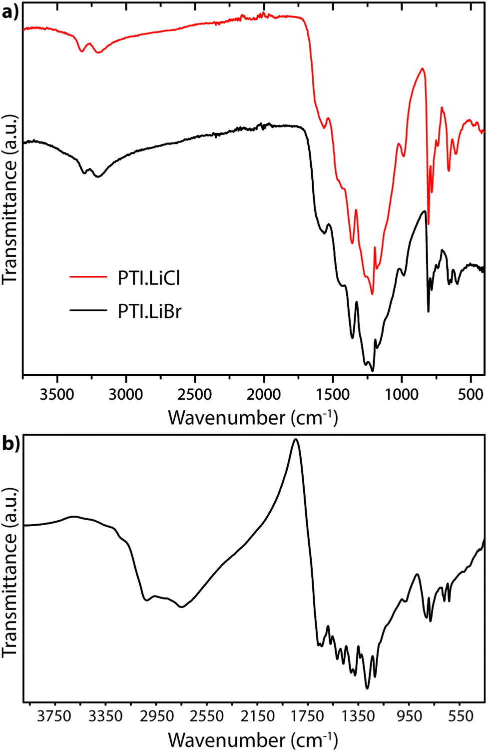 | ||
| Fig. 18 FTIR powder transmission spectra for (a) PTI·LiCl and PTI·LiBr (b) PTI·HCl.64 | ||
The IR spectra of PTI·LiCl and PTI·LiBr samples are nearly identical in the N–H stretching region, and they both lack the very low frequency band observed for PTI·HCl (Fig. 18a). That must be due to the replacement of all or part of the additional H+ species around the C12N12 rings attached to bridging –NH– groups by Li+ cations.26,27 Two well defined peaks occur at 3321 and 3195 cm−1 for PTI·LiCl, and at slightly lower wavenumber values for the PTI·LiBr compound, due to the remaining –NH– linkages between triazine units within the planar PTI (poly-C2N3H) layers.
The only gCN materials have been shown to contain no N–H stretching features in their IR spectra to date are the triazine-based nanocrystalline g-C3N4 structures produced by CVD techniques.24 The data present a broad absorption band extending between approximately 1150–1650 cm−1 that can be assigned to in-plane C–N stretching and bending vibrations of the graphitic layers. Our DFT calculations performed for a single layer of this structure predict three strong peaks spanning the range of the experimentally measured spectrum (Fig. 19a).24 The broad absorption band that is observed experimentally could arise from stacking disorder combined with different degrees of layer buckling within the thin films of the nanocrystalline material. The IR spectra of bulk crystalline TGCN reported by Algara-Siller et al. contain additional features that are most likely due to contributions from PTI·LiCl that formed a main product of the synthesis reaction in molten salt media.23
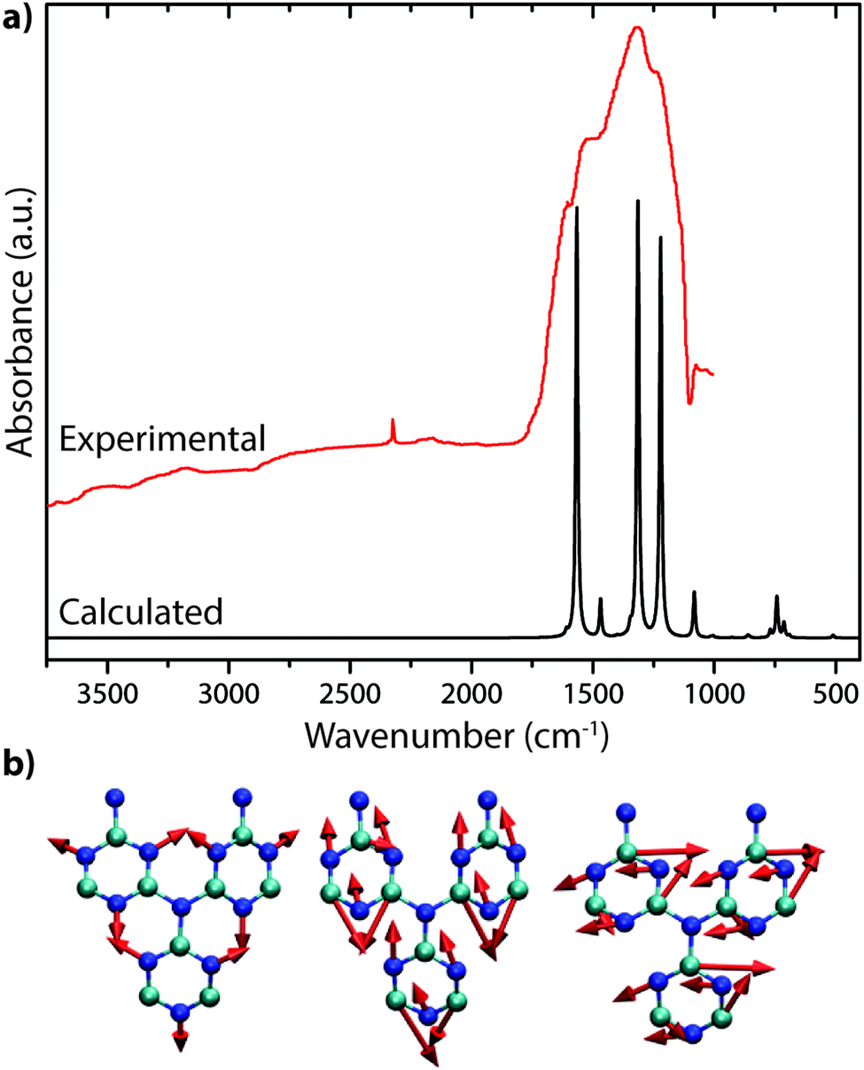 | ||
| Fig. 19 IR spectra of C3N4: (a) IR spectrum for triazine based C3N4 from Kouvetakis et al. (Reprinted (adapted) with permission from ref. 24. Copyright (1994) American Chemical Society). This includes a DFT calculated spectrum based on their proposed structure. (b) Selected normal mode displacement patterns from DFT calculations for one layer of triazine-based g-C3N4 showing the symmetric ring breathing mode that is expected to give rise to strong Raman activity near 1000 cm−1 (left), along with two in-plane bending vibrations expected to occur near 1550–1600 cm−1 (right). | ||
The IR spectra of polymeric CxNyHz materials formed by thermolysis reactions from precursors typically exhibit a large number of relatively sharp peaks extending throughout the 700–1700 cm−1 region. These can be assigned by analogy with organic molecular compounds as due to C–N stretching and NCN/CNC bending vibrations, along with δ(NH2) deformation modes that are likely to be mainly concentrated in the higher frequency range, between 1550–1700 cm−195,96 (Fig. 17). The nature of these vibrations has been studied using both ab initio and empirical force field calculations, as well as by reference to compounds such as s-triazine (C3N3H3), melamine (C3N3(NH2)3) and melem (C6N7(NH2)3).58,95,97,98
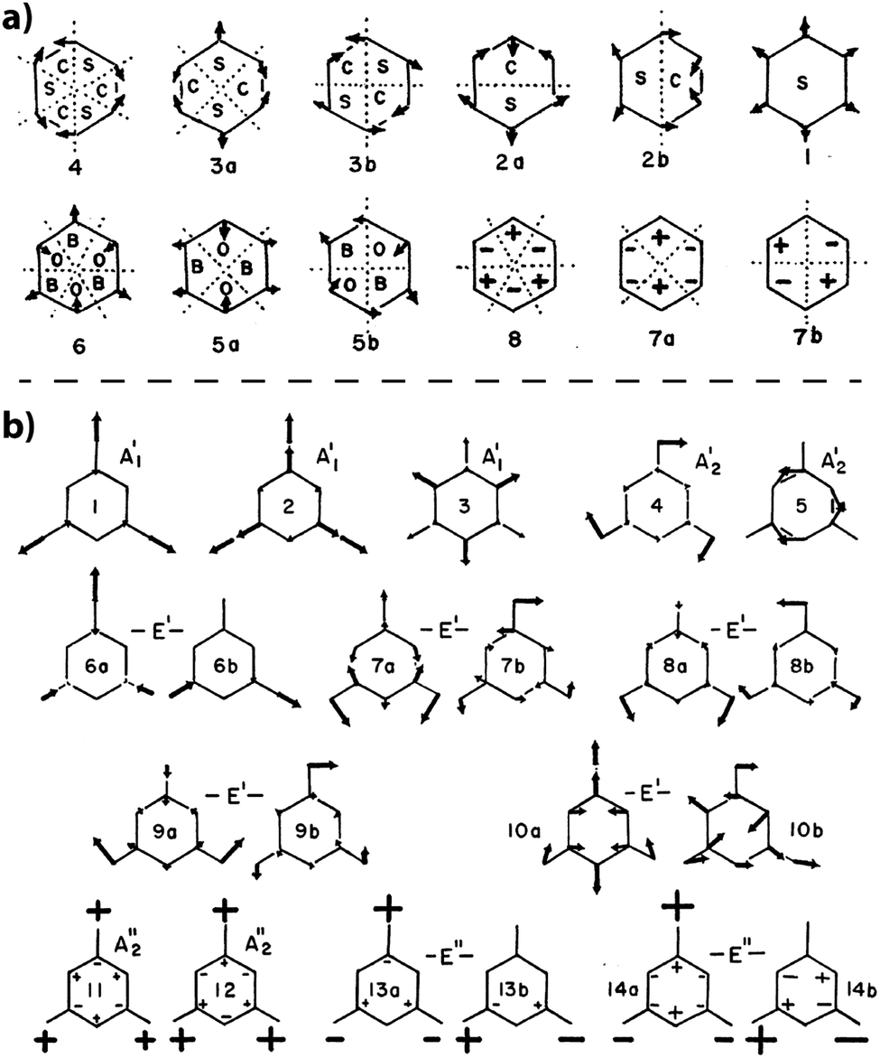
The simplest molecular compound containing the C3N3 ring is s-triazine (C3N3H3), that was first studied in detail by Larkin et al.97 Because H is linked to C rather than N atoms, it is only of limited use in understanding the vibrations of solid state and polymeric gCN structures. However, the terminology applied to its vibrational analysis is typically used to describe the vibrational mode assignments for the condensed carbon nitride phases.21,95,99 Larkin et al. based their assignments on those for benzene, in terms of the normal modes for a planar six-membered ring.97 The ring was split into “quadrants”, “sextants”, hemicircles and whole-ring vibrations (Fig. 20a).97,100 That general description was then extended to describe the 21 normal vibrational modes of s-triazine (Fig. 20b). Larkin et al. noted that “sextant” ring CN stretching along with NCN bending contributions should occur between 950–1000 cm−1, with out-of-plane bending vibrations appearing near 750 cm−1. Of particular interest are the IR peaks at 748 and 675 cm−1 that were assigned to deformation vibrations of the C3N3 ring. Characteristic sharp IR and Raman peaks that appear throughout these regions for both triazine- and heptazine-based molecules and gCN structures might be assigned to similar motions. Wang et al. used a related scheme to assign analogous peaks in the IR and Raman spectra of melamine (C3N3(NH2)3), although significant contributions from –NH2 torsional components were also suggested to be associated with the vibrational modes throughout this region.101 The results of detailed IR and Raman studies of melamine are summarized by Mircescu et al.102
 | ||
| Fig. 20 (a) Normal mode description for a 6-membered ring structure from Larkin et al. indicating the characteristic atomic displacement patterns and numbering scheme (b) normal mode patterns for s-triazine from Larkin et al. Reprinted from ref. 97 Copyright (1999), with permission from Elsevier. | ||
In their study of crystalline melem (C6N7(NH2)3) containing the cyameluric (heptazine) core, Jürgens et al. correlated distinct peaks at 1606, 1496, 1304 and 802 cm−1 (Fig. 17) with similar features in the spectrum of chlorinated C6N7Cl3 (at 1610, 1505, 1310 and 825 cm−1), indicating that they correspond to characteristic modes of the heptazine ring structure, and not to N–H bending vibrations.58 Kroke et al. likewise suggested that the presence of IR peaks at 1608, 1529, 1359 and 818 cm−1 were characteristic of heptazine-based structures, based on studies of related molecular compounds.103
Lotsch et al. used IR spectroscopy to study the formation of melem from melamine by thermal condensation reactions.104 Following treatment at 500 K they observed a strong absorption band at 1610 cm−1 associated with the appearance of melem. This process also resulted in splitting of the 1475 cm−1 band of melamine into a doublet, along with appearance of a weaker IR peak at 1107 cm−1. In another study, Lotsch et al. noted that nanocrystalline melon that is built from ribbons of linked heptazine units contains prominent IR features at 1206, 1235 and 1316 cm−1.21 These peaks were correlated with characteristic modes associated with C–NH–C units, as found in melam [C3N3(NH2)2]2NH (Fig. 17).26 During formation of polymeric CxNyHz samples from melamine/DCDA mixtures at temperatures between 550–650 °C,77 we observed characteristic features occurring at 1626, 1550, 1396 cm−1, along with a sharp peak at 808 cm−1, that likewise indicate the presence of heptazine-based structures (Fig. 17).
A sharp IR peak occurring near 800 cm−1 was initially assigned to a “sextant” out-of-plane bend according to the description of the C3N3 ring vibrations for molecular s-triazine by Larkin et al.97 However, a similar peak is observed for molecular compounds and polymeric gCN materials that are now known to be based on heptazine motifs.21,50,58,83,97,105–107 Wang et al. assigned sharp IR peaks at 748 and 675 cm−1 to out-of-plane and in-plane bending vibrations of the C3N3 ring in the IR and Raman spectra of melamine (C3N3(NH2)3), while peaks at 810 cm−1 and 798 cm−1 occur for melam and melem that both contain the C6N7 heptazine species (Fig. 17).95 During thermal condensation of melamine to form melem, Lotsch et al. noted that the sharp peak near 800 cm−1 remained present throughout the polymerization process.104 Sharp IR peaks also appear in the same region for PTI·LiCl and PTI·LiBr compounds, that are known to be built only from triazine ring units (Fig. 18). Additionally, Antonietti et al. proposed that an IR peak at 1350 cm−1 in spectra of PTI compounds synthesized in ZnCl2, LiCl/ZnCl2 and KCl/ZnCl2 molten salt media indicated that they were built from triazine rather than heptazine groups.108 Bian et al.109 deposited yellow-brown gCN films derived by condensation from melamine heated to 500 °C in air on fluorinated tin oxide glass. The resulting films showed a weak, broad X-ray feature at 27.8° 2Θ (Cu Kα) but the data could not reveal any information on the 12–14° 2Θ region that might indicate formation of heptazine- vs. triazine based structures.20,52 They then carried out ab initio (DFT) calculations based on polyheptazine units to help interpret the IR spectra of the films, noting that a peak observed at 823 cm−1 could correspond to the collective “wagging” mode of the model oligomeric structure calculated at 818 cm−1, and that a second feature observed at 605 cm−1 might be due to N–H deformation vibrations.109
In Fig. 21 we compare the IR spectra of a typical polymeric CxNyHz material prepared by thermolysis of a melamine/DCDA mixture that has a structure related to Liebig's melon, based on partly condensed polyheptazine units, and crystalline layered PTI·LiCl formed by linked triazine groups. We have highlighted specific features that are found in each or both solid state materials, or in the molecular compounds melamine and melem that provide models for the s-triazine vs. heptazine core units. Obtaining definitive evidence for the presence or absence of particular ring motifs is not obvious at our present state of understanding, however there appear to be sufficient systematic differences between the two types of structure that further systematic calculations using ab initio theoretical methods for hierarchies of structural models could enable use of FTIR spectroscopy as a powerful tool for distinguishing different states of gCN polymerization.
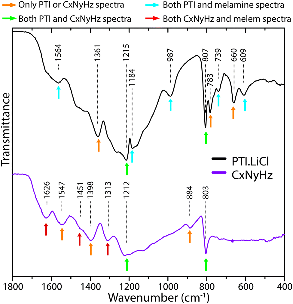 | ||
| Fig. 21 Comparison of IR spectra for polymeric/graphitic CxNyHzvs. PTI·LiCl, indicating characteristic peaks found in each type of structure. | ||
Raman spectroscopy constitutes a complementary technique for studying the vibrational properties of molecules and solids. However, fewer Raman data have been reported for polymeric or graphitic carbon nitride materials, mainly because of interference from strong fluorescence background signals when the spectra are excited using visible light lasers that are typically available. However, the Raman spectra provide additional data especially in the low wavenumber range that is not readily accessible to conventional laboratory IR techniques, and the complementary vibrational modes observed due to symmetry considerations can help complete the structural elucidation process. However, for more condensed gCN materials, the Raman data become dominated by solid state excitation and resonance effects, including electron–phonon coupling.64
Jürgens et al.58 reported Raman data for the molecular crystal melem using near-IR (1064 nm) laser irradiation and Fourier transform (FT) acquisition techniques. Quirico et al. also recorded Raman spectra for polymeric CxNyHz compounds prepared by gas phase reactions as models for the atmospheric “tholins” of Titan, as well as melamine, s-triazine and PTI·HCl, using UV (244, 229 nm) as well as near-IR (1064 nm) excitation (Fig. 22).110 The Raman data for the molecular compounds exhibited series of sharp peaks, but the spectra for the highly condensed materials more closely resembled the broad features found in the 1350–1700 cm−1 region and assigned to the “G” and “D” bands of disordered graphite, that are best interpreted using a solid state approach to the phonon dynamics and excitation profiles.
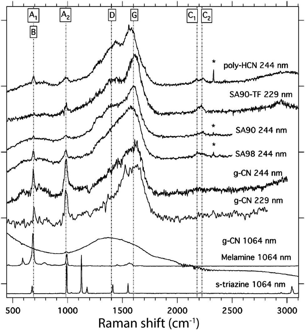 | ||
| Fig. 22 Raman spectra of various polymeric to molecular CxNyHz structures. Reprinted from ref. 110 Copyright (2008), with permission from Elsevier. | ||
Ferrari and colleagues have summarized the use of Raman spectroscopy to study the phonon physics and optoelectronic coupling in a wide range of carbon-based materials included N-doped graphite and graphene.111–113 Single crystalline graphite exhibits a strong sharp Raman peak at 1578 cm−1 due to in-plane C–C stretching vibrations of the sp2-bonded structure at the Brillouin zone centre (Γ point), generally termed the “G band”, along with broader second-order (2D) features maximized near 2700 cm−1.112–114 Disordered graphites exhibit various states of layer stacking disorder and buckling depending on the mode of preparation, that cause broadening and a shift to higher wavenumber in the G band, along with appearance of a second “D band” feature near 1350 cm−1.112–115 At the same time, the 2D feature typically moves upwards to wavenumber values near 3000 cm−1. The analysis has been extended to lower-dimensional materials including graphene and carbon nanotubes.112,116,117 Due to electron–phonon coupling, the features change in appearance and relative position as a function of incident laser wavelength and resonance Raman effects.112 Similar signatures have been recorded for N-doped CNx materials, where it has been noted that that the apparent correspondence between peaks observed at similar wavenumber values in Raman and IR data can be misleading.118 Some interpretations of the detailed molecular structure have also been proposed. The UV-Raman spectra for PTI·HCl as well as other gCN materials exhibited sharp Raman peaks at 980 and 690 cm−1 that were assigned to symmetric breathing motions associated with the triazine rings, by comparison with the peaks present in the 1064 nm Raman spectra of s-triazine and melamine.110 However, the Raman spectrum for PTI·HCl obtained using the same near-IR excitation showed only a broad band extending between 1000–2000 cm−1. That result was interpreted in terms of loss of phonon coherence and spectral broadening for longer excitation wavelengths that probed more extended vibrational states, compared with more localized vibrational modes observed using UV excitation.64 Although Raman scattering is commonly used to complement IR spectroscopy in structural analysis studies of molecular compounds and solid state materials, the fact that electronic transitions associated with both localized and extended states occur throughout the visible range for gCN compounds and enter into resonance with exciting laser wavelengths means that interpretation of the data is more subtle rather than simply giving information on the molecular structure. As we begin to better understand the optoelectronic properties of gCN materials, the Raman data will help us develop better control and optimization of functional properties related to light harvesting, luminescence and photocatalysis, as well as optically assisted routes to synthesis and functionalization.
3.5. Solid state NMR studies
High-field solid-state NMR, involving magic angle spinning (MAS) and multiple pulse excitation–acquisition techniques, represents a powerful family of methods used to obtain detailed structure information on molecular and solid state compounds. Because the primary elements contained within the various carbon nitride materials all represent NMR active nuclei (13C, 14N, 15N, 1H, 7Li etc.),21,27,58,119 it could be expected that this approach might be readily applied on a routine basis to provide unambiguous information on the structural units present. However, this is only partly the case because of the characteristics of the nuclei involved and the constraints imposed by the NMR experiment. Although the spin-1/2 13C nucleus is only present at 1.1% natural abundance,120 it is readily observed by modern instruments in non-enriched samples.21,26,27 The sensitivity can be enhanced by cross-polarization (CP) techniques as 1H resonances are excited and the spin polarization is transferred to 13C nuclei located close to the 1H sites.58,119 These spin transfer dynamics provide useful additional information on 1H⋯13C separations within the structure. 14N is naturally present in high abundance (99.6%), but it is a spin-1 quadrupolar nucleus resonating at low frequency (36 MHz at 11.7 Tesla),120 and it is difficult to observe in practice. Instead, the spin 1/2 15N nucleus (51 MHz at 11.7 T) is usually targeted, although it is only present at 0.37% natural abundance.120 Its detection is typically enhanced by 1H–15N CP studies for non-enriched samples, but that procedure preferentially highlights those nuclei that lie close to 1H centres. Several key studies have used samples isotopically enriched in 15N to carry out detailed structural studies of CxNyHz compounds.21,26,27 These results have been of critical importance for establishing the local structural arrangements in key gCN materials, but this approach is unlikely to be applied generally for routine characterization of samples.:1 ratio, at 166 and 159 ppm respectively. These peaks were assigned to “α-type” C atoms surrounding the C12N12 ring void, bonded to the in-ring nitrogen atom and unprotonated, and “β” C atoms bonded to the protonated in-ring nitrogen atoms. The 159 ppm peak was observed to be broader and it had an unresolved shoulder at ∼156 ppm, indicating small differences in the local 13C environments. The 13C NMR spectrum of TGCN exhibits a single broad line, peaking at approximately 160 ppm, but extending throughout the 175–145 ppm range.23
13C NMR studies of melamine and melem have indicated that resonances at 164–169 ppm should be assigned to C atoms bonded to the external –NH2 groups, whereas peaks at 155–156 ppm are due to the sp2 species linked trigonally to three N atoms within the triazine or heptazine rings and not directly connected to any N–H functional groups.58 These assignments appear to contradict the conclusions of Zhang et al. noted above, and this question has not yet been resolved in the literature.25 We also note that other, presumably triazine-based, carbon nitride materials that reportedly contain N–H species, exhibit both a main 13C peak at 169 ppm with shoulders at 165 and 156 ppm. Sehnert et al. carried out ab initio calculations to predict and analyze the 13C and 15N chemical shift positions for different C and N sites in various C,N-containing molecules and molecular fragments.121 Melamine spectra calculated for “planar” vs. “non-planar” geometries showed 13C δiso resonances occurring between 170–175 ppm. For melem a second resonance emerged at a lower δiso chemical shift, between 160–170 ppm (calculated). These were identified with “outer” (Co) and “inner” (Ci) carbon atoms contained within the heptazine unit, respectively.
Theoretically computed NMR shifts typically exhibit systematic differences from experimental values that can be accounted for by establishing a scaling protocol by comparison with data for known molecules. In our studies at UCL, we investigated this using CASTEP (version 5.5),122 in which fully converged geometry optimizations were first carried out using PBE exchange–correlation functionals and ultrasoft pseudopotentials. Values for the NMR shielding tensor elements were obtained using the GIPAW method.123,124 Calculations of the 13C and 15N standards TMS and nitromethane (CH3NO2) gave isotropic shielding parameters σiso (13C) = 178.2 ppm and σiso (15N) = −165.5 ppm, which were used to establish 13C and 15N chemical shift parameters (δiso) for various C,N-containing molecules and fragments for comparison with experiment. Comparing experimental vs. calculated 13C σiso values for molecules ranging from hydrocarbons to melamine and triazine provided linear relationships leading to the scaling factor:
| δiso (13C, scaled) = 0.9295 δiso (calc.) − 0.8771 |
A similar approach applied to 15N chemical shifts provided the scaling equation:123
| δiso (15N, scaled) = 0.9114 δiso (calc.) − 0.16613 |
If this scaling is applied to the DFT calculation results of Sehnert et al.121 this leads to an estimation of 13C δiso values of ∼150 ppm for the Ci atoms and ∼162 ppm for the Co atoms of heptazine-derived g-C3N4. The experimental 13C NMR peak for the triazine-based PTI·HCl compound reported by Zhang et al.25 had δiso = 166 ppm and was assigned to “α-type” C atoms that were not associated with N–H protonation, whereas a second peak at 159–156 ppm was suggested to represent C atoms close to the bridging –NH– or –NH2+– groups. It therefore appears that assignment of the 13C NMR signals of the different gCN materials requires further systematic investigation, combining experimental determinations with theoretical predictions.
During their extensive structural investigations of melon, melem and other gCN materials, Lotsch,21 Senker27,58 and co-workers prepared 15N-enriched (by ∼25%) compounds to carry out detailed series of multiple pulse, 1H–15N CP and magnetization transfer experiments to characterize the local structural environments around N atoms. The results led to significant new understanding of the polymeric CxNyHz structures, that were shown to be based on heptazine motifs, leading to ribbon-like and potentially layered structural units.21,58 One main result was identification of an isolated peak at −225 ppm (relative to nitromethane) with the central (Nc) nitrogen atom of the heptazine core unit. A group of signals extending between −175 to −180 ppm were identified as due to “Ntert” species bonded to –C(NH) and –C(NH2) units, whereas others at larger δiso values (−230 to −270 ppm) were assigned to N atoms directly bonded to hydrogen (NH, NH2 species). Those assignments generally agreed well with the theoretical predictions made by Sehnert et al.121 The N–H species typically give rise to the largest (most negative) chemical shifts, and so these could be used as diagnostic of the presence of significant N–H content within the samples. In their study of TGCN, Algara-Siller et al. noted two asymmetric peaks occurring at −210 and −160 ppm, referenced relative to glycine (that itself appears at 33 ppm relative to NH3 liquid, and at 381 ppm relative to nitromethane).23,125 The peaks were assigned respectively to N atoms contained within the C3N3 rings (199 ppm) and the bridging N atoms between triazine units (128 ppm). These authors did not comment on the fact that their 1H–15N CP MAS NMR spectra were obtained for a nominally H-free g-C3N4 material.
4. Carbon nitrides for energy provision and sustainability applications
Carbon nitride materials are currently being proposed, examined and developed for technological applications, especially in areas of catalysis, energy provision and sustainability.5 However, optimizing the materials and their in-device performance relies critically on understanding and controlling the properties through structural studies on an atomistic scale. Here we briefly present the projected use of carbon nitrides for several key applications, highlighting the structure-performance characteristics that have been determined and that must be refined in future investigations.4.1. Carbon nitrides as semiconducting materials and photocatalysts
One of the targeted outcomes for a successful photocatalyst is its ability to efficiently capture light from the Sun within the visible range at the Earth's surface, and thus enable splitting of Earth-abundant water into its elemental constituents (i.e., perform the reaction 2H2O → 2H2 + O2) to provide hydrogen fuel for energy production via its exothermic recombination with oxygen to reform water.2,10,126 Intense activity began in this area with the discovery that nanocrystalline anatase-structured TiO2 could perform this function under UV illumination,127 followed by many suggestions for doped TiO2 and other alternative materials to improve the efficiency, that could be extended into the visible range.Recent interest in carbon nitride materials has largely arisen from identification of their photocatalytic properties, that are either intrinsic or following doping with co-catalysts such as nanocrystalline Pt or RuO2, to enable water splitting and/or methanol reduction reactions under UV-visible light irradiation. These useful properties are enabled by their wide semiconducting bandgaps, that are ideal for solar energy harvesting, and the position of their HOMO and LUMO levels, that straddle the oxidation and reduction potentials of water (Fig. 23a).2,5,10,128 The first report of gCN being used for photocatalytic water splitting, that has played a significant role in reinvigorating modern interest in carbon nitrides, was published by Wang et al.2 (Fig. 1). These researchers produced heptazine-structured polymeric CxNyHz compounds formed by heating cyanamide (DCDA) to temperatures between 400–600 °C, although the products of the reactions were incorrectly described as “g-C3N4”. They showed that over a period of 25 hours up to 100 μmol H2 could be evolved from “unmodified g-C3N4” and 260 μmol H2 for “g-C3N4 decorated with 3 wt% Pt co-catalyst” using triethanolamine as electron donor under visible light (of wavelength > 420 nm) under a 300 W lamp.2 The quantum efficiency of both of these catalysts was low (<0.1% with irradiation of 420–460 nm). Other researchers have found similar results.5,10,126 Despite much work in this area, most gCN compounds investigated to date do not show high intrinsic photocatalytic activity in the visible wavelength range, unless co-catalysts such as Pt or RuO2 are introduced, and sacrificial electron donors or acceptors (e.g. methanol) are usually present.126 Care must also be taken when interpreting the results of these photocatalytic experiments as most utilize high-power (300 W) illumination sources, with or without inclusion of UV wavelengths, that do not always reflect the actual solar irradiation conditions at the Earth's surface.129 Comparative reviews of photocatalytic efficiencies of various materials as well as projected future targets have appeared recently.126,128 Overall, the photocatalytic performance of polymeric to graphitic CxNyHz materials remains substantially lower than that achieved by other materials, although there is obvious potential for future development to be derived from systematic understanding of the structure–composition–properties relationships of the light element compounds.130
 | ||
| Fig. 23 Semiconducting properties of carbon nitrides. (a) Band-edge positions of ‘g-CN’ and titanium dioxide relative to the energy levels of H+/H2 and H2/H2O in water at pH = 0. Reproduced from ref. 128 with permission from the PCCP Owner Societies. (b) UV-vis diffuse reflectance spectra of gCNs prepared at different temperatures. Reprinted (adapted) with permission from ref. 77. Copyright (2013) American Chemical Society. (c) Calculated electronic density of states for conductive C (graphene) and a selection of three representative layered carbon nitride structures. Adapted from ref. 6 under the terms of the Creative Commons Attribution License (CC BY). | ||
The semiconducting bandgaps of gCNs are determined by π–π* transitions of the heterocyclic aromatic constituents between around 2.5–2.8 eV, leading to optical absorption beginning in the violet-blue range of the visible spectrum.2,77 This causes the yellow/brown coloration typically exhibited by gCN materials,77 while also resulting in their poor electronic conductivity.14 The optical absorption color evolves from pale yellow to deep brown as the degree of polymer condensation increases with cross-linking and loss of terminal –NH2 components. As condensation occurs, the polytriazine and polyheptazine structural units become increasingly buckled and non-bonded electrons based on the N atoms can increasingly undergo normally non-allowed n–π* transitions, giving rise to absorption features near 500 nm and an apparent redshift in the absorption edge that lead to a brown color (Fig. 23b).77 The ability to tune the bandgap of gCN materials is of particular interest for photocatalytic applications.77,131
One significant recent development in the use of gCN materials for photocatalysis is the discovery by Lau et al.130 that defects with particular functionalities play a crucial role in the photocatalytic activity of carbon nitrides. By studying the structure-hydrogen evolution activity relationships of a range of molecular or polymeric carbon nitride analogues (methanol electron donor, Pt co-catalyst, 300 W xenon lamp, 2000 nm > λ > 200 nm), including some of those described here (melem, cyameluric acid, potassium cyamelurate and melon), they were able to determine the cyanamide moiety to be photocatalytically important. By applying this knowledge to the design of a melon-based photocatalyst, with increased cyanamide functionalities, they were able to demonstrate greatly improved hydrogen evolution rate and apparent quantum efficiency (at 400 nm) over pure, untreated melon.130 This approach is an example of how improved understanding of the carbon nitride compositional-structural relationships can directly impact on development of their functional applications.
4.2. Carbon nitrides as energy storage materials
Lithium ion battery (LIB) anodes are typically formed from graphitic carbon that can theoretically result in the stoichiometric intercalation compound LiC6, giving a maximum capacity of 372 mA h g−1.132 DFT calculations have predicted that idealized models of layered carbon nitride structures can have a much higher theoretical Li capacity, extending up to 524 mA h g−1 (Li2C3N4),133 due to additional storage sites derived from Li+ ions residing in intra-layer voids as well as intercalated between the layers. Veith et al. used solid-state lithiation techniques to achieve carbon nitride materials containing 10.6 at% Li (reported from XPS analysis) for a “disordered C3N4”, and 12.1 at% for a “crystalline C3N4” material. Although not precisely defined in the report, the latter was most likely a triazine-based compound with a structure related to PTI·LiCl.15 Upon incorporation, the Li selectively reacted with the quaternary N–C3 environments, which reduced the crystallinity of the carbon nitride. It has also been reported that ∼3 wt% Li can be taken up by amorphous gCN, using liquid ammonia based lithiation.134 Such results indicate that CxNyHz materials could potentially be developed as useful materials for high-capacity anodes for LIB or sodium ion batteries (NIBs).13–15,93 A report by Yang et al. examined a carbon nitride that was suggested to be a layered triazine-based material, but was more likely an amorphous, heptazine-based structure.93 Their first cycle capacity was adequate (>130 mA h g−1), but there were significant irreversible capacity losses on subsequent cycling (the second cycle capacity was only ∼8% of that of the first, and after ∼20 cycles it was approximately zero). This result was later confirmed by Veith et al. who observed that the electrochemical capacity in their anode primarily resulted from the carbon black component they added to boost the electronic conductivity.15 Miller et al. carried out a systematic investigation of this problem using composite gCN/conductive graphite anodes and found a clear correlation between the Li+ capacity of the composite and the electrode resistivity.14 It is now clear that the electrical resistance of the gCN material is a major factor limiting Li+ uptake, and the incorporation of electronically conducting additives has so far been insufficient to overcome this barrier.Most recently, Hankel et al. used a combination of DFT calculations and experiment to further investigate Li+ and Na+ uptake into gCN materials.13 Results of this work supported the previous theoretical predictions that the carbon nitrides should have a large uptake capacity for Li+, but they showed that this process is irreversible, due to Li+ favouring the pyridinic nitrogen sites, that then also weaken the C3N bonds. In their work, Hankel et al. also examined the possibility of using gCN as an NIB anode.13 The Na+ storage performance was found to be just as poor as that recorded for LIB anodes, with a reversible capacity lower than 25 mA h g−1, much of which could be attributed to the conductive carbon additive. The overall conclusion is that, although the introduction of large amounts of nitrogen into graphitic anode materials to create additional potential storage sites within and between the layers has been predicted to boost the theoretical capacity,135 the large semiconducting band gap and bonding structure gCN materials means they are likely unsuitable for use in their current form. It has been proposed that by reducing the content of N–C3 sites, while maintaining the pyridinic ones, carbon nitrides might yet be designed that would lead to viable LIB/NIB anode materials,13 and this could be a useful avenue to explore in future work.
4.3. Carbon nitrides as catalysts and catalyst support materials
The significant mechanical, chemical and thermal resilience of carbon nitrides, combined with their surface and intralayer chemical reactivity, has led to possibilities for developing carbon nitride materials for catalysis applications, either intrinsically or when decorated with metal/metal oxide NPs. gCN materials have been shown to act as metal-free heterogeneous catalysts, relying on the intrinsic abundance of Brønsted acid and Lewis base functionalities that provide catalytically active sites, while the nature of gCN materials and their surfaces that makes them amenable to chemical modifications including doping, protonation and molecular functionalization, can be exploited to improve performance and selectivity.9,10,12 They are also being developed as active NP support materials that survive under harsh operating conditions.One main application of NP catalysts supported on gCN Is in the area of fuel cell devices, especially polymer electrolyte or proton exchange membrane fuel cells (PEMFC), as well as water electrolyzers.6 The success of gCN materials in these applications is generally due to their wide electronic band gaps that bracket the H+/H2 and O2/H2O potentials and make corrosion of the C–N backbone thermodynamically unfavourable under electrochemical operation.6 Metal or metal oxide NPs deposited onto the gCN are also less prone to the effects of poisoning and agglomeration caused by etching of traditional carbonaceous support materials. In one study, Kim et al.136 examined Pt/Ru NPs supported on gCN to show that in a direct methanol fuel cell (DMFC) device the electrocatalyst exhibited 78–83% higher power density than the same catalyst deposited on carbon black.136 In another investigation, Mansor et al.7 prepared Pt NPs supported on gCN and PTI materials and demonstrated enhanced electrochemical stability over that of traditional carbon black during accelerated corrosion testing. In particular, Pt NPs deposited on the highly crystalline PTI·LiCl showed excellent durability and this catalyst-support combination was found to have superior intrinsic methanol oxidation activity.7 However, as for the LIB applications described above, a main limiting factor to the use of gCNs for these catalyst support applications derives from their low electronic conductivity, that particularly affects kinetically slow processes like the oxygen reduction reaction (ORR). If the gCN materials are embedded within a conductive matrix, e.g. graphene or reduced graphene oxide (rGO), these hybrid systems are shown to perform significantly better.6,137 They might therefore lead to useful catalyst support systems that provide extended lifetime at comparable performance levels to existing material combinations. These applications are currently under development, but will require expanded understanding of the physical and chemical properties of the gCN surfaces and their interaction with catalyst NPs, as the reactions proceed under real operating conditions.6
5. Conclusions and perspectives
The discovery of carbon nitride materials began as modern chemical science was just beginning to emerge. Since that time a diverse family of materials has been developed with potentially useful physical and chemical properties leading to important functionality for applications ranging from catalysis, photocatalysis and photoluminescence, to energy storage and conversion. An unfortunate practice has developed within recent literature to term all such materials “g-C3N4”, or graphitic carbon nitride with a precise and ideal stoichiometry, when in fact most of the materials produced are likely to have polymeric structures related to that of Liebig's melon with a limiting composition near C2N3H. We propose instead use of a hierarchical scheme for naming these materials and compounds. All of the materials produced with large N:C ratios that are likely to contain layered elements within their structures should be termed “gCN” or “GCN”. To designate more specifically the more or less condensed polymeric structures formed by thermolysis or other reactions from precursors, we should implement “gCN(H)” or “pCN(H)” as a general term, to denote the large and essential H component within the structures, that has implications for the physical properties and functionality. Crystalline layered compounds based on polytriazine imide-linked layers with intercalated Mn+ and Xn− species are PTI·MX materials, with specific properties related to their intercalation chemistry and redox behavior. Finally, the term “g-C3N4” should be reserved for those layered compounds with a stoichiometry close to the ideal value. That class includes both nanocrystalline materials produced by CVD techniques and bulk triazine-based graphitic carbon nitrides (TGCN), as well as the hypothetical heptazine-based equivalent (HGCN). Adopting such a hierarchical naming scheme would help avoid confusion in the literature, when attempting to match the chemical and structural characterization of the compounds with their physical properties and anticipated functionality. It will also help in more rational design of the synthesis approaches, as new gCN materials are optimized and created for existing and emerging applications.
Most of the gCN materials that have been investigated are polymeric CxNyHz structures related to Liebig's melon, containing ribbon-like heptazine units linked by –NH– and sp2-bonded N atoms and terminated laterally by –NH2 groups. A smaller family of gCN materials is constituted by the layered PTI materials, that contain Li+, Cl−, Br− and other ions intercalated within or between the graphitic sheets with approximately C2N3H composition, giving rise to new ion exchange and intercalation chemistries as well as modifying the optoelectronic and semiconducting properties. True g-C3N4 materials have only been reported in two instances, as nanocrystalline thin films produced by CVD techniques, or as bulk TGCN crystals as a by-product from PTI·LiCl or PTI·LiBr syntheses in molten salt media.23,24 These structures are shown to be derived from condensed triazine units, rather than the linked heptazine (HGCN) motifs predicted by DFT calculations to constitute the most stable polymorph of g-C3N4. Achieving and demonstrating the existence of such heptazine-based graphitic structures represents a major challenge for the field. Understanding the structures and physical properties of different types of gCN materials is progressing rapidly due to the application of advanced techniques for chemical and physical characterization combined with ab initio theoretical methods. However, much work remains to be done in order for us to fully understand and provide the necessary tunability and control over their physical properties. All of these compounds exhibit many possibilities leading to useful functional behavior. They contain exchangeable N–H and Lewis-basic N: sites for catalysis and attachment of catalytically active NPs on their surface, while maintaining a high resistance to adverse chemical and physical conditions. They have a wide bandgap extending into the visible range resulting in photocatalytic activity. In addition, they provide enhanced storage sites for Li+ or Na+ for battery applications, although the poor electronic conductivity for gCN materials counteracts that possibility. All of these useful and intriguing results indicate that carbon nitride materials indeed form a class of emerging materials for advanced technological applications. However, their structures and compositional properties must be properly evaluated and reported in order to define and target the research that is needed to predict and optimize their behavior. The results reviewed here show the great potential of this unique family of materials for a wide range of modern applications. Through their continued development, including the scalable production of new technological inks and 3D porous networks, the preparation of new families of integrated catalysts containing protective N-rich regions and selective functionalization of materials to promote specific activity (e.g. visible light absorption), it is likely that carbon nitrides will become increasingly important in future technologies. However, it will be critically important to the industrial uptake of these materials to also develop efficient, low-cost and truly scalable processes for their synthesis, exfoliation and deposition, especially via drop-in technologies that will enable new developments to rapidly enter the commercial marketplace.
Acknowledgements
Our work on carbon nitride materials has been supported by the EPSRC (EP/L017091/1) and the EU Graphene Flagship grant agreement No. 696656 – GrapheneCore1. Additional support to advance the science and technology of these materials was also received from the UCL Enterprise Fund and the Materials Innovation Impact Acceleration funding enabled by the UK EPSRC.References
- K. Schwinghammer, M. B. Mesch, V. Duppel, C. Ziegler, J. Senker and B. V. Lotsch, J. Am. Chem. Soc., 2014, 136, 1730–1733 CrossRef CAS PubMed.
- X. Wang, K. Maeda, A. Thomas, K. Takanabe, G. Xin, J. M. Carlsson, K. Domen and M. Antonietti, Nat. Mater., 2009, 8, 76–80 CrossRef CAS PubMed.
- F. Su, S. C. Mathew, G. Lipner, X. Fu, M. Antonietti, S. Blechert and X. Wang, J. Am. Chem. Soc., 2010, 132, 16299–16301 CrossRef CAS PubMed.
- E. J. McDermott, E. Wirnhier, W. Schnick, K. S. Virdi, C. Scheu, Y. Kauffmann, W. D. Kaplan, E. Z. Kurmaev and A. Moewes, J. Phys. Chem. C, 2013, 117, 8806–8812 CAS.
- F. Kessler, Y. Zheng, D. Schwarz, C. Merschjann, W. Schnick, X. Wang and M. J. Bojdys, Nat. Rev. Mater., 2017, 2, 17030 CrossRef CAS.
- N. Mansor, T. S. Miller, I. Dedigama, A. B. Jorge, J. Jia, V. Brázdová, C. Mattevi, C. Gibbs, D. Hodgson, P. R. Shearing, C. A. Howard, F. Corà, M. Shaffer, D. J. L. Brett and P. F. McMillan, Electrochim. Acta, 2016, 222, 44–57 CrossRef CAS.
- N. Mansor, A. B. Jorge, F. Corà, C. Gibbs, R. Jervis, P. F. McMillan, X. Wang and D. J. L. Brett, J. Phys. Chem. C, 2014, 118, 6831–6838 CAS.
- V. Di Noto, E. Negro, K. Vezzù, F. Bertasi and G. Nawn, Electrochem. Soc. Interface, 2015, 24, 59–64 CrossRef CAS.
- A. Thomas, A. Fischer, F. Goettmann, M. Antonietti, J. O. Muller, R. Schlogl and J. M. Carlsson, J. Mater. Chem., 2008, 18, 4893–4908 RSC.
- Y. Wang, X. Wang and M. Antonietti, Angew. Chem., Int. Ed., 2012, 51, 68–89 CrossRef CAS PubMed.
- A. Schwarzer, T. Saplinova and E. Kroke, Coord. Chem. Rev., 2013, 257, 2032–2062 CrossRef CAS.
- F. Goettmann, A. Fischer, M. Antonietti and A. Thomas, Angew. Chem., Int. Ed., 2006, 45, 4467–4471 CrossRef CAS PubMed.
- M. Hankel, D. Ye, L. Wang and D. J. Searles, J. Phys. Chem. C, 2015, 119, 21921–21927 CAS.
- T. S. Miller, A. B. Jorge, A. Sella, F. Corà, P. R. Shearing, D. J. L. Brett and P. F. McMillan, Electroanalysis, 2015, 27, 2614–2619 CrossRef CAS.
- G. M. Veith, L. Baggetto, L. A. Adamczyk, B. Guo, S. S. Brown, X. G. Sun, A. A. Albert, J. R. Humble, C. E. Barnes, M. J. Bojdys, S. Dai and N. J. Dudney, Chem. Mater., 2013, 25, 503–508 CrossRef CAS.
- F. Withers, O. Del Pozo-Zamudio, A. Mishchenko, A. P. Rooney, A. Gholinia, K. Watanabe, T. Taniguchi, S. J. Haigh, A. K. Geim, A. I. Tartakovskii and K. S. Novoselov, Nat. Mater., 2015, 14, 301–306 CrossRef CAS PubMed.
- X. Zhang, X. Xie, H. Wang, J. Zhang, B. Pan and Y. Xie, J. Am. Chem. Soc., 2013, 135, 18–21 CrossRef CAS PubMed.
- J. Oh, R. J. Yoo, S. Y. Kim, Y. J. Lee, D. W. Kim and S. Park, Chem. – Eur. J., 2015, 21, 6241–6246 CrossRef CAS PubMed.
- Wikipedia article: graphitic carbon nitride, http://https://en.wikipedia.org/wiki/Graphitic_carbon_nitride, accessed March 2017.
- T. Tyborski, C. Merschjann, S. Orthmann, F. Yang, M. C. L. Steiner and T. Schedel Niedrig, J. Phys.: Condens. Matter, 2013, 25, 395402 CrossRef CAS PubMed.
- B. V. Lotsch, M. Döblinger, J. Sehnert, L. Seyfarth, J. Senker, O. Oeckler and W. Schnick, Chem. – Eur. J., 2007, 13, 4969–4980 CrossRef CAS PubMed.
- E. Kroke and M. Schwarz, Coord. Chem. Rev., 2004, 248, 493–532 CrossRef CAS.
- G. Algara-Siller, N. Severin, S. Y. Chong, T. Björkman, R. G. Palgrave, A. Laybourn, M. Antonietti, Y. Z. Khimyak, A. V. Krasheninnikov, J. P. Rabe, U. Kaiser, A. I. Cooper, A. Thomas and M. J. Bojdys, Angew. Chem., Int. Ed., 2014, 53, 7450–7455 CrossRef CAS PubMed.
- J. Kouvetakis, M. Todd, B. Wilkens, A. Bandari and N. Cave, Chem. Mater., 1994, 6, 811–814 CrossRef CAS.
- Z. Zhang, K. Leinenweber, M. Bauer, L. A. J. Garvie, P. F. McMillan and G. H. Wolf, J. Am. Chem. Soc., 2001, 123, 7788–7796 CrossRef CAS PubMed.
- E. Wirnhier, M. Döblinger, D. Gunzelmann, J. Senker, B. V. Lotsch and W. Schnick, Chem. – Eur. J., 2011, 17, 3213–3221 CrossRef CAS PubMed.
- M. B. Mesch, K. Bärwinkel, Y. Krysiak, C. Martineau, F. Taulelle, R. B. Neder, U. Kolb and J. Senker, Chem. – Eur. J., 2016, 22, 16878–16890 CrossRef CAS PubMed.
- A. Y. Liu and M. L. Cohen, Science, 1989, 245, 841 CAS.
- H. Wang, T. Maiyalagan and X. Wang, ACS Catal., 2012, 2, 781–794 CrossRef CAS.
- Y. Deng, Y. Xie, K. Zou and X. Ji, J. Mater. Chem. A, 2016, 4, 1144–1173 CAS.
- Y.-X. Yu, Phys. Chem. Chem. Phys., 2013, 15, 16819–16827 RSC.
- N. Roy, K. T. Leung and D. Pradhan, J. Phys. Chem. C, 2015, 119, 19117–19125 CAS.
- S. Pylypenko, A. Borisevich, K. L. More, A. R. Corpuz, T. Holme, A. A. Dameron, T. S. Olson, H. N. Dinh, T. Gennett and R. O'Hayre, Energy Environ. Sci., 2013, 6, 2957–2964 CAS.
- Y. Zhou, K. Neyerlin, T. S. Olson, S. Pylypenko, J. Bult, H. N. Dinh, T. Gennett, Z. Shao and R. O'Hayre, Energy Environ. Sci., 2010, 3, 1437–1446 CAS.
- M. M. Barsan, K. P. Prathish, X. Sun and C. M. A. Brett, Sens. Actuators, B, 2014, 203, 579–587 CrossRef CAS.
- C. Scheele, R. Swed. Acad. Sci., Proc., 1782, 3, 264–275 Search PubMed.
- R. Porrett, Philos. Trans. R. Soc. London, 1814, 104, 527–556 CrossRef.
- H. Irving, Sci. Prog., 1935, 30, 62–66 CAS.
- T. L. Davis, J. Chem. Educ., 1940, 17, 268 CrossRef CAS.
- The Holy Bible: King James edition, Exodus vii, 8–12.
- NileRed, How to make the Pharaoh's Serpent (Mercury(II) Thiocyanate), http://https://www.youtube.com/watch?v=PC3o2KgQstA, accessed March, 2017.
- E. C. Franklin, J. Am. Chem. Soc., 1922, 44, 486–509 CrossRef CAS.
- J. Liebig, Ann. Pharm., 1834, 10, 1–47 CrossRef.
- J. Liebig, Justus Liebigs Ann. Chem., 1844, 50, 337–363 CrossRef.
- J. Liebig, Justus Liebigs Ann. Chem., 1855, 95, 257–282 CrossRef.
- A. Laurent and C. Gerhardt, Ann. Chim., 1847, 19, 85 Search PubMed.
- H. May, J. Appl. Chem., 1959, 9, 340–344 CrossRef CAS.
- A. I. Finkel'shtein and N. V. Spiridonova, Russ. Chem. Rev., 1964, 33, 400 CrossRef.
- E. Kroke, M. Schwarz, E. Horvath-Bordon, P. Kroll, B. Noll and A. D. Norman, New J. Chem., 2002, 26, 508–512 RSC.
- B. V. Lotsch and W. Schnick, Chem. Mater., 2006, 18, 1891–1900 CrossRef CAS.
- M. J. Bojdys, PhD thesis, Max Planck Institute of Colloids and Interfaces, 2009, On new allotropes and nanostructures of carbon nitrides.
- F. Fina, S. K. Callear, G. M. Carins and J. T. S. Irvine, Chem. Mater., 2015, 27, 2612–2618 CrossRef CAS.
- J. Gracia and P. Kroll, J. Mater. Chem., 2009, 19, 3013–3019 RSC.
- L. Pauling and J. H. Sturdivant, Proc. Natl. Acad. Sci. U. S. A., 1937, 23, 615–620 CrossRef CAS.
- R. S. Hosmane, M. A. Rossman and N. J. Leonard, J. Am. Chem. Soc., 1982, 104, 5497–5499 CrossRef CAS.
- T. Komatsu, J. Mater. Chem., 2001, 11, 799–801 RSC.
- T. Komatsu, J. Mater. Chem., 2001, 11, 802–803 RSC.
- B. Jürgens, E. Irran, J. Senker, P. Kroll, H. Müller and W. Schnick, J. Am. Chem. Soc., 2003, 125, 10288–10300 CrossRef PubMed.
- M. Todd, J. Kouvetakis, T. L. Groy, D. Chandrasekhar, D. J. Smith and P. W. Deal, Chem. Mater., 1995, 7, 1422–1426 CrossRef CAS.
- C. J. Pickard, A. Salamat, M. J. Bojdys, R. J. Needs and P. F. McMillan, Phys. Rev. B: Condens. Matter Mater. Phys., 2016, 94, 094104 CrossRef.
- H. Dong, A. R. Oganov, Q. Zhu and G. R. Qian, Sci. Rep., 2015, 5, 9870 CrossRef CAS PubMed.
- A. I. Cooper and M. J. Bojdys, Mater. Today, 2014, 17, 468–469 CrossRef.
- G. Demazeau, H. Montigaud, B. Tanguy, M. Birot and J. Dunogues, Rev. High Pressure Sci. Technol., 1998, 7, 1345–1347 CrossRef CAS.
- P. F. McMillan, V. Lees, E. Quirico, G. Montagnac, A. Sella, B. Reynard, P. Simon, E. Bailey, M. Deifallah and F. Corà, J. Solid State Chem., 2009, 182, 2670–2677 CrossRef CAS.
- J. B. Aladekomo and R. H. Bragg, Carbon, 1990, 28, 897–906 CrossRef CAS.
- E. Horvath-Bordon, R. Riedel, P. F. McMillan, P. Kroll, G. Miehe, P. van Aken, A. Zerr, P. Hoppe, O. Shebanova, I. McLaren, S. Lauterbach, E. Kroke and R. Boehler, Angew. Chem., Int. Ed., 2007, 46, 1476–1480 CrossRef CAS PubMed.
- A. Salamat, M. Deifallah, R. Q. Cabrera, F. Corà and P. F. McMillan, Sci. Rep., 2013, 3, 2122 CrossRef PubMed.
- S. Y. Chong, J. T. A. Jones, Y. Z. Khimyak, A. I. Cooper, A. Thomas, M. Antonietti and M. J. Bojdys, J. Mater. Chem. A, 2013, 1, 1102–1107 CAS.
- M. J. Bojdys, J. O. Müller, M. Antonietti and A. Thomas, Chem. – Eur. J., 2008, 14, 8177–8182 CrossRef CAS PubMed.
- V. P. Fadeeva, V. D. Tikhova and O. N. Nikulicheva, J. Anal. Chem., 2008, 63, 1094–1106 CrossRef CAS.
- G. Goglio, D. Foy and G. Demazeau, Mater. Sci. Eng., R, 2008, 58, 195–227 CrossRef.
- J. Goldstein, D. E. Newbury, D. C. Joy, C. E. Lyman, P. Echlin, E. Lifshin, L. Sawyer and J. R. Michael, Scanning electron microscopy and X-ray microanalysis, Springer Science & Business Media, New York, 2012 Search PubMed.
- J. F. Watts and J. Wolstenholme, An introduction to surface analysis by XPS and AES, Wiley, Chichester, UK, 2003 Search PubMed.
- T. L. Barr and S. Seal, J. Vac. Sci. Technol., A, 1995, 13, 1239–1246 CAS.
- D. R. Baer, M. H. Engelhard, D. J. Gaspar, A. S. Lea and C. F. Windisch, Surf. Interface Anal., 2002, 33, 781–790 CrossRef CAS.
- A. P. Dementjev, A. de Graaf, M. C. M. van de Sanden, K. I. Maslakov, A. V. Naumkin and A. A. Serov, Diamond Relat. Mater., 2000, 9, 1904–1907 CrossRef CAS.
- A. B. Jorge, D. J. Martin, M. T. S. Dhanoa, A. S. Rahman, N. Makwana, J. Tang, A. Sella, F. Corà, S. Firth, J. A. Darr and P. F. McMillan, J. Phys. Chem. C, 2013, 117, 7178–7185 CAS.
- J. Liu, T. Zhang, Z. Wang, G. Dawson and W. Chen, J. Mater. Chem., 2011, 21, 14398–14401 RSC.
- Y. Waseda, E. Matsubara and K. Shinoda, X-ray diffraction crystallography: Introduction, examples and solved problems, Springer Berlin Heidelberg, 2011 Search PubMed.
- Y. X. Zhao and I. L. Spain, Phys. Rev. B: Condens. Matter Mater. Phys., 1989, 40, 993–997 CrossRef CAS.
- A. G. Koryakin, V. A. Gal’perin, A. N. Sarbaev and A. I. Finkel'shtein, Zh. Org. Khim., 1971, 7, 972 CAS.
- A. I. Finkel'shtein, Zh. Obshch. Khim., 1961, 31, 1132 Search PubMed.
- A. I. Finkelshtein and E. N. Boitsov, Russ. Chem. Rev., 1962, 31, 712–720 CrossRef.
- N. I. Zhagrova, N. V. Spiridonova and A. I. Finkel'shtein, Zh. Prikl. Spektrosk., 1973, 19, 153 Search PubMed.
- N. I. Zhagrova, N. V. Spiridonova and A. I. Finkel'shtein, Zh. Prikl. Khim., 1975, 48, 452 CAS.
- Z. Li, J. Wang, K. Zhu, F. Ma and A. Meng, Mater. Lett., 2015, 145, 167–170 CrossRef CAS.
- G. Dong, Y. Zhang, Q. Pan and J. Qiu, J. Photochem. Photobiol., C, 2014, 20, 33–50 CrossRef CAS.
- C. Z. Li, Z. B. Wang, X. L. Sui, L. M. Zhang and D. M. Gu, RSC Adv., 2016, 6, 32290–32297 RSC.
- Y. Yuan, L. Zhang, J. Xing, M. I. B. Utama, X. Lu, K. Du, Y. Li, X. Hu, S. Wang, A. Genc, R. Dunin-Borkowski, J. Arbiol and Q. Xiong, Nanoscale, 2015, 7, 12343–12350 RSC.
- G. Zhang, Z. A. Lan, L. Lin, S. Lin and X. Wang, Chem. Sci., 2016, 7, 3062–3066 RSC.
- J. J. Duan, S. Chen, M. Jaroniec and S. Z. Qiao, ACS Nano, 2015, 9, 931–940 CrossRef CAS PubMed.
- X. Zhang, H. Wang, H. Wang, Q. Zhang, J. Xie, Y. Tian, J. Wang and Y. Xie, Adv. Mater., 2014, 26, 4438–4443 CrossRef CAS PubMed.
- X. Yang, H. Wang, X. Lu, D. Cui and S. Zhang, Acta Chim. Sin., 2009, 67, 1166–1170 CAS.
- H. Montigaud, B. Tanguy, G. Demazeau, I. Alves, M. Birot and J. Dunogues, Diamond Relat. Mater., 1999, 8, 1707–1710 CrossRef CAS.
- E. Wirnhier, M. B. Mesch, J. Senker and W. Schnick, Chem. – Eur. J., 2013, 19, 2041–2049 CrossRef CAS PubMed.
- B. V. Lotsch, M. Döblinger, J. Sehnert, L. Seyfarth, J. Senker, O. Oeckler and W. Schnick, Chem. – Eur. J., 2007, 13, 4969–4980 CrossRef CAS PubMed.
- P. J. Larkin, M. P. Makowski and N. B. Colthup, Spectrochim. Acta, Part A, 1999, 55, 1011–1020 CrossRef.
- B. V. Lotsch and W. Schnick, Chem. – Eur. J., 2007, 13, 4956–4968 CrossRef CAS PubMed.
- Y. Zhang, L. Hu, C. Zhu, J. Liu, H. Huang, Y. Liu and Z. Kang, Catal. Sci. Technol., 2016, 6, 7252–7258 CAS.
- P. Larkin, M. Makowski, N. Colthup and L. Flood, Vib. Spectrosc., 1998, 17, 53–72 CrossRef CAS.
- Y. L. Wang, A. M. Mebel, C. J. Wu, Y. T. Chen, C. E. Lin and J. C. Jiang, J. Chem. Soc., Faraday Trans., 1997, 93, 3445–3451 RSC.
- N. E. Mircescu, M. Oltean, V. Chiş and N. Leopold, Vib. Spectrosc., 2012, 62, 165–171 CrossRef CAS.
- T. Saplinova, V. Bakumov, T. Gmeiner, J. Wagler, M. Schwarz and E. Kroke, Z. Anorg. Allg. Chem., 2009, 635, 2480–2487 CAS.
- B. V. Lotsch and W. Schnick, Chem. Mater., 2006, 18, 1891–1900 CrossRef CAS.
- B. V. Lotsch and W. Schnick, Chem. Mater., 2005, 17, 3976–3982 CrossRef CAS.
- M. K. Marchewka, J. Chem. Res., 2003, 2003, 518–521 CrossRef.
- W. J. Jones and W. J. Orvillethomas, Trans. Faraday Soc., 1959, 55, 193–202 RSC.
- C. Fettkenhauer, J. Weber, M. Antonietti and D. Dontsova, RSC Adv., 2014, 4, 40803–40811 RSC.
- J. Bian, J. Li, S. Kalytchuk, Y. Wang, Q. Li, T. C. Lau, T. A. Niehaus, A. L. Rogach and R. Q. Zhang, ChemPhysChem, 2015, 16, 954–959 CrossRef CAS PubMed.
- E. Quirico, G. Montagnac, V. Lees, P. F. McMillan, C. Szopa, G. Cernogora, J. N. Rouzaud, P. Simon, J. M. Bernard, P. Coll, N. Fray, R. D. Minard, F. Raulin, B. Reynard and B. Schmitt, Icarus, 2008, 198, 218–231 CrossRef CAS.
- A. C. Ferrari, S. E. Rodil and J. Robertson, Phys. Rev. B: Condens. Matter Mater. Phys., 2003, 67, 155306 CrossRef.
- A. C. Ferrari, Solid State Commun., 2007, 143, 47–57 CrossRef CAS.
- A. C. Ferrari and D. M. Basko, Nat. Nanotechnol., 2013, 8, 235–246 CrossRef CAS PubMed.
- A. C. Ferrari, J. C. Meyer, V. Scardaci, C. Casiraghi, M. Lazzeri, F. Mauri, S. Piscanec, D. Jiang, K. S. Novoselov, S. Roth and A. K. Geim, Phys. Rev. Lett., 2006, 97, 187401 CrossRef CAS PubMed.
- A. C. Ferrari and J. Robertson, Phys. Rev. B: Condens. Matter Mater. Phys., 2000, 61, 14095–14107 CrossRef CAS.
- M. S. Dresselhaus, G. Dresselhaus, R. Saito and A. Jorio, Phys. Rep., 2005, 409, 47–99 CrossRef.
- J. C. Charlier, P. C. Eklund, J. Zhu and A. C. Ferrari, in Carbon nanotubes: Advanced topics in the synthesis, structure, properties and applications, ed. A. Jorio, G. Dresselhaus and M. S. Dresselhaus, Springer Berlin Heidelberg, Berlin, 2008, pp. 673–709 Search PubMed.
- S. E. Rodil, A. C. Ferrari, J. Robertson and W. I. Milne, J. Appl. Phys., 2001, 89, 5425–5430 CrossRef CAS.
- H. Gunther, NMR spectroscopy: basic principles, concepts and applications in chemistry, Wiley-VCH, UK, 2013 Search PubMed.
- W. M. Haynes and D. R. Lide, CRC handbook of chemistry and physics: a ready-reference book of chemical and physical data, CRC Press, Boca Raton, 2011 Search PubMed.
- J. Sehnert, K. Baerwinkel and J. Senker, J. Phys. Chem. B, 2007, 111, 10671–10680 CrossRef CAS PubMed.
- J. Clark Stewart, D. Segall Matthew, J. Pickard Chris, J. Hasnip Phil, I. J. Probert Matt, K. Refson and C. Payne Mike, Z. Kristallogr., 2005, 220, 567 Search PubMed.
- A. S. Rahman, PhD thesis, University College London, 2014, Theoretical and experimental investigations of graphitic and crystalline carbon nitrides.
- A. E. Aliev, S. E. Mann, A. S. Rahman, P. F. McMillan, F. Corà, D. Iuga, C. E. Hughes and K. D. M. Harris, J. Phys. Chem. A, 2011, 115, 12201–12211 CrossRef CAS PubMed.
- P. Bertani, J. Raya and B. Bechinger, Solid State Nucl. Magn. Reson., 2014, 61–62, 15–18 CrossRef CAS PubMed.
- W. J. Ong, L. L. Tan, Y. H. Ng, S. T. Yong and S. P. Chai, Chem. Rev., 2016, 116, 7159–7329 CrossRef CAS PubMed.
- J. Schneider, M. Matsuoka, M. Takeuchi, J. Zhang, Y. Horiuchi, M. Anpo and D. W. Bahnemann, Chem. Rev., 2014, 114, 9919–9986 CrossRef CAS PubMed.
- H. Zhang, X. Zuo, H. Tang, G. Li and Z. Zhou, Phys. Chem. Chem. Phys., 2015, 17, 6280–6288 RSC.
- B. G. Liepert, Geophys. Res. Lett., 2002, 29, 61 CrossRef.
- V. W. H. Lau, I. Moudrakovski, T. Botari, S. Weinberger, M. B. Mesch, V. Duppel, J. Senker, V. Blum and B. V. Lotsch, Nat. Commun., 2016, 7, 12165 CrossRef CAS PubMed.
- Z. Mo, X. She, Y. Li, L. Liu, L. Huang, Z. Chen, Q. Zhang, H. Xu and H. Li, RSC Adv., 2015, 5, 101552 RSC.
- T. Ohzuku, Y. Iwakoshi and K. Sawai, J. Electrochem. Soc., 1993, 140, 2490–2498 CrossRef CAS.
- M. Wu, Q. Wang, Q. Sun and P. Jena, J. Phys. Chem. C, 2013, 117, 6055–6059 CAS.
- Y. Yin, J. Han, X. Zhang, Y. Zhang, J. Zhou, D. Muir, R. Sutarto, Z. Zhang, S. Liu and B. Song, RSC Adv., 2014, 4, 32690–32697 RSC.
- H. Wang, C. Zhang, Z. Liu, L. Wang, P. Han, H. Xu, K. Zhang, S. Dong, J. Yao and G. Cui, J. Mater. Chem., 2011, 21, 5430–5434 RSC.
- M. Kim, S. Hwang and J.-S. Yu, J. Mater. Chem., 2007, 17, 1656–1659 RSC.
- Y. Zheng, Y. Jiao, J. Chen, J. Liu, J. Liang, A. Du, W. Zhang, Z. Zhu, S. C. Smith, M. Jaroniec, G. Q. Lu and S. Z. Qiao, J. Am. Chem. Soc., 2011, 133, 20116–20119 CrossRef CAS PubMed.
- E. Horvath-Bordon, E. Kroke, I. Svoboda, H. Fueß, R. Riedel, S. Neeraj and A. K. Cheetham, Dalton Trans., 2004, 3900–3908 RSC.
| This journal is © the Owner Societies 2017 |