Porous organic cage membranes for water desalination: a simulation exploration†
Received
24th April 2017
, Accepted 3rd May 2017
First published on 1st June 2017
Abstract
Porous organic cages (POCs) have emerged as a new class of porous materials and received considerable interest for their potential applications. Herein we report the first proof-of-concept simulation study on POC membranes for water desalination. Five [4+6] POCs (CC1, CC2, CC3, CC16, and CC17) are considered with similar crystal structures, but different periphery groups and pore morphologies. CC1 is found to be impermeable to water due to disconnected pores. With an interconnected tetrahedral pore network, CC3 and CC16 have an intermediate water permeability of 1–5 × 10⁻⁷ kg m (m2 h bar)−1. CC2 and CC17 contain straight pores and a widely open pore network, respectively, thus exhibit a high water permeability of 2–3 × 10⁻⁶ kg m (m2 h bar)−1; nevertheless, salt rejection in CC17 is only 89%. Among the five POC membranes, CC2 is the best for water desalination with performance superior to other membranes reported in the literature. The membrane flexibility is revealed to have a weak effect on water permeation. To provide further microscopic understanding, the permeation duration, diffusion and hydrogen bonding of water in the POC membranes are quantitatively analyzed. From this simulation study, the key factors governing water permeation in the POC membranes are unraveled and CC2 is identified to be an interesting candidate for water desalination.
1. Introduction
Water desalination has increasingly become a popular counter-measure against the scarcity of fresh water around the whole world. Among several desalination techniques, reverse osmosis (RO) is considered to be more preferable due to its comparatively lower energy cost.1 It has been estimated that RO accounts for 53% of the global desalination capacity.2 The performance and cost of RO are largely determined by the membrane used, which is characterized by easy preparation, high water flux and high salt selectivity.3 Currently, polymeric membranes are dominant in RO processes, but they suffer from several drawbacks (e.g. oxidation, fouling and abrasion).4
To improve the performance of RO, it is indispensable to develop new membranes with high water flux and excellent salt rejection. In the past, a larger number of porous materials and membranes have been tested for water desalination including zeolitic5,6 and carbonaceous materials,7–9 as well as biological membranes.10,11 With a uniform pore network and high thermal stability, zeolitic membranes exhibit high water flux and good salt rejection; however, they are fragile and not easily processable. Porous graphene and carbon nanotubes are potential alternatives, but their scalability is challenging. Biological membranes are expensive and not readily available.
Recently, porous organic cages (POCs) have emerged as a new class of porous materials.12 These discrete molecular building blocks can assemble into crystals with both intrinsic cavities and extrinsic voids. Compared with extended porous crystals such as zeolites and metal–organic frameworks (MOFs), one remarkable feature of POCs is that they are dissolvable in common organic solvents; consequently, POCs are easily processable and can be spin coated onto porous substrates to form membranes. Studies have been reported using POC-based membranes for separation. For example, POC/PIM-1 composite membranes were demonstrated to enhance the permeabilities of both CO2 and N2, while retaining good CO2/N2 selectivity; in addition, the resistance toward physical ageing was improved.13 Thin membranes of five POCs were fabricated on various substrates and found to exhibit molecular sieving capability; specifically, high H2 permeability and large H2/N2, H2/CO2 and H2/CH4 selectivities were observed.14 Another outstanding feature of POCs is water stability. As a prototype POC, the CC3 crystal was found to remain stable in boiling water for at least 4 h.15 It should be noted that not all POCs are stable. Nevertheless, there is ongoing endeavor attempting to improve the stability. In particular, the chemical stability of imine-based POCs could be improved by reducing imines into amines, while the structure persistence could be preserved by tying carbonyls at the cage vertices.16
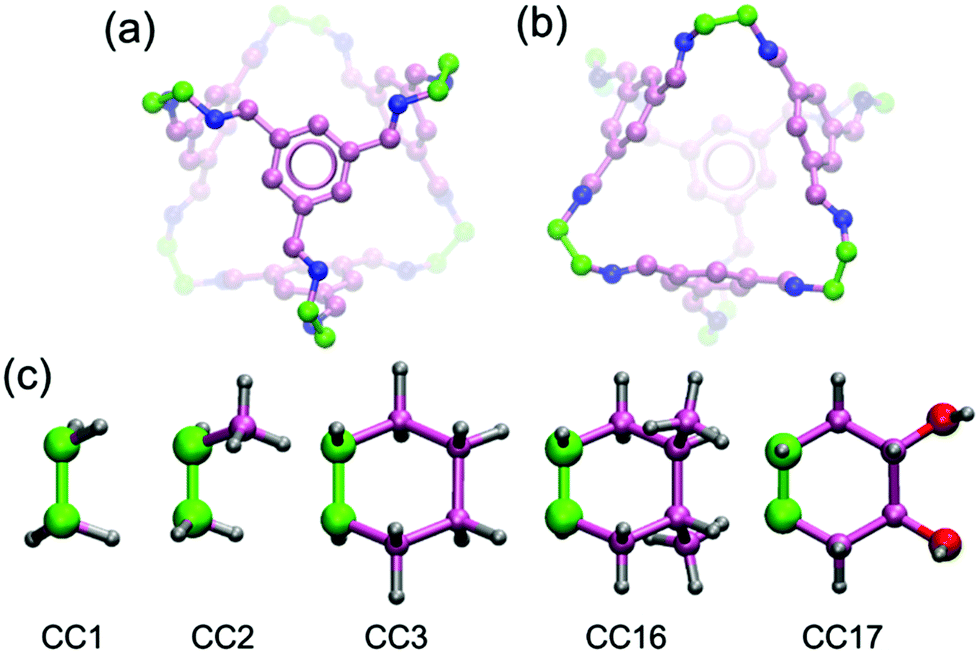
Based on the above discussed salient features (e.g. easy fabrication into membranes and water stability), we envision that POCs might be intriguing membrane materials for liquid phase separations. In this work, we report the first proof-of-concept simulation study to examine crystalline POCs as RO membranes for water desalination. Five POCs are examined namely CC1, CC2, CC3, CC16 and CC17.17,18 Synthesized by the condensation reactions of 1,3,5-triformylbenzene with various aliphatic diamines, the five POCs share a similar [4 + 6] tetrahedral cage (Fig. 1a and b). The cage contains four approximately triangular windows and six peripheries. By varying the periphery groups (Fig. 1c), different crystal structures are formed. Following this introduction, the models of the POC membranes, as well as the simulation methods used, are briefly described in Section 2. In Section 3, water flow and salt rejection through the POC membranes are presented and compared with other membranes, and the effects of pore morphology are examined; moreover, water dynamics and structure in POCs are discussed. Finally, the concluding remarks are summarized in Section 4.
 |
| | Fig. 1 (a) and (b) Top and bottom views of tetrahedral cage. Green carbon atoms are the linkages between two arene planes. Hydrogen atoms are not shown for clarity. (c) Periphery groups of CC1, CC2, CC3, CC16 and CC17. Color code: C (pink), N (blue), O (red) and H (gray). | |
2. Models and methods
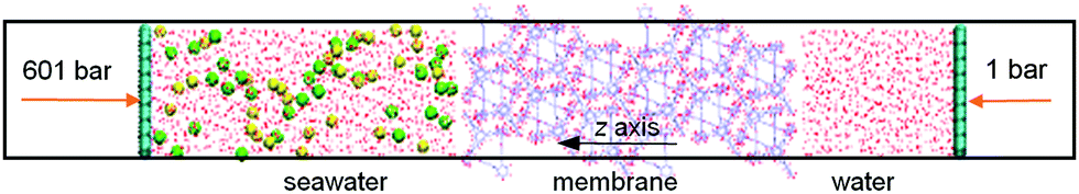
Water desalination through a POC membrane was simulated in a system shown in Fig. 2. A feed chamber with seawater was separated from a permeate chamber with pure water by the POC membrane. Seawater was mimicked by an aqueous NaCl solution with a concentration of 0.6 M. Along the z direction, the lengths of the feed and permeate chambers were 8.0 and 4.0 nm, respectively. The large size of the feed chamber was to ensure that seawater concentration would not alter appreciably during the simulation. Two graphene plates existed in the two chambers and they could self-adjust their positions during simulation under hydraulic pressures Pfeed and Ppermeate, respectively. The periodic boundary conditions were exerted in x, y and z axes; thus the membrane could be considered as infinitely large. To diminish the effects of periodic images along the z axis, a vacuum of 3 nm was added on each side of the system.
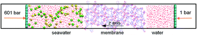 |
| | Fig. 2 A simulation system for water desalination. | |
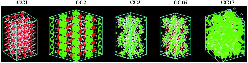
The five POC membranes (CC1, CC2, CC3, CC16, CC17) were constructed from their crystal structures based on experimentally crystallographic data.17,18 Specifically, CC1, CC3, CC16 and CC17 were the R-conformers, while CC2 was the S-conformer. For CC1, the unit cell was replicated by 3 × 6 in the a and b directions, and the b direction was aligned to the z axis of the simulation system. For CC2, the unit cell was replicated by 2 × 2 × 5 in the a, b and c directions, and the c direction was aligned to the z axis. For CC3 and CC16, the original crystals were cleared on the (111) plane, which is their naturally exposed surface,19 and rotated thus the (111) plane was normal to the z axis. For CC17, the unit cell was duplicated in the a and b directions, while the c direction was aligned to the z axis. The pore morphologies of the POCs were analyzed using the Zeo++ package20 with a probe diameter of 2.65 Å, which is the kinetic diameter of water.21Fig. 3 shows the interconnected and disconnected pores in the POCs. The pores are disconnected in CC1, partially interconnected in CC2, and largely interconnected in the other three POCs (particularly CC17). As we shall see below, this feature largely governs water permeation in a RO process.
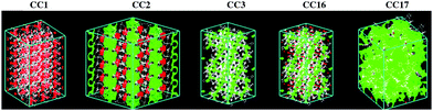 |
| | Fig. 3 Pore morphologies. Green: interconnected and red: disconnected. White: membrane. | |
The POCs were described by the Optimized Potentials for Liquid Simulations all atom (OPLS-AA) force field,22 which was demonstrated to be reliable to reproduce the structure and energetics of POCs.23 To incorporate the flexibility of POCs, the bonded potential consisted of stretching, bending and torsional terms
| |  | (1) |
| |  | (2) |
| | 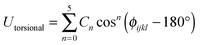 | (3) |
where
kr,
kθ and
Cn are the force constants;
rij,
θijk,
ϕijkl are bond lengths, angles, and proper dihedrals, respectively; and
r0ij and
θ0ijk are the equilibrium values. In addition, the nonbonded potential included the Lennard-Jones (LJ) and Coulombic terms
| | 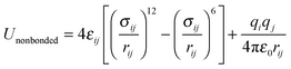 | (4) |
where
εij and
σij are the well depth and the collision diameter,
rij is the distance between the atoms
i and
j,
qi is the atomic charge of atom
i, and
ε0 = 8.8542 × 10
−12 C
2 N
−1 m
−2 is the permittivity of vacuum. The atomic charges of POCs were calculated using density functional theory (DFT) based on individual molecular cages. The DFT calculations used the Becke exchange plus Lee–Yang–Parr functional (B3LYP) and 6-311++g(d,p) basis sets, and were conducted using GAUSSIAN 09.
24 By fitting the electrostatic potentials from DFT calculations, the atomic charges were estimated. Tables S1–S4 (ESI
†) list all the potential parameters in
eqn (1)–(4) for the POCs. Na
+ and Cl
− ions were described as charged LJ particles with parameters from the OPLS-AA; water was mimicked by the 3 point-transferable intermolecular potential (TIP3P).
25 The carbon atoms in graphene plates were modeled with parameters as used for carbon nanotubes.
26
For each system, energy minimization was initially performed using the steepest descent method, then velocities were assigned according to the Maxwell–Boltzmann distribution at 300 K, Finally, molecular dynamics (MD) simulation was conducted at 300 K with pfeed = 601 bar and ppermeate = 1 bar. Throughout the simulation, the system size was kept constant. The temperature was controlled using the Nosé–Hoover thermostat with a relaxation time of 0.2 ps. We should note that the pfeed applied is substantially higher than practical values. This is a common practice in non-equilibrium MD simulations, e.g., extremely high pressures (up to 600 MPa) were set to simulate water desalination through graphene and carbon nanotubes.27,28 The reason is that a very small time step (femtosecond) is used in most MD simulations, and the current computational resources allow most simulations to be conducted for tens – hundreds of nanoseconds. Such a time scale is much shorter compared with practical processes. Therefore, high pressure is commonly used in MD simulations to accelerate the process while still capturing the underlying physics. To incorporate membrane flexibility, the atoms in the POC membrane were allowed to fluctuate; nevertheless, the heavy atoms were restrained in the z axis by a force constant of 1 kJ (mol nm2)−1. Furthermore, the force constant was varied to 10, 100 and 1000 kJ (mol nm2)−1 to examine its quantitative effect. The carbon atoms of graphene plates were restrained in the x and y axes with a force constant of 1000 kJ (mol nm2)−1, while they were movable along the z axis. A cutoff of 12 Å was used to calculate both LJ interactions and electrostatic interactions, and the particle-mesh Ewald method was used to evaluate the long-range electrostatic interactions with a grid spacing of 1.2 Å. A time step of 2 fs was used for integration and the trajectory was saved every 2 ps. The MD simulation duration was 50 ns and conducted using GROMACS v.5.0.6.29
3. Results and discussion
Water flow and salt rejection
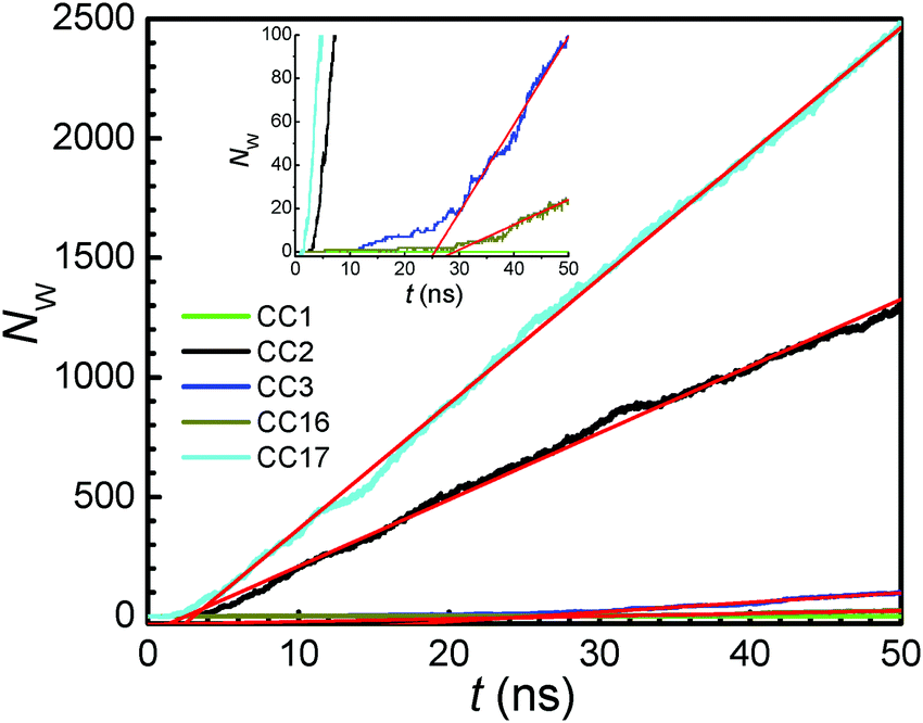
Under a pressure gradient Δp = pfeed − ppermeate, water flows from the feed to the permeate chamber leading to a RO process. Fig. 4 shows the net water flow Nwversus time t through the POC membranes at Δp = 600 bar. Despite chemically similar structure, the five POC membranes exhibit different magnitudes of Nw. For the CC17 membrane, the Nw increases linearly after a short time lag tlag of about 1 ns. The occurrence of time lag is because the membrane is initially dry, thus water needs to fill in the membrane before entering the permeate chamber. A similar trend is observed for the CC2 membrane with a longer tlag of 3 ns. In Fig. S2 and S3 (ESI†), the density profiles of water, as well as ions, at different times are plotted for CC2 and CC17. Initially, no water exists in the membrane interior. Along with time, water moves progressively into and passes through the membrane. Water density in CC17 is higher than in CC2 due to a porous network in CC17. Comparatively, CC3 and CC16 membranes have tlag of 12 and 28 ns, respectively, and their Nw are substantially lower than CC17 and CC2 membranes. For CC1, there is essentially no Nw within 50 ns simulation duration. Apparently, the CC1 membrane is impermeable to water, thus not applicable to water desalination.
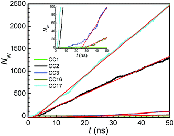 |
| | Fig. 4 Net water flow versus time. The red lines are linear fits to the curves. | |
As mentioned earlier, the membrane atoms were allowed to fluctuate but with heavy atoms restrained in the z axis by a force constant of 1 kJ (mol nm2)−1. To closely examine the effect of membrane flexibility, the force constant was varied to 10, 100 and 1000 kJ (mol nm2)−1 for the CC3 membrane. In Fig. S4 (ESI†), it is clearly seen that the pore radius and water flow are not discernibly affected by the force constant, suggesting the weak effect of membrane flexibility. This is in remarkable contrast with the diffusion of gas molecules (e.g. CO2 and N2) in POCs,17,30 because water has a smaller kinetic diameter (2.65 Å versus 3.30 Å for CO2 and 3.64 Å for N2)21 and hence less restricted by the membrane.
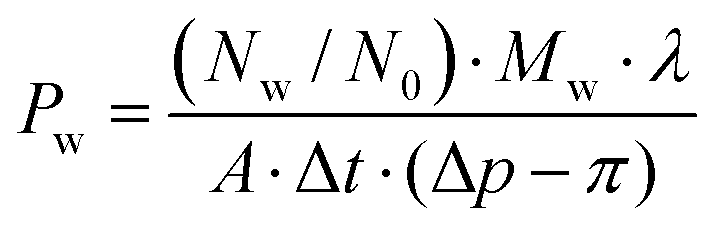
From the linear relationship between Nw and t, water permeability Pw can be estimated by
| | 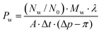 | (5) |
where
N0 is the Avogadro constant (6.022 × 10
23),
Mw is the molecular weight of water (18.015 g mol
−1),
λ is the membrane thickness,
A is the membrane cross-section area, Δ
t is the time duration, Δ
p is the pressure gradient (600 bar), and
π is the osmotic pressure of 0.6 M NaCl solution (about 30 bar). For a membrane, its permeability is an intrinsic property, and in principle, independent of the membrane area and thickness. Fig. S5 (ESI
†) illustrates the effect of system size on water flow through the CC17 membrane. Upon increasing the membrane area four times (from 2 × 2 × 1 to 4 × 4 × 1), the
Nw also increases four times. On the other hand, the
Nw is reduced by half when the membrane thickness doubles (from 2 × 2 × 1 to 2 × 2 × 2); meanwhile, the
tlag becomes longer as more time is required for water to enter and pass through a thicker membrane. Nevertheless, the
Pw is very close in all the three cases (Table S5, ESI
†), indicating that the system used is reliable without a discernible size effect.
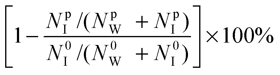
In addition to water permeability, salt rejection is another crucial metric to evaluate the performance of a membrane for water desalination. Here, salt rejection was calculated from
| | 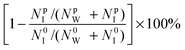 | (6) |
where
NpW and
NpI are the numbers of permeated water molecules and ions, respectively, while
N0w and
N0I are the numbers in the feed chamber before the RO process. Based on the two metrics (permeability and salt rejection), the performance of four POC (CC2, CC3, CC16 and CC17) membranes is plotted in
Fig. 5 and compared with other membranes. The
Pw in CC17 is 3.12 × 10
−6 kg m (m
2 h bar)
−1 and higher than in other POC membranes, whereas salt rejection in CC17 is only 89%. As demonstrated in Fig. S3 (ESI
†), a few ions are observed to pass through CC17. Although CC2, CC3 and CC16 have excellent salt rejection of 100%, CC16 and CC3 possess much lower
Pw (1.09 × 10
−7 and 4.72 × 10
−7) compared with CC2 (2.05 × 10
−6). Overall, CC2 appears to be the best POC membrane for water desalination. The
Pw in CC2 is higher than in several 2D membranes such as graphene,
27 graphyne
31 and CTF-1,
32 and one order of magnitude higher than in a polyamide membrane,
33 commercial seawater RO, brackish RO and high-flux RO membranes.
34 It is also higher than the
Pw in ZIFs from our recent simulation studies.
35–37 This demonstrates that CC2 might be an intriguing candidate for water desalination with high
Pw and complete salt rejection. It is worthwhile to note that in a membrane separation process, the concentration gradient exists at the membrane/solution interface, which would cause concentration polarization and affect separation performance. From a microscopic point of view, this effect has been incorporated in our simulations because all the interactions (including ion–ion, ion–water, ion–membrane, water–water, water–membrane) were calculated on the basis of their actual positions at every time step, which subsequently determined the transport of water and ions.
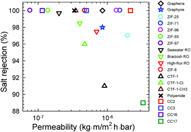 |
| | Fig. 5 Performance of POCs and other membranes (graphene,27 graphyne,31 CTFs,32 polyamide,33 commercial RO34 and ZIFs35–37). | |
Effects of pore morphology
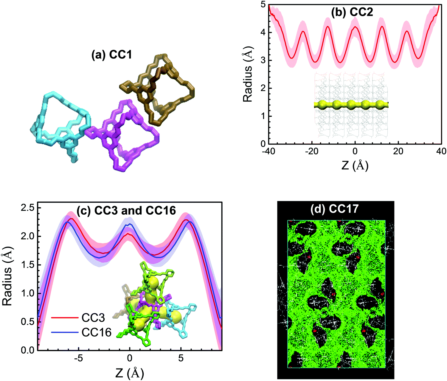
As mentioned above, the five POC membranes differ in pore morphology and exhibit different performance, particularly in water flow. Therefore, it is important to understand the effects of pore morphology. In CC1, the pores are disconnected (Fig. 3a) because the cages in CC1 are packed with an arene-to-window mode as illustrated in Fig. 6a, which blocks the pathway between neighboring cages; consequently, there is no water flow through CC1. The assembly of CC2 is analogous to CC1, but its periphery methyl groups disrupt packing, thus leading to straight pores along the z-axis (Fig. 3 and 6b). The pore radius profile and morphology were estimated using the HOLE program38 by averaging over 1000 snapshots from the last 10 ns of simulation. Fluctuations are observed in the radius profile as the membrane is flexible. Although not shown here, the membrane thickness shifts slightly from original configuration (Fig. 2) as induced by water intrusion under a pressure gradient. Along the z-axis, the pore radius in CC2 ranges from 3 to 4 Å, which is preferential for high water flow and complete salt selectivity. In CC3 and CC16, an interconnected tetrahedral pore network is present due to window-to-window packing between neighbor cages (Fig. 6c, in which the z-axis is the distance to the middle of two cages). The pore radius varies from 1.6 and 2.3 Å, despite fluctuations, in CC3 and CC16. The tetrahedral pore network and the smaller pore radius in CC3 and CC16 underlie the lower water flow than in CC2. In CC17, the pore network is widely open at the membrane interface and most cages in the membrane are interconnected (Fig. 6d). Thus, CC17 is the most permeable to water among the five POC membranes under study. Furthermore, the pore opening in CC17 is around 10 Å and unable to block ion passage leading to unsatisfactory salt rejection.
 |
| | Fig. 6 (a) Cage packing in CC1. (b and c) Pore radius profiles in CC2, CC3 and CC16. The shaded regions indicate fluctuations and the insets denote pore morphologies. (d) Pore network in CC17. | |
Water dynamics and structure in POCs
It is interesting to examine how water permeates through the POC membranes. Fig. 7 shows the trajectories of randomly selected water molecules along the z-axis. The behavior differs in the four membranes. In CC2 and CC17, after permeating into the membrane from the feed chamber, most water molecules reside therein for a period of 2–9 ns, then leave the membrane and enter into the permeate chamber. Occasionally, a few water molecules move back to the membrane from the permeate chamber. This behavior is attributed to the relatively free water permeation through the straight large pores in CC2 and the porous network in CC17. Comparatively, water molecules stay in CC3 and CC16 for a much longer period (30–40 ns) because of their tetrahedral network and small radius, which are not favorable for water permeation.
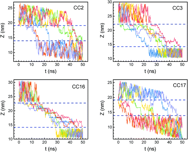 |
| | Fig. 7 Trajectories of randomly selected water molecules through POC membranes. Dashed lines indicate membrane interfaces. | |
Table 1 lists the permeation durations through the POC membranes averaged over all permeated water molecules after entering from the feed chamber and before leaving into the permeate chamber. Apparently, water resides in CC3 and CC16 longer than in CC2 and CC17 because the tetrahedral pore network in the former is not favorable for water permeation. Moreover, the membrane-thickness normalized specific permeation duration in CC3 is a bit shorter than in CC16, consistent with the slightly higher water permeability in CC3. Compared with CC2, the specific permeation duration in CC17 is longer despite higher permeability in CC17. The reasons are: (1) the straight pore in CC2 facilitates water permeation; (2) the hydroxyl groups present in CC17 exert stronger affinity for water and hence water is relatively less mobile than in CC2. On the other hand, the pore network at the CC17 membrane interface is wide open and water can readily enter into the membrane from the feed chamber; overall CC17 possesses the highest permeability.
Table 1 Water permeation and hydrogen bonds
| Membrane |
Membrane thickness (nm) |
Permeation duration (ns) |
Specific permeation duration (ns nm−1) |
Hydrogen bonds |
| CC1 |
5.32 |
∞ |
∞ |
0 |
| CC2 |
5.13 |
4.11 ± 1.23 |
0.80 ± 0.24 |
2.79 ± 0.06 |
| CC3 |
7.94 |
21.36 ± 4.68 |
2.69 ± 0.59 |
2.10 ± 0.06 |
| CC16 |
8.56 |
26.78 ± 4.51 |
3.13 ± 0.53 |
2.05 ± 0.04 |
| CC17 |
5.26 |
5.40 ± 1.82 |
1.03 ± 0.35 |
2.63 ± 0.02 |
The mean-squared displacements (MSDs) of water molecules along the z-axis in the membranes were estimated from
| | | MSDz(t) = 〈|zi(t0 + t) − zi(t0)|2〉i∈Ω | (7) |
where
zi is the
z-coordinate of atom
i,
Ω is a set of water molecules staying in the membrane from
t0 to
t0 +
t, and 〈⋯〉 denotes the ensemble average. As shown in
Fig. 8, water diffusion in the POC membranes is slower compared with the case in the bulk phase (at 298 K and 1 bar). In each membrane, the MSD tends to follow the Fickian mode after 100 ps, indicating that water molecules adopt normal diffusion; nevertheless, the MSD approaches a plateau at the end as the membrane is confined along the
z-axis. In the four membranes, the MSD decreases in the order of CC2 > CC17 > CC3 > CC16, despite a small difference between CC2 and CC17, as well as CC3 and CC16. This order is consistent with the increasing trend of the permeation duration in
Table 1. Again, we can see that water mobility in CC2 is higher than in CC17, despite the fact that the overall permeability is the highest in CC17.
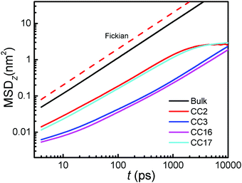 |
| | Fig. 8 MSDzversus time. | |
In addition to water dynamics, water structure in the membranes is examined by hydrogen bonds (HBs). To characterize a HB, two geometrical criteria were implemented: (1) the distance between a donor and an acceptor ≤0.35 nm and (2) the angle of hydrogen–donor–acceptor ≤30°.39 As listed in Table 1, there are on average 2.10 and 2.05 HBs per water molecule in CC3 and CC16, while 2.79 and 2.63 in CC2 and CC17, respectively. The relatively greater number of HBs in CC2 and CC17 is due to their larger pores and porous network. Moreover, the number of HBs in the membrane is reduced compared with that in the bulk phase (3.5). Such reduction of HBs is unfavorable for water entry from the bulk phase into the membrane, which however is overcome by the pressure gradient leading to RO. Comparing CC2 and CC17, we can see that the reduction of HBs is greater in CC17; however, water entry into CC17 is more readily than into CC2 leading to a higher permeability due to the widely open pore network at the membrane interface and periphery hydroxyl groups.
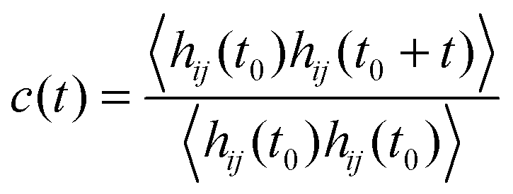
The relaxation of HBs for water molecules in the membranes is quantified by the autocorrelation function39,40
| |  | (8) |
where
h(
t) = 1 if two water molecules are hydrogen bonded at time
t and
h(
t) = 0 otherwise. Physically,
c(
t) signifies the probability for water molecules remaining hydrogen bonded at
t0 as well as
t +
t0. As shown in
Fig. 9,
c(
t) in all the POC membranes, as well as in the bulk phase, drop with time. At a given time, the
c(
t) in each membrane is greater than in the bulk phase. This is attributed to the confinement and interaction of the membrane, which restricts water motion in the membrane and leads to longer existence of HBs. The
c(
t) drop as CC16 > CC3 > CC17 > CC2, in accordance with the decreasing trend of permeation duration in
Table 1, and opposite to the increasing trend of MSD in
Fig. 8. Because of the presence of straight pores and porous network, water diffusion in CC2 and CC17 is faster than in CC3 and CC16; consequently, the
c(
t) in the former is lower, thus leading to faster relaxation of HBs. Based on
c(
τHB) =
e−1,
41 the lifetimes
τHB are estimated to be 3.0, 3.3, 3.5 and 3.6 ps for CC2, CC17, CC3 and CC16, respectively. Compared with the bulk phase (1.4 ps), the
τHB in the membranes are 1–2 times longer; nevertheless, they are close to that in ZIF-8 (3.5 ps), implying a similar confinement environment.
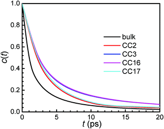 |
| | Fig. 9 Autocorrelation functions of HBs. | |
4. Conclusions
Five POC membranes (CC1, CC2, CC3, CC16 and CC17) have been examined for water desalination. Despite a similar chemical structure, their pore morphologies and desalination capabilities vary considerably. In the absence of interconnected pores, CC1 is impermeable to water and not suitable for desalination. Consisting of straight pores with a radius of 3 to 4 Å, CC2 exhibits high water permeability and complete salt rejection. CC17 also has high water permeability, due to its widely open pore network, but salt rejection is compromised to 89%. With an interconnected tetrahedral pore network, both CC3 and CC16 possess intermediate water permeability. Overall, CC2 is identified to be the best among the five POC membranes for water desalination and outperforms other membranes (e.g. graphene, polyamide, and commercial RO).
This simulation study demonstrates that POCs are intriguing materials for water desalination, and it would provoke further interest in this area. However, we should note several limitations in our simulations: (1) the POC membranes were assumed to be stable in the simulation systems. Although POCs have been experimentally found to remain stable in water for a certain period, their long-term stability needs to be further tested. There is ongoing endeavor aiming to improve the stability of POCs. Alternatively, POCs can be utilized as fillers in polymer membranes to fabricate mixed-matrix membranes. This approach may potentially produce stable and robust membranes of practical relevance. (2) Due to computational power, the POC membranes were very thin and cannot be straightforwardly compared with real membranes. (3) Also due to computational power, the pressure gradient applied was significantly higher than practical RO processes. Therefore, more simulation endeavors are desirable by incorporating more practical situations and conditions. Despite these limitations, the bottom-up insights are provided from this simulation study for water permeation through the POC membranes, which might facilitate the development of new POCs and other porous materials for high-performance water desalination.
Acknowledgements
We gratefully acknowledge the A*STAR (R-279-000-475-305 and R-279-000-431-305) for financial support.
References
- M. A. Shannon, P. W. Bohn, M. Elimelech, J. G. Georgiadis, B. J. Marinas and A. M. Mayes, Nature, 2008, 452, 301 CrossRef CAS PubMed.
- T. Mezher, H. Fath, Z. Abbas and A. Khaled, Desalination, 2011, 266, 263 CrossRef CAS.
- M. M. Pendergast and E. M. Hoek, Energy Environ. Sci., 2011, 4, 1946 CAS.
- K. P. Lee, T. C. Arnot and D. Mattia, J. Membr. Sci., 2011, 370, 1 CrossRef CAS.
- M. C. Duke, J. O’Brien-Abraham, N. Milne, B. Zhu, J. Y. S. Lin and J. C. Diniz da Costa, Sep. Purif. Technol., 2009, 68, 343 CrossRef CAS.
- B. Zhu, Z. Hong, N. Milne, C. M. Doherty, L. Zou, Y. S. Lin, A. J. Hill, X. Gu and M. Duke, J. Membr. Sci., 2014, 453, 126 CrossRef CAS.
- J. K. Holt, H. G. Park, Y. Wang, M. Stadermann, A. B. Artyukhin, C. P. Grigoropoulos, A. Noy and O. Bakajin, Science, 2006, 312, 1034 CrossRef CAS PubMed.
- R. R. Nair, H. A. Wu, P. N. Jayaram, I. V. Grigorieva and A. K. Geim, Science, 2012, 335, 442 CrossRef CAS PubMed.
- S. P. Surwade, S. N. Smirnov, I. V. Vlassiouk, R. R. Unocic, G. M. Veith, S. Dai and S. M. Mahurin, Nat. Nanotechnol., 2015, 10, 459 CrossRef CAS PubMed.
- H. Wang, T.-S. Chung, Y. W. Tong, K. Jeyaseelan, A. Armugam, Z. Chen, M. Hong and W. Meier, Small, 2012, 8, 1185 CrossRef CAS PubMed.
- M. Wang, Z. Wang, X. Wang, S. Wang, W. Ding and C. Gao, Environ. Sci. Technol., 2015, 49, 3761 CrossRef CAS PubMed.
- T. Hasell and A. I. Cooper, Nat. Rev. Mater., 2016, 1, 16053 CrossRef CAS.
- A. F. Bushell, P. M. Budd, M. P. Attfield, J. T. Jones, T. Hasell, A. I. Cooper, P. Bernardo, F. Bazzarelli, G. Clarizia and J. C. Jansen, Angew. Chem., Int. Ed., 2013, 52, 1253 CrossRef CAS PubMed.
- Q. Song, S. Jiang, T. Hasell, M. Liu, S. Sun, A. K. Cheetham, E. Sivaniah and A. I. Cooper, Adv. Mater., 2016, 28, 2629 CrossRef CAS PubMed.
- T. Hasell, M. Schmidtmann, C. A. Stone, M. W. Smith and A. I. Cooper, Chem. Commun., 2012, 48, 4689 RSC.
- M. Liu, M. A. Little, K. E. Jelfs, J. T. Jones, M. Schmidtmann, S. Y. Chong, T. Hasell and A. I. Cooper, J. Am. Chem. Soc., 2014, 136, 7583 CrossRef CAS PubMed.
- T. Tozawa, J. T. Jones, S. I. Swamy, S. Jiang, D. J. Adams, S. Shakespeare, R. Clowes, D. Bradshaw, T. Hasell, S. Y. Chong, C. Tang, S. Thompsn, J. Parker, A. Trewin, J. Basca, A. M. Slawin, A. Steiner and A. I. Cooper, Nat. Mater., 2009, 8, 973 CrossRef CAS PubMed.
- P. S. Reiss, M. A. Little, V. Santolini, S. Y. Chong, T. Hasell, K. E. Jelfs, M. E. Briggs and A. I. Cooper, Chem. – Eur. J., 2016, 22, 16547 CrossRef CAS PubMed.
- M. J. Bojdys, T. Hasell, N. Severin, K. E. Jelfs, J. P. Rabe and A. I. Cooper, Chem. Commun., 2012, 48, 11948 RSC.
- T. F. Willems, C. H. Rycroft, M. Kazi, J. C. Meza and M. Haranczyk, Microporous Mesoporous Mater., 2012, 149, 134 CrossRef CAS.
-
A. F. Ismail, C. Khulbe and T. Matsuura, Gas Separation Membranes, Springer, 2015 Search PubMed.
- W. L. Jorgensen, D. S. Maxwell and J. Tirado-Rives, J. Am. Chem. Soc., 1996, 118, 11225 CrossRef CAS.
- N. Giri, M. G. Del Pópolo, G. Melaugh, R. L. Greenaway, K. Rätzke, T. Koschine, L. Pison, M. F. C. Gomes, A. I. Cooper and S. L. James, Nature, 2015, 527, 216 CrossRef CAS PubMed.
-
M. J. Frisch, G. W. Trucks, H. B. Schlegel, G. E. Scuseria, M. A. Robb, J. R. Cheeseman, V. G. Zakrzewski, J. A. Montgomery, R. E. Stratmann, J. C. Burant, S. Dapprich, J. M. Millam, A. D. Daniels, K. N. Kudin, M. C. Strain, O. Farkas, J. Tomasi, V. Barone, M. Cossi, R. Cammi, B. Mennucci, C. Pomelli, C. Adamo, S. Clifford, J. Ochterski, G. A. Petersson, P. Y. Ayala, Q. Cui, K. Morokuma, D. K. Malick, A. D. Rabuck, K. Raghavachari, J. B. Foresman, J. Cioslowski, J. V. Ortiz, B. B. Stefanov, G. Liu, A. Liashenko, P. Piskorz, I. Komaromi, R. Gomperts, R. L. Martin, D. J. Fox, T. Keith, M. A. Al-Laham, C. Y. Peng, A. Nanayakkara, C. Gonzalez, M. Challacombe, P. M. W. Gill, B. G. Johnson, W. Chen, M. W. Wong, J. L. Andres, M. Head-Gordon, E. S. Replogle and J. A. Pople, Gaussian 09, Revision D.01, Gaussian, Inc., Wallingford CT, 2009 Search PubMed.
- W. L. Jorgensen, J. Chandrasekhar, J. D. Madura, R. W. Impey and M. L. Klein, J. Chem. Phys., 1983, 79, 926 CrossRef CAS.
- G. Hummer, J. C. Rasaiah and J. P. Noworyta, Nature, 2001, 414, 188 CrossRef CAS PubMed.
- D. Cohen-Tanugi and J. C. Grossman, Nano Lett., 2012, 12, 3602 CrossRef CAS PubMed.
- Q. Chen and X. Yang, J. Membr. Sci., 2015, 496, 108 CrossRef CAS.
- D. Van Der Spoel, E. Lindahl, B. Hess, G. Groenhof, A. E. Mark and H. J. C. Berendsen, J. Comput. Chem., 2005, 26, 1701 CrossRef CAS PubMed.
- D. Holden, K. E. Jelfs, A. I. Cooper, A. Trewin and D. J. Willock, J. Phys. Chem. C, 2012, 116, 16639 CAS.
- J. Kou, X. Zhou, H. Lu, F. Wu and J. Fan, Nanoscale, 2014, 6, 1865 RSC.
- L.-C. Lin, J. Choi and J. C. Grossman, Chem. Commun., 2015, 51, 14921 RSC.
- W. Gao, F. She, J. Zhang, L. F. Dumee, L. He, P. D. Hodgson and L. Kong, J. Membr. Sci., 2015, 487, 32 CrossRef CAS.
- M. T. M. Pendergast and E. M. V. Hock, Energy Environ. Sci., 2011, 4, 1946 CAS.
- Z. Q. Hu, Y. F. Chen and J. W. Jiang, J. Chem. Phys., 2011, 134, 134705 CrossRef PubMed.
- K. M. Gupta, K. Zhang and J. W. Jiang, Langmuir, 2015, 31, 13230 CrossRef CAS PubMed.
- K. M. Gupta, Z. W. Qiao, K. Zhang and J. W. Jiang, ACS Appl. Mater. Interfaces, 2016, 8, 13392–13399 CAS.
- O. S. Smart, J. M. Goodfellow and B. A. Wallace, Biophys. J., 1993, 65, 2455 CrossRef CAS PubMed.
- A. Luzar and D. Chandler, Nature, 1996, 379, 55 CrossRef CAS.
- D. C. Rapaport, Mol. Phys., 1983, 50, 1151 CrossRef CAS.
- H. F. Xu and B. J. Berne, J. Phys. Chem. B, 2001, 105, 11929 CrossRef CAS.
Footnote |
| † Electronic supplementary information (ESI) available: Atomic types, non-bonded and bonded potential parameters in POCs, density profiles of water and ions, the effect of membrane flexibility on the pore radius and water flow, and the effect of system size on water flow. See DOI: 10.1039/c7cp02670f |
|
| This journal is © the Owner Societies 2017 |
Click here to see how this site uses Cookies. View our privacy policy here. 
 Open Access Article
 This Open Access Article is licensed under a
  and
Jianwen
Jiang
and
Jianwen
Jiang