 Open Access Article
Creative Commons Attribution 3.0 Unported Licence
Chiral segregation driven by a dynamical response of the adsorption footprint to the local adsorption environment: bitartrate on Cu(110)†
G. R.
Darling
*,
M.
Forster
,
C.
Lin
,
N.
Liu
,
R.
Raval
* and
A.
Hodgson
*
Surface Science Research Centre and Department of Chemistry, University of Liverpool, Liverpool L69 3BX, UK. E-mail: darling@liverpool.ac.uk; raval@liverpool.ac.uk; ahodgson@liverpool.ac.uk
First published on 22nd February 2017
Abstract
Local or global ordering of chiral molecules at a surface is a key step in both chiral separation and heterogeneous enantioselective catalysis. Using density functional theory and scanning probe microscopy results, we find that the accepted structural model for the well known bitartrate on Cu(110) chiral system cannot account for the chiral segregation observed. Instead, we show that this strongly bound, chiral adsorbate changes its adsorption footprint in response to the local environment. The flexible adsorption geometry allows bitartrate to form stable homochiral trimer chains in which the central molecule restructures from a rectangular to an oblique footprint, breaking its internal hydrogen bonds in order to form strong intermolecular hydrogen bonds to neighbouring adsorbates. Racemic structures containing mixed enantiomers do not form strong hydrogen bonds, providing the thermodynamic driving force for the chiral separation that is observed experimentally. This result shows the importance of considering the dynamical response of molecular adsorption footprints at the surface in directing chiral assembly and segregation. The ability of strongly-chemisorbed enantiomers to change footprint depending on the local adsorption environment indicates that supramolecular assemblies at surfaces may exhibit more complex dynamical behaviour than hitherto suspected, which, ultimately, could be tailored to lead to environment and stimuli-responsive chiral surfaces.
1. Introduction
The nanoscale control of chiral molecular assembly at surfaces is of central importance in fields as diverse as chiral separations,1,2 heterogeneous enantioselective catalysis,3,4 plasmonics,5 chiroptical switching6,7 and biosensors.8 In all cases, the surface function is profoundly influenced by how individual enantiomers organize at the local and the global level, therefore the outstanding problem in the field is to understand the factors that drive enantiomer assembly and segregation. The importance of intermolecular interactions, such as hydrogen-bonding, steric repulsions and van der Waals interactions, in controlling chiral assembly in 2- and 3-D has been well established.1,9–15 Recent work has shown that the adsorption footprints adopted by individual molecules also play a critical role in determining the local and global organization of the adsorbed molecules.16,17 For example, in racemic systems that contain an equal population of right- and left-handed molecules, adsorption footprints are key in determining whether the system organizes into an ordered heterochiral array, spontaneously segregates to form distinct homochiral domains, or assembles as a solid solution with a random arrangement of enantiomers,18,19 with each arrangement expected to elicit very different physical, chemical and biological responses.The assembly of enantiopure bitartrate on Cu(110) represents the first global homochiral surface reported in the literature and has become a model system, serving as a benchmark for understanding chiral phenomena in 2D systems.20–29 Here, we show that the widely-accepted model for this structure,20–24 based on a rectangular adsorption footprint for bitartrate, is unable to explain either the chiral segregation that is observed for racemic adsorption, or the contrast observed in scanning tunnelling microscopy (STM) images. Using dispersion corrected density functional theory (DFT) we show that the global ordering and chiral segregation arises from the ability of bitartrate to change its adsorption footprint in response to the local environment. Bitartrate forms trimers in which the central bitartrate molecule over-rides the adsorption preference of an individual molecule and locally re-structures to adopt an oblique footprint. In doing so, this bitartrate breaks its internal hydrogen bonds and instead forms hydrogen bonds to the carboxylate groups of the two neighbouring bitartrate units. This local dynamical response by 1/3 of the molecules in the trimer leads to the formation of strong inter-molecular hydrogen bonds that stabilise the homochiral structure, providing the driving force for chiral segregation.
The molecular adsorption footprint is of central importance in dictating the supramolecular assembly of molecules at surfaces and the orientation of their functional groups, which in turn dictate the response of the interface to the environment, to guest molecules and the alignment of reactants in ‘modifier-directed’ heterogeneous enantioselective catalysis.4,30,31 The ‘chiral footprint model’ is also implicated in the origin of optical activity in metal-based electronic transitions.7,32 Our work shows the importance of considering the dynamical response of the molecular adsorption footprint to the local adsorption environment, leading to more nuanced behaviour than hitherto anticipated, which could, ultimately, be tailored to create environment and stimuli-responsive chiral surfaces.
2. Methods
STM images were recorded in an ultra high vacuum STM (Specs 150 Aarhus at 100 K or Createc STM/AFM at 77 K) operated in constant current mode with an electrochemically etched tungsten tip. Images were acquired in constant current mode, with bias voltages quoted relative to the sample, so that positive voltages correspond to electrons tunnelling into the surface (empty state images). The copper surface was prepared by argon ion sputtering at 500 eV, followed by annealing to 800 K, yielding an average terrace size of approx. 800 Å. Further details have been given previously.33 Tartaric acid (99%) was obtained from Sigma Aldrich and used without further purification. The adsorbate was deposited from a small resistively heated glass tube, separated from the main vacuum chamber by a gate valve and differentially pumped by a turbomolecular pump.20,34 The sample was thoroughly outgassed at ca. 340 K and then heated to ca. 370 K to sublime on to the copper crystal. During sublimation the chamber pressure was typically <2 × 10⁻⁹ mbar. Following deposition the sample was heated to 350 K to order the bitartrate phase.Total energy calculations were carried out for trial structures using VASP35,36 with the optB86b-vdW exchange–correlation functional,37,38 which includes dispersion interactions. We note that previous calculations examined bitartrate adsorption and lateral interactions in smaller unit cells,22,23 and total energy calculations including dispersion forces have not been reported for the correct chiral unit cell. Single molecule adsorption was modelled with a (5 × 4) supercell in a 5 layer slab, with the bottom two layers fixed, using a 7 × 6 × 1 k-point mesh, while the (1 2, −9 0) (R,R) unit cell used a 12 × 4 × 1 k-point set. Valence electron–core interactions were included using the projector augmented wave method,39,40 a plane wave cutoff energy of 400 eV and including dipole corrections perpendicular to the surface. All adsorption energies are quoted in eV per molecule, calculated relative to tartaric acid and hydrogen in the gas phase. STM images were calculated using the Tersoff–Hamann approximation in the implementation by Lorente and Persson.41,42
3. Results
3.1 STM of bitartrate on Cu(110)
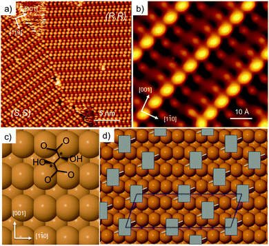
Adsorption of tartaric acid on Cu(110) has become a model system for exploring chiral assembly at surfaces. Tartaric acid has two chiral centres (designated either R or S), and two carboxylic acid groups that are directly involved in bonding to the surface. The system displays a number of different phases as the acid successively dehydrogenates to form the monotartrate and then bitartrate species.20,21,24,43–46 The doubly dehydrogenated bitartrate phase, formed by adsorbing tartaric acid above 350 K, undergoes classic Pasteur resolution, with a racemic mixture of (R,R) and (S,S) tartaric acid spontaneously segregating into separate mirror domains of the pure enantiomers to form locally organised homochiral domains,20,21Fig. 1. Enantiopure adsorption leads to a globally organised homochiral assembly, where a single-handed organisation is sustained from the nano- to the macro-scale. | ||
| Fig. 1 STM images showing (a) domains of (9 0, −1 2) (S,S) and (1 2, −9 0) (R,R) bitartrate formed by dosing a racemic mixture of tartaric acid (300 K, −880 meV, 500 pA) and (b) a high resolution image of the (R,R) structure formed by dosing a single enantiomer (77 K, −510 meV, 280 pA). Schematics showing (c) the (R,R) bitartrate molecule (chiral centres marked *) and (d) the arrangement of (R,R) bitartrate in the (9 0, −1 2) unit cell proposed previously.22 | ||
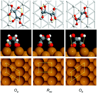
Fig. 1a shows the STM image of racemic tartaric acid adsorbed on Cu(110), forming segregated domains of (R,R) (1 2, −9 0) and (S,S) (9 0, −1 2) structure, respectively. Fig. 1b shows an STM image for the R,R bitartrate structure in greater detail. The bitartrate adopts a unique single-handed chiral organisation, containing extended chiral chains running along the [1 −1 4] direction, assembled from trimers aligned in a staggered arrangement across the close packed Cu rows. A well-defined gap is found between the bitartrate chains. The STM images are rather insensitive to the bias voltage, although the contrast of the channel is sensitive to the tip state (see ESI† for more detail). Current models of the bitartrate phase22–24 are based on bitartrate bonding to the surface via both carboxylate groups, bridging across adjacent close packed Cu rows to create a rectangular (Rec) footprint, as shown in Fig. 1c. Although it was originally suggested that the bitartrate trimers were linked by hydrogen bonds,20 subsequent DFT calculations concluded that the bitartrate molecules retain their intra-molecular hydrogen bonds and do not participate in direct inter-molecular interactions, with the chiral arrangement attributed to an improved packing energy for homochiral (R,R) bitartrate in the structure shown in Fig. 1d.22 However, the STM data for these homochiral domains, Fig. 1b, show that the central feature of each bitartrate trimer images considerably brighter than the outer units. Under some tip conditions the central feature of the bitartrate structure splits, (probably caused by bitartrate or another adsorbate on the tip, see ESI†), again, imaging quite differently from the outer units. The inequivalence of the central feature in STM is surprising; if the structure is built from three non-interacting bitartrate units, each adsorbed with a rectangular footprint and equivalent at the local level,22 it is not clear why the central feature should image so differently from its neighbours.
3.2 Theoretical modelling
To understand the structure of bitartrate on Cu(110) we carried out total energy calculations using VASP35,36 with the optB86b-vdW exchange–correlation functional,37,38 which includes dispersion interactions. We note that previous calculations examined bitartrate adsorption and lateral interactions in smaller unit cells,22,23 without including dispersion forces, and total energy calculations have not been reported for the correct chiral unit cell.| Isomers | Footprint | E ad (eV) | ΔEad (eV) | |
|---|---|---|---|---|
| I | (R,R):(R,R):(R,R) | R ec R ec R ec | −2.152 | +0.123 |
| II | (R,R):(R,R):(R,R) | R ec O a R ec | −2.275 | 0.0 |
| III | (R,R):(R,R):(R,R) | O a R ec O a | −2.244 | +0.031 |
| IV | (R,R):(R,R):(R,R) | O a O a O a | −2.079 | +0.196 |
| V | (S,S):(S,S):(S,S) | R ec R ec R ec | −2.163 | +0.112 |
| VI | (S,S):(S,S):(S,S) | R ec O a R ec | −2.115 | +0.160 |
| VII | (S,S):(S,S):(S,S) | O a R ec O a | −2.081 | +0.194 |
| VIII | (R,R):(S,S):(R,R) | R ec R ec R ec | −2.161 | +0.114 |
| IX | (R,R):(S,S):(R,R) | O a O a O a | −2.157 | +0.118 |
| X | (S,S):(R,R):(S,S) | R ec O a R ec | −2.165 | +0.110 |
 | ||
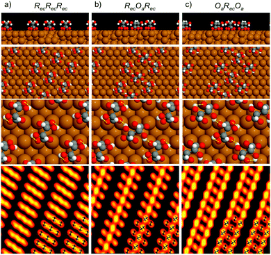
| Fig. 3 Calculated structures for (R,R) bitartrate trimers in the (1 2, −9 0) unit cell, arranged with (a) the RecRecRec configuration, (b) an RecOaRec arrangement and (c) an OaRecOa footprint. The top 2 rows show the end view of the chains and the overall arrangement of bitartrate trimers in the chains. The lower 2 rows show the inter- or intra-molecular hydrogen bonds within a trimer (marked as yellow lines) and, bottom row, simulated STM images for the different structures at the same bias voltage as Fig. 1b, (V = −500 meV). | ||
Since the DFT calculations show a clear preference for the bitartrate structure being assembled from RecOaRec trimer units, rather than the RecRecRec units previously supposed, we should consider if this structure is consistent with the STM images observed. The lower panels in Fig. 3 show a simulation of the STM images for the different structures. STM simulations of the RecRecRec structure (I) are characterised by a rather uniform intensity distributed across the trimer, with poor differentiation between the separate bitartrate molecules. In contrast, the RecOaRec and OaRecOa structures (II) and (III) both show well defined features associated with the individual bitartrate molecules and, importantly, a greater intensity on bitartrate molecules adsorbed with the Oa footprint rather than the Rec configuration. Such an intensity alternation is also observed in the experimental STM images, Fig. 1a and b, and is consistent with the minimum energy RecOaRec arrangement, structure (II), but not with either the RecRecRec or OaRecOa structures. In fact the RecOaRec arrangement, structure (II), was the only structure we found that reproduced the STM images observed in experiment acceptably, confirming that the bitartrate phase is built from hydrogen-bonded trimers arranged with an RecOaRec footprint.
 | ||
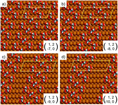
| Fig. 4 Unit cells simulated by DFT for the RecOaRec chain structure showing the width of the exposed Cu channel as the unit cell is progressively elongated from 7 to 10 Cu atoms along the 〈1−10〉 direction. The local geometry of bitartrate in the trimer chains remains the same as in Fig. 3b. | ||
4. Discussion and conclusions
Our results for bitartrate adsorption on Cu(110) indicate that bitartrate can adopt two different footprints on the surface, changing its molecular footprint from a rectangular to an oblique arrangement depending on its local adsorption environment. Bitartrate forms chains of trimers arranged in a staggered RecOaRec configuration, allowing the central Oa molecule to form strong hydrogen bonds to the neighbouring carboxylate groups and stabilising the homochiral phase. This result was unanticipated and changes our understanding of the driving forces that lead to chiral assembly and segregation in this system. The homochiral phase is more stable than mixed phases because it can form short strong H-bonds across the trimer, something that does not occur for mixed enantiomers. It is notable that, although bitartrate bonds to the surface via 4 strong O-metal bonds, the adsorption footprint is still able to respond dynamically to the presence of co-adsorbates to which it can form strong hydrogen bonds. Further work has shown that other polar species, such as water, can also cause bitartrate to restructure its adsorption footprint, implying that the chiral surface will be highly dynamic when other polar co-adsorbates are present. Such a dynamic local response has significant implications in systems where the bitartrate species acts as a chiral modifier during heterogeneous enantioselective catalysis,3,4 for example in hydrogenation over tartaric acid modified RANEY® nickel catalysts. Although these systems show no long range order, experiments find enantioselective reaction is accelerated by a direct hydrogen-bonding interaction between the bitartrate modifier and the substrate molecule,48 implying a local ordering of the reaction complex. The results obtained here imply that models for chiral segregation and ordering, and for selective chiral catalysis using modifiers such as bitartrate, must account properly for the dynamic response of the enantiomer and its adsorption footprint to the local environment, which may lead to complex and sensitive responses as reactant and reaction conditions are altered.Acknowledgements
This research was supported by UK EPSRC (EP/F00981X/1, EP/J019844/1, EP/K039687/1), EU 7th framework small scale collaborative project RESOLVE (NMP4-SL-2008-214340), EU Marie Curie Programs CHEXTAN (MRTN-CT-2004-512161) and Royal Society (IE131424). This work made use of the HECToR national high-performance computing service via our membership of the UK's HEC Materials Chemistry Consortium (EP/L000202 and EP/F067496).References
- L. Perez-Garcia and D. B. Amabilino, Chem. Soc. Rev., 2007, 36, 941–967 RSC.
- H. Xu, W. J. Saletra, P. Iavicoli, B. Van Averbeke, E. Ghijsens, K. S. Mali, A. Schenning, D. Beljonne, R. Lazzaroni, D. B. Amabilino and S. De Feyter, Angew. Chem., Int. Ed., 2012, 51, 11981–11985 CrossRef CAS PubMed.
- V. Demers-Carpentier, G. Goubert, F. Masini, R. Lafleur-Lambert, Y. Dong, S. Lavoie, G. Mahieu, J. Boukouvalas, H. L. Gao, A. M. H. Rasmussen, L. Ferrighi, Y. X. Pan, B. Hammer and P. H. McBreen, Science, 2011, 334, 776–780 CrossRef CAS PubMed.
- A. J. Gellman, W. T. Tysoe and F. Zaera, Catal. Lett., 2015, 145, 220–232 CrossRef CAS.
- V. K. Valev, J. J. Baumberg, C. Sibilia and T. Verbiest, Adv. Mater., 2013, 25, 2517–2534 CrossRef CAS PubMed.
- D. J. Dijken, J. M. Beierle, M. C. A. Stuart, W. Szymanski, W. R. Browne and B. L. Feringa, Angew. Chem., Int. Ed., 2014, 53, 5073–5077 Search PubMed.
- I. Dolamic, S. Knoppe, A. Dass and T. Burgi, Nat. Commun., 2012, 3, 798 CrossRef PubMed.
- Y. W. C. Cao, R. C. Jin and C. A. Mirkin, Science, 2002, 297, 1536–1540 CrossRef CAS PubMed.
- S. Katano, Y. Kim, H. Matsubara, T. Kitagawa and M. Kawai, J. Am. Chem. Soc., 2007, 129, 2511–2515 CrossRef CAS PubMed.
- P. Besenius, G. Portale, P. H. H. Bomans, H. M. Janssen, A. R. A. Palmans and E. W. Meijer, Proc. Natl. Acad. Sci. U. S. A., 2010, 107, 17888–17893 CrossRef CAS PubMed.
- N. Abdurakhmanova, A. Floris, T. C. Tseng, A. Comisso, S. Stepanow, A. De Vita and K. Kern, Nat. Commun., 2012, 3, 940 CrossRef PubMed.
- A. Della Pia, M. Riello, A. Floris, D. Stassen, T. S. Jones, D. Bonifazi, A. De Vita and G. Costantini, ACS Nano, 2014, 8, 12356–12364 CrossRef CAS PubMed.
- R. Otero, M. Lukas, R. E. A. Kelly, W. Xu, E. Laegsgaard, I. Stensgaard, L. N. Kantorovich and F. Besenbacher, Science, 2008, 319, 312–315 CrossRef CAS PubMed.
- I. Temprano, G. Thomas, S. Haq, M. S. Dyer, E. G. Latter, G. R. Darling, P. Uvdal and R. Raval, J. Chem. Phys., 2015, 142, 101916 CrossRef CAS PubMed.
- P. Donovan, A. Robin, M. S. Dyer, M. Persson and R. Raval, Chem. – Eur. J., 2010, 16, 11641–11652 CrossRef CAS PubMed.
- M. Forster, M. S. Dyer, M. Persson and R. Raval, J. Am. Chem. Soc., 2011, 133, 15992–16000 CrossRef CAS PubMed.
- M. Forster, M. S. Dyer, M. Persson and R. Raval, J. Am. Chem. Soc., 2009, 131, 10173–10181 CrossRef CAS PubMed.
- R. B. Rankin and D. S. Sholl, J. Phys. Chem. B, 2005, 109, 16764–16773 CrossRef CAS PubMed.
- M. Forster, M. S. Dyer, M. Persson and R. Raval, Angew. Chem., Int. Ed., 2010, 49, 2344–2348 CrossRef CAS PubMed.
- M. O. Lorenzo, C. J. Baddeley, C. Muryn and R. Raval, Nature, 2000, 404, 376–379 CrossRef CAS PubMed.
- M. O. Lorenzo, S. Haq, T. Bertrams, P. Murray, R. Raval and C. J. Baddeley, J. Phys. Chem. B, 1999, 103, 10661–10669 CrossRef CAS.
- L. Barbosa and P. Sautet, J. Am. Chem. Soc., 2001, 123, 6639–6648 CrossRef CAS PubMed.
- C. G. M. Hermse, A. P. van Bavel, A. P. J. Jansen, L. Barbosa, P. Sautet and R. A. van Santen, J. Phys. Chem. B, 2004, 108, 11035–11043 CrossRef CAS.
- V. Humblot, M. O. Lorenzo, C. J. Baddeley, S. Haq and R. Raval, J. Am. Chem. Soc., 2004, 126, 6460–6469 CrossRef CAS PubMed.
- M. Parschau, S. Romer and K. H. Ernst, J. Am. Chem. Soc., 2004, 126, 15398–15399 CrossRef CAS PubMed.
- J. Zhang, T. Lu, C. Jiang, J. W. Zou, F. Q. Cao and Y. D. Chen, J. Chem. Phys., 2009, 131, 144703 CrossRef PubMed.
- A. J. Gellman, ACS Nano, 2010, 4, 5–10 CrossRef CAS PubMed.
- S. Y. Li, T. Chen, L. Wang, B. Sun, D. Wang and L. J. Wan, Langmuir, 2016, 32, 6830–6835 CrossRef CAS PubMed.
- M. Mahapatra and W. T. Tysoe, J. Phys. Chem. C, 2016, 120, 2309–2319 CAS.
- R. Raval, CATTECH, 2001, 5, 12–28 CrossRef.
- T. Burgi and A. Baiker, Acc. Chem. Res., 2004, 37, 909–917 CrossRef PubMed.
- A. Sanchez-Castillo, C. Noguez and I. L. Garzon, J. Am. Chem. Soc., 2010, 132, 1504–1505 CrossRef CAS PubMed.
- M. Forster, R. Raval, J. Carrasco, A. Michaelides and A. Hodgson, Chem. Sci., 2012, 3, 93 RSC.
- S. Haq, N. Liu, V. Humblot, A. P. J. Jansen and R. Raval, Nat. Chem., 2009, 1, 409–414 CrossRef CAS PubMed.
- G. Kresse and J. Furthmuller, Phys. Rev. B: Condens. Matter Mater. Phys., 1996, 54, 11169–11186 CrossRef CAS.
- G. Kresse and J. Hafner, Phys. Rev. B: Condens. Matter Mater. Phys., 1993, 47, 558–561 CrossRef CAS.
- J. Klimes, D. R. Bowler and A. Michaelides, J. Phys.: Condens. Matter, 2010, 22, 022201 CrossRef PubMed.
- J. Klimes, D. R. Bowler and A. Michaelides, Phys. Rev. B: Condens. Matter Mater. Phys., 2011, 83, 195131 CrossRef.
- P. E. Blöchl, Phys. Rev. B: Condens. Matter Mater. Phys., 1994, 50, 17953–17979 CrossRef.
- G. Kresse and D. Joubert, Phys. Rev. B: Condens. Matter Mater. Phys., 1999, 59, 1758–1775 CrossRef CAS.
- J. Tersoff and D. R. Hamann, Phys. Rev. Lett., 1983, 50, 1998–2001 CrossRef CAS.
- N. Lorente and M. Persson, Faraday Discuss., 2000, 117, 277–290 RSC.
- B. S. Mhatre, V. Pushkarev, B. Holsclaw, T. J. Lawton, E. C. H. Sykes and A. J. Gellman, J. Phys. Chem. C, 2013, 117, 7577–7588 CAS.
- T. J. Lawton, V. Pushkarev, D. Wei, F. R. Lucci, D. S. Sholl, A. J. Gellman and E. C. H. Sykes, J. Phys. Chem. C, 2013, 117, 22290–22297 CAS.
- K. H. Ernst, Phys. Status Solidi B, 2012, 249, 2057–2088 CrossRef CAS.
- M. O. Lorenzo, V. Humblot, P. Murray, C. J. Baddeley, S. Haq and R. Raval, J. Cat., 2002, 205, 123–134 CrossRef CAS.
- N. Liu, S. Haq, G. R. Darling and R. Raval, Angew. Chem., Int. Ed., 2007, 46, 7613–7616 CrossRef CAS PubMed.
- T. Sugimura, S. Nakagawa, N. Kamata, T. Tei, T. Tajiri, R. Tsukiyama, T. Okuyama and Y. Okamoto, Bull. Chem. Soc. Jpn., 2015, 88, 271–276 CrossRef.
Footnote |
| † Electronic supplementary information (ESI) available. See DOI: 10.1039/c7cp00622e |
| This journal is © the Owner Societies 2017 |

