 Open Access Article
Creative Commons Attribution 3.0 Unported Licence
A nematic to nematic transformation exhibited by a rod-like liquid crystal†
Richard J.
Mandle
 *,
S. J.
Cowling
and
J. W.
Goodby
Department of Chemistry, University of York, York, YO10 5DD, USA. E-mail: richard.mandle@york.ac.uk
First published on 12th April 2017
Abstract
A novel, highly polar rod-like liquid crystal was found to exhibit two distinct nematic mesophases (N and NX). When studied by microscopy and X-ray scattering experiments, and under applied electric fields, the nematic phases are practically identical. However, calorimetry experiments refute the possibility of an intervening smectic mesophase, and the transformation between the nematic phases was associated with a weak thermal event. Analysis of measured dielectric data, along with molecular properties obtained from DFT calculations, applying the Maier–Meier relationship allowed for the degree of antiparallel pairing of dipoles in both nematic phases to be quantified. Based on the results, we conclude that the onset of the lower temperature phase is driven by the formation of antiparallel molecular associations.
Introduction
The nematic mesophase of thermotropic liquid crystals – characterised by high fluidity, orientational ordering, but a lack of positional order – is the cornerstone of the LCD industry. Nematic-to-nematic phase transitions are currently topical due to the recent discovery of the twist-bend nematic (NTB),1–3 and as noted by Clark et al. “The appearance of new nematic liquid crystal (LC) equilibrium symmetry (ground state) is a rare and typically important event”.4 Several other nematic or nematic-like liquid crystalline phases are known to exist (chiral nematic (N*), discotic nematic (ND),5 re-entrant nematic (NRE),6 biaxial nematic (NB),7,8 blue phases I, II, and III), whereas others are either predicted or contentious (cubatic nematic (Ncub),9 splay-bend nematic (NSB)10,11). In this communication we describe a highly polar rod-like material that exhibits two distinct nematic mesophases.Experimental
Starting materials were obtained from commercial suppliers and used without further purification, whereas solvents were purchased from Fisher scientific and purified by percolation through activated alumina prior to use. The materials were characterised by NMR (1H and 13C{1H}), ESI mass spectrometry and FT-IR, with the chemical purity of target compound 1 assessed by reverse phase HPLC. Computational chemistry was performed at the B3LYP/6-31G(d) level of DFT as implemented in Gaussian G09 revision e.01.12 Full experimental details, including synthetic procedures and chemical characterisation, are provided in the accompanying ESI.†Results
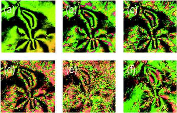
The thermal behaviour of compound 1 was studied by a combination of polarised optical microscopy (POM) and differential scanning calorimetry (DSC), its molecular structure and phase transitions are presented below in Table 1.Cooling compound 1 from the isotropic liquid affords a nematic phase, initially identified from its schlieren texture observed by POM (Fig. 1(a)). With further cooling the nematic phase takes on a mottled appearance in (Fig. 1(b)), with a predominantly green coloured texture interrupted by aperiodic pink regions. Eventually the pink domains increase in size until the texture is now predominantly comprised of those domains, (Fig. 1(d)). Further cooling yielded a phase transition at 85.6 °C into a lower temperature mesophase that also exhibited a schlieren texture, with qualitatively high fluidity and visible Brownian motion; that is to say the lower temperature phase also appears to be a nematic, denoted here as NX to distinguish it from the higher temperature phase. The schlieren texture is retained in both phases with a marked change in birefringence, whereas homeotropic regions in the higher temperature nematic phase transform to give a schlieren texture in the NX phase. At the phase transition however (Fig. 1(e)) the optical texture is complex and difficult to interpret. Initially it was thought that the two nematic phases were separated by a smectic phase, thereby introducing a reentrant nematic with the phase sequence N–Sm–NRE. After detailed analysis of the optical textures in several different geometries, we found no evidence of defects associated with smectic phases (focal-conic, fan, parabolic etc.), and as discussed later, calorimetry and X-ray scattering experiments also support this conclusion.
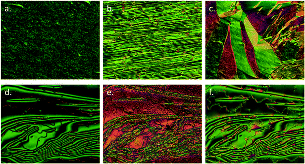
Further microscopy studies were performed on compound 1 filled in commercial cells with planar alignment layers (cell gap of 3 μm, Fig. 2a–c) and homeotropic alignment layers (cell gap of 9 μm, Fig. 2d–f). Cells were filled using capillary forces with the material in the isotropic liquid phase at ∼185 °C. When confined in 3 μm cells with a planar alignment layer the higher temperature nematic phase was well aligned (Fig. 2a). At the N–NX transition disclination lines grow approximately parallel to the rubbing direction (Fig. 2b), which gradually coalesced with decreasing temperature to give a partially aligned planar texture in the NX phase (Fig. 2c).
Compound 1 was also filled into cells with a homeotropic alignment layer, primarily to determine via conoscopy if both nematic phases were optically biaxial in their homeotropic textures. However, due to the deterioration of the alignment layer of the cells at temperatures near to the clearing point of 1 this investigation was not achieved. Instead, a conventional schlieren texture was observed in the nematic phase with 2 and 4 brush singularities being present. As with samples on untreated glass slides, the optical textures at the N–NX transition were found to be complex and difficult to interpret; being at best described as having a sanded patchy appearance. Nevertheless, the disclination lines appeared to remain throughout the sample (Fig. 2(E)). Further cooling into the NX phase afforded a schlieren texture (Fig. 2(F)) that was almost identical, aside from the markedly different birefringence, to that of the higher temperature nematic phase (Fig. 2(D)).
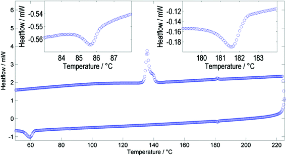
Studying compound 1 by DSC reveals two distinct phase changes; a representative DSC trace for which is presented in Fig. 3. The phase transformation has only a small associated enthalpy as would be expected if the two nematic phases have the same macroscopic symmetry. We performed additional DSC studies at various heat/cool rates between 20 °C min−1 and 1 °C−1 (data and thermograms in ESI†) and found that both the onset temperature and associated enthalpy of the NX–N and N–Iso transformations were independent of the heating/cooling rate employed. Presently we have identified 1 as having the phase sequence Iso–N–NX on cooling, with no evidence of an intervening smectic phase between the N and NX mesophases. At low heat/cool rates the NX–N phase transformation remains a single event – if a latent smectic phase was present the broad peak shown in Fig. 3 would be expected to be resolved into two peaks – and therefore demonstrates that there is a direct transformation of one nematic mesophase into another.
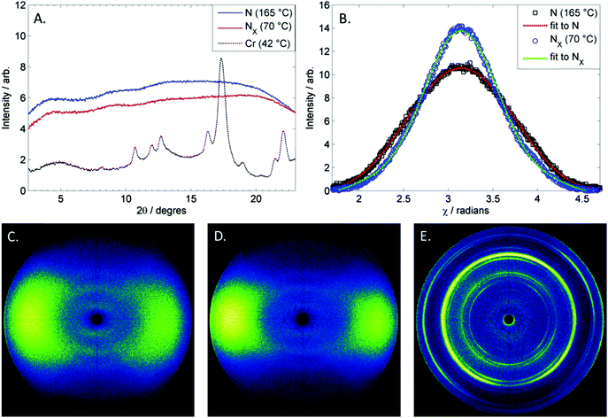
Thus, we elected to use small angle X-ray scattering to demonstrate that both the higher and lower temperature mesophases are nematic, see Fig. 4. Both the higher and lower temperature nematic phases of 1 exhibit weak scattering in the small angle region (see Fig. 4C and D) possibly due to molecular and cybotactic fluctuations of other phases (smectic) in the nematic phase. Therefore in order to obtain useful SAXS data we required relatively long exposure times (240 seconds) and as a consequence of this longer than usual exposure time the sample readily crystallised during controlled cooling cycles, however we could typically collect a single SAXS frame at any given temperature following rapid cooling. At no point did we observe the sharp small angle scattering that is the universal SAXS feature associated with smectic phases. It was observed that both the nematic (Fig. 4C) and NX (Fig. 4D) have similar scattering patterns, with both phases lacking a sharp scattering peak that would be present if either phase was smectic. The maximum intensity of the small angle peak is at 2θ ∼ 4.5, which corresponds to a d-spacing of 19.6 Å. This is shorter than the molecular length, calculated to be 21.9 Å at the B3LYP/6-31G(d) level of DFT.
In the wide-angle scattering region there are some differences between the two phases; the scattering in the nematic phase being less intense and more diffuse than that of the lower temperature NX phase. The orientational order parameters were determined for both phases of 1via the method of Davidson et al.13 at temperatures of 165° and 70 °C, obtaining values of 0.45 and 0.58 for the nematic and NX phases respectively (data fits are shown in Fig. 4B). Unfortunately, due to the tendency of compound 1 to crystallise during study, it is not clear if the order parameter at the N–NX transformation exhibits a continuous or discontinuous change.
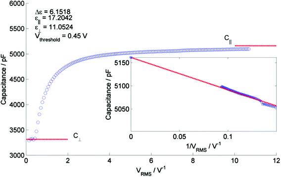
Having established that the lower temperature phase is indeed nematic-like we opted to explore how the two phases differ in their responses to applied electric fields. Under applied electric fields a Fréedericksz transition was observed in both the nematic and NX phases of 1, with a threshold voltage of ∼0.3 V and ∼0.45 V for the N and NX phases respectively (triangular waveform and a frequency in the range of 0.1–20 Hz), see Fig. 5. In terms of response to applied electric fields, the lower temperature phase behaves as would be expected for a typical nematic. Using an ACLT property tester, the capacitance of 1 at two temperatures (165 °C and 70 °C, matching those used during SAXS studies) was determined as a function of applied voltage (0.2 V steps, triangular waveform at a frequency of 1 Hz) when confined in a 2.78 μm cell treated to give planar alignment (cell purchased from INSTEC, thickness determined by UV-vis interferometry, capacitance of empty cell was 300 pF). Fitting the resulting CV curves gave values of capacitance parallel (C‖) and perpendicular (C⊥) to the director, which was used to obtain the dielectric anisotropy (Δε) and its components (ε‖ and ε⊥) as well as giving accurate values of the switching threshold voltage (Vth). The obtained values of the dielectric anisotropy were ∼8.5 in the N phase at 165 °C and ∼6.2 in the NX phase at 75 °C, which were lower than expected.
In the Maier–Meier equations the effective dipole moment (μeff) is the molecular dipole moment (μmol) attenuated by the Kirkwood ‘g’ factor, which is a simple descriptor of the degree of antiparallel/parallel correlations between molecules in a liquid crystal. Taking dipole moments and polarisabilities calculated for compound 1 at the B3LYP/6-31G(d) level of DFT in conjunction with order parameter values obtained via SAXS (and validated by electrooptic methods) we obtained solutions to the Maier–Meier equations (eqn (1)–(3)), varying the Kirkwood factor until our calculated value matched that determined experimentally. This provides a semi-empirical value of g at both temperatures studied and thereby giving insight into the antiparallel (or parallel) correlations that exist in the bulk liquid crystal phase (see eqn (1)–(3) below and the ESI† for a more detailed discussion).14–19
 | (1) |
 | (2) |
 | (3) |
Using this approach we find g ∼ 0.262 in the upper temperature nematic phase, whereas in the NX phase at 75 °C g ∼ 0.117. This result confirms that the degree of antiparallel pairing is greater in the lower temperature nematic phase than in the high temperature phase, and is a satisfactory explanation for the lower dielectric anisotropy. It should be noted that the extent of antiparallel pairing in the upper temperature nematic phase is also rather large, with a significant degree of pairing. To test this view we recorded FT-IR spectra of compound 1 in both the upper and lower temperature nematic phases (165 °C and 75 °C respectively, see Fig. S1 in the ESI†), however, no real difference was found between the FT-IR spectra in the N and NX phases, and we conclude the lack of difference between the two spectra is probably due to the extensive pairing of molecules that exists in the higher temperature phase, which is implied from analysis of dielectric data and calculation of the Kirkwood factors.
A nematic–nematic phase transition has been predicted to occur in highly polar rod-like materials when there is a cross over from antiparallel pairing to parallel pairing, driven by dipole-induced dipole and chain–chain dispersion at higher densities (i.e. lower temperature).20 As demonstrated by analysis of the Kirkwood factor the degree of antiparallel pairing is higher in the lower temperature nematic phase, and thus this model is not applicable to the present observation.
Discussion
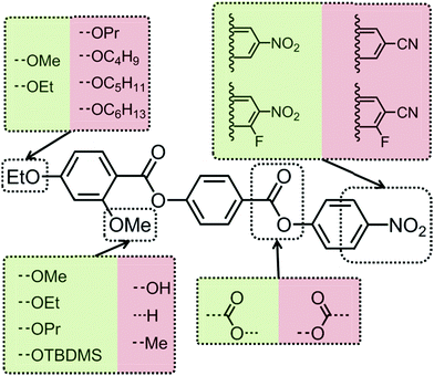
The monotropic nature of the NX phase makes detailed study of this material difficult, not only under applied fields but by SAXS and microscopy. Thus in order to improve upon the accessibility of the N–NX transformation, we are presently investigating property–structure correlations, as shown in Fig. 6. Present results indicated that the nematic phase behaviour is quite sensitive to changes to molecular architecture. For example, the NX phase is only observed for short terminal chains (OMe and OEt) and when a sufficiently large lateral group (methoxy or larger) is present. Reversal of one of the carboxylate esters leads to a material that is only nematogenic, as does the removal of this linking unit to give a biphenyl benzoate mesogen. The molecular dipole moment can be increased by positioning a fluorine atom ortho to the terminal nitro group, without detriment to the incidence of the lower temperature nematic phase. However, replacement of the nitro group with a nitrile moiety apparently suppresses this phase behaviour, probably due to the reduced tendency for antiparallel pair formation.19From these correlations it is apparent that a large longitudinal dipole moment is a clue to the possible origins of this lower temperature nematic phase. It is well-known that highly polar liquid crystals tend to organise into antiparallel pairs and it is reasonable to assume – if not implied based on measurement of dielectric anisotropy and calculation of the semi-empirical Kirkwood factor – that there is extensive antiparallel pairing in both “nematic” phases of compound 1, mirroring behaviour seen in other polar rod-like liquid crystals, such as the cyanobiphenyls, and the related reentrant nematic behaviour they exhibit in mixtures, and the compound DB9ONO2 which is multiply reentrant (see Fig. 7).
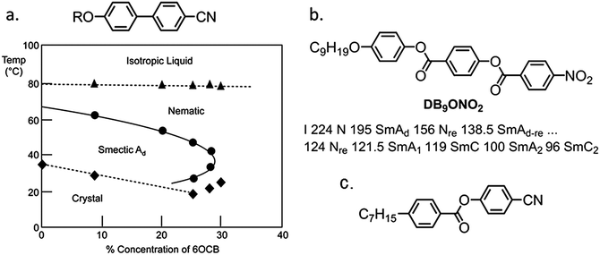 | ||
| Fig. 7 (a) Partial phase diagram of the alkoxycyanobiphenyl materials 6OCB (R = H13C6−) and 8OCB (R = H17C8−) with transition temperatures (°C) given as a function of the concentration of 6OCB in 8OCB; triangles correspond to N–I transitions, circles to SmA–N or Nre–SmA and diamonds to melting points.6 (b the molecular structure and phase transitions (°C) of 4-nonyloxyphenyl 4-(4′-nitrobenzoyloxy)benzoate (DB9ONO2)) which exhibits multiple nematic and smectic A phases.21 (c) The molecular structure of CP7B which has been reported to exhibit a N–N transition.26 | ||
The reentrant phase behaviour of DB9ONO2 was described as being competitively dependent on the commensurate versus incommensurate packing of monomeric and dimeric packing arrangements of the molecules.21–23 The reentrant behaviour of the binary mixtures of certain cyanobiphenyls was also based upon the competition between dimeric versus monomeric arrangements in the molecular packing.6 Experimental studies on the physical properties of the nematic phase of mixtures close to the turnaround point in the smectic phase in the binary phase diagrams (for example 30% concentration of 6OCB in Fig. 7) showed that the nematic phase exhibited discontinuities in properties, e.g. viscosity, elastic constants etc.24,25 In comparison compound 1 possesses a similar structure to DB9ONO2, but additionally it has a lateral methoxy unit, which induces lateral separation between the molecules thereby suppressing smectic mesophase formation. As a consequence, the nematic to reentrant nematic phase sequence minus the smectic phase occurs for compound 1. Thus compound 1 remarkably exhibits a nematic to ‘reentrant nematic’ transformation in a pure material. This explanation may also suffice for the polar calamitic liquid-crystalline compound CP7B (Fig. 7c), which has been reported to exhibit a nematic–nematic transition.26 Assuming this to be correct it is to be expected that approaching the N–NX phase transition in 1 and related materials the physical properties will exhibit a discontinuous change akin to that experienced on going from a nematic to a smectic mesophase. In the case of 1 there is perhaps a transient attempt to form a smectic phase but due to the short terminal chains the material only exhibits nematic mesophases and thus the N–NX transition is observed.
Investigating this possibility, as described in the above sections, we considered the commensurate and incommensurate packing arrangements of the molecules for compound 1. It was found that the degree of pairing increases with decreasing temperature until the concentration of unpaired molecules reaches a critical value, which then leads to the nematic to nematic transformation. Thus the effective molecular length in the higher-temperature nematic phase is related to that of a single molecule (and the order parameter), whereas in the lower-temperature phase it is related to the length of the antiparallel pair and the order parameter that dictates the effective molecular length. Consequently, it will be possible to differentiate between the two nematics based on the small angle scattering peak in resonant SAXS experiments, thereby giving further insights into the local structure of the lower temperature phase.
The local structure and director organisation of the lower temperature nematic phase are unknown; however, given the similarities in behaviour (POM, SAXS and applied electric fields) the present assignment of the lower temperature phase as being a bona fide nematic is not contentious as the high and low temperature nematic phases have the same symmetry. Moreover, because of the similarities in optical textures, SAXS patterns, and responses to applied fields, it appears at this stage that the upper- and lower-temperature nematic phases are not especially different in terms of local structure or in properties away from the point of transformation.
Thus, the two phases are separated by a phase transformation of fairly small enthalpy (ΔH = 0.2 kJ mol−1), the order parameter is somewhat higher in the lower temperature nematic phase than the higher temperature phase, where the dielectric anisotropy is significantly lower. It is therefore to be expected that the dielectric anisotropy, elastic constants and Kirkwood ‘g’ factor will exhibit discontinuous changes at the nematic to nematic transformation, as opposed to a continuous change.
Conclusions
We have discovered an example of a nematic-to-nematic transformation in a highly polar calamitic (rod-like) liquid crystal. At the change over from one nematic variation to the other there appears to be a transient attempt to form a smectic phase as the proportion of antiparallel arrangements of the molecules in the phase becomes critical. The formation of a smectic phase is probably prevented by the steric repulsion of the lateral methoxy side group. Despite thorough investigation by microscopy, calorimetry and SAXS we find no evidence for a latent smectic mesophase and conclude that the phase transformation is one between a conventional nematic and a quasi-reentrant nematic. At the crossover the physical properties alter markedly, but within the temperature range of both of the nematics, they are structurally the same, with the same macroscopic symmetry which manifests in the low enthalpy associated with the phase transformation.Author contribution statement
RJM synthesised all compounds and performed experimental work. All authors contributed equally to the writing of the manuscript.Competing financial interests statement
The authors declare no competing financial interests.Acknowledgements
The authors thank QinetiQ for funding an ICASE studentship for RJM and Dr I. Sage for useful discussions. EPSRC grant EP/M020584/1 for the development of dyes for liquid crystal applications, EPSRC Platform Grant EP/D055261/1, EPSRC grant EP/J007714/1 for the development of liquid crystals for displays and lastly EPSRC core capabilities grant EP/K039660/1. Raw data pertinent to this work is available on request from the University of York.References
- I. Dozov, Europhys. Lett., 2001, 56, 247–253 CrossRef CAS.
- M. Sepelj, A. Lesac, U. Baumeister, S. Diele, H. L. Nguyen and D. W. Bruce, J. Mater. Chem., 2007, 17, 1154–1165 RSC.
- R. J. Mandle, Soft Matter, 2016, 12, 7883–7901 RSC.
- D. Chen, J. H. Porada, J. B. Hooper, A. Klittnick, Y. Shen, M. R. Tuchband, E. Korblova, D. Bedrov, D. M. Walba, M. A. Glaser, J. E. Maclennan and N. A. Clark, Proc. Natl. Acad. Sci. U. S. A., 2013, 110, 15931–15936 CrossRef CAS PubMed.
- S. Chandrasekhar, Liq. Cryst., 1993, 14, 3–14 CrossRef CAS.
- P. E. Cladis, D. Guillon, F. R. Bouchet and P. L. Finn, Phys. Rev. A: At., Mol., Opt. Phys., 1981, 23, 2594–2601 CrossRef CAS.
- L. A. Madsen, T. J. Dingemans, M. Nakata and E. T. Samulski, Phys. Rev. Lett., 2004, 92, 145506 CrossRef PubMed.
- B. R. Acharya, A. Primak and S. Kumar, Phys. Rev. Lett., 2004, 92, 145505 CrossRef PubMed.
- J. A. C. Veerman and D. Frenkel, Phys. Rev. A: At., Mol., Opt. Phys., 1992, 45, 5632–5648 CrossRef.
- A. Zep, S. Aya, K. Aihara, K. Ema, D. Pociecha, K. Madrak, P. Bernatowicz, H. Takezoe and E. Gorecka, J. Mater. Chem. C, 2013, 1, 46–49 RSC.
- C. T. Archbold, E. J. Davis, R. J. Mandle, S. J. Cowling and J. W. Goodby, Soft Matter, 2015, 11, 7547–7557 RSC.
- M. J. Frisch, G. W. Trucks, H. B. Schlegel, G. E. Scuseria, M. A. Robb, J. R. Cheeseman, G. Scalmani, V. Barone, B. Mennucci, G. A. Petersson, H. Nakatsuji, M. Caricato, X. Li, H. P. Hratchian, A. F. Izmaylov, J. Bloino, G. Zheng, J. L. Sonnenberg, M. Hada, M. Ehara, K. Toyota, R. Fukuda, J. Hasegawa, M. Ishida, T. Nakajima, Y. Honda, O. Kitao, H. Nakai, T. Vreven, J. A. Montgomery Jr., J. E. Peralta, F. Ogliaro, M. J. Bearpark, J. Heyd, E. N. Brothers, K. N. Kudin, V. N. Staroverov, R. Kobayashi, J. Normand, K. Raghavachari, A. P. Rendell, J. C. Burant, S. S. Iyengar, J. Tomasi, M. Cossi, N. Rega, N. J. Millam, M. Klene, J. E. Knox, J. B. Cross, V. Bakken, C. Adamo, J. Jaramillo, R. Gomperts, R. E. Stratmann, O. Yazyev, A. J. Austin, R. Cammi, C. Pomelli, J. W. Ochterski, R. L. Martin, K. Morokuma, V. G. Zakrzewski, G. A. Voth, P. Salvador, J. J. Dannenberg, S. Dapprich, A. D. Daniels,Ö. Farkas, J. B. Foresman, J. V. Ortiz, J. Cioslowski and D. J. Fox, Gaussian 09, Revision E.01, Gaussian, Inc., Wallingford CT, 2016 Search PubMed.
- P. Davidson, D. Petermann and A. M. Levelut, J. Phys. II, 1995, 5, 113–131 CrossRef CAS.
- L. Onsager, J. Am. Chem. Soc., 1936, 58, 1486–1493 CrossRef CAS.
- W. Maier and G. Meier, Z. Naturforsch., A: Phys. Sci., 1961, 16, 262–267 Search PubMed.
- B. Ringstrand, P. Kaszynski, A. Januszko and V. G. Young, J. Mater. Chem., 2009, 19, 9204–9212 RSC.
- R. Zhang, J. He, Z. H. Peng and L. Xuan, Chin. Phys. B, 2009, 18, 2885–2892 CrossRef CAS.
- P. Kaszynski, A. Januszko and K. L. Glab, J. Phys. Chem. B, 2014, 118, 2238–2248 CAS.
- R. J. Mandle, S. J. Cowling, I. Sage, M. E. Colclough and J. W. Goodby, J. Phys. Chem. B, 2015, 119, 3273–3280 CrossRef CAS PubMed.
- A. S. Govind and N. V. Madhusudana, Liq. Cryst., 1993, 14, 1539–1551 CrossRef CAS.
- F. Hardouin, M. F. Achard, C. Destrade and N. H. Tinh, J. Phys., 1984, 45, 765–769 CAS.
- E. Fontes, P. A. Heiney, J. L. Haseltine and A. B. Smith, J. Phys., 1986, 47, 1533–1539 CAS.
- J. W. Goodby, E. J. Davis, R. J. Mandle and S. J. Cowling, Isr. J. Chem., 2012, 52, 863–880 CrossRef CAS.
- A. Kubono, K. Yoshino, T. Ninomiya, R. Akiyama and K. Tanaka, Liq. Cryst., 2002, 29, 1089–1095 CrossRef CAS.
- R. J. Holden and E. P. Raynes, personal communication.
- S. R. Warrier, D. Vijayaraghavan and N. V. Madhusudana, Europhys. Lett., 1998, 44, 296–301 CrossRef CAS.
Footnote |
| † Electronic supplementary information (ESI) available. See DOI: 10.1039/c7cp00456g |
| This journal is © the Owner Societies 2017 |


