
 Open Access Article
 This Open Access Article is licensed under a Creative Commons Attribution-Non Commercial 3.0 Unported Licence
Formation of a solid solution between [N(C2H5)4][BF4] and [N(C2H5)4][PF6] in crystal and plastic crystal phases†
Kazuhiko
Matsumoto
 *,
Ryojun
Nonaka
,
Yushen
Wang
,
Gleb
Veryasov
and
Rika
Hagiwara
*,
Ryojun
Nonaka
,
Yushen
Wang
,
Gleb
Veryasov
and
Rika
Hagiwara
Department of Fundamental Energy Science, Graduate School of Energy Science, Kyoto University Sakyo-ku, Kyoto 606-8501, Japan. E-mail: k-matsumoto@energy.kyoto-u.ac.jp
First published on 8th December 2016
Abstract
The phase behavior of [N2222][BF4] and [N2222][PF6] (N2222+ = tetraethylammonium cation) binary systems has been investigated in the present study. Differential scanning calorimetry revealed that the crystal-to-plastic-crystal transition temperature decreases upon mixing the two salts, with a minimum at x([N2222][PF6]) = 0.4, where x([N2222][PF6]) denotes the molar fraction of [N2222][PF6]. Powder X-ray diffraction analysis indicated the formation of a solid solution with a rock-salt type structure in the plastic crystal phase at all ratios and the lattice parameter a changes according to Vegard's law. In the crystal phase, two solid solution phases based on the structures of the single salts are observed. Raman spectroscopy confirmed the changes in the solid–solid transition temperature as observed by differential scanning calorimetry. Consequently, in the resulting phase diagram, the solid solution is formed in a wide x([N2222][PF6]) range for both the crystal and plastic crystal phases.
Introduction
Organic salts are widely used as electrolytes in both aqueous and nonaqueous solutions due to their high electrochemical stabilities and high degrees of dissociation.1 The liquid state of organic salts in the absence of solvent is known as ionic liquid and has applications in diverse fields that utilize their unique properties.2–4 In the solid state, organic salts sometimes act as ion conductors by incorporating specific structures including globular or flexible frames, and ionic plastic crystals (IPCs) are examples of such ion conductors.5–14 Ionic plastic crystals are characterized by the highly disordered structures of the component ions, and the determination of their crystal structures is generally difficult.10,13,15–18 Such disordered structures can lead to the loss of orientational order and result in a significantly small entropy change of melting.19,20 Organic salts usually have greater structural flexibility than simple inorganic salts due to the high structural freedom in a molecular ion, resulting in complicated intra- and intermolecular interactions.High ionic conductivity and a wide temperature range are the requirements for the application of a plastic crystal phase as a solid-state electrolyte. Mixing two organic salts is an interesting strategy to attain this requirement, and potentially changes the structural and thermal properties of the framework of organic salts. This includes the lowering of the crystal-to-plastic-crystal phase transition temperature and the enhancement of ion transport in the lattice. The structures of alkylammonium and alkylphosphonium salts change along with their phase transitions upon heating, which was investigated by various techniques like differential scanning calorimetry (DSC), X-ray diffraction (XRD), and nuclear magnetic resonance (NMR).13,15,17,18,21–29 Our recent study of the tetraalkylammonium salts of BF4− and PF6− revealed that the structural type of their plastic crystal phases depends on the size of the cation, which follows the radius ratio rule.30 This indicates a highly disordered state of the component ions to satisfy the site symmetry of a crystal lattice with high symmetry. Among the five different structural types observed, a rock-salt type structure was confirmed for the plastic crystals of relatively small cations, including [N2222][BF4] and [N2222][PF6] (N2222+ = tetraethylammonium cation, see Fig. 1 for the chemical structures of N2222+, BF4−, and PF6−). Although their ionic conductivities were not high enough for application in electrochemical devices, these two salts of the same structural type can provide a good model to study the solid-solution behavior between alkylammonium salts.
 | ||
| Fig. 1 Chemical structures of N2222+, BF4− and PF6−. | ||
The formation of solid solutions between some organic salts has been reported; however, little effort has been made to elucidate the solid-solution behavior of tetraalkylammonium salts. For example, a solid solution between [N(CH3)4][MnCl3] and [N(CH3)4][CuCl3] was confirmed by dielectric measurements and displayed changes in the solid–solid phase transition temperature.31 So far, no systematic and detailed information is available for the thermal and structural changes along with solid-solution formation, especially for plastic crystal phases. This is in contrast to the addition of an inorganic salt to organic salts (or organic plastic crystal) (e.g. Li[N(SO2CF3)2]–[N-ethyl-N-methyl-pyrrolidinium][N(SO2CF3)2]),32 which is mainly carried out in order to introduce mobile ionic species to construct a battery system.
The present study reports the structural behavior of the plastic crystal phases of the [N2222][BF4]–[N2222][PF6] binary system, mainly targeting the formation of solid solutions. The structure of the crystal phase is also important in investigating the crystal–plastic crystal phase transition and is also included in this work. The phase transition and structure at each fraction of [N2222][PF6] (x([N2222][PF6])) are investigated by DSC and XRD (single-crystal and powder) measurements. Raman spectroscopy is also used to confirm the structural changes.
Experimental
Chemicals
Volatile materials were handled in a vacuum line made of stainless steel and PFA (tetrafluoroethylene–perfluoroalkylvinylether copolymer). Nonvolatile materials were handled in a glovebox under a dry Ar atmosphere, or in a dry chamber under a dry air atmosphere. [N2222][BF4] (Aldrich, purity 98%) and [N2222][PF6] (Aldrich, purity 98%) salts were purchased and dried under vacuum at 353 K. All the samples in x([N2222][PF6]) ranging from 0.1–0.9 for the [N2222][BF4]–[N2222][PF6] binary system were pelletized into a disk (10 mm in diameter and ca. 1 mm in thickness) and treated at 473 K under vacuum for 24 h to ensure the mutual diffusion of ionic species, followed by equilibration at room temperature for at least three weeks.Analysis
Differential scanning calorimetric analysis was performed under a dry Ar gas flow using a ThermoPlus EVO II DSC 8230 (Rigaku) instrument at a scanning rate of 5 K min−1. The sample was sealed in an Al cell. Enthalpy changes were calculated by integrating the heat flow during each transition in the DSC curve and entropy changes were calculated by dividing the enthalpy changes by the transition temperature. The onset and final temperatures of each transition were determined using the tangent intersection method. Raman spectra were recorded on a Nanofinder 30 (Tokyo Instruments, Inc.) instrument using the 632.8 nm excitation line of a He–Ne laser. The Raman shift was calibrated by single-crystal Si. The samples for Raman spectroscopy were loaded in an Al cell and sealed in an air-tight temperature controlled unit THMS600 (Linkham Scientific Instruments) under dry Ar. Powder XRD patterns were recorded on an Ultima IV X-ray diffractometer (Rigaku Corp.) equipped with a D/teX Ultra silicon strip detector and graphite-monochromated Cu-Kα irradiation (1.5418 Å; 40 kV–40 mA), or a SmartLAb X-ray diffractometer (Rigaku Corp.) equipped with a D/teX Ultra 250 silicon strip detector and graphite-monochromated Cu-Kα irradiation (1.5418 Å; 40 kV–30 mA). The well-ground sample was spread on a Cu holder and placed in a temperature controlling apparatus. The measurement was performed under vacuum at a scanning rate of 0.1° min−1. The obtained data were indexed using a DICVOL06 with zero-point correction.33 Single-crystal XRD data were collected on an R-axis Rapid II diffractometer (Rigaku Corp.) equipped with an imaging plate area detector (using the program RAPIDXRD 2.3.334) and graphite-monochromated Mo-Kα radiation (0.71073 Å; 50 kV–40 mA). Single crystals of [N2222][BF4]0.504[PF6]0.496 were grown by slow cooling of the acetone solution of the 1![[thin space (1/6-em)]](https://www.rsc.org/images/entities/char_2009.gif) :1 mixture of [N2222][BF4] and [N2222][PF6] from 333 K to room temperature. Cell parameters of [N2222][PF6] at 298 K were determined by single-crystal XRD. The single crystals of [N2222][PF6] were grown by repeated heating and slow cooling of the acetone solution between 298 K and 323 K. The resulting crystals were further grown at around 255 K. Suitable crystals measuring 0.4 × 0.4 × 0.6 mm3 for [N2222][BF4]0.504[PF6]0.496 and 0.1 × 0.3 × 0.4 mm3 for [N2222][PF6] were selected under a microscope and fixed in a glass capillary under a dry Ar atmosphere. Data collection consisted of 12 ω scans (130–190° and 5° frame−1) at fixed φ (0°) and χ (45°) angles and 32 ω scans (0–160° and 5° frame−1) at fixed φ (180°) and χ (45°) angles with an exposure time of 600 s deg−1. Integration, scaling, and absorption corrections were performed using RAPID AUTO 2.40.35 The structure was solved using SIR-9236 and refined using SHELXL-9737 linked to Win-GX.38 For the [N2222][BF4]0.504[PF6]0.496 structure, anisotropic displacement factors were introduced for all the atoms except hydrogen. Hydrogen atoms were determined using an appropriate riding model.
:1 mixture of [N2222][BF4] and [N2222][PF6] from 333 K to room temperature. Cell parameters of [N2222][PF6] at 298 K were determined by single-crystal XRD. The single crystals of [N2222][PF6] were grown by repeated heating and slow cooling of the acetone solution between 298 K and 323 K. The resulting crystals were further grown at around 255 K. Suitable crystals measuring 0.4 × 0.4 × 0.6 mm3 for [N2222][BF4]0.504[PF6]0.496 and 0.1 × 0.3 × 0.4 mm3 for [N2222][PF6] were selected under a microscope and fixed in a glass capillary under a dry Ar atmosphere. Data collection consisted of 12 ω scans (130–190° and 5° frame−1) at fixed φ (0°) and χ (45°) angles and 32 ω scans (0–160° and 5° frame−1) at fixed φ (180°) and χ (45°) angles with an exposure time of 600 s deg−1. Integration, scaling, and absorption corrections were performed using RAPID AUTO 2.40.35 The structure was solved using SIR-9236 and refined using SHELXL-9737 linked to Win-GX.38 For the [N2222][BF4]0.504[PF6]0.496 structure, anisotropic displacement factors were introduced for all the atoms except hydrogen. Hydrogen atoms were determined using an appropriate riding model.
Results and discussion
Thermal properties
Differential scanning calorimetric curves for the first heating scan of the [N2222][BF4]–[N2222][PF6] binary system (x([N2222][PF6]) = 0–1.0) are shown in Fig. 2 (see Fig. S1–S11, ESI,† for all the DSC curves). The corresponding DSC data are listed in Table 1. The pelletized samples were pre-treated at 473 K and equilibrated at room temperature prior to use (see the Experimental section for details). The DSC scan consists of an initial heating process from room temperature to 473 K, a cooling process from 473 K to 203 K, followed by a second heating process from 203 K to 473 K. In most cases, the second heating scan was not reproducible due to the slow kinetics for the transition from the high-temperature phase to the low-temperature phase. The [N2222][BF4] and [N2222][PF6] single salts exhibit only one crystal–plastic crystal phase transition at temperatures of 352 and 355 K (final temperature of transition), respectively. Although only one solid–solid transition is observed in the range of x([N2222][PF6]) = 0.1–0.9, as in the cases of the single salts, the transition temperature gradually decreases, reaching a minimum of 328 K at x([N2222][PF6]) = 0.4. Determination of the onset temperature of this transition was not simple because of the gentle deviation from the baseline at the onset point; however, careful examination determined the minimum at x([N2222][PF6]) = 0.4 again (313 K). The entropy change of the transition tends to decrease as x([N2222][PF6]) approaches 0.4. This is explained by the decrease of the enthalpy change (3.2–7.5 kJ mol−1) in spite of the small difference in the transition temperature (328–355 K). As reported in the previous work, [N2222][BF4] and [N2222][PF6] thermally decompose at 606 and 627 K along with melting.30 Thermal analysis for the 1:1 compound showed little decrease in melting and decomposition occurs at the same time.
 | ||
| Fig. 2 Differential scanning calorimetric curves of the [N2222][BF4]–[N2222][PF6] binary system (x([N2222][PF6]) = 0–1.0). Scan rate: 5 K min−1. Atmosphere: dry Ar. | ||
| x([N2222][PF6]) | T s_o/K | T s_e/K | ΔH/kJ mol−1 | ΔS/J K−1 mol−1 |
|---|---|---|---|---|
| a T s_o and Ts_e denote the onset and final temperatures of solid–solid transition. | ||||
| 0 | — | 352 | 7.5 | 22 |
| 0.1 | 327 | 348 | 5.3 | 16 |
| 0.2 | 320 | 340 | 5.1 | 16 |
| 0.3 | 314 | 333 | 5.0 | 16 |
| 0.4 | 313 | 328 | 3.2 | 10 |
| 0.5 | 317 | 331 | 3.7 | 12 |
| 0.6 | 321 | 335 | 4.5 | 14 |
| 0.7 | 325 | 339 | 3.7 | 11 |
| 0.8 | 330 | 344 | 4.6 | 14 |
| 0.9 | 335 | 352 | 5.0 | 15 |
| 1.0 | — | 355 | 5.1 | 15 |
Structures in the crystal phase
Structures of the crystal phases for the [N2222][BF4]–[N2222][PF6] binary system were analyzed by a combination of powder and single-crystal XRD. Fig. 3 shows the XRD patterns of the [N2222][BF4]–[N2222][PF6] binary system (x([N2222][PF6]) = 0–1.0) at 298 K. The observed diffraction pattern of [N2222][BF4] agrees with that of the reported monoclinic unit cell containing ordered cations and anions at room temperature39 (another disordered model is also reported at low temperature40). The diffraction pattern at x([N2222][PF6]) = 0.1 is similar to that at x([N2222][PF6]) = 0, suggesting the formation of a solid-solution phase based on the [N2222][BF4] structure ([N2222][BF4]ss). In the range of 0.3 ≤ [N2222][PF6] ≤ 0.9, the diffraction patterns are similar to those of x([N2222][PF6]) = 1.0, which indicates that BF4− randomly substitutes for PF6−, leading to the formation of solid solutions based on the [N2222][PF6] structure. At x([N2222][PF6]) = 0.2, the solid solution phase based on the [N2222][PF6] structure is dominant but weak diffraction peaks of [N2222][BF4]ss are also observed.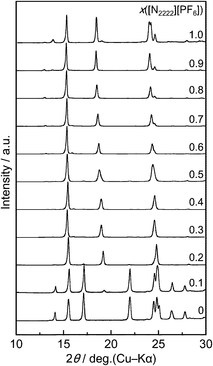 | ||
| Fig. 3 X-ray diffraction patterns of the [N2222][BF4]–[N2222][PF6] system at 298 K, in the range x([N2222][PF6]) = 0–1.0. | ||
By carefully observing the peaks in the diffraction patterns of [N2222][PF6]ss, one can note that disappearance (e.g. the peak at 13.9°), fusion (the peaks in the range of 23–25°), and shift (most peaks) occur along with the decrease in x([N2222][PF6]). Although the peak shift is explained by the substitution of the anion based on the difference in the radii of BF4− and PF6−, the disappearance/fusion of peaks possibly arises from a change in the lattice symmetry. This point was further investigated by single-crystal XRD.
The [N2222][PF6] crystal belongs to the monoclinic space group C2/c in the temperature range of 100–220 K according to a previous report.41 Single-crystal XRD in this study confirmed that the space group of [N2222][PF6] does not change even at 298 K (summarized in Table S1, ESI†) although complete structure refinement was difficult for the data at 298 K due to the high disorder of PF6−. Recrystallization of the 1:1 mixture of [N2222][BF4] and [N2222][PF6] from its acetone solution yielded crystalline materials suitable for single-crystal XRD, which revealed that this compound belongs to the tetragonal space group (I![[4 with combining macron]](https://www.rsc.org/images/entities/char_0034_0304.gif) ) at both 223 and 298 K, unlike [N2222][PF6], suggesting the formation of a solid solution, [N2222][BF4]1−x[PF6]x (Table S1, ESI†). Structural refinement at 223 K determined the crystal structure of the [N2222][BF4]0.504[PF6]0.496 solid solution as shown in Fig. 4 (the anions in the structure at 298 K were highly disordered and hard to refine fully). The structure is similar to that of the [N2222][PF6] single salt, but the crystal lattice has a higher symmetry (monoclinic for [N2222][PF6] and tetragonal for [N2222][BF4]0.504[PF6]0.496). The anion positions in this structure are randomly occupied by the tetrahedral BF4− and octahedral PF6− (see Fig. 4(a) for the packing diagram) where B and P atoms are located at the same position and F atoms in BF4− and PF6− (FB and FP) are determined in the tetrahedral and octahedral manners (Fig. 4(b)). This disorder leads to the formation of a solid solution phase with high symmetry. It should be noted that the large displacement factors for F atoms in the anions imply the potential disordering of the anions. The simulated powder diffraction pattern of [N2222][BF4]0.504[PF6]0.496 satisfactorily reproduces the experimental diffraction pattern of the [N2222][BF4]–[N2222][PF6] salt at x([N2222][PF6]) = 0.5 (Fig. S12 (ESI†) the shift between the patterns results from the difference in measurement temperature). This is in contrast to the simulated pattern for [N2222][PF6], which confirms that the powder obtained at x([N2222][PF6]) = 0.5 belongs to the tetragonal space group. The transformation from the monoclinic [N2222][PF6] structure to the tetragonal solid solution indicated by the powder diffraction data occurs gradually along with the increase of the [N2222][BF4] fraction.
) at both 223 and 298 K, unlike [N2222][PF6], suggesting the formation of a solid solution, [N2222][BF4]1−x[PF6]x (Table S1, ESI†). Structural refinement at 223 K determined the crystal structure of the [N2222][BF4]0.504[PF6]0.496 solid solution as shown in Fig. 4 (the anions in the structure at 298 K were highly disordered and hard to refine fully). The structure is similar to that of the [N2222][PF6] single salt, but the crystal lattice has a higher symmetry (monoclinic for [N2222][PF6] and tetragonal for [N2222][BF4]0.504[PF6]0.496). The anion positions in this structure are randomly occupied by the tetrahedral BF4− and octahedral PF6− (see Fig. 4(a) for the packing diagram) where B and P atoms are located at the same position and F atoms in BF4− and PF6− (FB and FP) are determined in the tetrahedral and octahedral manners (Fig. 4(b)). This disorder leads to the formation of a solid solution phase with high symmetry. It should be noted that the large displacement factors for F atoms in the anions imply the potential disordering of the anions. The simulated powder diffraction pattern of [N2222][BF4]0.504[PF6]0.496 satisfactorily reproduces the experimental diffraction pattern of the [N2222][BF4]–[N2222][PF6] salt at x([N2222][PF6]) = 0.5 (Fig. S12 (ESI†) the shift between the patterns results from the difference in measurement temperature). This is in contrast to the simulated pattern for [N2222][PF6], which confirms that the powder obtained at x([N2222][PF6]) = 0.5 belongs to the tetragonal space group. The transformation from the monoclinic [N2222][PF6] structure to the tetragonal solid solution indicated by the powder diffraction data occurs gradually along with the increase of the [N2222][BF4] fraction.
 | ||
| Fig. 4 (a) The packing diagram at the 30% probability level and (b) disordering of the anion for the [N2222][BF4]0.504[PF6]0.496 structure determined at 223 K. The labels, FP and FB, denote the F atoms in PF6− and BF4−, respectively (P–FP, 1.531(4)–1.536(8) Å; B–FB, 1.365(8) Å; cis-FP–P–FP, 89.9(1)–90.1(1); trans-FP–P–FP, 179.8(3)–180; FB–B–FB, 105.4(12)–111.6(6)). Hydrogen atoms are omitted for clarity. | ||
Structures in the plastic crystal phase
Fig. 5 shows the temperature dependence of the XRD pattern of the [N2222][BF4]–[N2222][PF6] salt at x([N2222][PF6]) = 0.5 from 298 K to 373 K. The tetragonal phase observed at 298 K and 313 K disappears at 348 K and another phase appears at 333 K. This structural change agrees with the DSC analysis, and a similar behavior was observed at all ratios (see Fig. S13–S22, ESI,† for the other ratios). | ||
| Fig. 5 X-ray diffraction patterns of [N2222][BF4]–[N2222][PF6] for x([N2222][PF6]) = 0.5, at 298, 313, 333, 348, and 373 K. | ||
Fig. 6(a) shows the XRD patterns of the [N2222][BF4]–[N2222][PF6] binary system (0 ≤ x([N2222][PF6]) ≤ 1.0) at 373 K. According to a previous study on the [N2222][BF4] and [N2222][PF6] single salts,30 systematic absences for the indexed cubic cells suggested that they have a rock-salt type structure in the plastic crystal phase, which was also confirmed in this study (a = 10.929(8) Å for [N2222][BF4], and a = 11.3179 (7) Å for [N2222][PF6]). The highly symmetric N2222+, BF4−, and PF6− ions can be approximated to be spherical in the plastic crystal phases. This is in contrast to the N(SO2CF3)2− salts which usually do not show a cubic or hexagonal plastic crystal lattice.10,42,43 At any ratio in the range of 0.1 ≤ x([N2222][PF6]) ≤ 0.9, the diffraction patterns exhibit five diffraction peaks (2θ < 30°) which can be indexed based on a rock-salt type structure with a monotonous shift, although the 111 diffraction peak is quite weak in the pattern for the small x([N2222][PF6]). This indicates the formation of a solid solution in this system, with the BF4− and PF6− anions randomly occupying the anionic positions in the rock-salt type plastic crystal lattice.
 | ||
| Fig. 6 (a) X-ray diffraction patterns of the [N2222][BF4]–[N2222][PF6] system at 373 K in the range x([N2222][PF6]) = 0–1.0, and (b) the lattice parameter (a) in the plastic crystal phase at different x([N2222][PF6]) values calculated from the XRD patterns. | ||
Fig. 6(b) shows the relationship between x([N2222][PF6]) and the lattice parameter (a) of the rock-salt type structure for the [N2222][BF4]–[N2222][PF6] binary system (see Table S2, ESI,† for the XRD data with indices and lattice parameters). This relation is simply expressed by the following linear equation:
| y = bx + c |
The reverse transition (plastic crystal to crystal) was monitored by XRD measurements. The sample at x([N2222][PF6]) = 0.5 was first kept at 473 K for 24 h and then at 298 K for 3 weeks. During the aging at 298 K, XRD patterns were occasionally recorded (1 d, 3 d, 1 week, 2 weeks, and 3 weeks), which revealed (Fig. S23, ESI†) that the plastic crystal phase exists after 2 weeks and disappears after 3 weeks. However, the reproducibility of this transition was not very high and it is likely influenced by external conditions such as temperature fluctuations, container materials, and probably physical shock. The DSC analysis showed that this transition occurs more easily at low temperatures (Fig. S6, ESI†).
Raman spectra of the crystal and plastic crystal phases
The crystal to plastic crystal transition was also detected by the changes in the vibrational modes. Fig. 7 shows the Raman spectra of the [N2222][BF4]–[N2222][PF6] salts (x([N2222][PF6]) = 0, 0.5, and 1.0) in the temperature range of 298–373 K (see Fig. S24–S29, ESI,† for the wider wavenumber range). Spectra in the ranges of 640–680 and 730–770 cm−1 are shown here; the former region contains the peak from the symmetric stretching mode of the cation (ν1(NC4)) and the latter displays the symmetric stretching modes of the anions (ν1(BF4−) and ν1(PF6−))46 (see Tables S2–S7, ESI,† for the spectral data). | ||
| Fig. 7 Raman spectra of [N2222][BF4]–[N2222][PF6] at x([N2222][PF6]) = 0 ((a) and (d)), 0.5 ((b) and (e)), and 1.0 ((c) and (f)). Panels (a)–(c) show the ν1(NC4) mode of the TT- and TG-conformers of N2222+; panels (d)–(f) show the ν1(BF4−) and ν1(PF6−) modes. | ||
Two stable conformers, the trans–trans (TT-, D2d symmetry) and trans–gauche (TG-, S4 symmetry) conformers, are known for N2222+.10,47,48 The ν1(NC4) modes of these two conformers exhibit slightly different frequencies (Fig. 7(a)–(c)), with the TT-conformer having a lower frequency than the TG-conformer. For both the single salts, the peak shift of the ν1(NC4) mode along with the solid–solid transition agrees with those in previous works;10,15,29,34,35 the peak is observed at the lower frequency (661.6 cm−1 for [N2222][BF4] and 660.0 cm−1 for [N2222][PF6] at 298 K) below the transition temperature, corresponding to the TG-conformer, whereas another peak at the higher frequency (671.8 cm−1 for [N2222][BF4] and 671.1 cm−1 for [N2222][PF6] at 373 K) assigned to the TT-conformer appears above the transition temperature, suggesting that the TT-conformer is dominant in the plastic crystal phase. The temperature at which the TT-conformer appears decreases when the two salts are mixed and the spectrum at 313 K includes the peak from the TT-conformer, although the TG-conformer is still dominant at this temperature. This trend matches the transition observed in the DSC analysis above.
The shift of the ν1(BF4−) and ν1(PF6−) modes occurs at the same temperature for the ν1(NC4) mode (Fig. 7(d)–(f)). For the single salts, their frequencies at 298 K (764.7 cm−1 for ν1(BF4−) and 741.5 cm−1 for ν1(PF6−)) shift to the lower frequency at 348 K (762.5 cm−1 for ν1(BF4−) and 740.0 cm−1 for ν1(PF6−)). The [N2222][BF4]–[N2222][PF6] salt at x([N2222][PF6]) = 0.5 exhibits a sign of the phase transition at 333 K and the complete shift is confirmed at 348 K. The full width at half maximum (FWHM) values of the ν1(BF4−) and ν1(PF6−) modes at 373 K are larger than those at 298 K (1.4 and 1.3 cm−1 at 373 and 298 K, respectively, for ν1(BF4−) and 1.9 and 1.7 cm−1 at 373 and 298 K, respectively, for ν1(PF6−) at x([N2222][PF6]) = 0.5), suggesting that the orientational disorder is accelerated at high temperatures.
Phase diagram
Fig. 8 shows the phase diagram of the [N2222][BF4]–[N2222][PF6] binary system based on the DSC and XRD results. In the crystal phase, the structure changes in the order of [N2222][BF4]ss, the two-phase region of [N2222][BF4]ss and [N2222][PF6]ss, and [N2222][PF6]ss, with increasing x([N2222][PF6]). There was no sign of a line compound based on the present data. The plastic crystal phase has a rock-salt type structure at all ratios, and the crystal to plastic crystal transition temperature decreases upon mixing, and reaches a minimum around x([N2222][PF6]) = 0.4. Since the [N2222][PF6]ss phase appears over a wide x([N2222][PF6]) range in the crystal phase, the two-phase region of IPC(rock-salt)ss + [N2222][PF6]ss appears on both sides of the minimum for the transition temperature between x([N2222][PF6]) = 0.3 and 0.4. | ||
| Fig. 8 Phase diagram of the [N2222][BF4]–[N2222][PF6] system based on the results of DSC and XRD analysis. Open squares and solid circles denote the onset and final temperatures of the crystal to plastic crystal phase transition. The symbol, ss, in the diagram denotes the solid solution. | ||
Consequently, the two-phase region of [N2222][BF4]ss and [N2222][PF6]ss is observed in a limited x([N2222][PF6]) range around x([N2222][PF6]) = 0.2.
The identical structure of the [N2222][BF4] and [N2222][PF6] single salts results in the formation of a solid solution at all ratios in the IPC phase. Another important factor is the similarity in the sizes of BF4− and PF6−. The volumes of BF4− and PF6− are 74 and 97 Å3, respectively, based on DFT calculations,49 and 73 and 109 Å3, respectively, based on empirical estimation.50 Such a difference is not significant in combination with the relatively large N2222+ cation (206 Å3 for the TT-conformer and 208 Å3 for the TG-conformer based on DFT calculations29 and 199 Å3 based on empirical estimation50) and can be buffered by the lattice expansion (or contraction) without changing the basic structure. The a parameter of the cubic cell at 373 K increases from 10.929(8) Å at x([N2222][PF6]) = 0 to 11.3179(7) Å at x([N2222][PF6]) = 1.0, which corresponds to an expansion of just 3.6%.
Conclusions
In the present study, the phase diagram of the [N2222][BF4]–[N2222][PF6] binary system was constructed from the results of DSC and XRD measurements, in order to investigate the solid solution phase. Both the crystal and plastic crystal phases form solid solutions and the transition temperature from the crystal phase to the plastic crystal phase decreases upon mixing the two salts. Two types of structures based on the [N2222][BF4] and [N2222][PF6] single salts appear in the crystal phase, whereas the plastic crystal phase belongs to the rock-salt-type structure at any ratio. The lattice parameter a of the rock-salt-type structure increases upon increasing the [N2222][PF6] ratio, in accordance with Vegard's law. In the crystal phase, two solid solution phases based on the structures of the single salts are observed. The change in the transition temperature was also confirmed by the shift of the ν1(NC4), ν1(BF4−), and ν1(PF6−) modes in Raman spectra.Although the present study showed only the fundamental aspects of the thermal and structural properties of the [N2222][BF4]–[N2222][PF6] binary system, the formation of a solid-solution in the plastic crystal phase was clearly shown here. This may lead to a new strategy in the design of plastic crystal electrolytes in terms of extension of the temperature range and expansion of the crystal lattice. Other binary systems between two tetraalkylammonium salts with different cations (cation mixing) could prove interesting.
Notes and references
- K. Izutsu, Electrochemistry in Nonaqueous Solutions, Wiley-VCH, 2nd Revised and Enlarged edn, 2009 Search PubMed.
- F. Endres, A. P. Abbott and D. R. MacFarlane, Electrodeposition from Ionic Liquids, Wiley-VCH, Weinheim, Germany, 2008 Search PubMed.
- J. P. Hallett and T. Welton, Chem. Rev., 2011, 111, 3508–3576 CrossRef CAS PubMed.
- M. Armand, F. Endres, D. R. MacFarlane, H. Ohno and B. Scrosati, Nat. Mater., 2009, 8, 621–629 CrossRef CAS PubMed.
- J. M. Pringle, Phys. Chem. Chem. Phys., 2013, 15, 1339–1351 RSC.
- J. M. Pringle, P. C. Howlett, D. R. MacFarlane and M. Forsyth, J. Mater. Chem., 2010, 20, 2056–2062 RSC.
- E. I. Cooper and C. A. Angell, Solid State Ionics, 1986, 18–19, 570–576 CrossRef CAS.
- Y. Abu-Lebdeh, P. J. Alarco and M. Armand, Angew. Chem., Int. Ed., 2003, 42, 4499–4501 CrossRef CAS PubMed.
- D. R. MacFarlane and M. Forsyth, Adv. Mater., 2001, 13, 957–966 CrossRef CAS.
- W. A. Henderson, M. Herstedt, V. G. Young, S. Passerini, H. C. De Long and P. C. Trulove, Inorg. Chem., 2006, 45, 1412–1414 CrossRef CAS PubMed.
- W. A. Henderson, V. G. Young, S. Passerini, P. C. Trulove and H. C. De Long, Chem. Mater., 2006, 18, 934–938 CrossRef CAS.
- H. B. Han, J. Nie, K. Liu, W. K. Li, W. F. Feng, M. Armand, H. Matsumoto and Z. B. Zhou, Electrochim. Acta, 2010, 55, 1221–1226 CrossRef CAS.
- J. S. Luo, A. H. Jensen, N. R. Brooks, J. Sniekers, M. Knipper, D. Aili, Q. F. Li, B. Vanroy, M. Wubbenhorst, F. Yan, L. Van Meervelt, Z. G. Shao, J. H. Fang, Z. H. Luo, D. E. De Vos, K. Binnemans and J. Fransaer, Energy Environ. Sci., 2015, 8, 1276–1291 CAS.
- J. S. Luo, O. Conrad and I. F. J. Vankelecom, J. Mater. Chem. A, 2013, 1, 2238–2247 CAS.
- M. Herstedt, W. A. Henderson, M. Smirnov, L. Ducasse, L. Servant, D. Talaga and J. C. Lassegues, J. Mol. Struct., 2006, 783, 145–156 CrossRef CAS.
- H. Ono, R. Ikeda and H. Ishida, Ber. Bunsen-Ges., 1996, 100, 1833–1838 CrossRef CAS.
- H. Ishida, Y. Furukawa, S. Kashino, S. Sato and R. Ikeda, Ber. Bunsen-Ges., 1996, 100, 433–439 CrossRef CAS.
- L. Y. Jin, K. M. Nairn, C. M. Forsyth, A. J. Seeber, D. R. MacFarlane, P. C. Howlett, M. Forsyth and J. M. Pringle, J. Am. Chem. Soc., 2012, 134, 9688–9697 CrossRef CAS PubMed.
- S. Forsyth, J. Golding, D. R. MacFarlane and M. Forsyth, Electrochim. Acta, 2001, 46, 1753–1757 CrossRef CAS.
- J. Golding, N. Hamid, D. R. MacFarlane, M. Forsyth, C. Forsyth, C. Collins and J. Huang, Chem. Mater., 2001, 13, 558–564 CrossRef CAS.
- T. G. Coker, J. Ambrose and G. J. Janz, J. Am. Chem. Soc., 1970, 92, 5293–5297 CrossRef CAS.
- G. Zabinska, P. Ferloni and M. Sanesi, Thermochim. Acta, 1988, 137, 39–49 CrossRef CAS.
- G. Zabinska, P. Ferloni and M. Sanesi, Thermochim. Acta, 1987, 122, 87–94 CrossRef CAS.
- J. Levkov, W. Kohr and R. A. Mackay, J. Phys. Chem., 1971, 75, 2066–2069 CrossRef.
- W. H. J. Debeer, A. M. Heyns, P. W. Richter and J. B. Clark, J. Solid State Chem., 1981, 36, 171–178 CrossRef CAS.
- A. Xenopoulos, A. H. Narten, J. L. Cheng and B. Wunderlich, J. Non-Cryst. Solids, 1991, 131, 113–119 CrossRef.
- H. Ishida, Y. Furukawa, Y. Kubozono and R. Ikeda, Phys. Status Solidi A, 1994, 141, K89–K91 CrossRef CAS.
- T. Enomoto, S. Kanematsu, K. Tsunashima, K. Matsumoto and R. Hagiwara, Phys. Chem. Chem. Phys., 2011, 13, 12536–12544 RSC.
- K. Matsumoto, T. Okawa and R. Hagiwara, Chem. Lett., 2012, 41, 394–396 CrossRef CAS.
- K. Matsumoto, U. Harinaga, R. Tanaka, A. Koyama, R. Hagiwara and K. Tsunashima, Phys. Chem. Chem. Phys., 2014, 16, 23616–23626 RSC.
- K. Gesi, J. Phys. Soc. Jpn., 1993, 62, 3805–3808 CrossRef CAS.
- D. R. MacFarlane, J. H. Huang and M. Forsyth, Nature, 1999, 402, 792–794 CrossRef CAS.
- A. Boultif and D. Louer, J. Appl. Crystallogr., 2004, 37, 724–731 CrossRef CAS.
- Rigaku Corporation Tokyo, Japan, 1999-2004.
- Rigaku Corporation, Tokyo, Japan, 2006.
- A. Altomare, G. Cascarano, C. Giacovazzo and A. Guagliardi, J. Appl. Crystallogr., 1993, 26, 343–350 CrossRef.
- G. M. Sheldrick, Acta Crystallogr., Sect. A: Found. Crystallogr., 2008, 64, 112–122 CrossRef CAS PubMed.
- L. J. Farrugia, J. Appl. Crystallogr., 1999, 32, 837–838 CrossRef CAS.
- G. Giuseppetti, C. Tadini, P. Ferloni, G. Zabinska and S. Torre, Z. Kristallogr., 1994, 209, 509–511 CAS.
- J. R. de Menezes Vicenti, R. C. Scaravelli and R. A. Burrow, Private Communication on CCDC, 2008, CCDC No. 687389.
- W. Beichel, U. P. Preiss, B. Benkmil, G. Steinfeld, P. Eiden, A. Kraft and I. Krossing, Z. Anorg. Allg. Chem., 2013, 639, 2153–2161 CrossRef CAS.
- W. A. Henderson, D. M. Seo, Q. Zhou, P. D. Boyle, J. H. Shin, H. C. De Long, P. C. Trulove and S. Passerini, Adv. Energy Mater., 2012, 2, 1343–1350 CrossRef CAS.
- M. Forsyth, T. Chimdi, A. Seeber, D. Gunzelmann and P. C. Howlett, J. Mater. Chem. A, 2014, 2, 3993–4003 CAS.
- L. Vegard, Z. Phys., 1921, 5, 17–26 CrossRef CAS.
- L. Zhang and S. C. Li, Physica B, 2014, 434, 38–43 CrossRef CAS.
- K. Nakamoto, Infrared and Raman Spectra of Inorganic and Coordination Compounds, John Wiley & Sons, Inc., New York, 1997 Search PubMed.
- C. Naudin, F. Bonhomme, J. L. Bruneel, L. Ducasse, J. Grondin, J. C. Lassegues and L. Servant, J. Raman Spectrosc., 2000, 31, 979–985 CrossRef CAS.
- H. V. Brand, L. A. Curtiss, L. E. Iton, F. R. Trouw and T. O. Brun, J. Phys. Chem., 1994, 98, 1293–1301 CrossRef CAS.
- K. Matsumoto and R. Hagiwara, J. Electrochem. Soc., 2010, 157, A578–A581 CrossRef CAS.
- H. D. B. Jenkins, H. K. Roobottom, J. Passmore and L. Glasser, Inorg. Chem., 1999, 38, 3609–3620 CrossRef CAS PubMed.
Footnote |
| † Electronic supplementary information (ESI) available: Differential scanning calorimetric, Powder and single-crystal X-ray diffraction, and Raman spectroscopic data. CCDC 1517064. For ESI and crystallographic data in CIF or other electronic format see DOI: 10.1039/c6cp07992j |
| This journal is © the Owner Societies 2017 |