 Open Access Article
Creative Commons Attribution 3.0 Unported Licence
The role of metal–support interaction for CO-free hydrogen from low temperature ethanol steam reforming on Rh–Fe catalysts†
Catherine K. S.
Choong
ab,
Luwei
Chen
*a,
Yonghua
Du
a,
Martin
Schreyer
a,
S. W.
Daniel Ong
a,
Chee Kok
Poh
 a,
Liang
Hong
b and
Armando
Borgna
*a
aInstitute of Chemical and Engineering Sciences, Agency for Science, Technology, and Research (A*STAR), 1 Pesek Rd., Jurong Island, Singapore 627833, Singapore. E-mail: chen_luwei@ices.a-star.edu.sg; armando_borgna@ices.a-star.edu.sg; Tel: +65-6796-3812 Tel: +65-6796-3802
bDepartment of Chemical and Biomolecular Engineering, National University of Singapore, 10 Kent Ridge Crescent, Singapore 119260, Singapore
First published on 7th November 2016
Abstract
Rh–Fe catalysts supported on Ca–Al2O3, MgO and ZrO2 were evaluated in ethanol steam reforming at 623 K and compared to Rh catalysts on the same supports without iron promotion. The metal–support interaction among the three entities, i.e. Rh ↔ Fe2O3 ← support (ZrO2, MgO and Ca–Al2O3) was investigated using H2-chemisorption, TEM, XPS and in situ techniques such as DRIFTS, temperature-resolved XRD and XAS. As compared to the unpromoted Rh catalysts on the same supports, the CO selectivity is depressed in the presence of iron on Rh/MgO and Rh/Ca–Al2O3, the latter being significantly superior. The role of metal–support interaction for CO-free hydrogen generation was unravelled using a combination of techniques. It was found that the reducibility of iron oxide determines the extent of the strong metal support interaction between Rh and Fe2O3 and the reducibility of iron oxide was affected by the support. On Rh–Fe/Ca–Al2O3, a good balance of the interaction between Rh, Fe2O3 and Ca–Al2O3 prevents strong metal support interaction between Rh and Fe2O3 and thus promotes CO elimination via water–gas-shift reaction on Rh–FexOy sites.
1. Introduction
CO-free hydrogen production is important for proton exchange membrane fuel cells (PEMFC). Ethanol steam reforming (ESR, eqn (R1)) is a potential way to provide CO free hydrogen for PEMFC since CO removal is thermodynamically favorable at low temperature. Several research groups have shown high potential in achieving CO-free H2 production at low temperature. For example, Llorca et al. developed a carbonyl-derived Co/ZnO catalyst for CO-free hydrogen from ESR, which is fairly stable for at least 75 h at 623 K.1 A Ni/Y2O3 catalyst developed by Sun et al. was capable to produce CO free H2 for 49 h at 623 K.2 Zhang et al. used skeletal Ni-based catalysts for low temperature ethanol steam reforming and found that it had higher H2 selectivity and no CO was detected compared to conventional supported catalysts.3 However, in a real reaction, low temperature ESR (T < 450 °C) is under kinetic control and reactions such as ethanol decomposition, dehydration and dehydrogenation may occur (eqn (R2)–(R4)), depending on the catalyst and the reaction conditions used. CO can be produced from decomposition of ethanol (eqn (R2)) or from decarbonylation of reaction intermediate such as acetaldehyde (eqn (R5)), particularly on noble metals which are more active for the cleavage of C–C bond at low temperature.4,5 However, compared to Ni and Co, noble metals benefit from their low reduction temperatures and higher resistance against sintering and coking.| CH3CH2OH + 3H2O ↔ 2CO2 + 6H2 | (R1) |
| C2H5OH ↔ CH4 + CO + H2 | (R2) |
| C2H5OH ↔ C2H4 + H2O | (R3) |
| C2H5OH ↔ CH3CHO + H2 | (R4) |
| CH3CHO ↔ CO + CH4 | (R5) |
| CO + H2O ↔ CO2 + H2 | (R6) |
An iron oxide promoted Rh catalyst supported on Ca–Al2O3, reported by our group, is the only noble metal based catalyst to date, which can effectively produce CO-free hydrogen from ESR for 288 h without deactivation at low temperature of 623 K.6 It has been identified that the close proximity between Rh, iron oxide and Ca–Al2O3 support is required to reduce CO selectivity via water–gas shift reaction (WGSR, eqn (R6)) during ESR.6,7 The synergistic effect between Rh and iron oxide leads to partially reduced iron oxides FexOy species, which are the precursors for the formation of coordinatively unsaturated ferrous (CUF) sites at the Rh–FexOy interface.6 When ethanol is being activated on Rh, these CUF sites facilitate the migration of CO from Rh to iron oxide, then undergoing a facile conversion to CO2 and H2 through formate species. However, questions on how Rh is affected by iron oxide and whether Ca–Al2O3 is a unique support for the generation of Rh–FexOy active sites remain unanswered.
Many studies have been undertaken to study the interaction between iron oxide and supported metals.8–10 For example, Pd and Pt supported on iron oxides were found to be very active for CO oxidation due to strong metal support interaction (SMSI) between the metals and iron oxides.8,11 Migration of partially reduced iron oxide encapsulates the active Pt/Pd and reduces the capacity of CO/H2 adsorption of Pt/Pd.8 However, the activity was increased compared to Pt/Pd supported on unreducible oxides, such as Al2O3 and SiO2.8 Surface encapsulation of supported metals by partially reduced iron oxide has been observed through TEM and STM on both model and synthesized noble metals/iron oxide catalysts in SMSI state.11,12 There are also reports where interaction between the supported metal and iron oxide only occurs at the interfaces.9 For example, interface confinement of coordinatively unsaturated ferrous sites between FeO and Pt has been proven as the active sites for CO oxidation and the activity is proportional to the periphery density of FeO nanoislands.9
SMSI effect has been reported over Rh and some reducible oxides, such as TiO2, V2O5 and CeO2.13,14 On Rh/V2O5 and Rh/CeO2, a sub-monolayer of VOx and CeOx promote CO hydrogenation, but the reaction rates depends on the extent of SMSI and reduction temperature.14 Studies on Rh/Fe2O3 interaction have been, however, less often reported. In this contribution, a series of Rh–Fe catalysts supported on Ca–Al2O3, MgO and ZrO2 was studied for low temperature ESR. Various characterization techniques such as X-ray photoelectron spectroscopy, in situ temperature-resolved X-ray diffraction, in situ X-ray absorption spectroscopy, in situ diffuse reflectance infrared Fourier transform spectroscopy, allow us to get a better understanding on the interaction between the reducible iron oxide and the support as well as on the interaction of iron oxide with Rh. The support effect on the formation of the Rh–FexOy active sites is also unraveled and discussed.
2. Experimental
2.1. Catalyst preparation
Rh–Fe/Ca–Al2O3 catalysts were prepared by a sequential incipient wetness impregnation method, according to the following steps: (1) Ca-modified alumina, denoted as Ca–Al2O3, was prepared by the calcination of a paste of γ-Al2O3 (Merck) impregnated with a Ca(NO3)2·4H2O (Riedel–deHaën) solution corresponding to 3 wt% Ca loading. The addition of Ca reduces the acidity of Al2O3 and increases surface hydroxyls on the Al2O3 support for coke removal;15 (2) the obtained Ca–Al2O3 powder was impregnated with an appropriate amount of Fe(NO3)3 solution to obtain a precursor with 10 wt% Fe loading. The precursor was dried at 393 K for 10 h and heated up to 723 K in air and then held at this temperature for 5 h; (3) Rh (1 wt%) was introduced by impregnation with a RhCl3 solution (Alfa Aesar) onto the modified support obtained in step (2). The obtained catalyst precursor was dried and calcined as indicated in step (2) and the catalyst was denoted as Rh–Fe/Ca–Al2O3. Similar synthesis method was adopted to prepare Rh–Fe/MgO (Sigma Aldrich) and Rh–Fe/ZrO2 (Spectro). For comparison, Fe-free 1 wt% Rh catalysts, denoted as Rh/Ca–Al2O3, Rh/MgO and Rh/ZrO2, were also prepared.2.2. Catalyst evaluation
The catalytic evaluation was performed at 623 K in a customized 5-channels quartz micro-reactor (BEL, Japan), each of which was loaded with 100 mg of catalyst. The temperature of the samples was individually monitored with thermocouples located just at the top of the catalyst samples.Rh-based catalysts were reduced in hydrogen at 473 K for 0.5 h. Then 40 mL min−1 of Ar was fed into the reactor, along with 0.005 mL min−1 of ethanol–water mixture (1![[thin space (1/6-em)]](https://www.rsc.org/images/entities/char_2009.gif) :
:![[thin space (1/6-em)]](https://www.rsc.org/images/entities/char_2009.gif) 10 molar ratio), injected using a Shimadzu Liquid Pump and vaporized at 443 K within the reactor. The total gas hourly space velocity (GHSV) was kept constant at 34
10 molar ratio), injected using a Shimadzu Liquid Pump and vaporized at 443 K within the reactor. The total gas hourly space velocity (GHSV) was kept constant at 34![[thin space (1/6-em)]](https://www.rsc.org/images/entities/char_2009.gif) 000 h−1, using a mass flow controller. The reaction products were analyzed online using a gas chromatograph (Varian CP-3800) with three columns: Porapak Q, Haysep Q and molecular sieve 5A. Porapak Q was used to separate organics and carbon dioxide with He as carrier gas, while the other two columns were used for the separation of hydrogen, carbon monoxide and methane with Ar as carrier gas. The products were analyzed using two thermal conductivity detectors. The ethanol conversion (XEtOH) and selectivity to carbon containing species (SCi) were calculated based on eqn (1) and (2), respectively:
000 h−1, using a mass flow controller. The reaction products were analyzed online using a gas chromatograph (Varian CP-3800) with three columns: Porapak Q, Haysep Q and molecular sieve 5A. Porapak Q was used to separate organics and carbon dioxide with He as carrier gas, while the other two columns were used for the separation of hydrogen, carbon monoxide and methane with Ar as carrier gas. The products were analyzed using two thermal conductivity detectors. The ethanol conversion (XEtOH) and selectivity to carbon containing species (SCi) were calculated based on eqn (1) and (2), respectively:
 | (1) |
 | (2) |
In order to measure the apparent activation energy, ESR reactions were performed between 573 K and 648 K, with steam/ethanol ratio = 10, W/F = 28 kg s mol−1 and molar flow rate of ethanol = 2.2 × 10⁻⁵ mol min−1 over catalysts with particle size between 56 μm to 125 μm. The ethanol conversions were kept between 20–70%. These reaction conditions were optimized in order to avoid any contribution of homogeneous phase reaction and to minimize any external and internal diffusion limitation. The temperature gradient effect was minimized by diluting the catalyst with SiC with the same particle size within the catalytic bed.
2.3. Catalyst characterization
Brunauer, Emmett and Teller (BET) specific surface areas were measured by nitrogen adsorption at 77 K using Autosorb-IC, Quantachrome Instruments. Prior to the measurement, the catalysts were outgassed and heated at 473 K overnight. Transmission electron microscopy (TEM) micrographs were acquired using Fei Tecnai G2 TF20 S-twin microscope. High-angle annular dark field (HAADF) images were obtained in an FEI Titan 80/300 TEM (200 kV).The metallic surface areas and dispersions of Rh and Rh–Fe catalysts were determined by static measurement of H2-chemisorption at 308 K using a Micromeritics ASAP 2020C. The samples were first dried in vacuum at 523 K for 0.5 h, followed by a reduction treatment in H2 flow at 523 K for 0.5 h. Subsequently, the samples were evacuated at the same temperature for 0.5 h before cooling down to 308 K in vacuo. The particle sizes were calculated assuming hemispherical particle geometry and an H/Rh adsorption stoichiometry of 1.
In situ diffuse reflectance infrared Fourier transform spectroscopy (DRIFTS) spectra were recorded after CO adsorption using a Bio-Rad FTIR 3000 MX instrument equipped with a high-temperature cell fitted with KBr windows and a mercury–cadmium–telluride (MCT-A) detector. Prior to the DRIFTS measurement, the catalyst was reduced in H2 (50 mL min−1) at 473 K for 2 h. Following this, the sample was cooled down to room temperature in flowing He (50 mL min−1). At 303 K, 2% CO/He (50 mL min−1) was introduced into the reaction cell for 0.5 h. Spectra were recorded with a resolution of 4 cm−1. Typically, 256 scans were recorded after removing the physically adsorbed CO using He (50 mL min−1). The freshly reduced catalyst was used as the background spectrum.
X-ray photoelectron spectroscopy (XPS) was performed on a VG ESCALAB 250 spectrometer using an Mg Kα radiation source. The XPS data of the catalysts were obtained after in situ H2 reduction inside the XPS pre-chamber at 473 K for 0.5 h. The XPS data were corrected with respect to the adventitious carbon C 1s peak at 284.5 eV.
In situ X-ray diffraction (XRD) studies of Rh–Fe catalysts on various supports were conducted on an Inel Equinox-3000 diffractometer equipped with a Cu-Kα-source, a Goebel mirror, an XRK-900 reactor chamber and a curved position sensitive detector, CPS 250. All experiments were conducted in asymmetric reflection geometry with a fixed incident beam angle of 5°. The samples were heated up from 333 to 873 K at a rate of 1 K min−1 with measurement duration of 300 seconds in a flow of 10% hydrogen in helium (50 mL min−1). Rietveld refinements were conducted with Topas version 4.2.
X-ray absorption spectra (XAS) at Fe K-edge were measured on both reference compounds and catalysts using the XAFCA facility at the Singapore Synchrotron Light Source (SSLS).16 The beamline has a flux of 1.6 × 10¹⁰ photons per second at 7 keV and covers the photon energy range from 1.2 keV to 12.8 keV, making use of two sets of monochromator crystals, a Si(111) crystal for the range from 2.1 to 12.8 keV and a KTiOPO4 crystal (KTP(011)) for the range between 1.2–2.8 keV. The energy resolution was about 5.1 × 10⁻⁴ at 10 keV. In situ XAS measurements were carried out using wafer samples (I.D. 10 mm pellets) under flowing 10% H2/He mixture at 600 K. The X-ray absorption data were processed using Winxas.
3. Results and discussions
3.1. Structural characterization
The BET surface areas of Rh and Rh–Fe catalysts on different supports are shown in Table 1. The surface area of Rh/Ca–Al2O3 and Rh/MgO are typically 89 m2 g−1 while the surface area of Rh/ZrO2 catalyst is 8 m2 g−1. The addition of iron oxide leads to a slight increase in surface area for all Rh–Fe catalysts. The XRD spectra in Fig. 1 show the diffraction peaks of α-Fe2O3 on Rh–Fe/Ca–Al2O3 and Rh–Fe/ZrO2 but not on Rh–Fe/MgO. Unlike Ca–Al2O3, which is amorphous in this study,17 diffraction peaks indexed to ZrO2 and MgO are observed, indicating good crystallinity. Diffraction peaks of Rh2O3 are not observed due to the low loading.| Catalyst | S BET (m2 g−1) | Metallic surface area (m2 gcat−1) | d chem (nm) | Dispersion (%) | Surface atomic ratiob Rh![[thin space (1/6-em)]](https://www.rsc.org/images/entities/char_2009.gif) : :![[thin space (1/6-em)]](https://www.rsc.org/images/entities/char_2009.gif) Fe Fe |
|---|---|---|---|---|---|
a
S
BET is measured on as calcined samples.
b Rh 3d/Fe 2p surface atomic ratio derived from XPS data.
c Rh/Fe surface atomic ratio derived using XPS peak areas of Rh 3p and Fe 2p due to the overlap of Rh 3d with Mg Auger peaks. Values in parentheses (![[thin space (1/6-em)]](https://www.rsc.org/images/entities/char_2009.gif) ) refer to Rh/Fe surface atomic ratio of as calcined samples. ) refer to Rh/Fe surface atomic ratio of as calcined samples. |
|||||
| Rh/ZrO2 | 7.6 | 0.52 | 9.3 | 11.8 | — |
| Rh–Fe/ZrO2 | 8.3 | 0.20 | 24.3 | 4.5 | 0.036 (0.061) |
| Rh/Ca–Al2O3 | 90.5 | 2.08 | 2.3 | 47.2 | — |
| Rh–Fe/Ca–Al2O3 | 94.3 | 1.91 | 2.5 | 43.3 | 0.099 (0.095) |
| Rh/MgO | 85.7 | 1.59 | 3.1 | 36.0 | — |
| Rh–Fe/MgO | 91.3 | 1.05 | 4.6 | 23.9 | 0.231c (0.239)c |
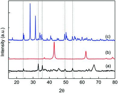 | ||
| Fig. 1 XRD diffraction patterns of (a) Rh–Fe/Ca–Al2O3, (b) Rh–Fe/MgO and (c) Rh–Fe/ZrO2. Dotted lines correspond to the diffraction peaks of α-Fe2O3. | ||
H2 chemisorption experiments were conducted to measure the active Rh surface area. As shown in Table 1, the Rh metal particle sizes, calculated based on the surface areas, are consistent with the particle sizes obtained from TEM (Fig. 2) only for unpromoted Rh supported catalysts. In the presence of iron oxide, a significant decrease in the H2 adsorption capacity (more than 60% on Rh–Fe/ZrO2, 34% for Rh–Fe/MgO and 8.2% for Rh–Fe/Ca–Al2O3) is observed and the extent depends on the support. In general, the metallic surface area reflects the metal dispersion/particle size where a higher metallic surface area indicates the smaller metallic particles. However, the changes in particle sizes on Rh–Fe catalysts are very marginal as shown in TEM (Fig. 2). Therefore, the decreased adsorption capacity of H2 on Rh–Fe catalysts could not be ascribed to the sintering of Rh particles.
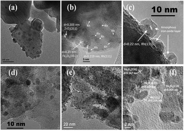 | ||
| Fig. 2 TEM micrographs of reduced (a) Rh/ZrO2, (b) Rh–Fe/ZrO2 and (c) Rh–Fe/ZrO2 (in high resolution), (d) Rh/Ca–Al2O3, (e) Rh–Fe/Ca–Al2O3 and (f) Rh–Fe/Ca–Al2O3 (in high resolution). TEM micrograph of (f) is reproduced for comparison.6 | ||
Suppression of H2/CO chemisorption on noble metals supported on reducible oxides (i.e. Fe2O3, V2O5, TiO2 and Nb2O5) after high temperature reduction is well documented in literature.8,18 This effect, where partially reduced metal oxide covers the noble metal particle after high temperature reduction, is due to strong metal support interaction (SMSI).12,19 A 60% decrease in H2 chemisorption on reduced Rh–Fe/ZrO2, would result in Rh particle sizes of around 24 nm based on the H2 adsorption capacity. However, most of the Rh particles are less than 5 nm, as shown in Fig. 2b. A Similar phenomenon was observed by Naumann d'Alnoncourt et al. on Pd/Fe2O3.8 The HR-TEM (Fig. 2c) clearly shows that Rh particle has an amorphous overlayer of iron oxide on reduced Rh–Fe/ZrO2, which is an evidence of SMSI between Rh and iron oxide. Furthermore, the elemental analysis by EDX in dark field mode image (Fig. S1, ESI†) also indicates the coexistence of Rh, Fe and Zr in a 3 nm diameter. In addition, both decrease of ca. 41% in the Rh/Fe atomic ratio derived from XPS (Table 1) and the presence of lower oxidation state of Fe (see XPS of Fe 2p in Fig. S2 in ESI† and in situ XRD in Fig. 5) after in situ reduction of Rh–Fe/ZrO2 once again verify the encapsulation of Rh particles by partially reduced iron oxide in its SMSI state.
Unlike ZrO2 supported catalysts, there is only 8.2% decrease in the metallic surface area in Rh–Fe/Ca–Al2O3 compared to Rh/Ca–Al2O3. The Rh particles of Rh–Fe/Ca–Al2O3 still remain at around 2.5 nm and is consistent with TEM observation (Fig. 2e). Atomic ratio of Rh/Fe of Rh–Fe/Ca–Al2O3 is increased by 4%, which falls within the margin of error (Table 1). Thus, it can be concluded that the extent of SMSI is very weak between Rh and Fe2O3 when they are supported on Ca–Al2O3. As a matter of fact, high resolution TEM of reduced Rh–Fe/Ca–Al2O3 previously shown in the ESI of ref. 6 (and reproduced here in Fig. 2f for sake of clarity) has clearly indicated that there is no encapsulation of Rh by iron oxide. The decrease in H2 adsorption capacity is probably due to the interaction between Rh and iron oxide at their interfaces. Such CUF interfacial sites are also observed by Fu et al. on FeO1−x/Pt(111) surfaces, where a linear correlation between the surface reactivity with the density of the FeO island edge sites clearly indicates that CUF sites are the active ones in CO oxidation.9
The dispersion of Rh/MgO is only 36%, being smaller than that of Rh/Ca–Al2O3 despite having comparable BET surface areas. It is most probably due to strong interaction between Rh and MgO as reported by Ruckenstein et al.,20 resulting in poor reducibility. There is a ca. 34% decrease in Rh metallic surface area in the presence of iron oxide (Table 1). However, the atomic ratio of Rh/Fe calculated from XPS shows no significant difference before and after reduction, which indicates the small extent of SMSI effect on Rh–Fe/MgO as well. The more significant decrease in metal surface area on Rh–Fe/MgO as compared to Rh–Fe/Ca–Al2O3, may be attributed to the increase in particle size in the presence of iron oxide on MgO. Tanaka et al. reported an increase from 5.6 nm to 15.7 nm when ca. 1 wt% of Fe was added to 1 wt% Rh/MgO.21 Unfortunately, clear images of the particle size of Rh/MgO and Rh–Fe/MgO from TEM could not be successfully obtained. Since there is obvious evidence of SMSI on Rh–Fe/MgO from XPS data, it is most likely that Rh and iron oxide are present as Rh–FexOy as in the case of Rh–Fe/Ca–Al2O3.
CO is a good probe molecule of both catalyst surface structure and adsorption sites using FTIR. Although, CO adsorption on Rh-based catalysts has been well studied,22–24 there are few studies on iron oxide promoted Rh catalyst supported on metal oxides.25Fig. 3 shows the DRIFTS spectra of chemisorbed CO on reduced Rh and Rh–Fe catalysts. Two strong adsorption bands at 2019 and 2092 cm−1, assigned to symmetric and asymmetric carbonyl stretching of the dicarbonyl Rh+(CO)2 complex, respectively, are observed on Rh/Ca-Al2O3. In addition, linear CO on Rh0 are observed at 2056 cm−1.26 On Rh/MgO, gem dicarbonyl, linear and bridge bonded CO on Rh0 species are observed. However, they are easily removed at room temperature by flushing with He. On Rh/ZrO2, only the linear and bridge bonded CO on Rh0 features at 2056 and 1856 cm−1 are identified. It is generally accepted that the detection of gem-dicarbonyl CO species is an indication of the existence of highly dispersed Rh metal particles on the catalyst surface. Bianchi et al. reported only the existence of gem-dicarbonyl CO species at 2090 and 2021 cm−1 on a reduced 0.6% Rh/Al2O3 sample, while linear (2065 cm−1) and bridged (1861 cm−1) CO species were predominantly found on a 3% Rh/Al2O3 sample, having presumably larger Rh particles.26 Therefore, these results indicate a decreasing metal dispersion in the order of Rh/Ca–Al2O3, Rh/MgO and Rh/ZrO2 which is consistent with our hydrogen chemisorption data.
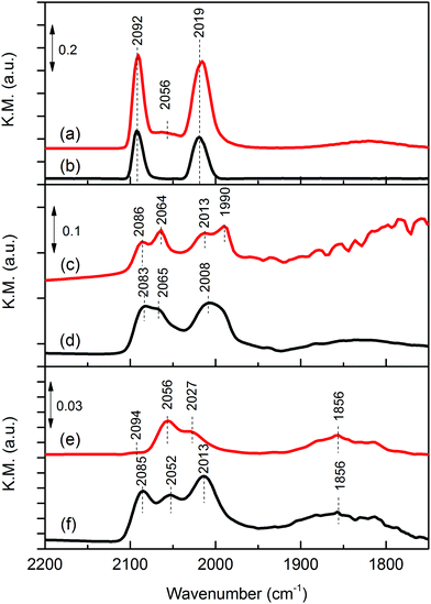 | ||
| Fig. 3 In situ DRIFTS of adsorbed CO over reduced catalysts: (a) Rh/Ca–Al2O3; (b) Rh–Fe/Ca–Al2O3; (c) Rh/MgO; (d) Rh–Fe/MgO; (e) Rh/ZrO2 and (f) Rh–Fe/ZrO2. | ||
In the presence of iron oxide, only gem-dicarbonyl species are observed on Rh–Fe/Ca–Al2O3. On Rh–Fe/MgO and Rh–Fe/ZrO2, the intensities of linear-bonded CO bands at 2065 and 2056 cm−1 attenuate and the intensities of the twin bands of the dicarbonyl become higher than those of linear-bonded CO. Similar observation was found by Haider et al. with a smaller Fe loading.25 Therefore, in summary, H2 chemisorption, in situ DRIFT of CO adsorption and TEM results have shown that the presence of iron oxides depresses the concentration of Rh0 on the surface of Rh–Fe catalysts. This is also reflected from the Rh 3d XPS spectra of reduced Rh–Fe catalysts presented in ESI† (Fig. S3). The extent of influence, however, varies with the catalyst support. SMSI between Rh and iron oxide occurs on ZrO2 support while on Ca–Al2O3 and MgO, the SMSI between Rh and Fe2O3 is relatively weak, and the interaction of Rh and Fe2O3 is probably only confine on the interface.9 The main reason is related to the reducibility of the iron oxide which will be elaborated later.
3.2. Iron and support effect on the catalytic performance of Rh catalysts
The catalytic performance of supported Rh and Rh–Fe catalysts in low temperature ESR at 623 K is compared in Table 2. The major detected products are CO2, CH4, CO, C2H4 and C2H4O, indicating the occurrence of several side reactions such as ethanol decomposition, dehydration, dehydrogenation, decarbonylation and water−gas shift reaction (eqn (R2)–(R6)).| Catalyst | X EtOH (%) | Y H2 (mol H2/mol EtOH) | Selectivity of carbon-containing species (%) | ||||
|---|---|---|---|---|---|---|---|
| S CO2 | S CO | S CH4 | S C2H4 | S CH3CHO | |||
| Rh/Ca–Al2O3 | 93.4 | 3.6 | 16.7 | 47.0 | 36.4 | 0.0 | 0.0 |
| Rh–Fe/Ca–Al2O3 | 100.0 | 4.1 | 60.3 | 0.0 | 39.7 | 0.0 | 0.0 |
| Rh/MgO | 89.4 | 2.9 | 17.7 | 35.9 | 41.4 | 0.7 | 4.2 |
| Rh–Fe/MgO | 100.0 | 4.0 | 53.4 | 4.1 | 42.5 | 0.0 | 0.0 |
| Rh/ZrO2 | 100.0 | 4.3 | 55.2 | 9.3 | 35.5 | 0.0 | 0.0 |
| Rh–Fe/ZrO2 | 99.1 | 4.2 | 47.2 | 17.2 | 32.8 | 0.0 | 2.8 |
High selectivity to CO is observed on Rh/MgO and Rh/Ca–Al2O3 catalysts due to the strong C–C bond breaking ability of Rh, suggesting that ethanol decomposition (eqn (R2)) and acetaldehyde decarbonylation (eqn (R5)) reactions are dominant. The high selectivity toward CO on Rh and other noble metal catalysts was often reported.4,5 However, the presence of iron oxides can greatly suppress the selectivity of CO over these two catalysts. The CO selectivity is reduced from 47% to 0% on Rh–Fe/Ca–Al2O3 and from 35.9% to 4.1% on Rh–Fe/MgO. In contrast, the selectivity toward CO increases from 9.3% to 17.2% on iron promoted Rh/ZrO2 catalyst, suggesting a difference in the nature of the active sites on Rh–Fe/ZrO2. This hypothesis is reinforced by the Arrhenius plot shown in Fig. 4. The apparent activation energy, Ea, which can be derived from the slopes of the Arrhenius plots are quite similar over Rh–Fe/Ca–Al2O3 and Rh–Fe/MgO with values of 49.2 kJ mol−1 and 52.2 kJ mol−1, respectively. However, a larger Ea (57.0 kJ mol−1) is obtained on Rh–Fe/ZrO2.
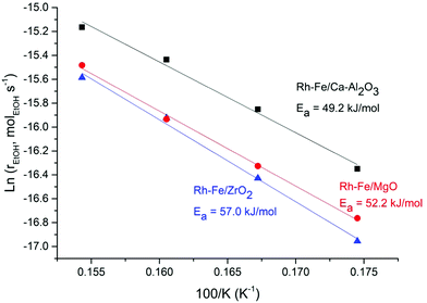 | ||
Fig. 4 Arrhenius plot for ethanol steam reforming on Rh–Fe/Ca–Al2O3 (▲), Rh–Fe/MgO ( ) and Rh–Fe/ZrO2 ( ) and Rh–Fe/ZrO2 ( ) catalysts. ) catalysts. | ||
It was previously proven that the promotional effect of iron on Rh–Fe/Ca–Al2O3 occurs in the presence of coordinatively unsaturated ferrous sites at the Rh–FexOy interface.6,7 Since the behavior of Rh–Fe/MgO is similar to Rh–Fe/Ca–Al2O3, it is reasonable to propose that same active sites are present on Rh–Fe/MgO. Meanwhile, catalytic results and Ea have indicated that active sites of Rh–Fe/ZrO2 are different, which emphasizes the importance of the catalyst support. In the next section, various techniques will be applied to unravel how the catalyst support affects the interaction between Rh–iron–support.
3.3. Rh–iron oxide–support interactions
The interaction between Rh and iron are affected by the nature of the supports, i.e. ZrO2, Ca–Al2O3 and MgO. It is well known that the interaction between an oxide and the support affects the reduction process of the supported oxide. Therefore, in situ XRD and XAS under reducing conditions were carried out to elucidate the effect of support on this interaction.Fig. 5a shows the evolution of XRD patterns during temperature-programmed reduction of Rh–Fe/ZrO2. Clear bulk reduction of the iron oxide from Fe2O3 (initial) → Fe3O4 (473 K) → Fe (673 K) can be observed on Rh–Fe/ZrO2. Rietveld refinement fittings indicate that the phase composition of Rh–Fe/ZrO2 consists mainly of ZrO2 (88%) and Fe3O4 (12%) at 523 K. Metallic Fe(011) phase starts to appear at 625 K. For Rh–Fe/MgO (Fig. 5b), the diffraction peaks observed at its initial state are indexed to MgO. In situ XRD carried out under H2 shifts the MgO(002) diffraction peak at 42.9° toward a lower angle, becoming broader as the temperature increases to 550 K. This could be associated to the formation of solid solution (FeO)x(MgO)1−x as MgFe2O4 is being reduced.27 High reduction temperature (>773 K) is required to reduce Fe oxide species to metallic Fe on the Rh–Fe/MgO sample. As for Rh–Fe/Ca–Al2O3 catalyst, XRD patterns in Fig. 5c are characterized by high structured background and very poor signal to noise ratio. Weak diffraction peaks of Al2O3 and α-Fe2O3 are poorly resolved at 303 K. The reduction of Fe2O3 to Fe3O4 is vaguely visible at 573 K. Metallic Fe can be observed at 723 K. The Rietveld refinement analysis of Rh–Fe/Ca–Al2O3 is very difficult at the reduction temperature of 523 K due to the complexity of these XRD patterns. Nevertheless, it is reasonable to conclude that the extent of interaction between iron oxide and the different supports increases in the order of ZrO2, Ca–Al2O3 and MgO based on the temperature at which metallic Fe appears. TPR profiles monitored using TCD also show similar trend (see Fig. S4, ESI†).
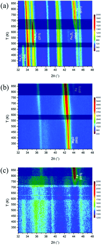 | ||
| Fig. 5 Evolution of XRD patterns of Rh–Fe catalysts during reduction: (a) Rh–Fe/ZrO2; (b) Rh–Fe/MgO and (c) Rh–Fe/Ca–Al2O3. | ||
While XRD is limited by the crystallinity of the samples, XAFS can be applied for both amorphous and crystalline samples. The reducibility of iron oxides on Rh–Fe catalysts can be observed from the shift in the edge position of XANES as shown in Fig. 6. In well agreement with the in situ XRD results, XANES evolution show that the reducibility of iron oxide is decreasing in the following order: Rh–Fe/ZrO2 > Rh–Fe/Ca–Al2O3 > Rh–Fe/MgO.
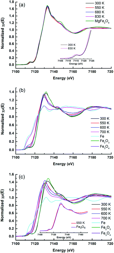 | ||
| Fig. 6 Evolution of Fe K-edge XANES spectra under flowing H2 at various temperatures: (a) Rh–Fe/MgO, (b) Rh–Fe/ZrO2 and (c) Rh–Fe/Ca–Al2O3. | ||
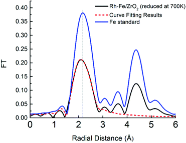
The facile reduction of iron oxide on ZrO2 may induce the formation of surface RhFe alloy. The formation of RhFe alloy on Rh–Fe/ZrO2 is possible due to the high reducibility of iron oxide and the similarity of the lattice structure between Rh and Fe.28 A detailed EXAFS analysis was conducted to determine the structure of the reduced Fe clusters for the Rh–Fe/ZrO2 sample. Fourier transformed of Fe K edge of Rh–Fe/ZrO2 reduced at 700 K in Fig. 7 shows a contraction in Fe–Fe radial distance from 2.17 (in Fe metal foil) to 2.11 Å in the presence of Rh, suggesting the possible formation of a Rh–Fe alloy. The structural parameters from the EXAFS data (see ESI,† Table S1), obtained through a fitting procedure, indicate the existence of a small fraction of Rh in close interaction with Fe and suggests the formation of RhFe alloy in its SMSI state on ZrO2 support.
For Rh–Fe/Ca–Al2O3, the absorption edge of the reduced catalyst closely resembles to Fe3O4 standard. Nevertheless some distinct differences between the XANES spectrum of reduced Rh–Fe/Ca–Al2O3 at 550 K and that of Fe3O4 standard (inset of Fig. 6b) are noted. Therefore, it can be concluded that the iron oxide on Rh–Fe/Ca–Al2O3 sample reduced at 550 K consists of a complex mixture of partially reduced iron oxide where the valence state of iron is closer to that of Fe3O4.
The key benefit of XAFS is the ability of revealing amorphous or minority phases that cannot detected by the in situ XRD measurements. For example, the pre-edge and the main edge features of the as-calcined Rh–Fe/MgO resembles to those of MgFe2O4 standard (Fig. 6a). This is further substantiated by the Fourier transform (FT) of the k3-weighted Fe K-edge extended X-Ray absorption fine structure (EXAFS) of Rh–Fe/MgO displayed in Fig. 8, which shows the main features of MgFe2O4. Such spinel structure is not revealed by XRD, probably because the low calcination temperature leads to amorphous MgFe2O4. Therefore, the strong interaction between iron oxide and MgO is well proven.
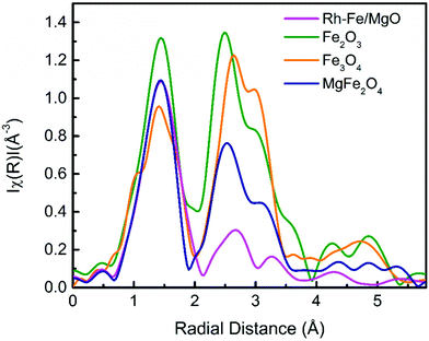 | ||
| Fig. 8 Fourier transformation of the k3-weighted EXAFS function at the Fe K-edge of as-calcined Rh–Fe/MgO, along with reference compounds, Fe2O3, Fe3O4 and MgFe2O4. | ||
3.4. Correlation of catalytic performance with the Rh–iron oxide–support interaction
The reducibility of the oxide is an important measurement of the extent of the SMSI, which occurs on metals supported on reducible oxides, where the reducible oxides migrate onto the surface of its supported metals.8 From the characterization results, we identify that the metal–support interaction exists among the three entities, i.e. Rh ↔ Fe2O3 ← support (ZrO2, MgO and Ca–Al2O3). Characterization by in situ XRD and XAS under reduction conditions in flowing hydrogen has shown that the reduction extent of iron oxide decreases in the following order: ZrO2 > Ca–Al2O3 > MgO. Consequently, the exposed metallic Rh surface area (measured by H2-chemisorption, Table 1) decreased upon the addition of iron oxide and the percentage of the decrease correlates well with the iron oxide reducibility on different support previously discussed. Hence, the SMSI between Rh and iron oxide on Rh–Fe/ZrO2 is a consequence of the lack of interaction between Fe2O3 and ZrO2. After reduction, RhFe alloy may be formed. Contrarily, moderate to strong Fe2O3 interaction with Ca–Al2O3 and MgO regulate the extent of the reduction of iron oxide, and thus greatly reduces the extent of SMSI between Rh and iron oxide on Rh–Fe/Ca–Al2O3 and Rh–Fe/MgO. The structures of the reduced catalysts are proposed and illustrated in Scheme 1. | ||
| Scheme 1 Schematic illustrations of the structure of (a) Rh–Fe/Ca–Al2O3; (b) Rh–Fe/MgO and (c) Rh–Fe/ZrO2 after reduction in H2 at 550 K. | ||
Although the catalysts were reduced at 473 K prior to ethanol steam reforming at 623 K, in situ XRD and XAFS experiments under diluted H2 covered the range from room temperature to 873 K (XRD) and 800 K (XAFS). These in situ results indicate that there is no significant observable changes from 473 K (reduction temperature) to 623 K (reforming temperature). Therefore, the investigation under reduction condition in Scheme 1 is a well representation of the initial state of catalysts under ESR condition. However, reaction-induced modification of the catalyst surfaces may occur on some catalysts. For example, further reduction of bimetallic Rh0.5Pd0.5/CeO2 catalyst was found under ESR at 823 K as the reaction produces H2 and the catalyst was initially reduced at 573 K only.30
Thus, it has been proven that the interface between Rh and the partially reduced iron oxide species FexOy are responsible for the efficient removal of CO during ESR. The ethanol C–C bond is cleaved by Rh and the resulting CO is spilled over to FexOy where it is further converted to CO2via WGSR.6,7 The moderate interaction between iron oxide and Ca–Al2O3 stabilizes the FexOy species to prevent SMSI between Rh and FexOy, resulting in a very stable CO-free ESR catalyst, exhibiting a stable catalytic activity for 288 h at 623 K.6 Similar reactive pair of Ni0–Ce3+ has recently been proven by high pressure XPS under ESR conditions by Liu et al.29
Although the conversion of ethanol has been increased and the selectivity to CO also decreased on Rh–Fe/MgO, the catalytic performance of Rh–Fe/MgO is less effective as compared to Rh–Fe/Ca–Al2O3. This may suggest that less FexOy sites in the vicinity of Rh are available for CO conversion due to the strong interaction between iron oxide and MgO. Indeed, as revealed in XAS and XRD, iron oxide species remain largely as MgFe2O4. Therefore, less Rh–FexOy sites are available. It is obvious that the weak interaction between iron oxide and ZrO2 induces the SMSI between Rh and iron oxide, possible forming a RhFe alloy after initial reduction. This may change the electronic properties of Rh, being not beneficial for the removal of CO from the reaction product due to the lack of Rh–FexOy sites. However, the possibility of changing the initial metallic state after reduction during the ESR cannot be ruled out.8,30,31 This will require in situ investigation under ESR reaction conditions.
4. Conclusions
The results from the current study clearly show that iron promotion completely removes the undesired CO by-product on Rh–/Ca–Al2O3 (47.0% vs. 0.0%) while a less effective promotion effect is observed on Rh/MgO (35.9% vs. 4.1%). Contrarily, iron oxide addition increases the CO selectivity on Rh/ZrO2 (9.3% vs. 17.2%). A thorough in situ characterization of the promoted catalysts indicates that the interaction between the support and iron oxide plays a crucial role in determining the chemical states of Rh and iron oxides, thereby affecting the chemical nature and the availability of the active sites Rh–FexOy present on the catalyst surface for ESR.The intimate interaction between Rh and iron oxide leads to the formation of Rh–FexOy active sites on Rh–Fe/Ca–Al2O3 and Rh–Fe/MgO. An adverse effect on the catalytic performance is observed on Rh–Fe/ZrO2 as a result of the SMSI effect between Rh and iron oxides due to the weak interaction between ZrO2 and iron oxide. The strong Fe2O3 and MgO interaction favors the formation of MgFe2O4, reducing the availability of partially reducible Fe2O3 on the surface and generating less Rh–FexOy active sites. Therefore, a moderate interaction between iron oxide and Ca–Al2O3 is the key to maximize the number of Rh–FexOy active sites and stabilize these sites, making the Rh–Fe/Ca–Al2O3 catalyst a unique catalyst for CO-free ethanol steam reforming at low temperature.
This study demonstrates the feasibility in manipulating the reducibility of reducible oxides via proper selection of the support. As such, the interaction between noble metals and the reducible oxides can be shifted from the encapsulation of noble metals by the reducible oxide to the confinement of partially reduced oxide at the interfaces between the noble metal and the reducible oxide.
Acknowledgements
We gratefully acknowledge the financial support from the Science and Engineering Research Council (SERC) of the Agency for Science, Technology and Research (A*STAR), Singapore. We thank the assistance of Dr Ming Lin for dark field images and elemental analysis in TEM and Ms Zhan Wang for XPS measurements.References
- J. Llorca, P. R. de la Piscina, J. A. Dalmon, J. Sales and N. Homs, Appl. Catal., B, 2003, 43, 355–369 CrossRef CAS.
- J. Sun, D. Luo, P. Xiao, L. Jigang and S. Yu, J. Power Sources, 2008, 184, 385–391 CrossRef CAS.
- C. Zhang, P. Zhang, S. Li, G. Wu, X. Ma and J. Gong, Phys. Chem. Chem. Phys., 2012, 14, 3295–3298 RSC.
- H. S. Roh, Y. Wang, D. King, A. Platon and Y. H. Chin, Catal. Lett., 2006, 108, 15–19 CrossRef CAS.
- M. A. Goula, S. K. Kontou and P. E. Tsiakaras, Appl. Catal., B, 2004, 49, 135–144 CrossRef CAS.
- L. Chen, C. K. S. Choong, Z. Zhong, L. Huang, T. P. Ang, L. Hong and J. Lin, J. Catal., 2010, 276, 197–200 CrossRef CAS.
- C. S. Choong, L. Chen, Y. Du, Z. Wang, L. Hong and A. Borgna, Top. Catal., 2014, 57, 627–636 CrossRef CAS.
- R. Naumann d’Alnoncourt, M. Friedrich, E. Kunkes, D. Rosenthal, F. Girgsdies, B. Zhang, L. Shao, M. Schuster, M. Behrens and R. Schlögl, J. Catal., 2014, 317, 220–228 CrossRef.
- Q. Fu, W. X. Li, Y. Yao, H. Liu, H.-Y. Su, D. Ma, X. K. Gu, L. Chen, Z. Wang, H. Zhang, B. Wang and X. Bao, Science, 2010, 328, 1141–1144 CrossRef CAS PubMed.
- L. Liu, F. Zhou, L. Wang, X. Qi, F. Shi and Y. Deng, J. Catal., 2010, 274, 1–10 CrossRef CAS.
- M. Lewandowski, Y. N. Sun, Z. H. Qin, S. Shaikhutdinov and H. J. Freund, Appl. Catal., A, 2011, 391, 407–410 CrossRef CAS.
- A. D. Logan, E. J. Braunschweig, A. K. Datye and D. J. Smith, Langmuir, 1988, 4, 827–830 CrossRef CAS.
- S. Labich, E. Taglauer and H. Knözinger, Top. Catal., 2000, 14, 153–161 CrossRef CAS.
- K. Hayek, B. Jenewein, B. Klötzer and W. Reichl, Top. Catal., 2000, 14, 25–33 CrossRef CAS.
- C. K. S. Choong, L. Huang, Z. Zhong, J. Lin, L. Hong and L. Chen, Appl. Catal., A, 2011, 407, 155–162 CrossRef CAS.
- Y. Du, Y. Zhu, S. Xi, P. Yang, H. O. Moser, M. B. H. Breese and A. Borgna, J. Synchrotron Radiat., 2015, 22, 839–843 CrossRef CAS PubMed.
- C. K. S. Choong, Z. Zhong, L. Huang, Z. Wang, T. P. Ang, A. Borgna, J. Lin, L. Hong and L. Chen, Appl. Catal., A, 2011, 407, 145–154 CrossRef CAS.
- S. J. Tauster and S. C. Fung, J. Catal., 1978, 55, 29–35 CrossRef CAS.
- G. L. Haller and D. E. Resasco, in Advances in Catalysis, ed. H. P. D. D. Eley and B. W. Paul, Academic Press, 1989, vol. 36, pp. 173–235 Search PubMed.
- E. Ruckenstein and H. Y. Wang, J. Catal., 2000, 190, 32–38 CrossRef CAS.
- H. Tanaka, R. Kaino, K. Okumura, T. Kizuka, Y. Nakagawa and K. Tomishige, Appl. Catal., A, 2010, 378, 175–186 CrossRef CAS.
- F. Solymosi and M. Pasztor, J. Phys. Chem., 1985, 89, 4789–4793 CrossRef CAS.
- S. Trautmann and M. Baerns, J. Catal., 1994, 150, 335–344 CrossRef CAS.
- J. T. Yates, T. M. Duncan, S. D. Worley and R. W. Vaughan, J. Chem. Phys., 1979, 70, 1219–1224 CrossRef CAS.
- M. A. Haider, M. R. Gogate and R. J. Davis, J. Catal., 2009, 261, 9–16 CrossRef CAS.
- O. Dulaurent, K. Chandes, C. Bouly and D. Bianchi, J. Catal., 2000, 192, 262–272 CrossRef CAS.
- D. E. Stobbe, F. R. van Buren, A. W. Stobbe-Kreemers, A. J. van Dillen and J. W. Geus, J. Chem. Soc., Faraday Trans., 1991, 87, 1631–1637 RSC.
- K. Hanisch, W. Keune, R. A. Brand, C. Binek and W. Kleemann, J. Appl. Phys., 1994, 76, 6528–6530 CrossRef CAS.
- Z. Liu, T. Duchon, H. Wang, D. C. Grinter, I. Waluyo, J. Zhou, Q. Liu, B. Jeong, E. J. Crumlin, V. Matolin, D. J. Stacchiola, J. A. Rodriguez and S. D. Senanayake, Phys. Chem. Chem. Phys., 2016, 18, 16621–16628 RSC.
- N. J. Divins and J. Llorca, Appl. Catal., A, 2016, 518, 60–66 CrossRef CAS.
- N. J. Divins, I. Angurell, C. Escudero, V. Pérez-Dieste and J. Llorca, Science, 2014, 346, 620–623 CrossRef CAS PubMed.
Footnote |
| † Electronic supplementary information (ESI) available. See DOI: 10.1039/c6cp05934a |
| This journal is © the Owner Societies 2017 |

