 Open Access Article
Creative Commons Attribution 3.0 Unported Licence
Growth mechanism and electrochemical properties of hierarchical hollow SnO2 microspheres with a “chestnut” morphology†
Huating
Hu
a,
Liming
Wu
bc,
Paul
Gebhardt
ae,
Xiaofei
Zhang
a,
Alexey
Cherevan
ae,
Birgit
Gerke
f,
Rainer
Pöttgen
f,
Andrea
Balducci
abcd,
Stefano
Passerini
 bc and
Dominik
Eder
 *ae
*ae
aInstitute of Physical Chemistry, University of Münster, Corrensstraße 28/30, 48149 Münster, Germany
bHelmholtz Institute Ulm, Helmholtzstraße 11, 89081 Ulm, Germany
cKarlsruher Institute of Technology (KIT), PO Box 3640, 76021 Karlsruhe, Germany
dInstitute for Technical Chemistry and Environmental Chemistry Center for Energy and Environmental Chemistry Jena (CEEC Jena), Philosophenweg 7A, 07743 Jena, Germany
eInstitut für Materialchemie, Technische Universität Wien, Getreidemarkt 9, 1060 Wien, Austria. E-mail: dominik.eder@tuwien.ac.at; Tel: +49 251 83 23406
fInstitut für Anorganische und Analytische Chemie, Universität Münster, Corrensstrasse 30, D-48149 Münster, Germany
First published on 4th September 2017
Abstract
Hierarchical hollow microspheres (HHMSs) constitute a very popular class of materials for use as drug-delivery carriers, photocatalysts and electrode materials in batteries, owing to their large, porous surface area and mechanical integrity during intercalation reactions. Here, we used a template- and additive-free hydrothermal route to prepare an unusually shaped SnO2 material that comprises a hollow spherical morphology with uniform diameters and very thin petal-like nano-sheets grown perpendicularly on the sphere's surface, resembling a “chestnut cupule”. We thoroughly investigated the formation mechanism by 119Sn Mössbauer spectroscopy, powder X-ray diffraction and X-ray photoelectron spectroscopy. Key to this process is the ultrasonic pre-treatment of an aqueous SnCl2 solution, followed by Ostwald “inside-out” ripening upon hydrothermal processing. This unique morphology has greatly improved the storage capacity and cycling performance of SnO2 as an anode material for lithium and sodium ion batteries compared with conventional SnO2 materials.
1. Introduction
As documented recently by two comprehensive review articles,1,2 hierarchical hollow microspheres (HHMSs) have evolved as an attractive class of materials for many applications, where a large and easily-accessible surface area, high pore volume and good mechanical and thermal stability are required. For example, HHMSs have been frequently investigated as nano-reactors and drug-delivery carriers, in electromagnetic wave absorption,3,4 as well as in photocatalysis5 and as active compounds in gas sensors6 and in photovoltaic devices.7–9 In recent years, the focus on HHMSs has shifted to their use as anode materials in lithium ion batteries (LIBs) and, recently, sodium-ion batteries (SIBs).10–15Graphite, the conventional anode materials in LIBs, is limited by its rather low theoretical specific capacity (e.g. 372 mA h g−1) and, in particular, volumetric capacities.16 Its use in SIBs is even more hampered, as Na ions are too large to be inserted into the graphite interlayers.12 Therefore, much research has been devoted to anodes of metal oxides, such as TiO2, Fe3O4, and SnO2.10,17–19 SnO2 has evolved as one of the most promising candidates, due to its intrinsically high theoretical specific capacity (782 mA h g−1 and 667 mA h g−1 for LIBs7 and SIBs17 respectively), environmental benignity and low cost.7,12,20,21 However, conventional SnO2 materials suffer from a severe volume change (i.e. more than 200%) when SnO2 becomes reduced and reacts with Li to form Li4.4Sn during the charge and discharge process, typically leading to pulverization of the electrode and thus a rapid capacity decay.22 This effect is even more pronounced for Na+ intercalation, due to its larger ion radius than Li+ (by about 55%).10 Nanostructured materials, such as nanosheets,23 nanoboxes,24 nanotubes,20 and, particularly, hollow spheres,25–31 have been demonstrated to cope with volume expansions during Li+/Na+ insertion and extraction significantly better than their respective bulk counterparts.25–31
Hollow micro/nanostructures are generally synthesized via wet-chemical methods that involve hard or soft templates and often require time-consuming multi-step processes (i.e. annealing, template removal, etc.).32–35 For example, Wang et al. have synthesized SnO2 HHMSs through a fluoride-mediated process,36 while Gurunathan et al. have used the resorcinol–formaldehyde (RF) gel method.37 Both studies demonstrate improved electrochemical stability for LIB application. There are also examples for template-free synthesis of HHMSs for metal oxides, such as TiO2,38 Cu2O,39 SnO2 (ref. 3 and 31) and NiO.40 They often involve organic solvents, acids and additives, which increase cost, have greater negative environmental impact and are generally not desirable for large-scale fabrication. While there are many recent works on the synthesis and application of such hollow structures, only a few studies have so far reported their formation mechanism, nucleation and growth, in particular regarding template- and additive-free processes.
In this work we synthesized hollow SnO2 microspheres via a template-free route without any additives/solvents, by utilizing an ultrasonication-assisted hydrothermal process. The resulting material consists of hollow spheres, which uniquely exhibits vertically grown nano-sized petal structures that resemble the cupules of chestnuts. We investigated the growth mechanism in detail, using X-ray powder diffraction (XRD), X-ray photoelectron spectroscopy (XPS) and 119Sn Mössbauer spectroscopy. We developed a growth model that is applicable to a wide range of inorganic compounds and provides new insight regarding the formation of hollow microsphere materials. Finally, we tested the electrochemical performance of SnO2 microspheres in lithium-ion batteries and, for the first time, in sodium-ion batteries.
2. Experimental
Materials synthesis
In a typical reaction a certain amount (0.1–1.0 g) of tin(II)chloride dihydrate (SnCl2·2H2O, 98%, Sigma-Aldrich) was dissolved in 35 ml deionized (DI) water and treated in an ultrasonic (US) bath (Bandelin Sonorex Digitec, 35 kHz) for 5–120 min. Subsequently, the solution was transferred into a Teflon-lined autoclave and heated at 120 °C for 6 h. Then the product was immersed in a large amount of DI water and altered for 1–2 hours before being filtered, washed with DI water and dried at 60 °C overnight. For comparison, the reaction solution was hydrothermally processed without ultrasonic pre-treatment and the effects of reaction temperature and sonication time were investigated.Characterisation
The materials were characterised by scanning electron microscopy (SEM; Zeiss XB 1540 EsB, 2 kV) and transmission electron microscopy (TEM; Zeiss Libra 200) using a 200 kV acceleration voltage. The samples were further analysed by powder X-ray diffraction (XRD), using a Bruker, D8 Advance with Cu-Kα radiation (λ = 1.5406 Å), and by nitrogen physisorption (BET/BJH), using a Micromeritics ASAP 2010. The chemical composition of the samples was obtained by X-ray photoelectron spectroscopy (XPS) using a VG ESCALAB 250 with Al-Kα radiation. A Ca119mSnO3 source was used for the 119Sn Mössbauer spectroscopic experiments. The measurements were carried out at ambient temperature in a transmission geometry. The Mössbauer source was kept at room temperature. The samples were enclosed in small PMMA containers. Palladium foil of 0.05 mm thickness was used to reduce tin K-X-rays concurrently emitted by this source. Fitting of the spectra was performed with the Normos-90 program system.41Electrochemical measurements
Electrodes were prepared by dissolving sodium carboxymethyl cellulose (CMC, WALOCEL™ CRT 2000 PPA 12, Dow Wolff Cellulosics) in DI water to form a 1.25 wt% solution followed by addition of SnO2 HHMSs and conductive carbon (SuperC65®, TIMCAL), aiming for an overall electrode composition of 70![[thin space (1/6-em)]](https://www.rsc.org/images/entities/char_2009.gif) :
:![[thin space (1/6-em)]](https://www.rsc.org/images/entities/char_2009.gif) 20
20![[thin space (1/6-em)]](https://www.rsc.org/images/entities/char_2009.gif) :
:![[thin space (1/6-em)]](https://www.rsc.org/images/entities/char_2009.gif) 10 (w/w/w, SnO2
10 (w/w/w, SnO2![[thin space (1/6-em)]](https://www.rsc.org/images/entities/char_2009.gif) :
:![[thin space (1/6-em)]](https://www.rsc.org/images/entities/char_2009.gif) SuperC65®
SuperC65®![[thin space (1/6-em)]](https://www.rsc.org/images/entities/char_2009.gif) :
:![[thin space (1/6-em)]](https://www.rsc.org/images/entities/char_2009.gif) CMC). The resulting mixture was dispersed by ball milling for 3 h. The obtained slurry was then casted onto copper foil (Schlenk) using a laboratory doctor blade. After drying at room temperature, disk electrodes (∅ = 12 mm) were punched and dried under vacuum at 120 °C for 12 h. The active material loading on the electrode was ∼1.7 mg cm−2. Three-electrode Swagelok cells with lithium (Rockwood Lithium, battery grade) and sodium (Alfa Aesar, battery grade) metal foils as counter and reference electrodes were assembled in an Ar-filled glove box (MBraun) with the oxygen and moisture contents kept below 0.5 ppm. The electrolyte was prepared using a solution of 1.0 M LiPF6 or NaClO4 in ethylene carbonate (EC) and diethyl carbonate (DEC) (w/w = 1
CMC). The resulting mixture was dispersed by ball milling for 3 h. The obtained slurry was then casted onto copper foil (Schlenk) using a laboratory doctor blade. After drying at room temperature, disk electrodes (∅ = 12 mm) were punched and dried under vacuum at 120 °C for 12 h. The active material loading on the electrode was ∼1.7 mg cm−2. Three-electrode Swagelok cells with lithium (Rockwood Lithium, battery grade) and sodium (Alfa Aesar, battery grade) metal foils as counter and reference electrodes were assembled in an Ar-filled glove box (MBraun) with the oxygen and moisture contents kept below 0.5 ppm. The electrolyte was prepared using a solution of 1.0 M LiPF6 or NaClO4 in ethylene carbonate (EC) and diethyl carbonate (DEC) (w/w = 1![[thin space (1/6-em)]](https://www.rsc.org/images/entities/char_2009.gif) :
:![[thin space (1/6-em)]](https://www.rsc.org/images/entities/char_2009.gif) 1). A Whatman™ glass fibre disc was used as a separator in all cells. Cyclic voltammetry (CV) was carried out between 2.0 and 0.02 V at a scan rate of 0.5 mV s−1 using a VMP3 potentiostat (BIOLOGIC). The charge/discharge measurements at room temperature were performed in a voltage window of 0.02–2.0 V at different current densities using a Maccor Battery Tester 4300. The current density is expressed in C-rate, where 1C corresponds to an applied specific current of 782 mA g−1 and 667 mA g−1 for Li+ and Na+ cells, respectively. All potential values refer to the Li/Li+ or Na/Na+ reference couples.
1). A Whatman™ glass fibre disc was used as a separator in all cells. Cyclic voltammetry (CV) was carried out between 2.0 and 0.02 V at a scan rate of 0.5 mV s−1 using a VMP3 potentiostat (BIOLOGIC). The charge/discharge measurements at room temperature were performed in a voltage window of 0.02–2.0 V at different current densities using a Maccor Battery Tester 4300. The current density is expressed in C-rate, where 1C corresponds to an applied specific current of 782 mA g−1 and 667 mA g−1 for Li+ and Na+ cells, respectively. All potential values refer to the Li/Li+ or Na/Na+ reference couples.
3. Results and discussion
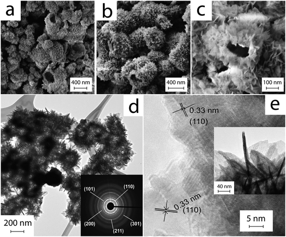
Fig. 1 shows typical SEM and TEM images of a sample after ultrasonication for 5 min and hydrothermal processing at 120 °C for 6 h. The images reveal a hollow spherical morphology with diameters ranging from 300 to 400 nm; the shells are thin and surprisingly uniform in thickness (∼50 nm). In contrast to previously reported HHMSs, these spheres resemble the form of “chestnut cupules”, i.e. thin shells that are partly open and decorated with free-standing petals. The petals are 4–5 nm in thickness, approximately 30 nm in width and up to 80 nm in length. The SAED pattern in the inset of Fig. 1d shows fine diffraction spots that can be assigned to (110), (101), (200) and (211) of SnO2 with a rutile-type structure. The HRTEM image in Fig. 1e further reveals that the petals consist of extended crystalline domains; the petals appear to have grown perpendicularly to the sphere's surface, as indicated by the (110) fringes pointing towards the surface. Importantly, a reference experiment without ultrasonic pre-treatment did not yield this unique morphology, but rather produced large aggregates of particles and nanoplates (Fig. S1†).Fig. 2a shows the XPS spectra of the as-produced material including all characteristic peaks of Sn (i.e. 3p, 3d, 4s, 4p, 4d) and a single peak at 532.8 eV that can be attributed to O1s of SnO2. Importantly, the presence of two peaks between 480 and 500 nm, i.e. Sn 3d5/2 (487.8 eV) and Sn 3d3/2 (496.3 eV), and their separation in binding energy by 8.5 eV due to spin–orbital coupling of Sn 3d are characteristic of phase-pure SnO2.42 Nitrogen physisorption yielded a surface area of 65 m2 g−1 according to the Brunauer–Emmett–Teller (BET) method (Fig. 2b), which is considerably larger than those of particulate SnO2 (4.2 m2 g−1) and ordered porous SnO2 (7.8 m2 g−1).43 Furthermore, it shows a type IV isotherm with a type H3 hysteresis loop at relative pressures P/Po of 0.4–1.0, which is indicative of the presence of a spherical mesoporous morphology. Fig. 2b shows the BJH pore size distribution with a peak maximum at about 4 nm, presumably corresponding to the average distance between the individual petals on the surface of the spheres, which is in line with TEM observations (Fig. 1).
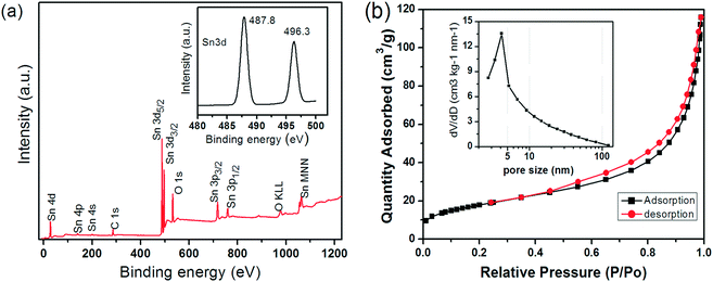 | ||
| Fig. 2 (a) XPS spectrum of the SnO2 HHMSs and the corresponding Sn 3d doublet (inset); (b) nitrogen adsorption/desorption isotherms and the corresponding BJH distributions (inset) of the SnO2 HHMSs. | ||
In order to understand the growth mechanism of the SnO2 HHMSs, we varied the ultrasonication and hydrothermal processing times as well as the hydrothermal reaction temperature and analysed the samples by powder XRD and 119Sn Mössbauer spectroscopy.
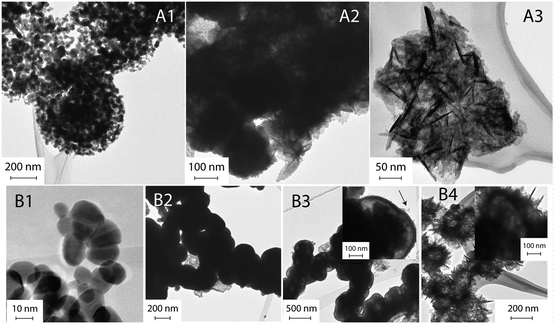
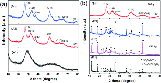
We first investigated the samples that were not ultrasonicated before being hydrothermally processed at 120 °C for various periods (route A). The TEM image of the sample after 30 min of autoclaving (Fig. 3-A1) shows small nanoparticles with diameters of 30–40 nm that are loosely assembled into large, sometimes spherical agglomerates with surprisingly uniform diameters of about 500 nm. XRD indicates that these nanoparticles are amorphous (Fig. 4-A1). With prolonged autoclaving time, the nanoparticles within the agglomerates accumulated into dense, spherical aggregates (2 h, Fig. 3-A2) and finally merged to create nanoplates (6 h, Fig. 3-A3). The XRD pattern in Fig. 4a confirms that both samples are predominantly crystalline with (110), (101), (200), (211), (310), (301), and (321) reflections corresponding to SnO2 with a rutile-type structure (JCPDS 41-1445).
Secondly, we investigated the sample that was first ultrasonicated for 5 min and subsequently autoclaved at 120 °C for various periods (route B). It is important to note that ultrasonic treatment alone has already yielded white precipitates (Fig. S2a†). These consist of predominantly crystalline nanoparticles with diameters in the range of 15–20 nm (Fig. 3-B1). XRD reveals the presence of Sn2+ compounds (Fig. 4b-B1), which can be indexed to Sn6O4(OH)4 (ref. 44) and Sn3O(OH)2Cl2.45 After a short period of autoclaving (30 min), the size of these particles increased to about 300 nm (Fig. 3-B2) without significantly altering their phase composition and color (Fig. 4b-B2 and S2b†). Upon further extending the processing time, the particles were converted into partly hollow spheres with distinctive shells (Fig. 3-B3) and the as-obtained product now appears to be light yellow (Fig. S2c†). This step is accompanied by the evolution of new diffraction peaks assignable to rutile-type SnO2 (Fig. 4b-B3). However, the rather broad peaks indicate that the shells are either amorphous or consist of very small crystallites. Interestingly, some spheres already contain some platelets on their surface (Fig. 3-B3). The final product appeared after 6 h as deep yellow precipitates (Fig. S2d†) and contains hierarchical SnO2 hollow microspheres with the aforementioned “chestnut cupule” morphology (Fig. 3-B4). The spheres are crystalline and consist entirely of rutile-type SnO2 with no visible residues of other phases (Fig. 4b-B4).
The samples were further analysed by 119Sn Mössbauer spectroscopy; the results are summarized in Fig. 5 along with transmission integral fits and the corresponding fitting parameters are listed in Table 1. All spectra show a superposition of a Sn(IV) and a Sn(II) signal, however with distinctly different ratios. While there is an almost equal partition of both tin oxidation states in the sample after 30 min of autoclaving (a), only a tiny amount of divalent tin is observed in the 119Sn spectrum of the final product (d). The Sn(IV) signals derive from the distorted SnO6 octahedra of the hollow SnO2 microspheres. Slightly asymmetric electron densities around the elongated octahedra result in small quadrupole splitting parameters. The divalent tin species can be assigned to Sn6O4(OH)4![[thin space (1/6-em)]](https://www.rsc.org/images/entities/char_2009.gif) 44 and Sn3O(OH)2Cl2,45 in line with the XRD results and supported by the second 119Sn signals in the range of 3.01–3.22 mm s−1 observed for (a)–(d). Due to the pronounced lone-pair character of Sn(II), these signals show much higher quadrupole splitting than the Sn(IV) ones. The isomer shift and quadrupole splitting values determined for our samples are in good agreement with those reported for pure Sn3O(OH)2Cl2 (δ = 3.35 mm s−1 and ΔEQ = 1.85 mm s−1).46 The ratio of the Sn(IV) to Sn(II) signal continuously turns towards almost exclusively Sn(IV) from sample (a) to sample (d). Again, this is in line with the XRD patterns (Fig. 4b-B4), which shows only nanocrystalline SnO2 for the final product.
44 and Sn3O(OH)2Cl2,45 in line with the XRD results and supported by the second 119Sn signals in the range of 3.01–3.22 mm s−1 observed for (a)–(d). Due to the pronounced lone-pair character of Sn(II), these signals show much higher quadrupole splitting than the Sn(IV) ones. The isomer shift and quadrupole splitting values determined for our samples are in good agreement with those reported for pure Sn3O(OH)2Cl2 (δ = 3.35 mm s−1 and ΔEQ = 1.85 mm s−1).46 The ratio of the Sn(IV) to Sn(II) signal continuously turns towards almost exclusively Sn(IV) from sample (a) to sample (d). Again, this is in line with the XRD patterns (Fig. 4b-B4), which shows only nanocrystalline SnO2 for the final product.
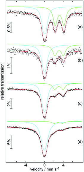 | ||
| Fig. 5 Experimental (data points) and simulated (continuous lines) 119Sn Mössbauer spectra of samples (a) B1, (b) B2, (c) B3 and (d) B4 at ambient temperature. | ||
| Compound | δ (mm s−1) | ΔEQ (mm s−1) | Γ (mm s−1) | Ratio (%) |
|---|---|---|---|---|
| (a) | 0.03(1) | 0.54(1) | 1.01(2) | 49(1) |
| 3.22(2) | 1.85(1) | 1.05(2) | 51(1) | |
| (b) | 0.00(1) | 0.47(4) | 1.19(5) | 62(1) |
| 3.13(1) | 1.80(3) | 1.12(3) | 38(1) | |
| (c) | 0.00(1) | 0.52(1) | 1.10(1) | 74(1) |
| 3.09(1) | 1.78(2) | 1.14(3) | 26(1) | |
| (d) | −0.02(1) | 0.54* | 1.43(1) | 91(1) |
| 2.93(2) | 1.74(2) | 1.25(6) | 9(1) |
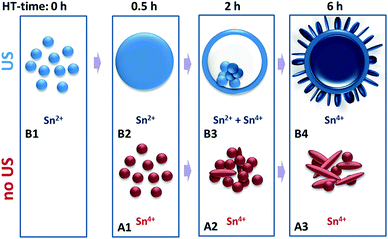
The growth of these HHMSs presumably follows a multi-step mechanism as suggested in Fig. 6. In a first step, aided by the ultrasonic (US) process, SnCl2 hydrolyses and partially oxidizes to crystalline Sn2+-species that precipitate as nanoparticles. The second step involves autoclaving, upon which these nanoparticles grow in size, either via 1) dissolution of smaller nanoparticles and recrystallization on the surface of larger particles (conventional Ostwald ripening) or 2) continuous attachment of residual Sn2+ ions from the reaction solution onto the surface of existing nanoparticles. In order to distinguish between these two scenarios we performed two experiments: firstly, we replaced the precursor solution (after US treatment) with pure DI water before autoclaving, in which case we did not observe any significant particle growth into hollow spheres during hydrothermal processing, even at elevated reaction temperatures (Fig. S3†). Secondly, we increased the initial precursor concentration from 0.05 g l−1 to 0.11 g l−1 and now observed an increase in the average diameter (Fig. S4†). Hence, the growth requires a continuous supply of Sn2+ ions from the reaction solution, whose initial concentration defines the final size of the spheres.
The transformation from dense particles into hollow spheres constitutes the third step. It presumably follows an “inside-out” Ostwald ripening mechanism, upon which the Sn2+-species from the interior of the particles oxidize to Sn4+ species and create a solid shell of SnO2, driven by pressure/concentration gradients with respect to the outer solution.31 This is associated with a slight growth in size and clearly documented in the TEM images in Fig. 3-B3.
Eventually, residual materials from the interior of the sphere diffuse through the shell, nucleate on the outer surface and then grow perpendicularly to the surface in the form of crystalline nanoplatelets. This is in line with the preferred growth orientation parallel to the (110) planes as seen by HRTEM (Fig. 3-B4). Remember, the conventional hydrothermal method without ultrasonic pretreatment only yielded agglomerates of particles and large platelets. These are formed directly from solution through immediate oxidation of SnCl2 without solid precipitation of Sn2+ species and thus without inducing “inside-out” Ostwald ripening (Fig. 3-A3). Therefore, it appears that the combination of ultrasonic pretreatment and hydrothermal processing facilitates the successful formation of the “chestnut” structures.
We also evaluated the potential of SnO2 HHMSs as anode materials for LIBs and SIBs. The electrochemical characteristics were measured by cyclic voltammetry (CV) and galvanostatic charge/discharge tests between 0.02–3.0 V vs. Li/Li+ or Na/Na+, using the corresponding metals (i.e. Li or Na) as cathodes. Fig. 7a shows the CV profiles of the LIBs for the first, second and fifth cycles at a scanning rate of 0.5 mV s−1. The first cycle reveals an irreversible reduction peak centered at 1.0 V. According to previous studies, such a broad peak might originate from the reduction of SnO2 to metallic tin (see eqn (1))47 and the simultaneous decomposition of electrolytes leading to the formation of the solid electrolyte interphase (SEI) (see eqn (2)).48 The 2nd cycle reveals two rather broad peaks between 0.1–0.6 V, which can be assigned to the formation of LixSn phases, as depicted in eqn (3). The presence of two anodic peaks, corresponding to de-alloying, suggests that this process is highly reversible and mainly responsible for the reversible lithium storage capacity of the Sn based materials. However, it is important to point out that the persistence of the cathodic peak above 1.0 V vs. Li/Li+ may indicate an additional contribution by the partial recovery of tin oxide (i.e. reversibility of reaction 1). This phenomenon has been observed in several transition metal oxides, including tin oxides.12,49–51
| SnO2 + 4Li+ + 4e−1 → Sn + 2Li2O | (1) |
| Li+ + e− + electrolyte → SEI (Li) | (2) |
| Sn + xLi+ + xe−1 ↔ LixSn (0 ≤ x ≤ 4.4) | (3) |
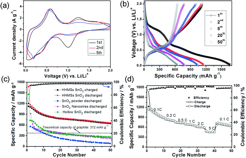 | ||
| Fig. 7 Lithium insertion in SnO2 HHMSs. (a) 1st, 2nd and 5th cyclic voltammograms at a scanning rate of 0.5 mV s−1; (b) galvanostatic charge and discharge profiles (1st, 10th, 20th, 40th and 50th cycles) at 0.1C; (c) prolonged cycling test of SnO2 HHMSs at 0.1C. The results are compared with those of the hollow SnO2 spheres,36 SnO2 nanowires, and SnO2 powder;15 (d) rate performance at different current rates. All potential values here refer to the Li/Li+ reference couple. All measurements were performed at 20 ± 2 °C. | ||
Fig. 7b displays the charge/discharge voltage profiles of SnO2 HHMSs at 0.1C for the 1st, 2nd, 5th, 20th and 50th cycles. In the first cycle, two poorly defined plateaus can be identified from the discharge curve. The first plateau at ∼1.0 V again corresponds to the reduction of SnO2 to metallic tin and the simultaneous SEI formation (in line with the CV data), while the voltage region between 0.1–0.6 V is attributed to the multi-step reactions involving Li–Sn phases (eqn (3)). In this latter voltage area, Li+ ions insert continuously into the intermetallic phase and many structural phase transitions may occur between Sn, Li2Sn5, LiSn, Li7Sn3, Li5Sn2, Li3Sn5, Li7Sn2, and Li4.4Sn,52 which is in agreement with Fig. 6. The partly irreversible conversion of SnO2 to metallic tin is typically cited as the origin of the commonly low coulombic efficiency (Qdelith/Qlith is ca. 70%), as further indicated by the rather different delithiation and lithiation capacities of 1123 mA h g−1 and 1667 mA h g−1, respectively. In the subsequent cycles, however, the coulombic efficiency increases substantially (i.e. to about 95%), presumably due to a sharp decrease of the lithiation capacity (1167 mA h g−1), while the effective lithium storage remains almost constant (1107 mA h g−1). After the 8th cycle the coulombic efficiency is highly stable and remains above 97–98%.
Although the capacity has decreased slightly (mainly occurring during the initial five cycles), which is common for SnO2 based electrode materials,15,36,53 the HHMSs still retain a remarkably high capacity of 659 mA h g−1, even after 50 cycles (Fig. 7c). This value is in fact 1.8 times higher than the theoretical capacity of graphite.15,36,53 It is also considerably higher than those of other SnO2 nanostructures, such as previous hollow spheres (280 mA h g−1) and, most importantly, of a solid SnO2 nanoparticle reference (45 mA h g−1), as summarized in Fig. 7c.
The SnO2 HHMS-based electrodes also exhibit excellent rate performance. As shown in Fig. 7d, they deliver a reversible discharge capacity of 730 mA h g−1 at 1C and retain a high capacity of 463 mA h g−1 even at a high rate of 5C. This may be explained by the faster charge transport properties within the highly crystalline SnO2 nanopetals. After reducing the discharge rate to 0.1C, the electrode again delivers a high capacity of 651 mA h g−1, which shows that the electrode has not suffered from any losses in performance. Importantly, the stability and overall rate capability at high capacities of our SnO2 HHMS are even better than those of the best SnO2@C yolk–shell nanospheres.53
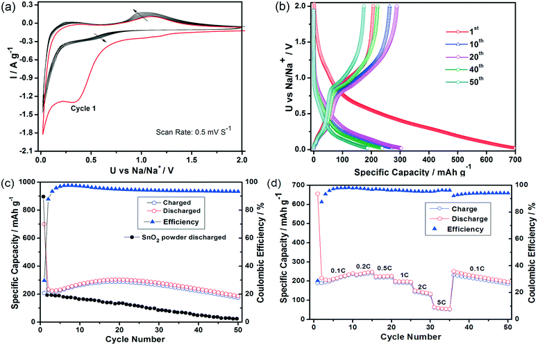
Fig. 8 illustrates that the SnO2 HHMS materials also show a highly promising sodium storage performance as documented by the initial ten cycles performed at a scanning rate of 0.5 mV s−1 (Fig. 8a). The peaks seen in the 1st cycle correspond to the largely irreversible reduction of the metal oxide to Sn0 and the formation of NaxSn phases embedded into the Na2O matrix, yet they appear at much lower potentials compared to those of previous reports.17 Furthermore, the CV curves show no apparent changes between the 2nd to the 10th cycles, which documents an excellent reversibility during the formation of the intermetallic phase. Again, although the irreversible capacity in the first cycle is somewhat high, as expected, i.e. comparing a Qsodiation of 700 mA h g−1versus a Qdesodiation of 224 mA h g−1, the sodium storage capacity is retained at high levels and surprisingly even increases slightly with progressing number of cycles before decreasing again to 304 mA h g−1 after the 20th cycle.
The SnO2 HHMS electrodes also show favorable capacity retention ability as documented by the very high levels of 186 mA h g−1 even after 50 cycles, which corresponds to 83% of the initial capacity (i.e. 2nd cycle) (Fig. 8c). Besides, from the 7th cycle onwards, the coulombic efficiency remains very high, i.e. above 94%. The SnO2 HHMSs also show an improved rate performance in SIBs compared to commercial SnO2 powder,12,15 with highly stable average capacities of 236 mA h g−1 and 190 mA h g−1 at rates of 0.2C and 1C, respectively (Fig. 8d), and with retrieval of the initial capacity upon decreasing the rate back to 0.1C.
A closer look at the electrode after 50 cycles (Fig. S5†) revealed that the SnO2 HHMSs are still very well dispersed within the electrode matrix and their morphology is seemingly unaffected. Future studies with a high cycle number will provide further information on the long-term stability of these materials; yet, these first results demonstrate that our SnO2 HHMSs yield a considerably enhanced and more stable electrochemical performance in both, Li- and Na-ion batteries, owing to their unusual structure that offers a high surface area, fast charge transport within the crystalline petals and an overall improved mechanical stability.
4. Conclusions
We have synthesized highly porous SnO2 HHMSs with enhanced electrochemical properties using a template- and additive-free route. With the help of 119Sn Mössbauer spectroscopy, powder XRD and XPS we were able to unravel the underlying formation process. This process involves a crucial ultrasonic pre-treatment of aqueous SnCl2 solution, followed by Ostwald “inside-out” ripening upon hydrothermal processing. The resulting SnO2 materials resemble a “chestnut cupule” structure involving hollow spheres of uniform thickness and very thin petal-like nanosheets grown perpendicularly on the sphere's surface. These structures exhibited a considerably higher storage capacity and cycling performance as anode materials for lithium and sodium ion batteries compared with conventional SnO2 materials. In particular, we observed reversible capacities of 659 mA h g−1 and 186 mA h g−1 with a corresponding coulombic efficiency as high as 98% and 94% for lithium and sodium, respectively, that remained stable up to at least 50 cycles. The capacities are twice as large as those of previous hollow SnO2 materials and several times larger than those of dense nanoparticles. The improved electrochemical performance is clearly associated with the unique “chestnut” morphology of the SnO2 HHMSs, which provides fast charge transport within the crystalline petals and an overall improved mechanical stability. The 3D hierarchical interconnected structure and additional presence of crystalline nanosheets provide a large accessible surface area with open channels that facilitates Li+/Na+ ion diffusion from the electrolyte and so enhances the amount of ion intercalation. In addition, the high porosity of these HHMSs allows for better coping with the large volume changes during cycling and thus prevents the pulverization of the SnO2 electrodes.Note added in proof
We apologize for having unintentionally overlooked and not referenced a recent publication that is relevant to this paper and covers a significant part of our research (see ref. 54). Our paper confirms these previous results and extends the studies on the mechanism of HHMS formation with additional XPS and Mössbauer spectroscopy. Our paper further corroborates the electrochemical data regarding lithium-ion batteries, yet it extends the investigations to sodium-ion batteries.Conflicts of interest
There are no conflicts to declare.References
- X. Wang, et al., Synthesis, Properties, and Applications of Hollow Micro-/Nanostructures, Chem. Rev., 2016, 116(18), 10983–11060 CrossRef CAS PubMed.
- G. Prieto, et al., Hollow Nano- and Microstructures as Catalysts, Chem. Rev., 2016, 116(22), 14056–14119 CrossRef CAS PubMed.
- B. Zhao, et al., Yolk–Shell Ni@SnO2 Composites with a Designable Interspace To Improve the Electromagnetic Wave Absorption Properties, ACS Appl. Mater. Interfaces, 2016, 8(42), 28917–28925 CAS.
- B. Zhao, et al., Corrosive synthesis and enhanced electromagnetic absorption properties of hollow porous Ni/SnO2 hybrids, Dalton Trans., 2015, 44(36), 15984–15993 RSC.
- L. Shi and H. Lin, Facile Fabrication and Optical Property of Hollow SnO2 Spheres and Their Application in Water Treatment, Langmuir, 2010, 26(24), 18718–18722 CrossRef CAS PubMed.
- A. Rao, et al., In Situ Localized Growth of Ordered Metal Oxide Hollow Sphere Array on Microheater Platform for Sensitive, Ultra-Fast Gas Sensing, ACS Appl. Mater. Interfaces, 2017, 9(3), 2634–2641 CAS.
- H. Wang and A. L. Rogach, Hierarchical SnO2 Nanostructures: Recent Advances in Design, Synthesis, and Applications, Chem. Mater., 2013, 26(1), 123–133 CrossRef.
- S. Ding, et al., Formation of SnO2 Hollow Nanospheres inside Mesoporous Silica Nanoreactors, J. Am. Chem. Soc., 2010, 133(1), 21–23 CrossRef PubMed.
- W. W. Wang, Y. J. Zhu and L. X. Yang, ZnO–SnO2 Hollow Spheres and Hierarchical Nanosheets: Hydrothermal Preparation, Formation Mechanism, and Photocatalytic Properties, Adv. Funct. Mater., 2007, 17(1), 59–64 CrossRef CAS.
- C. Luo, et al., Selenium@Mesoporous Carbon Composite with Superior Lithium and Sodium Storage Capacity, ACS Nano, 2013, 7(9), 8003–8010 CrossRef CAS PubMed.
- S.-W. Kim, et al., Electrode Materials for Rechargeable Sodium-Ion Batteries: Potential Alternatives to Current Lithium-Ion Batteries, Adv. Energy Mater., 2012, 2(7), 710–721 CrossRef CAS.
- Y. Wang, et al., SnO2@MWCNT nanocomposite as a high capacity anode material for sodium-ion batteries, Electrochem. Commun., 2013, 29(0), 8–11 CrossRef CAS.
- H. Wang, et al., Renewable-Juglone-Based High-Performance Sodium-Ion Batteries, Adv. Mater., 2015, 27(14), 2348–2354 CrossRef CAS PubMed.
- D. Kundu, et al., The Emerging Chemistry of Sodium Ion Batteries for Electrochemical Energy Storage, Angew. Chem., Int. Ed., 2015, 54(11), 3431–3448 CrossRef CAS PubMed.
- M.-S. Park, et al., Preparation and Electrochemical Properties of SnO2 Nanowires for Application in Lithium-Ion Batteries, Angew. Chem., 2007, 119(5), 764–767 CrossRef.
- H. B. Wu, et al., Synthesis of SnO2 Hierarchical Structures Assembled from Nanosheets and Their Lithium Storage Properties, J. Phys. Chem. C, 2011, 115(50), 24605–24610 CAS.
- D. Su, et al., Octahedral tin dioxide nanocrystals as high capacity anode materials for Na-ion batteries, Phys. Chem. Chem. Phys., 2013, 15(30), 12543–12550 RSC.
- N. Yabuuchi, et al., Research Development on Sodium-Ion Batteries, Chem. Rev., 2014, 114(23), 11636–11682 CrossRef CAS PubMed.
- L. Wu, et al., Anatase TiO2 nanoparticles for high power sodium-ion anodes, J. Power Sources, 2014, 251(0), 379–385 CrossRef CAS.
- J. Ye, et al., Morphology-Controlled Synthesis of SnO2 Nanotubes by Using 1D Silica Mesostructures as Sacrificial Templates and Their Applications in Lithium-Ion Batteries, Small, 2010, 6(2), 296–306 CrossRef CAS PubMed.
- L. Wu, et al., Unfolding the Mechanism of Sodium Insertion in Anatase TiO2 Nanoparticles, Adv. Energy Mater., 2015, 5(2), 1401142–1401153 CrossRef.
- X. W. Lou, et al., Preparation of SnO2/Carbon Composite Hollow Spheres and Their Lithium Storage Properties, Chem. Mater., 2008, 20(20), 6562–6566 CrossRef CAS.
- C. Wang, et al., Large-Scale Synthesis of SnO2 Nanosheets with High Lithium Storage Capacity, J. Am. Chem. Soc., 2009, 132(1), 46–47 CrossRef PubMed.
- Z. Wang, et al., Fast Formation of SnO2 Nanoboxes with Enhanced Lithium Storage Capability, J. Am. Chem. Soc., 2011, 133(13), 4738–4741 CrossRef CAS PubMed.
- J. Ning, et al., Facile Synthesis of Tin Oxide Nanoflowers: A Potential High-Capacity Lithium-Ion-Storage Material, Langmuir, 2008, 25(3), 1818–1821 CrossRef PubMed.
- R. Demir-Cakan, et al., Facile One-Pot Synthesis of Mesoporous SnO2 Microspheres via Nanoparticles Assembly and Lithium Storage Properties, Chem. Mater., 2008, 20(4), 1227–1229 CrossRef CAS.
- S. Jing, et al., Lithium storage improvement from hierarchical double-shelled SnO2 hollow spheres, RSC Adv., 2014, 4(21), 10450–10453 RSC.
- S. Ding and X. Wen Lou, SnO2 nanosheet hollow spheres with improved lithium storage capabilities, Nanoscale, 2011, 3(9), 3586–3588 RSC.
- H. X. Yang, et al., Multilayered Nanocrystalline SnO2 Hollow Microspheres Synthesized by Chemically Induced Self-Assembly in the Hydrothermal Environment, J. Phys. Chem. C, 2007, 111(38), 14067–14071 CAS.
- D. Deng and J. Y. Lee, Hollow Core–Shell Mesospheres of Crystalline SnO2 Nanoparticle Aggregates for High Capacity Li+ Ion Storage, Chem. Mater., 2008, 20(5), 1841–1846 CrossRef CAS.
- X. W. Lou, et al., Template-Free Synthesis of SnO2 Hollow Nanostructures with High Lithium Storage Capacity, Adv. Mater., 2006, 18(17), 2325–2329 CrossRef CAS.
- Q. Zhao, et al., Oxidation−Crystallization Process of Colloids: An Effective Approach for the Morphology Controllable Synthesis of SnO2 Hollow Spheres and Rod Bundles, J. Phys. Chem. C, 2007, 111(31), 11598–11603 CAS.
- S. Han, et al., Simple Synthesis of Hollow Tin Dioxide Microspheres and Their Application to Lithium-Ion Battery Anodes, Adv. Funct. Mater., 2005, 15(11), 1845–1850 CrossRef CAS.
- X. Sun, J. Liu and Y. Li, Use of Carbonaceous Polysaccharide Microspheres as Templates for Fabricating Metal Oxide Hollow Spheres, Chem. – Eur. J., 2006, 12(7), 2039–2047 CrossRef CAS PubMed.
- Y. Wang, et al., Crystalline Carbon Hollow Spheres, Crystalline Carbon−SnO2 Hollow Spheres, and Crystalline SnO2 Hollow Spheres: Synthesis and Performance in Reversible Li-Ion Storage, Chem. Mater., 2006, 18(5), 1347–1353 CrossRef CAS.
- H. Wang, et al., Hydrothermal synthesis of hierarchical SnO2 microspheres for gas sensing and lithium-ion batteries applications: Fluoride-mediated formation of solid and hollow structures, J. Mater. Chem., 2012, 22(5), 2140–2148 RSC.
- P. Gurunathan, P. M. Ette and K. Ramesha, Synthesis of Hierarchically Porous SnO2 Microspheres and Performance Evaluation as Li-Ion Battery Anode by Using Different Binders, ACS Appl. Mater. Interfaces, 2014, 6(19), 16556–16564 CAS.
- J. G. Yu, Y. R. Su and B. Cheng, Template-Free Fabrication and Enhanced Photocatalytic Activity of Hierarchical Macro-/Mesoporous Titania, Adv. Funct. Mater., 2007, 17(12), 1984–1990 CrossRef CAS.
- H. Zhang, et al., One-Pot Synthesis and Hierarchical Assembly of Hollow Cu2O Microspheres with Nanocrystals-Composed Porous Multishell and Their Gas-Sensing Properties, Adv. Funct. Mater., 2007, 17(15), 2766–2771 CrossRef CAS.
- C.-Y. Cao, et al., Microwave-assisted gas/liquid interfacial synthesis of flowerlike NiO hollow nanosphere precursors and their application as supercapacitor electrodes, J. Mater. Chem., 2011, 21(9), 3204–3209 RSC.
- R. A. Brand, NORMOS Mössbauer fitting Program, Universität Duisburg, Duisburg (Germany), 2007 Search PubMed.
- F. Li, et al., One-step synthesis of graphene/SnO2 nanocomposites and its application in electrochemical supercapacitors, Nanotechnology, 2009, 20(45), 455602 CrossRef PubMed.
- Y. N. Ko, S. B. Park and Y. C. Kang, Design and Fabrication of New Nanostructured SnO2-Carbon Composite Microspheres for Fast and Stable Lithium Storage Performance, Small, 2014, 10(16), 3240–3245 CrossRef CAS PubMed.
- I. Abrahams, S. M. Grimes, S. R. Johnston and J. C. Knowles, Tin(II) Oxyhydroxide by X-ray Powder Diffraction, Acta Crystallogr., Sect. C: Cryst. Struct. Commun., 1996, 52, 285–288 Search PubMed.
- J. J. Matzko, et al., Abhurite, a new tin hydroxychloride mineral, and a comparative study with a synthetic basic tin chloride, Can. Mineral., 1985, 23(2), 233–240 CAS.
- S. Ichiba and M. Takeshita, Mössbauer study of tin(II) chloride hydroxide and tin(II) hydroxide oxide, Bull. Chem. Soc. Jpn., 1984, 57, 1087–1091 CrossRef CAS.
- N. Pereira, L. C. Klein and G. G. Amatucci, Particle size and multiphase effects on cycling stability using tin-based materials, Solid State Ionics, 2004, 167(1–2), 29–40 CrossRef CAS.
- E. Peled, The Electrochemical Behavior of Alkali and Alkaline Earth Metals in Nonaqueous Battery Systems—The Solid Electrolyte Interphase Model, J. Electrochem. Soc., 1979, 126(12), 2047–2051 CrossRef CAS.
- J. Chen and K. Yano, Highly Monodispersed Tin Oxide/Mesoporous Starbust Carbon Composite as High-Performance Li-Ion Battery Anode, ACS Appl. Mater. Interfaces, 2013, 5(16), 7682–7687 CAS.
- J. Lin, et al., Graphene Nanoribbon and Nanostructured SnO2 Composite Anodes for Lithium Ion Batteries, ACS Nano, 2013, 7(7), 6001–6006 CrossRef CAS PubMed.
- M. Gu, et al., Probing the Failure Mechanism of SnO2 Nanowires for Sodium-Ion Batteries, Nano Lett., 2013, 13(11), 5203–5211 CrossRef CAS PubMed.
- W.-M. Zhang, et al., Tin-Nanoparticles Encapsulated in Elastic Hollow Carbon Spheres for High-Performance Anode Material in Lithium-Ion Batteries, Adv. Mater., 2008, 20(6), 1160–1165 CrossRef CAS.
- J. Wang, et al., Controllable synthesis of SnO2@C yolk-shell nanospheres as a high-performance anode material for lithium ion batteries, Nanoscale, 2014, 6(6), 3217–3222 RSC.
- X. M. Yin, et al., One-Step Synthesis of Hierarchical SnO2 Hollow Nanostructures via Self-Assembly for High Power Lithium Ion Batteries, J. Phys. Chem. C, 2010, 114(17), 8084–8088 CAS.
Footnote |
| † Electronic supplementary information (ESI) available. See DOI: 10.1039/c7ce01288h |
| This journal is © The Royal Society of Chemistry 2017 |

