
 Open Access Article
 This Open Access Article is licensed under a
 Creative Commons Attribution 3.0 Unported Licence
Syntheses, structural diversity, magnetic properties and dye absorption of various Co(II) MOFs based on a semi-flexible 4-(3,5-dicarboxylatobenzyloxy)benzoic acid†
Xiang-min
Meng
ac,
Lian-sheng
Cui
d,
Xin-ping
Wang
a,
Xiao-yin
Zhang
c,
Xia
Zhang
c and
Shuang-yu
Bi
 *b
*b
aCollege of Marine Science and Biological Engineering, Qingdao University of Science and Technology, Qingdao, Shandong 266042, P.R. China
bMax Planck Institute for Terrestrial Microbiology & LOEWE Center for Synthetic Microbiology (SYNMIKRO), Marburg, Germany. E-mail: shuangyu.bi@synmikro.mpi-marburg.mpg.de
cKey Laboratory of Marine Chemistry Theory and Technology, Ministry of Education, College of Chemistry and Chemical Engineering, Ocean University of China, Qingdao, Shandong 266100, P.R. China
dCollege of Chemistry and Environmental Engineering, Baise University, Baise, Guangxi 533000, P.R. China
First published on 4th October 2017
Abstract
Five novel Co(II) metal–organic frameworks (MOFs) constructed from semi-flexible 4-(3,5-dicarboxylatobenzyloxy)benzoic acid (H3L), namely {[Co1.5(HL)(4,4′-bidpe)2(H2O)]·3H2O}n (1), {[Co3(L)2(4,4′-bibp)3(μ2-O)2]·2H2O}n (2), {[Co(HL)(1,3-bitl)]·(1,4-Diox)}n (3), [Co2(HL)2(3,5-bipd)2]n (4), and {[Co(HL)(tib)]·0.5H2O·NMP}n (5) (4,4′-bidpe = 4,4′-bis(imidazolyl)diphenyl ether, 4,4′-bibp = 4,4′-bis(imidazol-1-yl)biphenyl, 1,3-bitl = 1,3-bis(1-imidazoly)toluene, 3,5-bipd = 3,5-bis(1-imidazoly)pyridine, and tib = 1,3,5-tris(1-imidazolyl)benzene), were synthesized under solvothermal conditions and further characterized by elemental analysis, IR spectra, powder X-ray diffraction (PXRD), thermogravimetric (TG) analysis and single-crystal X-ray diffraction. Different architectural topologies have been generated by adjusting the N-donor ligands. Single-crystal X-ray diffraction analysis reveals that complex 1 shows a rare 1D → 2D polyrotaxane network. Complex 2 possesses an unprecedented 2-nodal (3,10)-connected 3D framework with a Schläfli symbol of (43)2(46·632·83)(43)2. When the 2-connected points (H3L and 1,3-bitl ligands) are not calculated, complex 3 shows a hcb uninodal 3-connected 2D network with the Schläfli symbol (63), which further constructs a 3D supramolecular structure through O–H⋯O hydrogen bonds; while the 2-connected points are taken into account, complex 3 exhibits an unprecedented 3-nodal (2,2,4)-connected network. Complex 4 presents an unprecedented 2-nodal (3,5)-connected 3D framework with a (4·62)(4·66·83) topology, while complex 5 exhibits another unprecedented 2-nodal (3,5)-connected 2D framework with a (42·67·8)(42·6) Schläfli symbol and shows 2D → 3D supramolecular structure through O–H⋯O hydrogen bonds. Meanwhile, the magnetic properties of complexes 2 and 4 are discussed. Moreover, the dye adsorption and mechanism studies indicate that the pore size, the uncoordinated O atoms in carboxyl groups and the uncoordinated carboxyl groups of the MOFs have significant effects on the dye adsorption capacity.
Introduction
In recent years, the construction and research of metal–organic frameworks (MOFs) have attracted significant research attention in materials science due to their diverse topological structures1–3 and their promising applications in luminescence,4–6 magnetism,7,8 gas storage,9,10 ion exchange,11 molecular sensing and separation,12 catalysis,13,14 dye adsorption15,16 and so on.17 Particularly, the removal of organic dyes (e.g. methylene blue, rhodamine B, acriflavine hydrochloride, Congo red, brilliant green and methyl orange) from wastewater is becoming a significant application for MOFs depending on the pore shape, and this aspect attracts considerable attention of the majority of chemists.18 Dyes are very difficult to degrade because they are highly stable to light and oxidation.19 For example, Li's group has reported that Co-based MOFs assembled using 5-(pyridine-4-yl)isophthalic ligands show a good dye adsorption capacity based on appropriate pores.19a Tamara L. Church's group synthesized an amino-functionalized MOF (amino-MIL-101(Al)), which shows an excellent MO (methyl orange) adsorption capacity.20 Therefore, we can conclude that both pore size and functional groups can affect the adsorption capacity. However, it is still a challenging work to assemble the porous MOFs influenced by host–guest interactions. Meanwhile, there are still quite a few examples that the uncoordinated oxygen atoms or uncoordinated carboxyl groups of MOFs act as functional groups in dye removal.It is well known that the structures of the organic ligands play a critical role in the pore size of the coordination polymers, which further affects the adsorption ability. Therefore, we selected semi-flexible triscarboxylates (4-(3,5-dicarboxylatobenzyloxy)benzoic acid) with five different imidazole bridging linkers as N-donor ligands in the mixed-ligand system based on the following features: i) the free rotation of –CH2–O– can promote the flexibility of the triscarboxylate ligands to meet the requirements of coordination geometries of Co(II) ions for constructing the final structure, ii) the suitable size of carboxylate ligands makes it a feasible candidate to generate MOFs with an appropriate window, iii) the three carboxyl groups of the carboxylate ligands could exhibit more abundant coordination mode while coordinating with Co(II) ions, and iv) the location of three carboxyl groups makes it easier to generate uncoordinated oxygen atoms or uncoordinated carboxyl groups. Meanwhile, the different configurations and flexibility of five auxiliary N-donor ligands can be used to construct a series of intriguing frameworks with different pore sizes.
In this work, five MOFs have been successfully synthesized under solvothermal conditions, namely, {[Co1.5(HL)(4,4′-bidpe)2(H2O)]·3H2O}n (1), {[Co3(L)2(4,4′-bibp)3(μ2-O)2]·2H2O}n (2), {[Co(HL)(1,3-bitl)]·(1,4-Diox)}n (3), [Co2(HL)2(3,5-bipd)2]n (4), and {[Co(HL)(tib)]·0.5H2O·NMP}n (5), which show different architectures from a 2D polyrotaxane network to an unprecedented 3D framework (Scheme 1). Meanwhile, all of the MOFs 1–5 have uncoordinated oxygen atoms or uncoordinated carboxyl groups. Moreover, three kinds of dyes with different sizes and functional groups were selected to investigate whether the uncoordinated O atoms and uncoordinated carboxyl groups of 1–5 can affect the adsorption capacity. In addition, the magnetic properties of complexes 2 and 4 were also investigated.
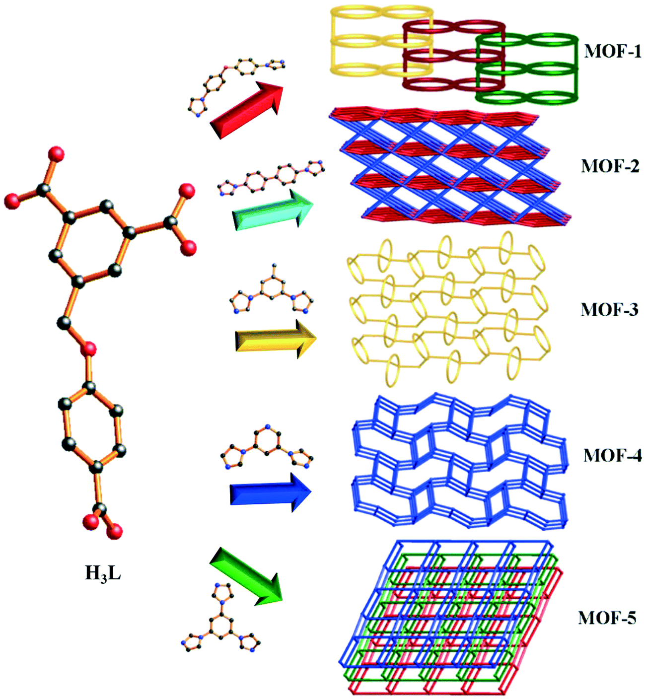 | ||
| Scheme 1 Various polymeric structures of MOFs 1–5. | ||
Experimental section
Materials and physical measurements
All reagents and solvents were obtained from Jinan Henghua Sci. & Tec. Co. Ltd. and were used without further purification. The infrared spectrum was recorded as KBr pellets using a Nicolet 170SX spectrometer in the 4000–400 cm−1 region. Elemental analysis (C, H, and N) was performed using a 2400 model Perkin-Elmer analyzer. Thermogravimetric analysis (TGA) was conducted using a Perkin-Elmer TGA-7 thermogravimetric analyzer under N2 conditions from room temperature to 800 °C with a heating rate of 10 °C min−1. X-ray powder diffraction patterns (XRPD) were collected using a PANalytical X'Pert Pro diffractometer with Cu-Kα radiation. Topological analysis was performed and confirmed using the TOPOS program and the Systre software.21–23Synthesis of {[Co1.5(HL)(4,4′-bidpe)2(H2O)]·3H2O}n (1)
A mixture of H3L (0.032 g, 0.1 mmol), Co(NO3)2·6H2O (0.058 g, 0.2 mmol) and 4,4′-bidpe (0.090 g, 0.2 mmol) was dissolved in 9 mL of DMF/H2O (1![[thin space (1/6-em)]](https://www.rsc.org/images/entities/char_2009.gif) :2, v/v). The final mixture was placed in a Teflon-lined stainless steel vessel, heated to 130 °C, maintained for 3 days, and then cooled (a descent rate of 5 °C h−1) to room temperature. Violet block crystals 1 were obtained with a yield of 60% (based on Co). Anal. (%) calcd. for C52H46Co1.5N8O13: C, 57.86; H, 4.29; N, 10.38. Found: C, 57.62; H, 4.25; N, 10.31. IR (KBr pellet, cm−1): 3619 (w), 3346 (m), 3134 (w), 1602 (s), 1560 (m), 1516 (s), 1450 (w), 1419 (w), 1375 (m), 1357 (s), 1302 (w), 1246 (s), 1171 (m), 1124 (m), 1063 (m), 1033 (w), 1013 (w), 964 (m), 936 (w), 874 (w), 837 (m), 786 (m), 741 (m), 658 (m), 532 (m), 503 (w), 474 (w).
:2, v/v). The final mixture was placed in a Teflon-lined stainless steel vessel, heated to 130 °C, maintained for 3 days, and then cooled (a descent rate of 5 °C h−1) to room temperature. Violet block crystals 1 were obtained with a yield of 60% (based on Co). Anal. (%) calcd. for C52H46Co1.5N8O13: C, 57.86; H, 4.29; N, 10.38. Found: C, 57.62; H, 4.25; N, 10.31. IR (KBr pellet, cm−1): 3619 (w), 3346 (m), 3134 (w), 1602 (s), 1560 (m), 1516 (s), 1450 (w), 1419 (w), 1375 (m), 1357 (s), 1302 (w), 1246 (s), 1171 (m), 1124 (m), 1063 (m), 1033 (w), 1013 (w), 964 (m), 936 (w), 874 (w), 837 (m), 786 (m), 741 (m), 658 (m), 532 (m), 503 (w), 474 (w).
Synthesis of {[Co3(L)2(4,4′-bibp)3(μ2-O)2]·2H2O}n (2)
The synthesis of 2 used the same condition as 1 except that 4,4′-bidpe was replaced by 4,4′-bibp. Brown crystals were collected with a yield of 52% (based on Co). Anal. (%) calcd. for C54H46Co3N10O19: C, 49.29; H, 3.52; N, 10.64. Found: C, 49.22; H, 3.49; N, 10.61. IR (KBr pellet, cm−1): 3619 (w), 3116 (m), 1590 (m), 1558 (m), 1516 (s), 1446 (m), 1385 (m), 1364 (m), 1310 (m), 1236 (m), 1163 (w), 1129 (w), 1061 (m), 960 (m), 936 (w), 823 (m), 770 (m), 703 (w), 648 (m), 535 (m).Synthesis of {[Co(HL)(1,3-bitl)]·(1,4-Diox)}n (3)
A mixture of H3L (0.032 g, 0.1 mmol), Co(NO3)2·6H2O (0.058 g, 0.2 mmol) and 1,3-bitl (0.046 g, 0.2 mmol) was dissolved in 8 mL of 1,4-diox/H2O (1:1, v/v). The final mixture was placed in a Teflon-lined stainless steel vessel, heated to 130 °C, maintained for 3 days, and then cooled (a descent rate of 5 °C h−1) to room temperature. Violet block crystals 3 were obtained with a yield of 51% (based on Co). Anal. (%) calcd. for C33H30CoN4O9: C, 57.81; H, 4.41; N, 8.17. Found: C, 57.77; H, 4.38; N, 8.12. IR (KBr pellet, cm−1): 3429 (w), 3126 (m), 2942 (w), 1683 (m), 1623 (m), 1606 (s), 1548 (s), 1508 (m), 1460 (w), 1439 (m), 1417 (w), 1378 (m), 1355 (s), 1320 (w), 1249 (s), 1168 (m), 1108 (m), 1081 (m), 1070 (m), 1004 (m), 946 (m), 910 (w), 889 (w), 871 (m), 843 (m), 825 (w), 777 (m), 765 (m), 733 (m), 684 (m), 651 (m), 631 (w), 614 (w), 554 (w), 532 (w).
Synthesis of [Co2(HL)2(3,5-bipd)2]n (4)
A mixture of H3L (0.032 g, 0.1 mmol), Co(NO3)2·6H2O (0.058 g, 0.2 mmol) and 3,5-bipd (0.047 g, 0.2 mmol) was dissolved in 8 mL of DMF/H2O (1:1, v/v). The final mixture was placed in a Teflon-lined stainless steel vessel, heated to 130 °C, maintained for 3 days, and then cooled (a descent rate of 5 °C h−1) to room temperature. Violet block crystals 4 were obtained with a yield of 58% (based on Co). Anal. (%) calcd. for C54H38Co2N10O14: C, 55.49; H, 3.27; N, 11.98. Found: C, 55.45; H, 3.23; N, 11.95. IR (KBr pellet, cm−1): 3136 (m), 3053 (w), 3074 (w), 1681 (m), 1606 (m), 1560 (s), 1507 (m), 1447 (m), 1390 (s), 1319 (w), 1294 (w), 1263 (w), 1240 (s), 1215 (m), 1170 (m), 1108 (m), 1062 (m), 1010 (m), 958 (m), 936 (m), 901 (w), 881 (w), 853 (m), 837 (m), 807 (m), 777 (s), 731 (m), 692 (w), 651 (m), 631 (w), 589 (m), 541 (w).
Synthesis of {[Co(HL)(tib)]·0.5H2O·NMP}n (5)
A mixture of H3L (0.032 g, 0.1 mmol), Co(NO3)2·6H2O (0.058 g, 0.2 mmol) and tib (0.058 g, 0.2 mmol) was dissolved in 9 mL of NMP/H2O (1:1, v/v). The final mixture was placed in a Teflon-lined stainless steel vessel, heated to 130 °C, maintained for 3 days, and then cooled (a descent rate of 5 °C h−1) to room temperature. Red block crystals 5 were obtained with a yield of 53% (based on Co). Anal. (%) calcd. for C72H64Co2N14O17: C, 57.07; H, 4.25; N, 12.94. Found: C, 57.02; H, 4.22; N, 12.89. IR (KBr pellet, cm−1): 3448 (w), 3134 (w), 2871 (w), 1685 (s), 1616 (s), 1606 (m), 1569 (m), 1538 (m), 1507 (s), 1448 (m), 1381 (m), 1303 (w), 1286 (w), 1241 (m), 1168 (m), 1107 (w), 1075 (m), 1014 (m), 933 (m), 903 (w), 863 (w), 846 (w), 777 (w), 763 (m), 729 (m), 682 (m), 653 (m), 533 (w), 503 (w).
X-ray crystallography
X-ray crystallography data of complexes 1–5 were collected using a Bruker Apex Smart CCD diffractometer at 293(2) K with graphite-monochromated Mo-Kα radiation (λ = 0.71073 Å) by using the ω–2θ scan mode. The structure was solved by direct methods using SHELXS-97.24 The non-hydrogen atoms were defined by the Fourier synthesis method. Positional and thermal parameters were refined by the full matrix least-squares method (on F2) to convergence.25 Crystallographic data for complexes 1–5 are given in Table 1. The selected bond lengths and angles for 1–5 are listed in Table S1.† CCDC numbers for complexes of 1–5 are 1559878 for 1, 1519484 for 2, 1559879 for 3, 1519483 for 4 and 1559880 for 5.| Compound | 1 | 2 | 3 | 4 | 5 |
|---|---|---|---|---|---|
| a R 1 = ∑‖Fo| − |Fc‖/∑|Fo|, wR2 = [∑w(Fo2 − Fc2)2]/[∑w(Fo2)2]1/2. | |||||
| Empirical formula | C104H92Co3N16O26 | C86H62Co3N12O18 | C33H30CoN4O9 | C54H38Co2N10O14 | C72H64Co2N14O17 |
| Formula weight | 2158.72 | 1728.26 | 685.54 | 1168.80 | 1515.23 |
| Crystal system | Triclinic | Triclinic | Monoclinic | Triclinic | Triclinic |
| Space group |
P![[1 with combining macron]](https://www.rsc.org/images/entities/char_0031_0304.gif) |
P |
P21/c |
P |
P |
| a (Å) | 11.5476(14) | 10.8519(4) | 14.315(2) | 9.9822(3) | 9.8268(9) |
| b (Å) | 14.6312(19) | 12.0078(4) | 12.4647(17) | 14.2046(4) | 13.2214(12) |
| c (Å) | 15.3494(18) | 16.0618(6) | 18.515(3) | 18.0644(5) | 14.1027(13) |
| α (°) | 96.828(3) | 72.122(2) | 90 | 88.116(2) | 90.290(2) |
| β (°) | 97.036(3) | 88.959(2) | 109.826(2) | 85.266(2) | 104.858(2) |
| γ (°) | 108.059(2) | 71.729(2) | 90 | 73.8020(10) | 108.809(2) |
| V (Å3) | 2413.0(5) | 1884.41(12) | 3108.0(7) | 2451.21(12) | 1668.7(3) |
| Z | 1 | 1 | 4 | 2 | 1 |
| D calcd (Mg m−3) | 1.486 | 1.523 | 1.465 | 1.584 | 1.508 |
| μ (mm−1) | 0.599 | 0.736 | 0.615 | 0.760 | 0.582 |
| Reflections collected | 18517 |
19575 |
26661 |
11116 |
12740 |
| Data/parameters | 8820/687 | 6892/541 | 7127/426 | 11116/723 |
6215/541 |
| F(000) | 1117 | 887 | 1420 | 1196 | 784 |
| T (K) | 205(2) | 170(2) | 296(2) | 296(2) | 205(2) |
| R int | 0.0441 | 0.0195 | 0.0320 | 0 | 0.0257 |
| Final R indices [I > 2σ(I)] | R 1 = 0.0484 | R 1 = 0.0307 | R 1 = 0.0398 | R 1 = 0.0733 | R 1 = 0.0386 |
| wR2 = 0.1279 | wR2 = 0.0935 | wR2 = 0.1146 | wR2 = 0.2228 | wR2 = 0.1138 | |
| R indices (all data) | R 1 = 0.0776 | R 1 = 0.0346 | R 1 = 0.0482 | R 1 = 0.0.1035 | R 1 = 0.0447 |
| wR2 = 0.1413 | wR2 = 0.0964 | wR2 = 0.1215 | wR2 = 0.2419 | wR2 = 0.1193 | |
| Gof | 0.991 | 1.055 | 1.029 | 1.059 | 1.004 |
Results and discussion
Synthesis and characterization
In this work, the synthesis of complexes 1–5 was constructed from H3L and the related Co(II) salt in the presence of five N-donor (4,4′-bidpe, 4,4′-bibp, 1,3-bitl, 3,5-bipd and tib) bridging linkers under solvothermal conditions. These complexes, 1–5, are stable in the solid state upon extended exposure to air. Meanwhile, all of the complexes 1–5 have poor solubility in water and common organic solvent, but can be slightly soluble in very high polarity solvents.Structure description of {[Co1.5(HL)(4,4′-bidpe)2(H2O)]·3H2O}n (1)
Single-crystal X-ray diffraction shows that compound 1 crystallizes in the triclinic space group P. In the asymmetric unit, there exist one and a half Co(II) centers (two types of Co(II) ions (Co1 and Co2); occupancy ratio: one for Co2 and a half for Co1), one HL2− anion, two 4,4′-bidpe ligands and one coordinated water molecule. As shown in Fig. 1a, the Co1 atom is six-coordinated, coordinated by four N atoms from four independent 4,4′-bidpe ligands and two O atoms from two coordination water molecules, displaying a slightly distorted octahedral coordination geometry. Meanwhile, the Co2 atom is four-coordinated by two O atoms from two independent HL2− ligands and two N atoms from two different 4,4′-bidpe ligands, forming a slightly distorted tetrahedral coordination geometry. The bond lengths of Co–O and Co–N vary between 1.941(2)–2.118(2) Å and 2.012(3)–2.159(3) Å, respectively.
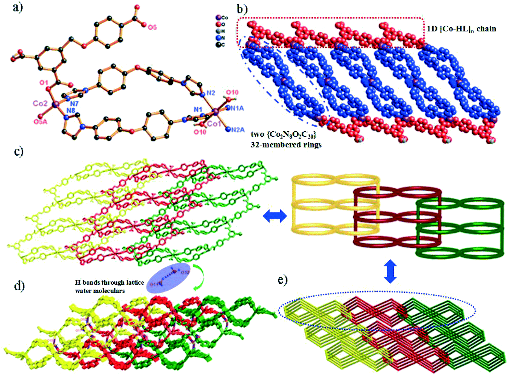 | ||
| Fig. 1 (a) Coordination environment of the Co(II) ion in complex 1 (symmetry codes: i: −x + 2, −y + 2, −z; ii: x, y − 1, z). (b) View of the 1D chain of 1 (blue spheres: 4,4′-bidpe ligands; red spheres: HL2− ligands). (c) The rarely 1D → 2D polyrotaxane networks and the 2D loop structure. (d) View of the 3D supramolecular structure through H-bonds. (e) The 3-nodal (2,4,4)-connected 3D topology structure in complex 1. | ||
In complex 1, two adjacent Co2 ions are connected by a partially deprotonated HL2− ligand, which shows a μ2-(κ1-κ0)-(κ1-κ0) coordination mode (Scheme 2, mode I), constructing a 1D [Co–HL]n linear chain. Interestingly, three neighbouring Co(II) ions (one Co1 and two Co2) are bridged through four 4,4′-bidpe ligands, forming two same loops ({Co2N8O2C20} 32-membered ring). The adjacent loop and [Co–HL]n chain connected each other by sharing the same Co2 ion, further constructing a 1D loop chain (Fig. 1b). The parallel 1D loop chains interconnect with each other, finally forming a rare 1D → 2D polyrotaxane layer (Fig. 1c). Furthermore, the 2D polyrotaxane layer further interacted with the neighbouring polyrotaxane layer through H-bonds, finally resulting in a 3D supramolecular structure (Fig. 1d). Moreover, with the lattice H2O molecules being omitted, the calculation using PLATON shows that the void volume of 1 is 5.8% of the crystal volume (140.1 Å3 out of the 2413.0 Å3 unit cell volume).26 From a topological view, the whole structure exhibits a 3-nodal (2,4,4)-connected 3D supramolecular structure (Fig. 1e).
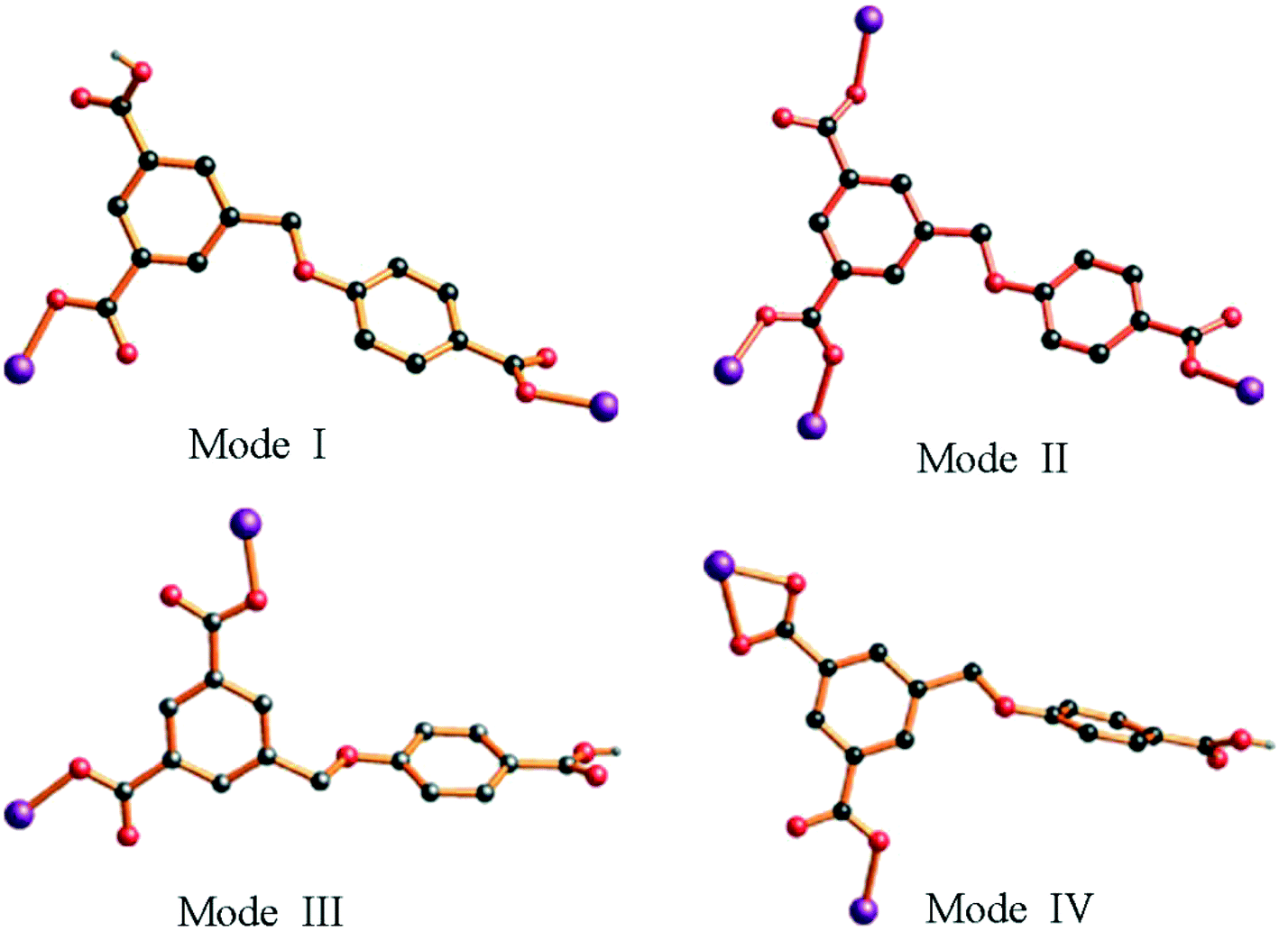 | ||
| Scheme 2 Diverse coordination modes of H3L in MOFs 1–5. | ||
Structure description of {[Co3(L)2(4,4′-bibp)3(μ2-O)2]·2H2O}n (2)
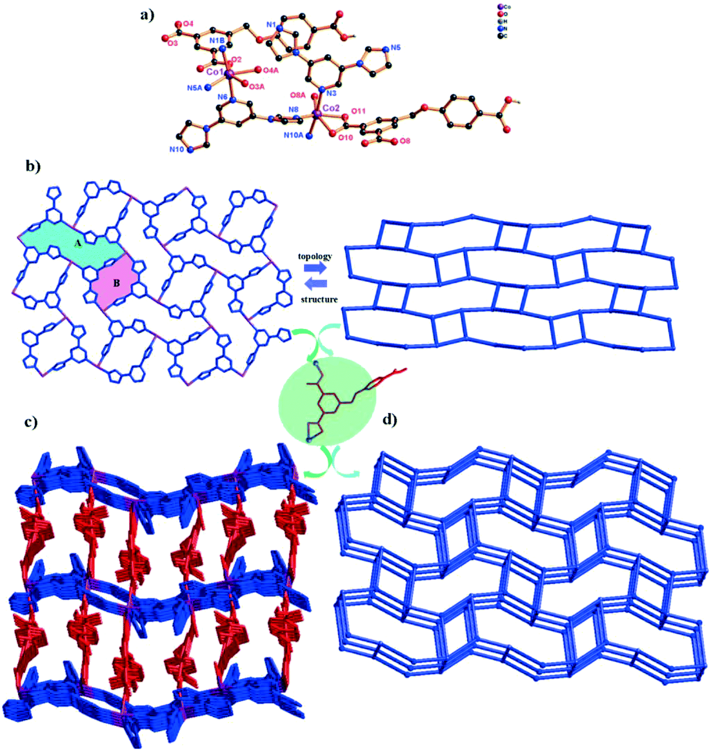
Complex 2 exhibits a 3D Co(II) metal–organic framework with trinuclear metal–oxygen clusters. Complex 2 crystallizes in the triclinic system space group P. In its asymmetric unit, there are two types of Co(II) ions (two Co1 ions and one Co2 ion), two completely deprotonated L3− anions, three 4,4′-bibp auxiliary ligands and two μ2-O. As shown in Fig. 2a, the Co1 atom is hexa-coordinated by two N atoms from two individual 4,4′-bibp ligands, three O atoms from three different L3− ligands and one O atom from μ2-O. Meanwhile, the Co2 atom also is six-coordinated, coordinated by two N atoms from two independent 4,4′-bibp ligands, two O atoms from two L3− ligands and two O atom from two μ2-O. Three crystallographically distinct Co(II) ions are bound together by two μ2-(κ1-κ1) carboxylate groups and two μ2-O to form trinuclear [Co3(μ2-O)2(COO)2] clusters, which can be defined as SBUs. The bond lengths of Co–O and Co–N are in the range of 2.049(12)–2.199(13) Å and 2.098(16)–2.108(16) Å, respectively. Furthermore, the intermetallic distance separated by the μ2-O and μ2-(κ1-κ1) carboxylate group is 3.756(3) Å (Co1⋯Co2).
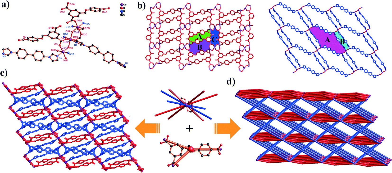 | ||
| Fig. 2 (a) Coordination environment of the Co(II) ion in complex 2 (symmetry codes: i: x + 1, y, z; ii: −x + 1, −y, −z + 2; iii: −x, −y, −z + 1; iv: x − 1, y, z). (b) View of the 2D kgd [Co3(L3−)2]n network and 2D sql [Co3(4,4′-bibp)2]n6n+ network (blue spheres: 4,4′-bibp ligands; red spheres: L3− ligands). (c) The 3D framework of 2. (d) View of the unprecedented 2-nodal (3,10)-connected 3D framework with a (43)2(46·632·83)(43)2 topology. | ||
In complex 2, H3L ligands are completely deprotonated with the μ4-(κ1-κ1)-(κ1-κ0)-(κ1-κ0) coordination mode (Scheme 2, mode II). The completely deprotonated H3L ligands connect the adjacent three [Co3(μ2-O)2(COO)2]4+ SBUs to construct a 2D kgd network with a point symbol of (43)2(46·68·83). When the H3L ligands are ignored, the neighbouring two [Co3(μ2-O)2(COO)2] SBUs are connected by N-donor ligands, showing a 2D sql network with an –A–B–A– fashion (Fig. 2b and S1†). Furthermore, two different networks selectively connect each other, forming a stable 3D framework (Fig. 2c). The effective free volume of 2 was 1.8% of the crystal volume (34.3 Å3 out of the 1884.4 Å3 unit cell volume), calculated using PLATON.26
From a topological view, the trinuclear [Co3(μ2-O)2(COO)2] cluster can be viewed as a ten-connector, while the H3L ligands can be viewed as a three-connector. Thus, the 3D framework acquired can be simplified as an unprecedented 2-nodal (3,10)-connected metal–organic framework with a (43)2(46·632·83)(43)2 topology (Fig. 2d).
Structure description of {[Co(HL)(1,3-bitl)]·(1,4-Diox)}n (3)
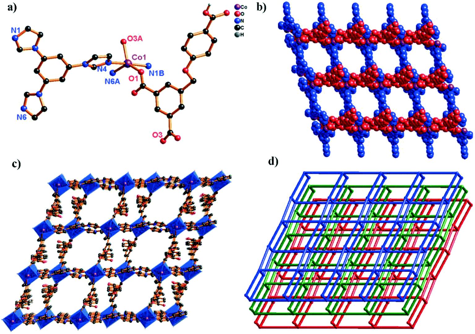
The crystal structure determined by single-crystal X-ray diffraction reveals that complex 3 crystallizes in the monoclinic system, space group P21/c. The asymmetric unit of 3 contains one Co(II) cation, one HL2− ligand and one 1,3-bitl N-donor ligand. As depicted in Fig. 3a, the coordination environment around the Co(II) atom is composed of two O atoms from two different HL2− ligands and two N atoms from two independent 1,3-bitl ligands, exhibiting a distorted tetrahedral geometry. The Co–O bond distances are 1.9643(14) (Co1–O2) and 1.9642(14) Å (Co1–O4i), and the Co–N bond distances are 2.0210(17) (Co1–N1) and 2.0412(16) Å (Co1–N4ii), respectively.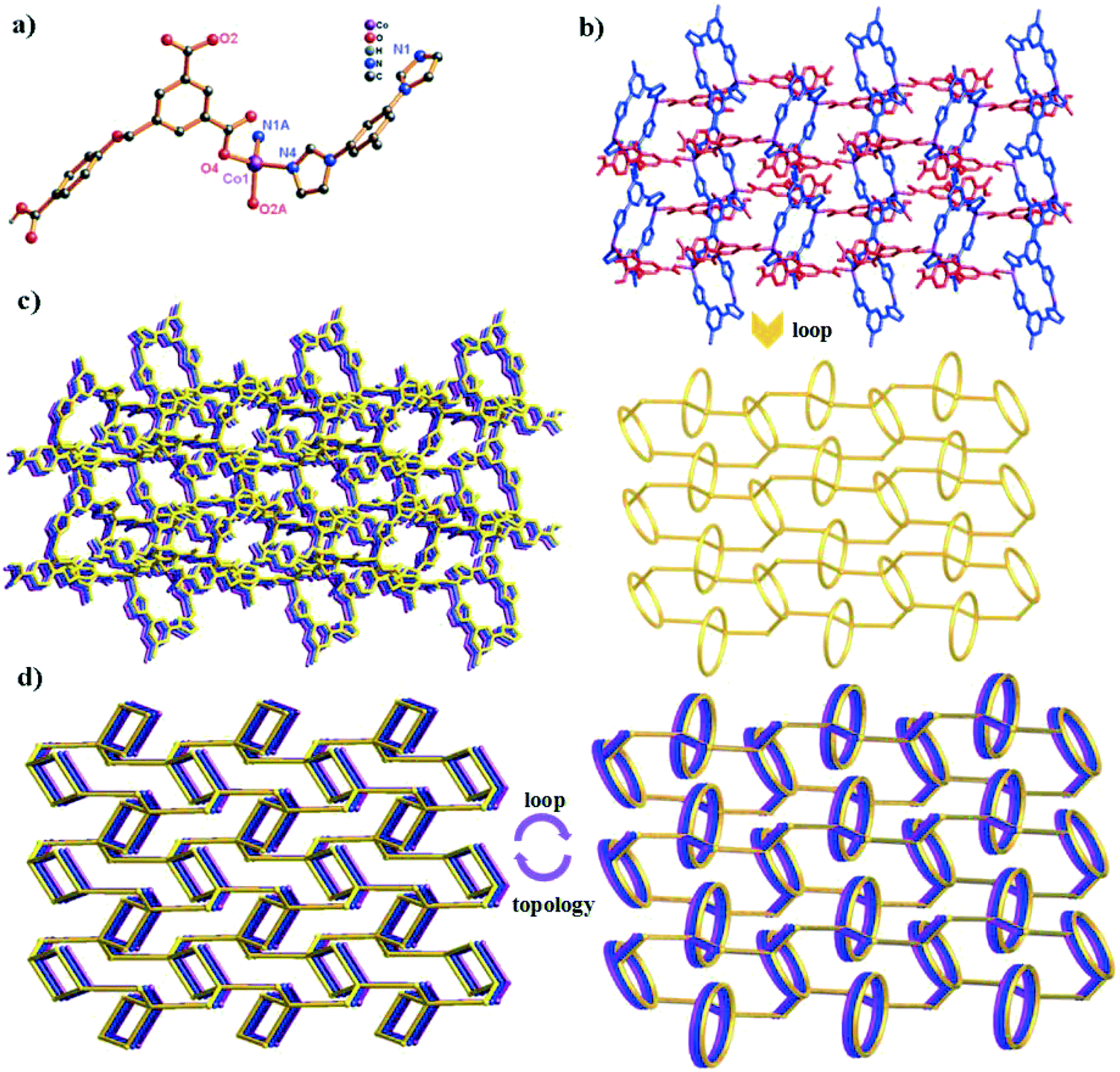 | ||
| Fig. 3 (a) Coordination environment of the Co(II) ion in complex 3 (symmetry codes: i: x, −y + 1/2, z + 1/2; ii: −x + 2, −y + 1, −z + 2; iii: x, −y + 1/2, z − 1/2). (b) View of the 2D topology network and 2D loop network in complex 3 (blue spheres: 1,3-bitl ligands; red spheres: HL2− ligands). (c) The 2D → 3D supramolecular networks through H-bonds. (d) View of the (2,2,4)-connected 3D supramolecular framework. | ||
Similar to 1, adjacent Co(II) ions are also bridged by the partially deprotonated HL2− ligands (coordination mode: μ2-(κ1-κ0)-(κ1-κ0); Scheme 2, mode III) to form a 1D [Co–HL]n liner chain in 3. However, in 3, two neighbouring Co1 ions are bridged through two 1,3-bitl ligands, forming an independent loop ({Co2N8C10} 20-membered ring). These independent {Co2N8C10} loops are connected by HL2− ligands, constructing a 2D network (Fig. 3b). The adjacent 2D networks further interacted with each other through H-bonds, constructing a 3D supramolecular structure (Fig. 3c and S2†). Furthermore, with the guest 1,4-diox molecules being omitted, the calculation using PLATON shows that the void volume of 3 is 20.8% of the crystal volume (645.4 Å3 out of the 3108.0 Å3 unit cell volume).26 From a topological view, the Co(II) ion can be considered as a 4-connected node, and two “V”-shaped spacers (HL2− and 1,3-bitl) can be considered as 2-connected node. Thus, the final 3D supramolecular framework can be classified as a (2,2,4)-connected network (Fig. 3d).
Structure description of [Co2(HL)2(3,5-bipd)2]n (4)
In order to investigate the effect of auxiliary ligand configuration on the final structure, the 3,5-bipd ligand was employed in the mixed system. And another framework 4 was obtained. It crystallizes in the triclinic space group P, and the asymmetric unit consists of two different types of Co(II) ions (Co1 and Co2), two HL2− ligands and two 3,5-bipd ligands. As shown in Fig. 4a, the environment around Co1 can be described as a slightly distorted octahedral geometry, coordinated by three O atoms from two different HL2− ligands and three N atoms from three independent 3,5-bipd ligands. Interestingly, Co2 shows the same coordination environment as Co1. The Co–O bond distances are in the range of 2.016(3)–2.387(4) Å, and the Co–N bond distances are in the range of 2.079(3)–2.262(3) Å, respectively.
 | ||
| Fig. 4 (a) Coordination environment of the Co(II) ion in complex 4 (symmetry codes: i: x + 1, y, z; ii: −x + 1, −y + 1, −z + 1; iii: x − 1, y, z; iv: x, y, z − 1). (b) View of the 3-connected fes 2D [Co(3,5-bipd)]n2n+ network in 4. (c) The 3D framework of complex 4 (blue spheres: 3,5-bipd ligands; red spheres: HL2− ligands). (d) View of the unprecedented 2-nodal (3,5)-connected 3D framework with the Schläfli symbol (4·62)(4·66·83). | ||
The H3L ligand in complex 4 is also partially deprotonated and exhibits a μ2-(κ1-κ1)-(κ1-κ0) coordination mode (Scheme 2, mode IV). Three adjacent Co(II) ions are bridged by μ3-bipd ligand to generate 3-connected fes 2D networks with two different windows (Fig. 4b). These 2D networks are further linked by HL2− ligands to generate a more complicated 3D framework (Fig. 4c). The effective free volume of 4 was 2.1% of the crystal volume (51.3 Å3 out of the 2451.2 Å3 unit cell volume), calculated using PLATON.26
From the viewpoint of structural topology, the whole 3D structure exhibits an unprecedented 2-nodal (3,5)-connected 3D framework with a (4·62)(4·66·83) topology (Fig. 4d).
Structure description of {[Co(HL)(tib)]·0.5H2O·NMP}n (5)
When the 3,5-bipd ligand was replaced by another tris(imidazole) linker (tib), an unprecedented 3D supramolecular framework was obtained. Structure analysis reveals that complex 5 crystallizes in the triclinic system, space group P. In the asymmetric unit, there exists one crystallographically unique Co(II) atom, one HL2− ligand and one tib N-donor ligand. As shown in Fig. 5a, the Co(II) center shows a rare five-coordinated environment, ligated by two O atoms from two different HL2− ligands and three N atoms from three independent tib ligands. The Co–O bond distances are 2.0686(16) (Co1–O1) and 2.0917(17) Å (Co1–O3i), and the Co–N bond distances are 2.1185(17) (Co1–N1), 2.1207(18) (Co1–N4iii), and 2.1127(18) Å (Co1–N6ii), respectively.
 | ||
| Fig. 5 (a) Coordination environment of the Co(II) ion in complex 5 (symmetry codes: i: x + 1, y, z; ii: −x + 1, −y + 1, −z + 2; iii: x, y − 1, z; iv: x − 1, y, z). (b) View of the unprecedented 2-nodal (3,5)-connected 2D network in 5 (blue spheres: tib ligands; red spheres: HL2− ligands). (c) The 2D → 3D supramolecular framework through H-bonds. (d) The 3D topology structure of 5 with the point symbol (42·67·8)(42·6). | ||
In complex 5, the H3L ligand shows the same coordination mode as 3 (Scheme 2, mode III). Two adjacent Co(II) atoms are connected by the partially deprotonated HL2− ligand, which constructs a 1D [Co–HL]n chain. Meanwhile, the μ3-tib N-donor ligand bridging three neighbouring Co(II) atoms further constructed a 1D [Co–tib]n ladder chain with a 5.9960(27) × 6.2379(25) Å2 window. Furthermore, those two different chains interact with each other through Co1 ions, forming an unprecedented 2-nodal (3,5)-connected 2D network (Fig. 5b). Two adjacent 2D networks further connect each other through H-bonds (O6–H6⋯O2), constructing another stable 3D supramolecular framework (Fig. 5c and S3†). Furthermore, with the guest H2O and NMP molecules being omitted, the calculation using PLATON shows that the void volume of 5 is 23.5% of the crystal volume (391.8 Å3 out of the 1668.7 Å3 unit cell volume).26 Based on the concept of topology, the whole structure can be classified into an unprecedented 2-nodal (3,5)-connected 3D supramolecular framework with a (42·67·8)(42·6) topology (Fig. 5d).
Structural comparison and discussion
As is well known, the flexibility of the carboxylate ligands, the central metals and the configuration of N-donor ligands play a key role in the construction of the structures of MOFs. As shown in Scheme 2 and Fig. S4,† H3L exhibits versatile coordination modes and different dihedral angles between the two phenyl rings in H3L, which further results in a series of novel topologies. Although complexes 1, 3 and 5 exhibit the same coordination mode (μ2-(κ1-κ0)-(κ1-κ0)), the dihedral angle of these complexes are different (42.17(3)° for 1, 68.72(2)° for 3 and 61.19(2)° for 5). Meanwhile, compared with 3 and 5, the two coordinated carboxyl groups are obtained from two different phenyl rings in 1. In complex 2, the H3L ligands show a completely deprotonated mode (μ4-(κ1-κ1)-(κ1-κ0)-(κ1-κ0)) with a 22.90(1)° dihedral angle. In complex 4, the H3L ligands show a different partially deprotonated coordination mode (μ2-(κ1-κ1)-(κ1-κ0)), and the dihedral angle between two phenyl rings is the biggest one (75.98(3)°). Interestingly, both the biggest (4) and the smallest (2) dihedral angle of the H3L ligands show a 3D framework through connecting with N-donor ligands. Therefore, we considered that the flexibility of H3L ligands could deeply influence the final architecture.As is well known, the different lengths and configurations of N-donor ligands greatly influence the final structure.27 Except for 1 being a semi-flexible-auxiliary ligand, the N-donor ligands can be seen as rigid-auxiliary ligands in complexes 2–5. Therefore, only complex 1 shows a rare 1D → 2D polyrotaxane network, and complexes 2–5 show an unprecedented 3D framework, a 2D network, a 3D unprecedented framework and a 2D unprecedented network, respectively. Meanwhile, influenced by the configuration of the N-donor ligands, complexes 1, 3, 4 and 5 have one uncoordinated carboxyl groups, while complex 2 have uncoordinated oxygen atoms. Moreover, the pore sizes of complexes 1–5 are different due to the configuration of the N-donor ligands. Thus, complexes 1–5 can be used to investigate the adsorption capacity, which is affected by their different structures.
Thermal analyses
To estimate the thermal stabilities of compounds 1–5, their thermal behaviors were investigated by thermogravimetric analyses (TGA) under a N2 atmosphere at a heating rate of 10 °C min−1 (Fig. S5†). The TG curves of 1 and 2 exhibit a good resemblance. The first weight loss was from room temperature to 240 °C for 1 (obsd: 6.59%, calcd: 6.67%) and from 100–240 °C for 2 (obsd: 2.02%, calcd: 2.08%), corresponding to the removal of the lattice H2O and/or coordinated H2O molecules. The second weight loss corresponds to the loss of the organic ligands at ca. 335 °C for 1 and ca. 270 °C for 2. The remaining weight corresponds to the formation of CoO (obsd: 32.65% calcd: 10.42% for 1; obsd: 42.49%, calcd: 13.02% for 2). There is no lattice solvent molecule in 3 and 4, therefore, the TG curves exhibit plateaus before 305 °C for 3 and 360 °C for 4, and then the pyrolysis of the framework took place. The remaining weight corresponds to the formation of CoO (obsd: 29.19%, calcd: 10.94% for 3; obsd: 28.26%, calcd: 12.84% for 4). For complex 5, the first weight loss in the temperature range of 180–240 °C is consistent with the removal of the lattice NMP and H2O molecules (obsd: 12.42%, calcd: 12.82%). The second weight loss corresponds to the loss of the organic ligands at ca. 350 °C. The remaining weight corresponds to the formation of CoO (obsd: 37.31%, calcd: 9.90%). The larger CoO remaining weight (obsd) may be caused by the incomplete decomposition of compounds 1–5 under 800 °C.UV-visible spectra of complexes 1–5
Based on the different colors of complexes 1–5, their solid state UV-vis adsorption spectra were measured at room temperature (Fig. S6†). The spectra of complexes 1–5 show two wide absorption bands in the range of 235–420 nm and 430–640 nm, respectively. And the absorption band from 235–420 nm should be considered as π–π* transitions of the ligands.28 Another absorption band from 430–625 nm can be ascribed to the spin-allowed d–d electronic transitions of the d7 (Co2+) cation.29 The different colors of complexes 1–5 are caused by the absorption band and absorption intensity.Magnetic properties of 2 and 4
The magnetic susceptibility measurements were taken in the temperature range of 2–300 K under an applied field of 1000 Oe. For complex 2, as shown in Fig. 6, the χMT value is 9.98 at 300 K, which is almost twice higher than the expected value for three high-spin Co(II) ions (5.63 cm3 K mol−1, S = 3/2, g = 2.0). When the temperature is lowered, the χMT value decreased gradually and reached the value of 0.68 cm3 K mol−1 at 2 K. Meanwhile, the χM value increases continuously along with the decrease in temperature. These results clearly manifest that the presence of antiferromagnetic coupling between octahedral Co(II) ions and the structure of the [Co3(μ2-O)2N6(COO)2] trinuclear cluster may be responsible for this phenomenon.30–32 Meanwhile, the temperature dependence of the reciprocal susceptibilities (χM−1) was plotted and it obeys well the Curie–Weiss law above 15 K, with C = 11.11 cm3 K mol−1 and θ = −32.28 K. The negative θ values reveals the dominant antiferromagnetic interactions between the Co(II) ions or the presence of spin–orbit coupling.33 For complex 4, the χMT value is 2.31 at 300 K, which is larger than that for magnetically isolated spin-only Co(II) ions (1.88 cm3 K mol−1, S = 3/2, g = 2.0). As the sample was cooling down, the χMT value falls slowly until about 65 K and decreases sharply to 1.49 cm3 K mol−1 at 2 K (Fig. 6). This result reveals the presence of antiferromagnetic interaction between neighboring Co(II) ions. Meanwhile, the magnetic susceptibilities (χM−1) also perfectly obey the Curie–Weiss law in the temperature range of 2–300 K, with C = 2.34 cm3 K mol−1 and θ = −2.63 K. Both the negative θ and the decrease of χMT can be attributed to the antiferromagnetic coupling interactions between the neighboring Co(II) ions.34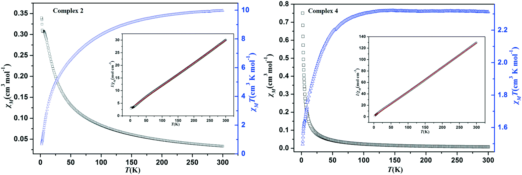 | ||
| Fig. 6 Temperature dependence of χMT and χM for complexes 2 (left) and 4 (right) from 2 to 300 K under 1000 Oe field. Inset: Temperature dependence of χM−1. The red solid lines represent the fitting results of the Curie–Weiss law χM = C/(T − θ). | ||
Dyes adsorption and mechanism
Based on the different channels and pores of the titled MOFs, the investigation of guest capture in solution to explore the porosity and its potential application seems to be promising. In our work, three organic dyes (Fig. S7,† acriflavine hydrochloride (AH), methyl orange (MO) and Congo red (GR)) with different functional groups (–CH3 or –NH2) and molecular sizes were selected to investigate their influence on dye adsorption.35,36 5 mg of MOFs were dispersed in a 5 mL aqueous solution of AH, MO or GR at a concentration of 20 ppm. Upon adsorption, the solution was tested at certain time intervals using UV-vis absorption spectroscopy.The adsorption behaviors of five MOFs toward three kinds of organic dye aqueous solutions are shown in Fig. 7 and 8 and S8.† As shown in Fig. 7, AH could be totally absorbed by the titled MOFs (1–5) after different adsorption times, and the removal percentage (%) of AH can be calculated using the following equation: [AH removal] = (c0 − c1)/c0, where c0 and c1 represent the initial and final concentrations of the dye solution, respectively. After calculation, the AH adsorption rates are 92.80% for MOF-1 (after 540 min), 91.33% for MOF-2 (after 540 min), 92.17% for MOF-3 (after 240 min), 90.02% for MOF-4 (after 360 min) and 90.64% for MOF-5 (after 480 min), respectively. The UV-vis curves of Fig. 8 exhibit that GR could also be absorbed by MOFs 1–5. MOF-3 (91.80% after 480 min) shows a better adsorption capacity for GR than the other four MOFs (91.86% for 1, 91.04% for 2, 78.75% for 4 and 70.81% for 5 after 600 min). As shown in Fig. S8,† MOF-2 exhibits an excellent capacity to absorb MO, while MOF-1, MOF-3, MOF-4 and MOF-5 exhibit no obvious adsorption for MO. Meanwhile, the crystal color changes of MOFs 1–5 after dye adsorption also indicate the adsorption process. Moreover, the adsorption capacity comparison of compounds 1–5 with other reported MOFs is shown in Table S2.†16c,19a,20,29,37–40
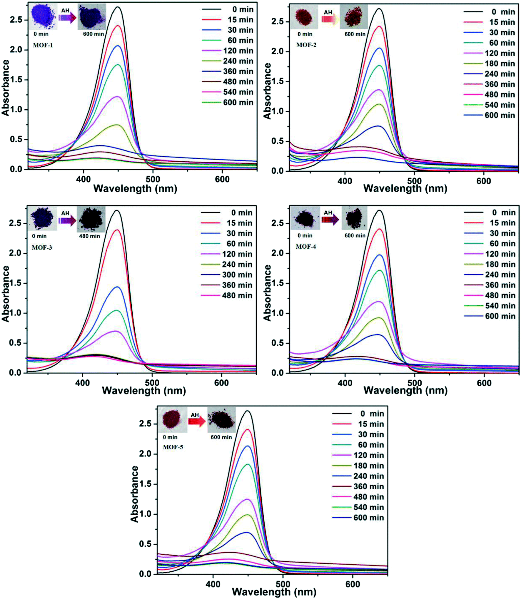 | ||
| Fig. 7 UV-vis spectra for the uptake of AH from aqueous solutions at various time intervals for 1–5, respectively. The inset photographic images show the color change of MOFs before and after the adsorption of AH. | ||
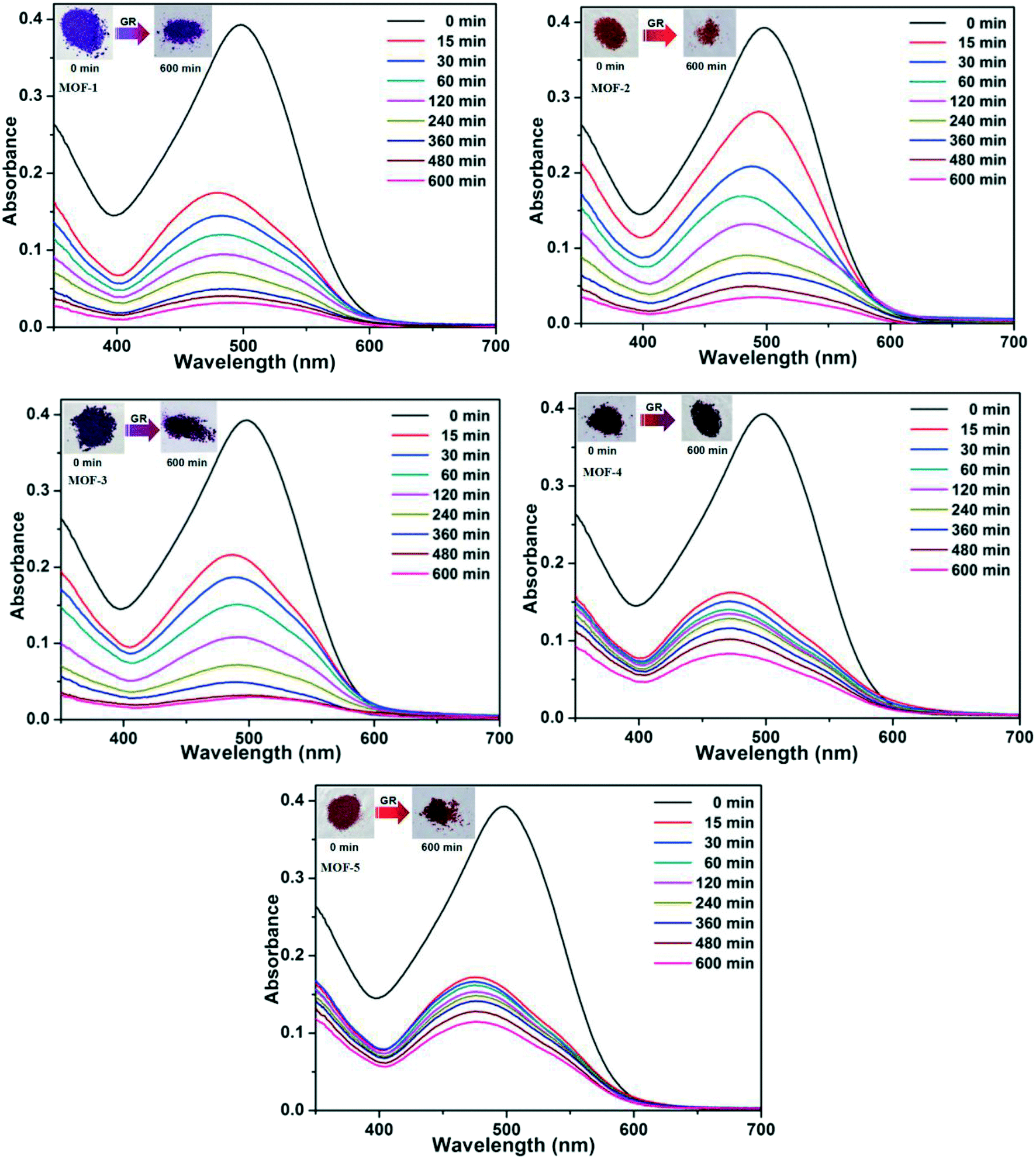 | ||
| Fig. 8 UV-vis spectra for the uptake of GR from aqueous solutions at various time intervals for 1–5, respectively. The inset photographic images show the color change of MOFs before and after the adsorption of GR. | ||
As is well known, the porous MOFs can absorb organic dyes, which could be attributed to the chemical interactions41 or physical forces42 between organic dyes and MOFs. Thus, for the amino organic dyes (AH and GR), the possible adsorption mechanism could be explained using the strong interactions between amino organic dyes and MOFs. Because the –NH2 groups are both donors and acceptors of H-bonds, they can facilitate interactions with the specific MOFs (Fig. S9†). As shown in Fig. S10,† the C![[double bond, length as m-dash]](https://www.rsc.org/images/entities/char_e001.gif) O vibration peaks of carboxylate groups from the titled MOFs can be observed at 1602 cm−1 (MOF-1), 1590 cm−1 (MOF-2), 1683 cm−1 (MOF-3), 1681 cm−1 (MOF-4) and 1685 cm−1 (MOF-5), respectively. These CO vibration peaks shift to 1593 cm−1 (MOF-1), 1583 cm−1 (MOF-2), 1674 cm−1 (MOF-3), 1674 cm−1 (MOF-4), and 1676 cm−1 (MOF-5) after AH adsorption, and shift to 1595 cm−1 (MOF-1), 1581 cm−1 (MOF-2), 1679 cm−1 (MOF-3), 1673 cm−1 (MOF-4) and 1679 cm−1 (MOF-5) after GR adsorption. Meanwhile, the N–H vibration peaks of NH2 from AH and GR can be observed at 3302 cm−1 and 3464 cm−1, which further shift to 3286 cm−1 (MOF-1), 3285 cm−1 (MOF-2), 3290 cm−1 (MOF-3), 3294 cm−1 (MOF-4), and 3293 cm−1 (MOF-5) after AH adsorption, and shift to 3386 cm−1 (MOF-1), 3451 cm−1 (MOF-2), 3451 cm−1 (MOF-3), 3448 cm−1 (MOF-4) and 3450 cm−1 (MOF-5) after GR adsorption. Based on what have been mentioned above, we believe that the H-bonds between the –NH2 groups (from amino organic dyes) and the uncoordinated O atoms in carboxyl groups and uncoordinated –COOH groups play a key role in the adsorption of organic dyes. Furthermore, MOF-4 and MOF-5 show a better adsorption capacity for AH than for GR, which may be caused by the different structures of organic dyes and MOFs (Fig. S11†).
O vibration peaks of carboxylate groups from the titled MOFs can be observed at 1602 cm−1 (MOF-1), 1590 cm−1 (MOF-2), 1683 cm−1 (MOF-3), 1681 cm−1 (MOF-4) and 1685 cm−1 (MOF-5), respectively. These CO vibration peaks shift to 1593 cm−1 (MOF-1), 1583 cm−1 (MOF-2), 1674 cm−1 (MOF-3), 1674 cm−1 (MOF-4), and 1676 cm−1 (MOF-5) after AH adsorption, and shift to 1595 cm−1 (MOF-1), 1581 cm−1 (MOF-2), 1679 cm−1 (MOF-3), 1673 cm−1 (MOF-4) and 1679 cm−1 (MOF-5) after GR adsorption. Meanwhile, the N–H vibration peaks of NH2 from AH and GR can be observed at 3302 cm−1 and 3464 cm−1, which further shift to 3286 cm−1 (MOF-1), 3285 cm−1 (MOF-2), 3290 cm−1 (MOF-3), 3294 cm−1 (MOF-4), and 3293 cm−1 (MOF-5) after AH adsorption, and shift to 3386 cm−1 (MOF-1), 3451 cm−1 (MOF-2), 3451 cm−1 (MOF-3), 3448 cm−1 (MOF-4) and 3450 cm−1 (MOF-5) after GR adsorption. Based on what have been mentioned above, we believe that the H-bonds between the –NH2 groups (from amino organic dyes) and the uncoordinated O atoms in carboxyl groups and uncoordinated –COOH groups play a key role in the adsorption of organic dyes. Furthermore, MOF-4 and MOF-5 show a better adsorption capacity for AH than for GR, which may be caused by the different structures of organic dyes and MOFs (Fig. S11†).
As shown in Fig. S8,† MO and GR have similar structures except the –NH2 groups. However, GR can be adsorbed by all the titled MOFs, and MO can only be absorbed by MOF-2. Thus, we considered that the adsorption mechanism between MO and MOF-2 is different. Moreover, the IR spectrum of MOF-2 did not change before and after MO absorption (Fig. S10†). Therefore, the possible reason for the MO absorption of MOF-2 may be caused by the physical forces between the MO and MOF-2.
Meanwhile, for practical applications, the reversibility of the adsorption-–release process was investigated under the saturated solution of NaCl in DMF (Fig. S12†).37,43 Unfortunately, the results reveal that all complexes 1–5 cannot desorb GR, and the desorption capacities for GR and MO are also lower than 7.4% and 23.7%, respectively. In order to investigate the stability of MOFs 1–5, the PXRD patterns of the recycled powders were obtained, as shown in Fig. S13.† The PXRD results revealed that the five Co(II) MOFs were stable in the dye adsorption process.
Conclusions
In summary, five MOFs were synthesized based on a semi-flexible 4-(3,5-dicarboxylatobenzyloxy)benzoic acid and five different imidazole bridging linkers (4,4′-bidpe, 4,4′-bibp, 1,3-bitl, 3,5-bipd and tib) under solvothermal conditions, with the final packing structures exhibiting different architectures from a 2D polyrotaxane network to an unprecedented 3D framework. These results reveal that the configuration of the bridging N-donor linkers has significant effects on the H3L coordination modes, the pore size and the final structures. Variable-temperature magnetic studies indicate that complexes 2 and 4 exhibit antiferromagnetic couplings between neighboring Co(II) ions. The dye adsorption and mechanism studies indicate that the pore size, the uncoordinated O atoms in carboxyl groups and the uncoordinated carboxyl groups of the MOFs have significant effects on the dye adsorption capacity.Conflicts of interest
There are no conflicts to declare.Acknowledgements
This research was supported by award given by the National Natural Science Foundation of China to C. F. Bi (No. 21371161) and the Specialized Research Fund for the Doctoral Program of Higher Education of China (No. 20120132110015). Open Access funding provided by the Max Planck Society.References
- (a) Z. Z. Lu, R. Zhang, Y. Z. Li, Z. J. Guo and H. G. Zheng, Chem. Commun., 2011, 47, 2919 RSC; (b) H. Wang, J. Xu, D. S. Zhang, Q. Chen, R. M. Wen, Z. Chang and X. H. Bu, Angew. Chem., Int. Ed., 2015, 54, 5966 CrossRef CAS PubMed; (c) X. Zhao, X. H. Bu, T. Wu, S. T. Zheng, L. Wang and P. Y. Feng, Nat. Commun., 2013, 4, 2344 Search PubMed; (d) X. M. Meng, C. B. Fan, C. F. Bi, Z. A. Zong, X. Zhang and Y. H. Fan, CrystEngComm, 2016, 18, 2901 RSC.
- (a) D. S. Li, J. Zhao, Y. P. Wu, B. Liu, L. Bai, K. Zou and M. Du, Inorg. Chem., 2013, 52, 8091 CrossRef CAS PubMed; (b) J. Z. Gu, X. X. Liang, Y. H. Cui, J. Wu, Z. F. Shi and A. M. Kirillov, CrystEngComm, 2017, 19, 2570 RSC; (c) D. S. Li, F. Fu, J. Zhao, Y. P. Wu, M. Du, K. Zou, W. W. Dong and Y. Y. Wang, Dalton Trans., 2010, 39, 11522 RSC.
- (a) H. Furukawa, K. E. Cordova, M. O'Keeffe and O. M. Yaghi, Science, 2013, 341, 974 CrossRef CAS PubMed; (b) D. S. Li, Y. P. Wu, J. Zhao, J. Zhang and J. Y. Lu, Coord. Chem. Rev., 2014, 261, 1 CrossRef CAS; (c) X. L. Wang, X. T. Sha, G. C. Liu, N. L. Chen and Y. Tian, CrystEngComm, 2015, 17, 7290 RSC.
- (a) Y. J. Cui, Y. F. Yue, G. D. Qian and B. L. Chen, Chem. Rev., 2012, 2, 703 Search PubMed; (b) H. Yang, F. Wang, Y. X. Tan, T. H. Li and J. Zhang, Chem. – Asian J., 2012, 7, 1069 CrossRef CAS PubMed; (c) M. J. Sie, Y. J. Chang, P. W. Cheng, P. T. Kuo, C. W. Yeh, C. F. Cheng, J. D. Chen and J. C. Wang, CrystEngComm, 2012, 14, 5505 RSC; (d) X. M. Meng, X. Zhang, P. F. Qi, Z. A. Zong, F. Jin and Y. H. Fan, RSC Adv., 2017, 7, 4855 RSC.
- (a) J. C. Jin, L. Y. Pang, G. P. Yang, L. Hou and Y. Y. Wang, Dalton Trans., 2015, 44, 17222 RSC; (b) G. M. Sun, Y. M. Song, Y. Liu, X. Z. Tian, H. X. Huang, Y. Zhu, Z. J. Yuan, X. F. Feng, M. B. Luo, S. J. Liu, W. Y. Xu and F. Luo, CrystEngComm, 2012, 14, 5714 RSC; (c) Y. W. Li, H. Ma, Y. Q. Chen, K. H. He, Z. X. Li and X. H. Bu, Cryst. Growth Des., 2012, 12, 189 CrossRef CAS; (d) Z. Y. Du, H. B. Xu and J. G. Mao, Inorg. Chem., 2006, 45, 9780 CrossRef CAS PubMed.
- (a) X. Wang, T. Qin, S. S. Bao, Y. C. Zhang, X. Shen, L. M. Zheng and D. R. Zhu, J. Mater. Chem. A, 2016, 4, 16484 RSC; (b) R. Lv, J. Y. Wang, Y. P. Zhang, H. Li, L. Y. Yang, S. Y. Liao, W. Gu and X. Liu, J. Mater. Chem. A, 2016, 4, 15494 RSC.
- (a) H. Ogawa, K. Mori, K. Murashima, S. Karasawa and N. Koga, Inorg. Chem., 2016, 55, 717 CrossRef CAS PubMed; (b) X. Y. Dong, C. D. Si, Y. Fan, D. C. Hu, X. Q. Yao, Y. X. Yang and J. C. Liu, Cryst. Growth Des., 2016, 16, 2062 CrossRef CAS; (c) L. L. Johnston, J. H. Nettleman, M. A. Braverman, L. K. Sposato, R. M. Supkowski and R. L. LaDuca, Polyhedron, 2010, 29, 303 CrossRef CAS; (d) Z. R. Pan, H. G. Zheng, T. W. Wang, Y. Song, Y. Z. Li, Z. J. Guo and S. R. Batten, Inorg. Chem., 2008, 47, 9528 CrossRef CAS PubMed.
- (a) E. Coronado and G. M. Espallargas, Chem. Soc. Rev., 2013, 42, 1525 RSC; (b) H. L. Sun, Z. M. Wang and S. Gao, Coord. Chem. Rev., 2010, 254, 1081 CrossRef CAS; (c) J. S. Miller and D. Gatteschi, Chem. Soc. Rev., 2011, 40, 3065 RSC.
- (a) Y. B. He, W. Zhou, G. D. Qian and B. L. Chen, Chem. Soc. Rev., 2014, 43, 5657 RSC; (b) M. O'Keeffe and O. M. Yaghi, Chem. Rev., 2012, 112, 675 CrossRef PubMed; (c) B. L. Chen, N. W. Ockwig, A. R. Millward, D. S. Contreras and O. M. Yaghi, Angew. Chem., Int. Ed., 2005, 44, 4745 CrossRef CAS PubMed; (d) Y. Yan, M. Juríček, F. X. Coudert, N. A. Vermeulen, S. Grunder, A. Dailly, W. Lewis, A. J. Blake, J. F. Stoddart and M. Schröder, J. Am. Chem. Soc., 2016, 138, 3371 CrossRef CAS PubMed; (e) Y. Cui, Y. Yue, G. Qian and B. L. Chen, Chem. Rev., 2012, 112, 1126 CrossRef CAS PubMed; (f) G. Férey and C. Serre, Chem. Soc. Rev., 2009, 38, 1380 RSC.
- (a) J. R. Li, J. Sculley and H. C. Zhou, Chem. Rev., 2011, 112, 869 CrossRef PubMed; (b) Z. Chen, R. Wang and J. Li, Chem. Mater., 2000, 12, 762 CrossRef CAS; (c) S. R. Venna and M. A. Carreon, J. Am. Chem. Soc., 2009, 132, 76 CrossRef PubMed.
- (a) H. Erer, O. Z. Yesilel and M. Arıcı, Cryst. Growth Des., 2015, 15, 3201 CrossRef CAS; (b) J. An, S. J. Geib and N. L. J. Rosi, J. Am. Chem. Soc., 2009, 131, 8376 CrossRef CAS PubMed; (c) J. Baldoví, E. Coronado, A. Gaita-Ariño, C. Gamer, M. GiménezMarqués and G. M. Espallargas, Chem. – Asian J., 2014, 20, 10695 Search PubMed; (d) F. Nouar, J. Eckert, J. F. Eubank, P. Forster and M. Eddaoudi, J. Am. Chem. Soc., 2009, 131, 2864 CrossRef CAS PubMed.
- (a) D. J. Wales, J. Grand, V. P. Ting, R. D. Burke, K. J. Edler, C. R. Bowen, S. Mintova and A. D. Burrows, Chem. Soc. Rev., 2015, 44, 4290 RSC; (b) P. Canepa, K. Tan, Y. J. Du, H. B. Lu, Y. J. Chabal and T. Thonhauser, J. Mater. Chem. A, 2015, 3, 986 RSC.
- A. H. Chughtai, N. H. Ahmad, A. Younus, A. Laypkov and F. Verpoort, Chem. Soc. Rev., 2015, 44, 6804 RSC.
- M. Yoon, R. Srirambalaji and K. Kim, Chem. Rev., 2011, 112, 1196 CrossRef PubMed.
- (a) S. Han, Y. H. Wei, C. Valente, I. Lagzi, J. J. Gassensmith, A. Coskun, J. F. Stoddart and B. A. Grzybowski, J. Am. Chem. Soc., 2010, 132, 16358 CrossRef CAS PubMed; (b) X. J. Dui, W. B. Yang, X. Y. Wu, X. Kuang, J. Z. Liao, R. Yu and C. Z. Lu, Dalton Trans., 2015, 44, 9496 RSC; (c) Y. C. He, J. Yang, W. Q. Kan and J. F. Ma, CrystEngComm, 2013, 15, 848 RSC.
- (a) M. J. Dong, M. Zhao, S. Ou, C. Zou and C. D. Wu, Angew. Chem., Int. Ed., 2014, 53, 1575 CrossRef CAS PubMed; (b) H. N. Wang, F. H. Liu, X. L. Wang, K. Z. Shao and Z. M. Su, J. Mater. Chem. A, 2013, 1, 13060 RSC; (c) F. L. Hu, Y. X. Shi, H. H. Chen and J. P. Lang, Dalton Trans., 2015, 44, 18795 RSC.
- J. W. Hou, P. D. Sutrisna, Y. T. Zhang and V. Chen, Angew. Chem., Int. Ed., 2016, 55, 3947 CrossRef CAS PubMed.
- (a) B. Adhikari, G. Palui and A. Banerjee, Soft Mater., 2009, 5, 3452 RSC; (b) M. L. Zhang, Q. F. Yao, C. Lu, Z. H. Li and W. X. Wang, ACS Appl. Mater. Interfaces, 2014, 6, 20225 CrossRef CAS PubMed; (c) S. R. Zhang, J. Li, D. Y. Du, J. S. Qin, S. L. Li, W. W. He, Z. M. Su and Y. Q. Lan, J. Mater. Chem. A, 2015, 3, 23426 RSC.
- (a) Y. Han, S. Sheng, F. Yang, Y. B. Xie, M. J. Zhao and J. R. Li, J. Mater. Chem. A, 2015, 3, 12804 RSC; (b) S. Chen, J. Zhang, C. Zhang, Q. Yue, Y. Li and C. Li, Desalination, 2010, 252, 149 CrossRef CAS.
- E. Haque, V. Lo, A. I. Minett, A. T. Harris and T. L. Church, J. Mater. Chem. A, 2014, 2, 193 CAS.
- (a) V. A. Blatov, IUCr CompComm Newsletter, 2006, vol. 7, p. 4 Search PubMed; (b) V. A. Blatov, A. P. Shevchenko and V. N. Serezhkin, J. Appl. Crystallogr., 2000, 33, 1193 CrossRef CAS; (c) V. A. Blatov, M. O'Keeffe and D. M. Proserpio, CrystEngComm, 2010, 12, 44 RSC , see also, http://www.topos.ssu.Samara.ru.
- O. D. Friedrichs, Program SYSTRE 1.14 beta, http://gavrog.sourceforge.net/, 2007 Search PubMed.
- V. A. Blatov, A. P. Shevchenko and D. M. Proserpio, Cryst. Growth Des., 2014, 14, 3576 CAS.
- G. M. Sheldrick, SHELXTL NT, version 5.1, Program for Solution and Refinement of Crystal Structures, University of GÖttingen, GÖttingen, Germany, 1997 Search PubMed.
- Bruker 2000, SMART, version 5.0, SAINT-plus version 6, SHELXTL, version 6.1, and SADABS version 2.03, Bruker AXS Inc., Madison, WI Search PubMed.
- (a) A. L. Spek, J. Appl. Crystallogr., 2003, 36, 7 CrossRef CAS; (b) A. L. Spek, PLATON, A Multipurpose Crystallographic Tool, Utrecht University, Utrecht, The Netherlands, 2002 Search PubMed.
- (a) F. Guo, B. Zhu, M. Liu, X. Zhang, J. Zhang and J. Zhao, CrystEngComm, 2013, 15, 6191 RSC; (b) L. Fan, X. Zhang, W. Zhang, Y. Ding, W. Fan, L. Sun, Y. Pang and X. Zhao, Dalton Trans., 2014, 43, 6701 RSC; (c) X. Zhang, L. Fan, W. Zhang, W. Fan, L. Sun and X. Zhao, CrystEngComm, 2014, 16, 3203 RSC; (d) B. Liu, L. Wei, N. N. Li, W. P. Wu, H. Miao, Y. Y. Wang and Q. Z. Shi, Cryst. Growth Des., 2014, 14, 1110 CrossRef CAS.
- S. B. Zhou, X. F. Wang, C. C. Du, D. Z. Wang and D. Z. Jia, CrystEngComm, 2017, 19, 3124 RSC.
- W. Yan, L. J. Han, H. L. Jia, K. Shen, T. Wang and H. G. Zheng, Inorg. Chem., 2016, 55, 8816 CrossRef CAS PubMed.
- O. Kahn, Molecular Magnetism, VCH Publishers, New York, 1993 Search PubMed.
- D. S. Li, J. Zhao, Y. P. Wu, B. Liu, L. Bai, K. Zou and M. Du, Inorg. Chem., 2013, 52, 8091 CrossRef CAS PubMed.
- M. L. Han, Y. P. Duan, D. S. Li, H. B. Wang, J. Zhao and Y. Y. Wang, Dalton Trans., 2014, 43, 15450 RSC.
- X. J. Li, X. Y. Wang, S. Gao and R. Cao, Inorg. Chem., 2006, 45, 1508 CrossRef CAS PubMed.
- X. Y. Dong, C. D. Si, Y. Fan, D. C. Hu, X. Q. Yao, Y. X. Yang and J. C. Liu, Cryst. Growth Des., 2016, 16, 2062 CAS.
- (a) M. J. Dong, M. Zhao, S. Ou, C. Zou and C. D. Wu, Angew. Chem., Int. Ed., 2014, 53, 1575 CrossRef CAS PubMed; (b) H. N. Wang, F. H. Liu, X. L. Wang, K. Z. Shao and Z. M. Su, J. Mater. Chem. A, 2013, 1, 13060 RSC.
- Z. F. Zhu, Y. L. Bai, L. L. Zhang, D. F. Sun, J. H. Fang and S. R. Zhu, Chem. Commun., 2014, 50, 14674 RSC.
- Z. Zhu, X. M. Meng, D. M. Zhang, X. Zhang, M. Wang, F. Jin and Y. H. Fan, J. Solid State Chem., 2017, 248, 109 CrossRef CAS.
- S. N. Sheng, Y. Han, B. Wang, C. Zhao, F. Yang, Y. B. Xie and J. R. Li, J. Solid State Chem., 2016, 233, 143 CrossRef CAS.
- L. Xiao, Y. Xiong, S. Tian, C. He, Q. Su and Z. Wen, Chem. Eng. J., 2015, 265, 157 CrossRef CAS.
- S. L. Xiao, Y. H. Li, P. J. Ma and G. H. Cui, Inorg. Chem. Commun., 2013, 37, 54 CrossRef CAS.
- H. Hahm, S. Kim, H. Ha, S. Jung, Y. Kim, M. Yoon and M. Kim, CrystEngComm, 2015, 17, 8418 RSC.
- M. Arshadi, A. R. Faraji, A. Moaddeli, A. Khalafi-Nezhad and H. Firouzabadi, Chem. Eng. Res. Des., 2016, 109, 707 CrossRef CAS.
- W. H. Huang, J. Z. Li, L. S. Gao, Y. X. Wang, S. Y. Liu, M. Jiang, T. Liu and Y. Y. Wang, Dalton Trans., 2016, 45, 15060 RSC.
Footnote |
| † Electronic supplementary information (ESI) available. CCDC 1559878–1559880, 1519483 and 1519484. For ESI and crystallographic data in CIF or other electronic format see DOI: 10.1039/c7ce01229b |
| This journal is © The Royal Society of Chemistry 2017 |