 Open Access Article
Creative Commons Attribution 3.0 Unported Licence
Modular assembly of porous organic cage crystals: isoreticular quasiracemates and ternary co-crystal†
Srinu
Tothadi
ab,
Marc A.
Little
 a,
Tom
Hasell
 a,
Michael E.
Briggs
 a,
Samantha Y.
Chong
 a,
Ming
Liu
a and
Andrew I.
Cooper
*a
aChemistry Department and Materials Innovation Factory, University of Liverpool, Oxford Street, Liverpool, L69 7ZD, UK. E-mail: aicooper@liverpool.ac.uk
bAcademy of Scientific and Innovative Research Physical/Materials Chemistry Division, CSIR-National Chemical Laboratory, Dr. Homi Bhabha Road, Pune-411008, India
First published on 26th May 2017
Abstract
Small changes in molecular structure and crystallisation conditions can have a profound effect on the crystal packing of molecules. Increasing the system complexity—for example, by introducing multiple components—greatly increases the number of potential outcomes. Hence, the rational design of porous co-crystals with multiple components is challenging. Here, we report a family of isoreticular quasiracemate crystalline phases for porous organic cages, FT-RCC3-R·CCX-S (where X = 1, 2, or 4), that were prepared in a modular and predictable fashion. By using directional intermolecular interactions between cages, we were able to prepare a rare ternary co-crystal, (CC3-S0.5CC4-S0.5)·(CC13-S0.5CC3-S0.25CC4-S0.25).
Introduction
Porous organic cages (POCs) are shape persistent molecules with intrinsic cavities that can accommodate guest molecules.1 Windows in the cage structure allow guest molecules to diffuse into the intrinsic cavities. Hence, organic cages can be crystallised as porous solids,1 or used to form porous liquids.2 An increasing number of POC materials have been reported1,3 with the cage molecules themselves being synthesised via imine,4–8 boronic ester,9,10 or carbon–carbon11 bond forming reactions. A diverse series of POCs has now been reported with surface areas as high as 3758 m2 g−1.10 Many applications for POCs take advantage of the narrow pore diameter (PD) in these materials,3 which are typically similar to the size of gases and small molecules. This can impart guest selectivity12–14 and confinement.15–17 The accessibility of the intrinsic pore of an isolated cage is dictated by the dimensions of the cage window, but the PD is ultimately determined by how the cages pack in the solid state. Therefore, the function of crystalline POCs is related to the crystal packing of the cages as well as the isolated chemical structure of the cage. Synthetic advances in this field must therefore be coupled with corresponding crystal engineering developments in order to enable real-life applications.As outlined by Desiraju, there is a lack of generality in the underpinning self-assembly rules for organic crystals.18 Nevertheless, by using directional bonding interactions, such as halogen and/or hydrogen bonding, it is possible to design modularity in binary and ternary co-crystals.19–23 However, such complementary directional bonding motifs are not always compatible with cage synthesis. By contrast, there are more generalised strategies for the preparation of framework materials. In multivariate metal–organic frameworks (MOFs),24,25 ligands with different chemical functionalities can be combined in a modular way within a single porous material. Alternatively, topological blueprints can be used to predict libraries of isoreticular MOFs that can be rationally synthersised.26 For porous crystalline molecular materials, a parallel strategy does not yet exist, although we have shown that crystal structure prediction has the potential to address this ‘design gap’.27–30 We have also developed a series of design strategies, based on identifying supramolecular interactions, such as chiral recognition27,28,31 and structure directing guests,32,33 that allow chemically distinct POCs to be combined as modular building blocks for the predictable assembly of porous crystals.
Here, we report a general strategy for controlling cage–cage co-crystal assembly using chiral recognition, building on our earlier discoveries.27,31 The molecules used in this study are helically chiral [4 + 6] cycloimine cages (Scheme 1).
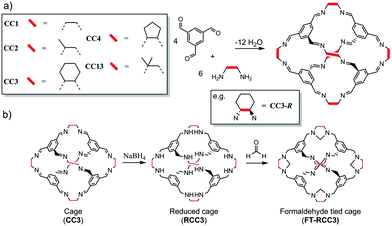 | ||
| Scheme 1 (a) Shape persistent chiral [4 + 6] imine cages CC1–CC4, and CC13. (b) Transformation of imine cage (CC3) to formaldehyde tied cage (FT-RCC3). | ||
The organic cages are formed by reacting 1,3,5-triformylbenzene with different vicinal diamines (Scheme 1a).4,32,34 For CC2, CC3 and CC4, the chirality of the diamine controls the helical chirality of the cage molecule, whereas CC1 and CC13 are synthesised using achiral diamines and prepared as helical racemates. For this series of POCs, the intrinsic cage cavity is accessible via four chiral triangular windows through which guest diffusion can occur. Subtle differences in the size and shape of the vicinal diamines (vertex groups) has a profound effect on how the cages crystallise as porous solids. For example, CC3, which has cyclohexyl vertex groups, typically packs window-to-window (Fig. 1a) and crystallises as a microporous porous solid with an interconnected diamondoid pore channel (CC3α, Fig. 1b). Cages CC1, CC2-R, CC4-R, and CC13, which all have similar shaped cores and window dimensions, all pack differently without the use of directing solvents. This is important because the crystal packing of the cages has profound effect on the physical properties. For example, the cavities of all the [4 + 6] cages (Scheme 1) are a near perfect fit for Xe. However, a comparison of the most commonly observed crystal packings for these cages revealed that only CC3-R crystallised to form a porous solid, CC3α, that has additional extrinsic adsorption sites, which are located between the cage windows and are well-matched in size to Xe. This allows CC3α to favourably adsorb Xe/Kr with high selectivity and separate Xe from Xe![[thin space (1/6-em)]](https://www.rsc.org/images/entities/char_2009.gif) :
:![[thin space (1/6-em)]](https://www.rsc.org/images/entities/char_2009.gif) Kr gas mixtures.12 We have also shown that CC3α can be used to separate xylene mixtures,35 enantiomers,12 and hexane isomers.36 Hence, targeting a series of crystalline phases with this diamondoid pore topology could be advantageous and enable the physical properties of CC3α to be varied systematically, as for isoreticular MOFs. Previously, we showed that different cage molecules can be crystallized together to form a single homogeneous structure27 and that the synthesis of cage–cage co-crystals has tremendous advantages: for example, by providing access to stable crystalline forms.37 We therefore decided to investigate the crystal packing of two recently discovered cages, FT-RCC3 (ref. 38) and CC13.32 As individual components, FT-RCC3 and CC13 have interesting properties in comparison to our other [4 + 6] cages. For example, FT-RCC3 is much more stable in acidic and basic solution than CC3,38 and the dimethyl vertices of CC13 can frustrate the packing of this cage, greatly increasing extrinsic porosity in the crystal structure.32 Investigating the generality of co-crystal formation with these cages was therefore a desirable target.
Kr gas mixtures.12 We have also shown that CC3α can be used to separate xylene mixtures,35 enantiomers,12 and hexane isomers.36 Hence, targeting a series of crystalline phases with this diamondoid pore topology could be advantageous and enable the physical properties of CC3α to be varied systematically, as for isoreticular MOFs. Previously, we showed that different cage molecules can be crystallized together to form a single homogeneous structure27 and that the synthesis of cage–cage co-crystals has tremendous advantages: for example, by providing access to stable crystalline forms.37 We therefore decided to investigate the crystal packing of two recently discovered cages, FT-RCC3 (ref. 38) and CC13.32 As individual components, FT-RCC3 and CC13 have interesting properties in comparison to our other [4 + 6] cages. For example, FT-RCC3 is much more stable in acidic and basic solution than CC3,38 and the dimethyl vertices of CC13 can frustrate the packing of this cage, greatly increasing extrinsic porosity in the crystal structure.32 Investigating the generality of co-crystal formation with these cages was therefore a desirable target.
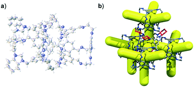
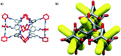 | ||
| Fig. 1 POC CC3 packs window-to-window (a) to form a crystalline microporous solid, referred to as CC3α, that has a diamondoid shaped pore topology (b). | ||
Experimental
Synthetic procedures
1,3,5-Triformylbenzene was purchased from Manchester Organics, UK. All other chemicals were purchased from Sigma-Aldrich and used as received. The cage molecules CC1,4CC2,4CC3,31CC4,34CC13,32 and FT-RCC3 (ref. 38) were synthesised as previously reported. Cage chirality was determined from the synthetic procedures only.Materials and methods
![[thin space (1/6-em)]](https://www.rsc.org/images/entities/char_2009.gif) :
:![[thin space (1/6-em)]](https://www.rsc.org/images/entities/char_2009.gif) 0.375
0.375![[thin space (1/6-em)]](https://www.rsc.org/images/entities/char_2009.gif) :
:![[thin space (1/6-em)]](https://www.rsc.org/images/entities/char_2009.gif) 0.25 molar ratio in glass sample vials and vapour diffusion of acetone was carried out for five days. Crystals were collected by filtration and dried under vacuum at 90 °C.
0.25 molar ratio in glass sample vials and vapour diffusion of acetone was carried out for five days. Crystals were collected by filtration and dried under vacuum at 90 °C.
![[thin space (1/6-em)]](https://www.rsc.org/images/entities/char_2009.gif) 861(5) Å3; ρ = 0.897 g cm−3; μ(Mo-Kα) = 0.054 mm−3; F(000) = 4320; crystal size = 0.17 × 0.15 × 0.09 mm; T = 400(2) K; 26
861(5) Å3; ρ = 0.897 g cm−3; μ(Mo-Kα) = 0.054 mm−3; F(000) = 4320; crystal size = 0.17 × 0.15 × 0.09 mm; T = 400(2) K; 26![[thin space (1/6-em)]](https://www.rsc.org/images/entities/char_2009.gif) 336 reflections measured (2.343 < θ < 20.790°), 1321 unique (Rint = 0.0372), 971 I > 2σ(I); R1 = 0.0491 for the observed and R1 = 0.0708 for all reflections; wR2 = 0.1655 for all reflections; max/min residual electron density = 0.119 and −0.064 e Å−3; data/restraints/parameters = 1321/67/114; GOF = 1.059.
336 reflections measured (2.343 < θ < 20.790°), 1321 unique (Rint = 0.0372), 971 I > 2σ(I); R1 = 0.0491 for the observed and R1 = 0.0708 for all reflections; wR2 = 0.1655 for all reflections; max/min residual electron density = 0.119 and −0.064 e Å−3; data/restraints/parameters = 1321/67/114; GOF = 1.059.
A single crystal of (CC3-S0.5CC4-S0.5)·(CC13-S0.5CC3-S0.25CC4-S0.25) was mounted on MiTeGen gripper and initially heated to 425 K before a data set was recorded at 100 K. Crystal data for (CC3-S0.5CC4-S0.5)·(CC13-S0.5CC3-S0.25CC4-S0.25); CCDC # 1546305. Formula = C133.50H176.84N24O11.92; M = 2308.50 g mol−1; cubic space group F23, colourless prism shape crystal; a = 24.1722(10) Å; V = 14123.7(18) Å3; ρ = 1.086 g cm−3; μ(λ = 0.7749 Å) = 0.085 mm−3; F(000) = 4965; crystal size = 0.2 × 0.19 × 0.15 mm; T = 100(2) K; 32![[thin space (1/6-em)]](https://www.rsc.org/images/entities/char_2009.gif) 931 reflections measured (2.598 < θ < 28.180°), 2259 unique (Rint = 0.0510), 2031 I > 2σ(I); R1 = 0.0941 for the observed and R1 = 0.1038 for all reflections; wR2 = 0.2252 for all reflections; max/min residual electron density = 0.547 and −0.395 e Å−3; data/restraints/parameters = 2259/42/203; GOF = 2.259. Due to disorder, during the refinement of (CC3-S0.5CC4-S0.5)·(CC13-S0.5CC3-S0.25CC4-S0.25), methyl group C atoms were refined isotropically without riding H atoms.
931 reflections measured (2.598 < θ < 28.180°), 2259 unique (Rint = 0.0510), 2031 I > 2σ(I); R1 = 0.0941 for the observed and R1 = 0.1038 for all reflections; wR2 = 0.2252 for all reflections; max/min residual electron density = 0.547 and −0.395 e Å−3; data/restraints/parameters = 2259/42/203; GOF = 2.259. Due to disorder, during the refinement of (CC3-S0.5CC4-S0.5)·(CC13-S0.5CC3-S0.25CC4-S0.25), methyl group C atoms were refined isotropically without riding H atoms.
Results and discussion
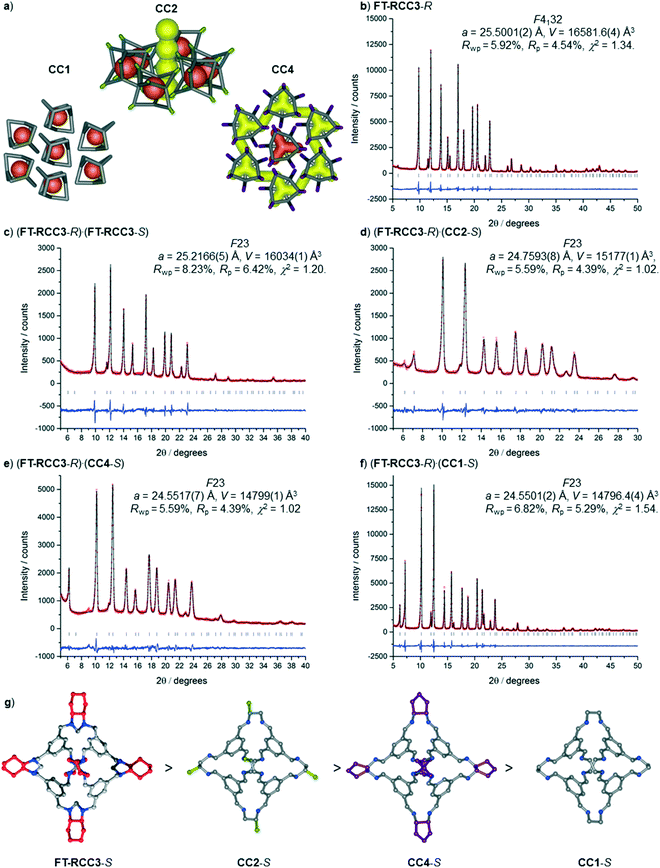
We have recently shown that CC3 can be chemically reduced to afford RCC3 (Scheme 1b) and that the flexible diamine groups in RCC3 can be further reacted with formaldehyde to afford the rigid ‘tied’ cage, FT-RCC3 (Scheme 1b).38In its native, chirally-pure form, FT-RCC3, like the parent cage CC3, crystallises in the cubic space group F4132. The cage molecules pack window-to-window, resulting in the formation of a diamondoid shaped pore that runs through the cage cavities. However, the replacement of imine groups in CC3 with aminal groups in FT-RCC3 changes the shape of the cage (Fig. 2). From the reported single crystal structures of CC3 (Fig. 2b),4 and FT-RCC3 (Fig. 2c),38 there is a clear difference in the distance between the centre of the aromatic rings in the cage core; 6.9 Å in CC3versus 8.3 Å in FT-RCC3. Thus, the geometry of the windows is different and the size of the tetrahedron in FT-RCC3 is 36% larger than in CC3. Since the cages pack isostructurally, this results in FT-RCC3 (a = 25.4857(6) Å) having a larger unit cell edge than CC3α (a = 25.016(2) Å) from Le Bail fitted PXRD data.38 To investigate what effect this might have on the crystallisation properties of FT-RCC3 in comparison to CC3, we initially co-crystallised FT-RCC3-R with racemic CC1 by combining equal volumes of 4.47 mM stock solutions of FT-RCC3-R and CC1 in CH2Cl2. Vapour diffusion of acetone into the CH2Cl2 solution resulted in the formation of a new quasiracemate, (FT-RCC3-R)·(CC1-S), which crystallised in the cubic space group F23 as octahedral shaped blocks (Fig. S1†). Although CC1 is helically chiral, it can readily switch between chiral forms in solution and the solid state.45,46 Only the comparable -S form of CC1 is found in the crystal structure. We previously observed this behaviour when co-crystallising CC1 with CC3-R, whereby preferential heterochiral window-to-window interactions between cage molecules can be energetically more favourable that the comparable homochiral window-to-window interactions. Hence, formation of a racemate or quasiracemate is energetically preferred.27 This approach is also transferable to macrocycles prepared using chirally pure trans-1,2-diaminocyclohexane,47,48 and trigonal prismatic cages with comparable window dimension to that of CC3.28 As a result of energetically favourable window-to-window interactions, CC1 self-sorts during crystallisation to enable the exclusive formation of, (FT-RCC3-R)·(CC1-S) (Fig. 3). The structure, which crystallised as a solvate, is stable to thermal desolvation of the pores at 400 K, observed while desolvating a single crystal prior to collecting X-ray diffraction data. In the desolvated structure (Fig. 3a) window-to-window packing results in the formation of an interconnected diamondoid pore (Fig. 3b). For further analysis, bulk material was activated by heating crystalline material, collected by filtration, to 90 °C under dynamic vacuum for 12 hours (Fig. 4). TGA also shows that the material is stable to 350 °C (Fig. S2†). It should be noted that for CC3, favourable heterochiral window-to-window interactions enables the cages to pack closer together. As a result, the cell parameters determined for racemic CC3 (ref. 27) (a = 24.639(1) Å) are shorter than those determined for chiral CC3 (a = 25.016(2) Å). Hence, it is possible to determine the likelihood of two cage molecules crystallising together based upon a shift in the unit cell parameters.
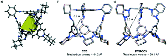 | ||
| Fig. 2 (a) Structure of [4 + 6] cage molecule highlighting tetrahedral geometry between aromatic groups. From the reported single crystal structures of CC3 (ref. 4) (b) and FT-RCC3 (ref. 38) (c) there is a clear difference in the shape and size of the tetrahedral core, resulting in changes to the shape and size of the cage windows. R handed cages are shown. | ||
To further explore the generality of our approach, equal volumetric quantities of 4.47 mM solutions of FT-RCC3-R with CC2-S, CC4-S, or FT-RCC3-S in CH2Cl2 were combined. Vapour diffusion of acetone into the CH2Cl2 solution resulted in the formation of crystalline powders that we analysed by PXRD. Analysis of the crystallisation screen was carried out by Le Bail fitting the activate PXRD data that was collected at room temperature (Fig. 5).
Analysis of the unit cell parameters determined for the structures revealed a decrease in the unit cell volume along the series FT-RCC3-R > (FT-RCC3-R)·(FT-RCC3-S) > (FT-RCC3-R)·(CC2-S) > (FT-RCC3-R)·(CC4-S) > (FT-RCC3-R)·(CC1-S) (Fig. 5). Importantly, for CC1, CC2-S, and CC4-S, this also resulted in a change from their typical crystal packing modes (Fig. 5a) when these cages were co-crystallised with FT-RCC3-R.
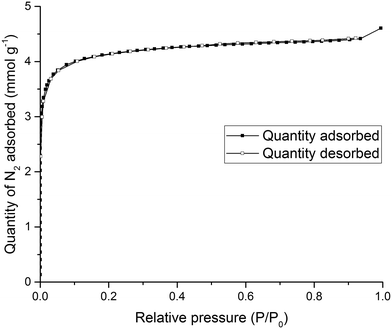
To test the solid state porosity of the quasiracemate, (FT-RCC3-R)·(CC1-S), a sample was activated and gas sorption analysis was carried out. (FT-RCC3-R)·(CC1-S) has a type I N2 sorption isotherm at 77.3 K with a sharp low pressure step indicative of a microporous material (Fig. 6). (FT-RCC3-R)·(CC1-S) adsorbs 4.60 mmol g−1 of N2 at 77.3 K and 1 bar (Fig. 6), and has a calculated apparent Brunauer–Emmett–Teller surface area (SABET) of 314 m2 g−1. (FT-RCC3-R)·(CC1-S) is also porous to H2, CO2, and CH4. The material adsorbs 5.23 mmol g−1 of H2 at 77 K and 1 bar (Fig. S3a†), 1.9 mmol g−1 of CO2 at 278 K and 1 bar (Fig. S3b†), and 1.4 mmol g−1 of CH4 at 278 K 1 bar (Fig. S3c†). Importantly, the PXRD of (FT-RCC3-R)·(CC1-S) did not change during the gas sorption experiments highlighting that the material did not transform phase during activation and sorption isotherms (Fig. S4†).
It was not possible to isolate a single crystal structure of the quasiracemate, (FT-RCC3-R)·(CC13-S), by using comparable crystallisation conditions to those successful for (FT-RCC3-R)·(CC1-S). Instead, SC-XRD and PXRD data indicated formation of single component crystals of FT-RCC3-R, mixed with poorly crystalline CC13, when crystallised from CH2Cl2/acetone (Fig. S5†). This again highlights the lack of complete generality in designing molecular crystals ‘intuitively’ when considering the relatively small difference in structure between CC13 and CC2 or CC4. However, the rational formation of three stable quasiracemate phases in a predictable manner is a further step forward in terms of porous molecular cocrystal design.
Ternary co-crystal
By increasing the number of cage components, a greater number of potential crystallization outcomes are possible. We showed previously that is was possible to form a ternary window-to-window co-crystal comprising the POCs CC1, CC3-R, and CC4-R,49 with the general formula, (CC3-RxCC4-Ry)·(CC1-S) (where x + y = 1). In the ternary co-crystal, CC4-R and CC3-R were disordered over one cage position, as a result, the composition of the ternary co-crystal, and the solid state porosity, could be fine-tuned by varying the molar ratio of CC3-R![[thin space (1/6-em)]](https://www.rsc.org/images/entities/char_2009.gif) :
:![[thin space (1/6-em)]](https://www.rsc.org/images/entities/char_2009.gif) CC4-R used during crystllisation.49 To investigate whether CC13 could also be used to form a ternary co-crystal, we employed the organic cage CC3, instead of FT-RCC3, because CC3 and CC13 are known to cocrystallise.50 By forming an isoreticular ternary co-crystal, it might follow that a quaternary co-crystal could also be formed, whereby the molar ratio of the cages CC1 and CC13 is varied. We therefore initially attempted the ternary co-crystallisation of CC13 with CC3-S and CC4-S. Initially, 1
CC4-R used during crystllisation.49 To investigate whether CC13 could also be used to form a ternary co-crystal, we employed the organic cage CC3, instead of FT-RCC3, because CC3 and CC13 are known to cocrystallise.50 By forming an isoreticular ternary co-crystal, it might follow that a quaternary co-crystal could also be formed, whereby the molar ratio of the cages CC1 and CC13 is varied. We therefore initially attempted the ternary co-crystallisation of CC13 with CC3-S and CC4-S. Initially, 1![[thin space (1/6-em)]](https://www.rsc.org/images/entities/char_2009.gif) :
:![[thin space (1/6-em)]](https://www.rsc.org/images/entities/char_2009.gif) 0.5
0.5![[thin space (1/6-em)]](https://www.rsc.org/images/entities/char_2009.gif) :
:![[thin space (1/6-em)]](https://www.rsc.org/images/entities/char_2009.gif) 0.5 volumetric ratios of 4.47 mM stock solutions of CC13
0.5 volumetric ratios of 4.47 mM stock solutions of CC13![[thin space (1/6-em)]](https://www.rsc.org/images/entities/char_2009.gif) :
:![[thin space (1/6-em)]](https://www.rsc.org/images/entities/char_2009.gif) CC3-S
CC3-S![[thin space (1/6-em)]](https://www.rsc.org/images/entities/char_2009.gif) :
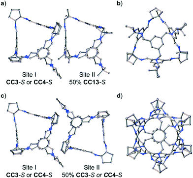
:![[thin space (1/6-em)]](https://www.rsc.org/images/entities/char_2009.gif) CC4-S, dissolved in CH2Cl2, were combined. These ratios were chosen to allow an isostructural ternary co-crystal to be formed. However, slow vapour diffusion of acetone resulted in the formation of prism shaped crystals (Fig. S6†) that were characterised by SC-XRD using synchrotron radiation as, (CC3-S0.5CC4-S0.5)·(CC13-S0.5CC3-S0.25CC4-S0.25) (Fig. S7†). This structure, which crystallised in the cubic space group F23, has a different cage composition, and crystal structure, to our previously reported ternary co-crystal.49 Analysis of the structure of the new ternary co-crystal revealed the difference between these phases. In (CC3-S0.5CC4-S0.5)·(CC13-S0.5CC3-S0.25CC4-S0.25), CC3-S and CC4-S co-crystallise with only the comparable -S hand of CC13. In addition, the packing of cages is not exclusively window-to-window. In the crystal structure, there are two sites: (CC3-S0.5CC4-S0.5) (site I); and (CC13-S0.5CC3-S0.25CC4-S0.25) (site II) (Fig. 7). Site I is shared between CC3-S and CC4-S with an approximate 0.5
CC4-S, dissolved in CH2Cl2, were combined. These ratios were chosen to allow an isostructural ternary co-crystal to be formed. However, slow vapour diffusion of acetone resulted in the formation of prism shaped crystals (Fig. S6†) that were characterised by SC-XRD using synchrotron radiation as, (CC3-S0.5CC4-S0.5)·(CC13-S0.5CC3-S0.25CC4-S0.25) (Fig. S7†). This structure, which crystallised in the cubic space group F23, has a different cage composition, and crystal structure, to our previously reported ternary co-crystal.49 Analysis of the structure of the new ternary co-crystal revealed the difference between these phases. In (CC3-S0.5CC4-S0.5)·(CC13-S0.5CC3-S0.25CC4-S0.25), CC3-S and CC4-S co-crystallise with only the comparable -S hand of CC13. In addition, the packing of cages is not exclusively window-to-window. In the crystal structure, there are two sites: (CC3-S0.5CC4-S0.5) (site I); and (CC13-S0.5CC3-S0.25CC4-S0.25) (site II) (Fig. 7). Site I is shared between CC3-S and CC4-S with an approximate 0.5![[thin space (1/6-em)]](https://www.rsc.org/images/entities/char_2009.gif) :
:![[thin space (1/6-em)]](https://www.rsc.org/images/entities/char_2009.gif) 0.5 molar ratio. These cages are superimposed except for the aliphatic rings on the cages vertices, which are chemically different; cyclohexyl rings for CC3-S versus cyclopentyl rings for CC4-S.Site II is shared between CC13-S, CC3-S, and CC4-S with an approximate 0.5
0.5 molar ratio. These cages are superimposed except for the aliphatic rings on the cages vertices, which are chemically different; cyclohexyl rings for CC3-S versus cyclopentyl rings for CC4-S.Site II is shared between CC13-S, CC3-S, and CC4-S with an approximate 0.5![[thin space (1/6-em)]](https://www.rsc.org/images/entities/char_2009.gif) :
:![[thin space (1/6-em)]](https://www.rsc.org/images/entities/char_2009.gif) 0.25
0.25![[thin space (1/6-em)]](https://www.rsc.org/images/entities/char_2009.gif) :
:![[thin space (1/6-em)]](https://www.rsc.org/images/entities/char_2009.gif) 0.25 molar ratio split. The -S handed form of CC13, that occupies 50% of site II, is packed window-to-arene with the CC3-S and CC4-S molecules positioned on site I (Fig. 7a and b). The other 50% of site II is occupied by CC3-S or CC4-S and these cages pack window-to-window with the site I positioned CC3-S and CC4-S. Hence, 50% of the crystal structure is window-to-arene packed CC13-S with CC3-S or CC4-S. The other 50% of the crystal structure is window-to-window packed CC3-S or CC4-S (Fig. 7c and d).
0.25 molar ratio split. The -S handed form of CC13, that occupies 50% of site II, is packed window-to-arene with the CC3-S and CC4-S molecules positioned on site I (Fig. 7a and b). The other 50% of site II is occupied by CC3-S or CC4-S and these cages pack window-to-window with the site I positioned CC3-S and CC4-S. Hence, 50% of the crystal structure is window-to-arene packed CC13-S with CC3-S or CC4-S. The other 50% of the crystal structure is window-to-window packed CC3-S or CC4-S (Fig. 7c and d).
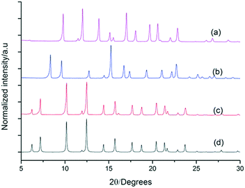
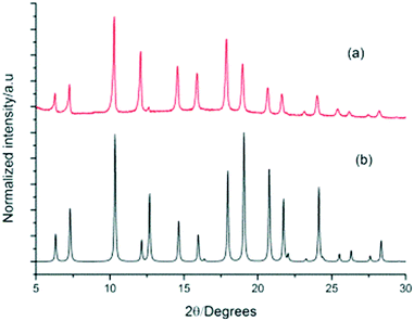
To evaluate the phase purity and stability of this new ternary co-crystal, which is only the second example reported for POCs, crystals were collected by filtration and characterised by PXRD (Fig. 8). A single phase was determined by PXRD that matches the simulated PXRD pattern of (CC3-S0.5CC4-S0.5)·(CC13-S0.5CC3-S0.25CC4-S0.25). TGA also showed that this material was stable up to 375 °C (Fig. S8†).
Due to disorder in the crystal structure, we also carried out qualitative and quantitative HPLC analysis to confirm the exact composition of the ternary co-crystal. The cages have different retention times: CC3 (7.52 min), CC4 (6.97 min), CC13 (4.2 min) (Fig. S9†). Hence, it was possible to accurately determine the cage composition of the disordered ternary co-crystal. To confirm the composition of the new ternary co-crystal before carrying further analysis, a 0.375![[thin space (1/6-em)]](https://www.rsc.org/images/entities/char_2009.gif) :
:![[thin space (1/6-em)]](https://www.rsc.org/images/entities/char_2009.gif) 0.375
0.375![[thin space (1/6-em)]](https://www.rsc.org/images/entities/char_2009.gif) :
:![[thin space (1/6-em)]](https://www.rsc.org/images/entities/char_2009.gif) 0.25 molar ratio of CC3-S
0.25 molar ratio of CC3-S![[thin space (1/6-em)]](https://www.rsc.org/images/entities/char_2009.gif) :
:![[thin space (1/6-em)]](https://www.rsc.org/images/entities/char_2009.gif) CC4-S
CC4-S![[thin space (1/6-em)]](https://www.rsc.org/images/entities/char_2009.gif) :
:![[thin space (1/6-em)]](https://www.rsc.org/images/entities/char_2009.gif) CC13, dissolved in CH2Cl2, was combined and crystallised by slow vapour diffusion of acetone. Single crystals were selected using a microscope and dissolved in CH2Cl2. HPLC analysis displayed three peaks with retention times of 4.22 min, 6.99 min, and 7.61 min (Fig. S10†). Quantitative analysis of ten different ternary cage co-crystals confirmed the average 0.375
CC13, dissolved in CH2Cl2, was combined and crystallised by slow vapour diffusion of acetone. Single crystals were selected using a microscope and dissolved in CH2Cl2. HPLC analysis displayed three peaks with retention times of 4.22 min, 6.99 min, and 7.61 min (Fig. S10†). Quantitative analysis of ten different ternary cage co-crystals confirmed the average 0.375![[thin space (1/6-em)]](https://www.rsc.org/images/entities/char_2009.gif) :
:![[thin space (1/6-em)]](https://www.rsc.org/images/entities/char_2009.gif) 0.375
0.375![[thin space (1/6-em)]](https://www.rsc.org/images/entities/char_2009.gif) :
:![[thin space (1/6-em)]](https://www.rsc.org/images/entities/char_2009.gif) 0.25 molar ratio between CC4-S
0.25 molar ratio between CC4-S![[thin space (1/6-em)]](https://www.rsc.org/images/entities/char_2009.gif) :
:![[thin space (1/6-em)]](https://www.rsc.org/images/entities/char_2009.gif) CC3-S
CC3-S![[thin space (1/6-em)]](https://www.rsc.org/images/entities/char_2009.gif) :
:![[thin space (1/6-em)]](https://www.rsc.org/images/entities/char_2009.gif) CC13, in good agreement with the refined crystal structure.
CC13, in good agreement with the refined crystal structure.
To test the porosity of the ternary co-crystal, (CC3-S0.5CC4-S0.5)·(CC13-S0.5CC3-S0.25CC4-S0.25) was activated by heating a sample at 90 °C under dynamic vacuum. (CC3-S0.5CC4-S0.5)·(CC13-S0.5CC3-S0.25CC4-S0.25) has a type I N2 sorption isotherm at 77.3 K with a sharp low pressure step (Fig. 9). (CC3-S0.5CC4-S0.5)·(CC13-S0.5CC3-S0.25CC4-S0.25) adsorbs 7.51 mmol g−1 of N2 at 1 bar and 77.3 K.
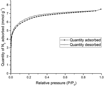 | ||
| Fig. 9 Type I N2 gas sorption isotherms for (CC3-S0.5CC4-S0.5)·(CC13-S0.5CC3-S0.25CC4-S0.25) recorded at 77.3 K. | ||
Importantly, the PXRD pattern of (CC3-S0.5CC4-S0.5)·(CC13-S0.5CC3-S0.25CC4-S0.25) did not change during sorption analysis indicating that this novel ternary POC co-crystal material was stable during gas sorption analysis (Fig. S12†). (CC3-S0.5CC4-S0.5)·(CC13-S0.5CC3-S0.25CC4-S0.25) is also porous to Xe and Kr (Fig. S13†). This indicates that, despite the window-to-arene packing, diffusion of these guests is cooperative. Thus, the material is porous to these gasses even though the window-to-arene packing in 50% of the crystal structure might have resulted in the porosity being ‘turned off’.
Conclusions
We have synthesized a family of isoreticular quasiracemates, (FT-RCC3-R)·(CCX-S) (where X = 1, 2, or 4), without the use of strong directional intermolecular bonding interactions. Co-crystallisation is a result of a combination of multiple weak interactions between opposite handed cages. Our results also show that a subtle change in the vertex functionality can increase the number of potential outcomes for the co-crystallisation. This strategy enabled the preparation of a rare ternary co-crystal, (CC3-S0.5CC4-S0.5)·(CC13-S0.5CC3-S0.25CC4-S0.25).Acknowledgements
We thank Rob C. for assistance with gas sorption measurements. We acknowledge the Engineering and Physical Sciences Research Council (EP/N004884/1) and European Research Council under the European Union's Seventh Framework Programme (FP/2007-2013) through grant agreement numbers 321156 (ERC-AG-PE5-ROBOT) for funding. T. H. thanks the Royal Society for a University Research Fellowship. We thank the Advanced Light Source, supported by the Director, Office of Science, Office of Basic Energy Sciences, of the US Department of Energy under contract number DE-AC02-05CH11231, and S. J. Teat and K. J. Gagnon for their assistance.Notes and references
- T. Hasell and A. I. Cooper, Nat. Rev. Mater., 2016, 1, 16053 CrossRef CAS.
- N. Giri, M. G. Del Pópolo, G. Melaugh, R. L. Greenaway, K. Rätzke, T. Koschine, L. Pison, M. F. C. Gomes, A. I. Cooper and S. L. James, Nature, 2015, 527, 216–220 CrossRef CAS PubMed.
- G. Zhang and M. Mastalerz, Chem. Soc. Rev., 2014, 43, 1934–1947 RSC.
- T. Tozawa, J. T. A. Jones, S. I. Swamy, S. Jiang, D. J. Adams, S. Shakespeare, R. Clowes, D. Bradshaw, T. Hasell, S. Y. Chong, C. Tang, S. Thompson, J. Parker, A. Trewin, J. Bacsa, A. M. Z. Slawin, A. Steiner and A. I. Cooper, Nat. Mater., 2009, 8, 973–978 CrossRef CAS PubMed.
- M. Mastalerz, M. W. Schneider, I. M. Oppel and O. Presly, Angew. Chem., Int. Ed., 2011, 50, 1046–1051 CrossRef CAS PubMed.
- Y. Jin, B. A. Voss, R. D. Noble and W. Zhang, Angew. Chem., Int. Ed., 2010, 49, 6348–6351 CrossRef CAS PubMed.
- S. M. Elbert, F. Rominger and M. Mastalerz, Chem. – Eur. J., 2014, 20, 16707–16720 CrossRef CAS PubMed.
- M. W. Schneider, H. J. S. Hauswald, R. Stoll and M. Mastalerz, Chem. Commun., 2012, 48, 9861–9863 RSC.
- G. Zhang, O. Presly, F. White, I. M. Oppel and M. Mastalerz, Angew. Chem., Int. Ed., 2014, 53, 5126–5130 CAS.
- G. Zhang, O. Presly, F. White, I. M. Oppel and M. Mastalerz, Angew. Chem., Int. Ed., 2014, 53, 1516–1520 CrossRef CAS PubMed.
- A. Avellaneda, P. Valente, A. Burgun, J. D. Evans, A. W. Markwell-Heys, D. Rankine, D. J. Nielsen, M. R. Hill, C. J. Sumby and C. J. Doonan, Angew. Chem., Int. Ed., 2013, 52, 3746–3749 CrossRef CAS PubMed.
- L. Chen, P. S. Reiss, S. Y. Chong, D. Holden, K. E. Jelfs, T. Hasell, M. A. Little, A. Kewley, M. E. Briggs, A. Stephenson, K. M. Thomas, J. A. Armstrong, J. Bell, J. Busto, R. Noel, J. Liu, D. M. Strachan, P. K. Thallapally and A. I. Cooper, Nat. Mater., 2014, 13, 954–960 CrossRef CAS PubMed.
- T. Hasell, M. Miklitz, A. Stephenson, M. A. Little, S. Y. Chong, R. Clowes, L. Chen, D. Holden, G. A. Tribello, K. E. Jelfs and A. I. Cooper, J. Am. Chem. Soc., 2016, 138, 1653–1659 CrossRef CAS PubMed.
- S.-M. Xie and L.-M. Yuan, J. Sep. Sci., 2017, 40, 124–137 CrossRef CAS PubMed.
- R. McCaffrey, H. Long, Y. Jin, A. Sanders, W. Park and W. Zhang, J. Am. Chem. Soc., 2014, 136, 1782–1785 CrossRef CAS PubMed.
- B. Mondal, K. Acharyya, P. Howlader and P. S. Mukherjee, J. Am. Chem. Soc., 2016, 138, 1709–1716 CrossRef CAS PubMed.
- M. Liu, L. Chen, S. Lewis, S. Y. Chong, M. A. Little, T. Hasell, I. M. Aldous, C. M. Brown, M. W. Smith, C. A. Morrison, L. J. Hardwick and A. I. Cooper, Nat. Commun., 2016, 7, 12750 CrossRef CAS PubMed.
- G. R. Desiraju, Angew. Chem., Int. Ed., 2014, 53, 1516–1520 ( Angew. Chem., Int. Ed. Engl. , 1995 , 34 , 2311–2327 ) CrossRef PubMed.
- C. B. Aakeroy and D. J. Salmon, CrystEngComm, 2005, 7, 439–448 RSC.
- S. Tothadi and G. R. Desiraju, Chem. Commun., 2013, 49, 7791–7793 RSC.
- F. Topić and K. Rissanen, J. Am. Chem. Soc., 2016, 138, 6610–6616 CrossRef PubMed.
- A. S. Sinha and C. B. Aakeröy, in Reference Module in Chemistry, Molecular Sciences and Chemical Engineering, Elsevier, 2016, DOI:10.1016/B978-0-12-409547-2.13696-0.
- S. Tothadi, P. Sanphui and G. R. Desiraju, Cryst. Growth Des., 2014, 14, 5293–5302 CAS.
- H. Deng, C. J. Doonan, H. Furukawa, R. B. Ferreira, J. Towne, C. B. Knobler, B. Wang and O. M. Yaghi, Science, 2010, 327, 846–850 CrossRef CAS PubMed.
- H. Furukawa, K. E. Cordova, M. O’Keeffe and O. M. Yaghi, Science, 2013, 341, 1230444 CrossRef PubMed.
- D. A. Gomez-Gualdron, Y. J. Colon, X. Zhang, T. C. Wang, Y.-S. Chen, J. T. Hupp, T. Yildirim, O. K. Farha, J. Zhang and R. Q. Snurr, Energy Environ. Sci., 2016, 9, 3279–3289 CAS.
- J. T. A. Jones, T. Hasell, X. Wu, J. Bacsa, K. E. Jelfs, M. Schmidtmann, S. Y. Chong, D. J. Adams, A. Trewin, F. Schiffman, F. Cora, B. Slater, A. Steiner, G. M. Day and A. I. Cooper, Nature, 2011, 474, 367–371 CrossRef CAS PubMed.
- A. G. Slater, M. A. Little, A. Pulido, S. Y. Chong, D. Holden, L. Chen, C. Morgan, X. Wu, G. Cheng, R. Clowes, M. E. Briggs, T. Hasell, K. E. Jelfs, G. M. Day and A. I. Cooper, Nat. Chem., 2017, 9, 17–25 CAS.
- E. O. Pyzer-Knapp, H. P. G. Thompson, F. Schiffmann, K. E. Jelfs, A. I. Cooper and G. M. Day, Chem. Sci., 2014, 5, 2235–2245 RSC.
- A. Pulido, L. Chen, T. Kaczorowski, D. Holden, M. A. Little, S. Y. Chong, B. J. Slater, D. P. McMahon, B. Bonillo, C. J. Stackhouse, A. Stephenson, C. M. Kane, R. Clowes, T. Hasell, A. I. Cooper and G. M. Day, Nature, 2017, 543, 657–664 CrossRef CAS PubMed.
- T. Hasell, S. Y. Chong, K. E. Jelfs, D. J. Adams and A. I. Cooper, J. Am. Chem. Soc., 2012, 134, 588–598 CrossRef CAS PubMed.
- T. Hasell, J. L. Culshaw, S. Y. Chong, M. Schmidtmann, M. A. Little, K. E. Jelfs, E. O. Pyzer-Knapp, H. Shepherd, D. J. Adams, G. M. Day and A. I. Cooper, J. Am. Chem. Soc., 2014, 136, 1438–1448 CrossRef CAS PubMed.
- M. A. Little, S. Y. Chong, M. Schmidtmann, T. Hasell and A. I. Cooper, Chem. Commun., 2014, 50, 9465–9468 RSC.
- T. Mitra, X. Wu, R. Clowes, J. T. A. Jones, K. E. Jelfs, D. J. Adams, A. Trewin, J. Bacsa, A. Steiner and A. I. Cooper, Chem. – Eur. J., 2011, 17, 10235–10240 CrossRef CAS PubMed.
- T. Mitra, K. E. Jelfs, M. Schmidtmann, A. Ahmed, S. Y. Chong, D. J. Adams and A. I. Cooper, Nat. Chem., 2013, 5, 276–281 CrossRef CAS PubMed.
- A. Kewley, A. Stephenson, L. Chen, M. E. Briggs, T. Hasell and A. I. Cooper, Chem. Mater., 2015, 27, 3207–3210 CrossRef CAS.
- M. A. Little, M. E. Briggs, T. A. JonesJames, M. Schmidtmann, T. Hasell, S. Y. Chong, K. E. Jelfs, L. Chen and A. I. Cooper, Nat. Chem., 2015, 7, 153–159 CrossRef CAS PubMed.
- M. Liu, M. A. Little, K. E. Jelfs, J. T. A. Jones, M. Schmidtmann, S. Y. Chong, T. Hasell and A. I. Cooper, J. Am. Chem. Soc., 2014, 136, 7583–7586 CrossRef CAS PubMed.
- G. M. Sheldrick, SADABS, University of Göttingen, Germany, 2008 Search PubMed.
- G. M. Sheldrick, Acta Crystallogr., Sect. A: Found. Adv., 2015, 71, 3–8 CrossRef PubMed.
- G. M. Sheldrick, Acta Crystallogr., Sect. A: Found. Crystallogr., 2008, 64, 112–122 CrossRef CAS PubMed.
- G. Sheldrick, Acta Crystallogr., Sect. C: Struct. Chem., 2015, 71, 3–8 CrossRef PubMed.
- O. V. Dolomanov, L. J. Bourhis, R. J. Gildea, J. A. K. Howard and H. Puschmann, J. Appl. Crystallogr., 2009, 42, 339–341 CrossRef CAS.
- TOPAS-Academic v. 5 Coelho Software, Brisbane, Australia, 2012 Search PubMed.
- K. E. Jelfs, F. Schiffmann, J. T. A. Jones, B. Slater, F. Cora and A. I. Cooper, Phys. Chem. Chem. Phys., 2011, 13, 20081–20085 RSC.
- J. T. A. Jones, D. Holden, T. Mitra, T. Hasell, D. J. Adams, K. E. Jelfs, A. Trewin, D. J. Willock, G. M. Day, J. Bacsa, A. Steiner and A. I. Cooper, Angew. Chem., Int. Ed., 2011, 50, 749–753 CrossRef CAS PubMed.
- Z. Liu, J. Sun, Y. Zhou, Y. Zhang, Y. Wu, S. K. M. Nalluri, Y. Wang, A. Samanta, C. A. Mirkin, G. C. Schatz and J. F. Stoddart, J. Org. Chem., 2016, 81, 2581–2588 CrossRef CAS PubMed.
- Y. Wu, S. K. M. Nalluri, R. M. Young, M. D. Krzyaniak, E. A. Margulies, J. F. Stoddart and M. R. Wasielewski, Angew. Chem., Int. Ed., 2015, 54, 11971–11977 CrossRef CAS PubMed.
- T. Hasell, S. Y. Chong, M. Schmidtmann, D. J. Adams and A. I. Cooper, Angew. Chem., Int. Ed., 2012, 51, 7154–7157 CrossRef CAS PubMed.
- T. Hasell, M. A. Little, S. Y. Chong, M. Schmidtmann, M. E. Briggs, V. Santolini, K. E. Jelfs and A. I. Cooper, Nanoscale, 2017 10.1039/c7nr01301a.
Footnote |
| † Electronic supplementary information (ESI) available. CCDC 1546304 and 1546305. For ESI and crystallographic data in CIF or other electronic format see DOI: 10.1039/c7ce00783c |
| This journal is © The Royal Society of Chemistry 2017 |

