Hollow carbon nanospheres using an asymmetric triblock copolymer structure directing agent†
Yunqi
Li
a,
Haibo
Tan
ab,
Rahul R.
Salunkhe
a,
Jing
Tang
a,
Lok Kumar
Shrestha
a,
Bishnu Prasad
Bastakoti
a,
Hongpan
Rong
a,
Toshiaki
Takei
a,
Joel
Henzie
 a,
Yusuke
Yamauchi
*abc and
Katsuhiko
Ariga
 *a
*a
aWorld Premier International (WPI) Center for Materials Nanoarchitectonics (MANA), National Institute for Materials Science (NIMS), 1-1 Namiki, Tsukuba, Ibaraki 305-0044, Japan. E-mail: Ariga.Katsuhiko@nims.go.jp; Yamauchi.Yusuke@nims.go.jp
bFaculty of Science and Engineering, Waseda University, 3-4-1 Okubo, Shinjuku, Tokyo 169-8555, Japan
cAustralian Institute for Innovative Materials (AIIM), University of Wollongong, Squires Way, North Wollongong, NSW 2500, Australia
First published on 6th December 2016
Abstract
We introduce a simple method to prepare hollow carbon nanospheres (HCNs) by using triblock copolymer poly(styrene-b-2-vinylpyridine-b-ethylene oxide) (PS-b-P2VP-b-PEO) micelles as a new class of soft-templates. Simply by changing the solvent we can prepare ultra-small sized micelles of the triblock copolymer PS-b-P2VP-b-PEO soft template to obtain HCNs with ultra-small diameters (43 nm) and hollow cores (19 nm). Furthermore, we use these HCNs to make electric double-layer capacitors (EDLCs) that exhibit superior performance.
Porous carbons have received much interest because they combine good conductivity in a material with large surface areas and controllable porous structures. These features have made them technologically useful in a range of applications including adsorbents,1,2 catalyst supports,3,4 and electrode materials5,6 for batteries and supercapacitors.7,8 In particular, electric double-layer capacitors (EDLCs) are interesting because they support rapid charge and discharge rates and long cycling lifetimes. But better carbon electrodes are still required to improve the power density of EDLCs and make them technologically ubiquitous. Many strategies have already been developed to enhance the performance of porous carbons by employing different carbon nanostructures, including carbon nanotubes,9 mesoporous carbons,10 graphene nanosheets,11 and hollow carbons.12 Additionally, post-processing steps such as chemical activation by KOH13,14 have been used to drastically increase surface area. Among carbon materials, hollow carbon nanospheres (HCNs) are ideal porous carbons with unique structures containing internal voids and nanoporous shells. As electrode carbon materials, HCNs are capable of minimizing ion motion within the micropores, and the hollow core can further shorten the ion diffusion distance and accelerate the ion response rate.
One of the key procedures to prepare HCNs is to control the growth of the hollow core. In general, the hollow space is created by different hard- or soft-templates, including polystyrene templates,15 silica templates,16,17 and porous SnO2 hollow spheres.18 The soft-templating strategy typically uses micelles consisting of Triton X-10012 and PMMA-b-PEA-b-PAA,19 and the soft-template is subsequently removed during the carbonization step to create the hollow core. The hard-templating strategy is more complicated because it typically uses sacrificial SiO2 structures, which require them to be treated separately with hydrofluoric acid (HF) to create the hollow core. Besides the simplicity of the soft-templating method, it can also generate HCNs with diameters less than 100 nm and they do not require surface modifications which are standard for hard-templates. Recently, Xu et al. prepared uniformly sized HCNs with diameters <100 nm in the presence of Triton X-100.12 Although a few reports have demonstrated HCNs with small particle diameters (<100 nm), it is still difficult to synthesize HCNs, in part because no clear mechanism exists to describe the process.
In this study, we used triblock copolymer poly(styrene-b-2-vinylpyridine-b-ethylene oxide) (PS-b-P2VP-b-PEO) micelles as a new class of soft-templates to drive the formation of HCNs.20–24 Each part of the triblock copolymer has a distinct function: (1) the hydrophobic PS core helps to create hollow voids, (2) the protonated P2VP shell serves to accommodate framework precursors, and (3) the hydrophilic PEO corona contributes to their stability. Although previous reports have demonstrated the formation of hollow metal oxides, to our knowledge there are no reports describing the use of asymmetric triblock copolymer micelles to make HCNs. Inspired by the excellent controllable properties of triblock copolymers, we aim to use them to synthesize well-defined HCNs for the first time. We believe that this simple approach will yield ultra-small HCNs.
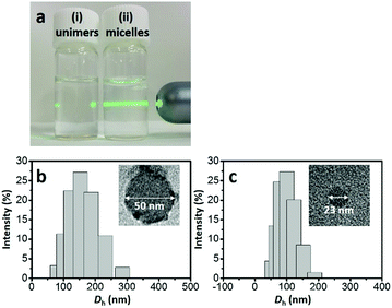
In the synthetic procedure, the asymmetric triblock copolymer (PS-b-P2VP-b-PEO) was completely dissolved as unimers in THF (Fig. 1a(i)). An optimal amount of 35% HCl solution was used to stimulate the micellization (Fig. 1a(ii)), forming the core–shell–corona type micelles, because the hydrophobic PS unit prefers to self-assemble as a PS core in order to reduce the interfacial energy between the PS units and water. Low-molecular-weight phenolic resol resin is a well-known carbon source, owing to several advantages including high thermal stability and easy conversion to carbon with high yield.25 Under acidic conditions, PEO, P2VP, and phenolic resol are protonated. Thus, the formation of the PS-b-P2VP-b-PEO/resol complex is essentially driven by counter anions (e.g., Cl−) through S+X−I+ type interaction, which is well known in the synthesis of mesoporous materials.26,27 Heating the sample to 130 °C under hydrothermal conditions promoted further cross-linking of the phenolic resol resin on the PS-b-P2VP-b-PEO micelles, resulting in brown-colored precipitates. Next, the resin-decorated PS-b-P2VP-b-PEO micelles were thermally decomposed to carbon in an inert atmosphere. Thermogravimetric analysis for pure PS-b-P2VP-b-PEO shows complete decomposition up to 400 °C under a N2 flow (Fig. S1, ESI†). Several types of HCNs were prepared by using different annealing temperatures: HCN-800, HCN-900, and HCN-1000. In our notation, the number (i.e., HCN-###) denotes the annealing temperature. The full experimental details are given in the ESI.†
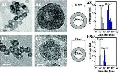
Transmission electron microscopy (TEM) was used to image the micelles. Phosphotungstic acid (0.1 wt%) highlights the PS core area of the micelles.28,29 The calculated diameter in the TEM images was ca. 50 nm (Fig. 1b). Dynamic light scattering (DLS) shows that the micelles are highly monodisperse with a hydrodynamic diameter (Dh) of ca. 150 nm. Since the Dh value includes the contributions from the extended P2VP and PEO units in the solution, the value is expected to be larger than the value measured by TEM. After carbonization, HCN-800 had an outer diameter of 63 nm while the diameter of the hollow core was 26 nm (Fig. 2a). The volume shrinkage was symmetrical during the carbonization process, so the particles maintained their spherical shape. SEM images of the samples before and after carbonization are shown in Fig. S2 (ESI†). It is clear that the average particle size of HCN-800 (annealed at 800 °C for 4 h) became smaller after annealing, although the spherical morphology was still well preserved and maintained the narrow particle size distribution.
One possible strategy to control the size of the hollow cores is to make PS-b-P2VP-b-PEO micelles with different PS lengths. But synthesizing multiple types of block copolymers is time consuming and expensive. Instead we used different solvent conditions to decrease the PS core size and the Dh value of the micelle. The micelle solution was transferred into a dialysis membrane tube and dialyzed several times to completely remove THF (see the detailed experimental conditions in the ESI†). DLS shows the Dh value decreased from ca. 150 nm to ca. 90 nm. In TEM a dense core with a diameter of ca. 23 nm was observed (Fig. 1c). After carbonization the sample had an outer diameter of 43 nm and a hollow core of 19 nm (Fig. 2b). Thus, we could shrink the size of the hollow core from 26 nm to 19 nm simply by changing the solvent composition. This sample is denoted as HCN-800-S. Dai et al. also found that different solvents influenced the particle size distribution, but the mechanism was unclear.30 Fortunately, an instructive mechanism is provided here. To the best of our knowledge, this size of the hollow core is one of the smallest values reported in the literatures (Table S1, ESI†).
Both HCN-900 and HCN-1000 samples were prepared via the same method but they were annealed at 900 °C and 1000 °C, respectively. Their spherical structure and the narrow distributions of the inner and outer diameters are shown in Fig. S3 (ESI†). N2 adsorption–desorption isotherms for the three types of HCNs are shown in Fig. S4 (ESI†). All the samples have the characteristic type IV isotherms, with similar hysteresis loops at the pressure range of 0.45–0.90. At pressures <0.1, the high N2 uptake indicates the presence of massive micropores. These results indicate that higher annealing temperatures burn away more polymeric precursors and generate micropores. Therefore, HCN-1000 demonstrates the highest N2 uptake at relatively low pressure and possesses the largest surface area of 1475.5 m2 g−1, compared to 906.3 m2 g−1 for HCN-900 and 835.2 m2 g−1 for HCN-800. The percentages of micropore volumes are 6.9% (HCN-800), 15.7% (HCN-900), and 20.9% (HCN-1000), respectively (Table S2, ESI†). High annealing temperatures enable the formation of a larger amount of micropores, thus increasing the surface area.
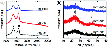
Raman spectroscopy is a useful tool to identify carbon phases. All the HCNs exhibit D-band (∼1340 cm−1) and G-band (∼1590 cm−1) scattering (Fig. 3a).31,32 The D-band corresponds to a disordered sp3 carbon or a defective graphitic structure, while the G-band is a graphitic sp2 carbon. The peak ratios of IG/ID reflect the degree of graphitization of the carbon. HCN-900 had the highest IG/ID value of 1.09, compared to 0.99 for HCN-800 and 0.97 for HCN-1000. Interestingly, HCN-900 had the highest degree of graphitization. From wide-angle powder XRD patterns, the (002) peak indicative of graphitization for HCN-900 is the strongest, in agreement with Raman data (Fig. 3b). It is known that the applied carbonization temperature is critical to achieve a high level of graphitization. In general, increasing the applied temperature can induce graphitization of amorphous carbon on metals (e.g., cobalt and iron). In the absence of metal catalysts, high-applied temperatures can cause rapid thermal cracking. This results in decomposition of the carbon source and growth of amorphous carbon. Previous reports have also demonstrated that disordered carbon materials are obtained at elevated temperatures.33,34
 | ||
| Fig. 3 (a) Raman spectroscopy and (b) wide-angle XRD profiles of HCN-800 (black), HCN-900 (red), and HCN-1000 (blue), respectively. | ||
Supercapacitors are ideal devices for rapid charge and discharge cycles owing to their high-power density, long lifetime, and wide operation temperatures. Recently, work on supercapacitors has been focused on making carbon materials with higher surface areas and optimized porous structures.35,36 Based on our structural and morphological analyses, we expect that these well-developed HCNs can be a promising material for use in EDLC applications because they possess good graphitization and hierarchical pore architectures that enable faster diffusion rates for the ions.
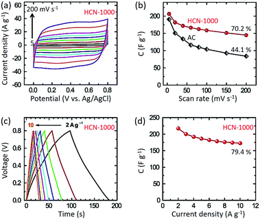
Standard three-electrode cyclic voltammetry (CV) studies were carried out for all the samples in 1 M H2SO4 electrolyte. HCN-1000 (206.4 F g−1) shows the highest specific capacitance compared to HCN-800 (162.3 F g−1) and HCN-900 (177.0 F g−1) at 5 mV s−1 (Fig. S5, ESI†). Thus, for our further studies we selected HCN-1000 as the best sample. As shown in Fig. 4a, the CV studies were carried out at various sweep rates from 5 to 200 mV s−1. The capacitance value at a sweep rate of 5 mV s−1 is 206.4 F g−1, which decreased to 144.0 F g−1 at a scan rate of 200 mV s−1 (70% retention) (Fig. 4b). Though some of previously reported materials have shown a high capacitance performance (Table S3, ESI†), their capacitance retention was poor compared to our studies.37,38 This is likely the advantage of the smaller diameter of our carbon sample by enabling easier intercalation and de-intercalation of ions at high scan rates.
Interestingly, the capacitance performance of HCN-1000 is better than commercially available activated carbon (AC) at the low scan rate of 5 mV s−1 (190 F g−1). At higher scan rates, the AC shows poor capacitance retention (only 44%) (Fig. 4b). The AC sample possesses mostly micropores, whereas our sample possesses hierarchical pores with mesopores and micropores (Table S2, ESI†).39 With increasing scan rates, the micropores make it difficult to (de)-intercalate ions, diminishing performance.40 However, the presence of hollow cores in our sample assists in the (de)-intercalation of ions to preserve the original CV shape at high scan rates without much distortion (Fig. S6, ESI†).
Galvanostatic charge–discharge studies show typical triangular profiles at various current densities from 2 to 10 A g−1. From Fig. 4c, it is clear that the discharge profiles are quite linear without any IR drop. The highest capacitance value of 217 F g−1 was obtained at a current density of 2 A g−1, which is in good agreement with the CV studies (Fig. 4b). At the higher current density of 10 A g−1, the capacitance value was still 172 F g−1, maintaining 79% of the value at 2 A g−1 (Fig. 4d). In the light of these results, we believe that these hollow carbon materials are a promising candidate for supercapacitor applications.
In summary, we have demonstrated a new method using triblock copolymer PS-b-P2VP-b-PEO micelles to synthesize small, spherical HCNs. DLS and TEM results clearly show an obvious change of PS core sizes before and after the THF removal. Our HCNs with an outer diameter of 43 nm and a hollow core of 19 nm are some of the smallest particles reported presently. Furthermore, we demonstrated how our HCN materials can be used as high-performance materials for EDLCs, because they largely retain the characteristic rectangular shape of their CV curves and high retention ratios even at high sweep rates. In the future, we hope to expand this method to create various types of heteroatom doped HCN materials.
This research was partially supported by a Postdoctoral Fellowship of Japan Society for the Promotion of Science (JSPS).
Notes and references
- S. J. Yang, T. Kim, J. H. Im, Y. S. Kim, K. Lee, H. Jung and C. R. Park, Chem. Mater., 2012, 24, 464 CrossRef CAS.
- J. Tang, N. L. Torad, R. R. Salunkhe, J.-H. Yoon, M. S. A. Hossain, S. X. Dou, J. H. Kim, T. Kimura and Y. Yamauchi, Chem. – Asian J., 2014, 9, 3238 CrossRef CAS PubMed.
- B. Liu, H. Yao, W. Song, L. Jin, I. M. Mosa, J. F. Rusling, S. L. Suib and J. He, J. Am. Chem. Soc., 2016, 138, 4718 CrossRef CAS PubMed.
- S. Liu, N. Tian, A.-Y. Xie, J.-H. Du, J. Xiao, L. Liu, H.-Y. Sun, Z.-Y. Cheng, Z.-Y. Zhou and S.-G. Sun, J. Am. Chem. Soc., 2016, 138, 5753 CrossRef CAS PubMed.
- F. Zheng, Y. Yang and Q. Chen, Nat. Commun., 2014, 5, 5261 CrossRef CAS PubMed.
- J. Xie, X. Yao, Q. Cheng, I. P. Madden, P. Dornth, C.-C. Chang, W. Fan and D. Wang, Angew. Chem., Int. Ed., 2015, 54, 4299 CrossRef CAS PubMed.
- T. Lin, I-W. Chen, F. Liu, C. Yang, H. Bi, F. Xu and F. Huang, Science, 2015, 350, 1508 CrossRef CAS PubMed.
- J. Tang, R. R. Salunkhe, J. Liu, N. L. Torad, M. Imura, S. Furukawa and Y. Yamauchi, J. Am. Chem. Soc., 2015, 137, 1572 CrossRef CAS PubMed.
- Z. Fan, J. Yan, L. Zhi, Q. Zhang, T. Wei, J. Feng, M. Zhang, W. Qian and F. Wei, Adv. Mater., 2010, 22, 3723 CrossRef CAS PubMed.
- H. Tian, Z. Lin, F. Xu, J. Zheng, X. Zhuang, Y. Mai and X. Feng, Small, 2016, 23, 3155 CrossRef PubMed.
- C.-T. Hsieh, S.-M. Hsu, J.-Y. Lin and H. Teng, J. Phys. Chem. C, 2011, 115, 12367 CAS.
- F. Xu, Z. Tang, S. Huang, L. Chen, Y. Liang, W. Mai, H. Zhong, R. Fu and D. Wu, Nat. Commun., 2015, 6, 7221 CrossRef PubMed.
- D. Lozano-Castelló, M. A. Lillo-Ródenas, D. Cazorla-Amorós and A. Linares-Solano, Carbon, 2001, 39, 741 CrossRef.
- K. Kierzek, E. Frackowiak, G. Lota, G. Gryglewicz and J. Machnikowski, Electrochim. Acta, 2004, 49, 515 CrossRef CAS.
- G. Zheng, S. W. Lee, Z. Liang, H.-W. Lee, K. Yan, H. Yao, H. Wang, W. Li, S. Chu and Y. Cui, Nat. Nanotechnol., 2014, 9, 618 CrossRef CAS PubMed.
- F. Böttger-Hiller, P. Kempe, G. Cox, A. Panchenko, N. Janssen, A. Petzold, T. Thurn-Albrecht, L. Borchardt, M. Rose, S. Kaskel, C. Georgi, H. Lang and S. Spange, Angew. Chem., Int. Ed., 2013, 52, 6088 CrossRef PubMed.
- J. Tang, J. Liu, R. R. Salunkhe, T. Wang and Y. Yamauchi, Chem. Commun., 2016, 52, 505 RSC.
- C. Zhang, H. B. Wu, C. Yuan, Z. Guo and X. W. Lou, Angew. Chem., Int. Ed., 2012, 51, 9592 CrossRef CAS PubMed.
- Z. Wang, S. Zhang, L. Zhang, R. Lin, X. Wu, H. Fang and Y. Ren, J. Power Sources, 2014, 248, 337 CrossRef CAS.
- A. Khanal, Y. Inoue, M. Yada and K. Nakashima, J. Am. Chem. Soc., 2007, 129, 1534 CrossRef CAS PubMed.
- D. Liu and K. Nakashima, Inorg. Chem., 2009, 48, 3898 CrossRef CAS PubMed.
- B. P. Bastakoti, S. Ishihara, S.-Y. Leo, K. Ariga, K. C.-W. Wu and Y. Yamauchi, Langmuir, 2014, 30, 651 CrossRef CAS PubMed.
- Y. Li, B. P. Bastakoti, M. Imura, S. M. Hwang, Z. Sun, J. H. Kim, S. X. Dou and Y. Yamauchi, Chem. – Eur. J., 2014, 20, 6027 CrossRef CAS PubMed.
- Y. Li, B. P. Bastakoti, V. Malgras, C. Li, J. Tang, J. H. Kim and Y. Yamauchi, Angew. Chem., Int. Ed., 2015, 54, 11073 CrossRef CAS PubMed.
- J. Liu, N. P. Wickramaratne, S. Z. Qiao and M. Jaroniec, Nat. Mater., 2015, 14, 763 CrossRef CAS PubMed.
- J. Wei, Y. Liang, X. Zhang, G. P. Simon, D. Zhao, J. Zhang, S. Jiang and H. Wang, Nanoscale, 2015, 7, 6247 RSC.
- G. J. de A. A. Soler-Illia, C. Sanchez, B. Lebeau and J. Patarin, Chem. Rev., 2002, 102, 4093 CrossRef PubMed.
- V. H. Pérez-Luna, J. E. Puig, V. M. Castaño, B. E. Rodriguez, A. K. Murthy and E. W. Kaler, Langmuir, 1990, 6, 1040 CrossRef.
- M. Sasidharan, D. Liu, N. Gunawardhana, M. Yoshio and K. Nikashima, J. Mater. Chem., 2011, 21, 13881 RSC.
- Z.-A. Qiao, B. Guo, A. J. Binder, J. Chen, G. M. Veith and S. Dai, Nano Lett., 2013, 13, 207 CrossRef CAS PubMed.
- Y. K. Kim, S. Cha, S. H. Hong and Y. J. Jeong, J. Mater. Chem., 2012, 22, 20554 RSC.
- N. Brun, S. R. S. Prabaharan, C. Surcin, M. Morcrette, H. Deleuze, M. Birot, O. Babot, M.-F. Achard and R. Backov, J. Phys. Chem. C, 2012, 116, 1408 CAS.
- R. Zhang, Y. Zhang, Q. Zhang, H. Xie, W. Qian and F. Wei, ACS Nano, 2013, 7, 6156 CrossRef CAS PubMed.
- O. Yu, D. Li, W. Cao, S. Shi and L. Chen, Nanoscale Res. Lett., 2009, 4, 574 CrossRef CAS PubMed.
- J. Huang, B. G. Sumpter and V. Meunier, Chem. – Eur. J., 2008, 14, 6614 CrossRef CAS PubMed.
- E. Frackowiak, Phys. Chem. Chem. Phys., 2007, 9, 1774 RSC.
- X. Fang, J. Zang, X. Wang, M.-S. Zheng and N. Zheng, J. Mater. Chem. A, 2014, 2, 6191 CAS.
- K. Xie, X. Qin, X. Wang, Y. Wang, H. Tao, Q. Wu, L. Yang and Z. Hu, Adv. Mater., 2012, 24, 347 CrossRef CAS PubMed.
- L.-F. Chen, X.-D. Zhang, H.-W. Liang, M. Kong. Q.-F. Guan, P. Chen, Z.-Y. Wu and S.-H. Yu, ACS Nano, 2012, 6, 7092 CrossRef CAS PubMed.
- F. Xu, R. Cai, Q. Zeng, C. Zou, D. Wu, F. Li, X. Lu, Y. Liang and R. Fu, J. Mater. Chem., 2011, 21, 1970 RSC.
Footnote |
| † Electronic supplementary information (ESI) available: Synthesis and characterization data of HCNs. See DOI: 10.1039/c6cc07360c |
| This journal is © The Royal Society of Chemistry 2017 |


