
Recent developments in 3D printable composite materials
Umme Kalsooma,
Pavel N. Nesterenkoab and
Brett Paull*ab
aAustralian Centre for Research on Separation Science (ACROSS), School of Physical Sciences, University of Tasmania, Private Bag 75, Hobart, Tasmania 7001, Australia
bARC Centre of Excellence for Electromaterials Science (ACES), School of Physical Sciences, University of Tasmania, Private Bag 75, Hobart, Tasmania 7001, Australia. E-mail: brett.paull@utas.edu.au
First published on 15th June 2016
Abstract
3D printing technology is now frequently employed in many areas of research and development. However, a relatively narrow range of 3D printable materials with a limited spectrum of physico-chemical properties still restricts the true potential of this potentially disruptive technology. There is rapidly increasing interest in the improvement and diversification of properties of generic printing materials via the introduction of fillers with unique properties, and/or by blending materials exhibiting different properties to generate high performance composites. 3D printed composites have already been utilised in a wide range of applications, including biomedical, mechanical, electrical, thermal and optically enhanced products. The increasing popularity of 3D printed composites can be attributed to the ability to fabricate complex geometries, low cost production, and other advantages associated with rapid prototyping. This review covers all the recent reports in which the properties of generic 3D printable materials have been modified either by adding nanoparticles, fibers, other polymers, or by a chemical reaction for fabrication of composites with enhanced biomaterial, mechanical, electrical, thermal, optical and other properties.
Introduction
Additive fabrication technologies, commonly referred to as 3D printers, have seen an exponential increase in use in recent years, as a versatile and low cost technology for rapid casting/prototyping.1 Applications of this technology within a diverse range of industries continue to grow, exploiting the expanding capabilities of advanced 3D printers to produce a range of materials, together with complex monolithic structures and geometries, with micrometre resolution for some applications.2–4 In comparison to traditional fabrication approaches, in which a complex structure is manufactured via assembly of individual parts, 3D printing allows layer by layer (bottom to top) printing of predefined slices of the designed and desired object,5 resulting in rapid manufacturing of complex objects, practically unhindered by design complexity, thus providing substantial liberty in new and untested geometric designs.However, current manufacturing using 3D printing is overwhelmingly based upon single material printing, typically with a limited range of commercial and often proprietary resins. The obvious issue here is this relatively limited range of materials compatible with printer technologies (and commercial printers) and hence, limited variation in the physical and chemical properties of printed objects.6 This issue is being addressed somewhat with modern multi-material 3D printers, which provide for some control of material composition and properties, and which can provide for composite printing through multiple printer heads, providing the capability to print blended and/or layered composite materials, and from which objects with features of variable and gradient functionality can be produced.7
Running parallel to these technological developments, there has also been rapidly growing interest in the pre-blending of materials and/or the inclusion of ‘fillers’ into printable resins, which deliver distinct physicochemical properties into the resultant materials, thus producing 3D printed composites which exhibit unique characteristics and capabilities.8–15 Indeed, in the area of composite design and production, 3D printing represents a technology with immense potential, again providing low cost, simple and rapid prototyping advantages over traditional methods for fabrication of composite materials and objects.16
In the wider fields of material and chemical sciences, the impact of 3D printing, as witnessed by the proliferation of review articles on the subject, is very obvious. In the area of 3D printed composite materials this is not yet the case. In 2010 Kumar and Kruth published their review on the variety of 3D printed composites for biomedical, mechanical, electrical, thermal, magnetic and optical applications.14 However, over the subsequent 6 years there has been considerable developments and achievements in this fast growing area, and hence the focus of this current review is to summarise and critique these recent advances. Herein, we present and discuss the latest progress in the development of 3D printable composite materials, their fab-rication methods, applications, advantages and limitations. A detailed overview of printers, matrices and additives used for the development of 3D printable composite materials provided in Tables 1, and 2 describes properties and applications of the resultant 3D printed composites.
| Printer/printing type | Matrix | Additives/fillers | Ref. |
|---|---|---|---|
| Inkjet | Bioactive glass | HA (40 wt%) | 10 |
| Inkjet | Calcium phosphate | Calcium sulphate | 38 |
| Inkjet | HA (60 wt%) | TCP (40 wt%) | 17 |
| Inkjet | TCP | SiO2 (0.5 wt%) and ZnO (0.25 wt%) | 19 |
| Calcium silicate | Ce | 107 | |
| 4th 3D Bioplotter™ | PCL (38.5 wt%) and bioactive glass (52.3–61.5 wt%) | Fe3O4 (0–9.3 wt%) | 12 |
| FDM | PLA | TCP | 46 |
| FDM | Polyamide | HA (5 wt%) and zirconium oxide (15 wt%) | 47 |
| Inkjet | β-TCP | Mg (∼2.12 wt%) | 41 |
| Inkjet | Bioactive glass (60 wt%) | TCP (40 wt%) | 37 |
| FDM (mini extrusion) | PCL | TCP (10–30 wt%) | 40 |
| Inkjet | Calcium phosphate | Collagen (1.5 wt%) | 33 |
| SLS | Calcium phosphate (0–100 wt%) | HA (100–0 wt%) | 39 |
| FDM | PCL | Graphene | 50 |
| Inkjet | Apatite–wollastonite glass ceramic | HA | 108 |
| Inkjet | HA (50–60 wt%) | PVOH (40–50%) | 42 |
| FDM | Thermoplastic polymer | Natural fibre | 23 |
| Direct print tool | Poly lactic acid | Bioactive glass (50 wt%) | 18 |
| Melt electrospinning writing | Hydrogel | PCL microfibers (12% to 28%) | 49 |
| SLS | Forsterite (Mg2SiO4) 95, 90, 80, 70, 60 wt% | Nano-58S bioactive glass 5, 10, 20, 30, 40 wt% | 22 |
| Inkjet | Epoxy resin | SiC & carbon fibres (31 vol%) | 53 |
| — | PCL | Alginate (4 wt%), and phenamil methanesulfonate | 109 |
| FDM | ABS | Hydrous magnesium silicate | 64 |
| FDM and robocasting | Thermoplastic polymer | Steel (47 vol%) and zirconia (45 vol%) | 58 |
| SLA | Photopolymer | Graphene oxide (0.2 wt%) | 59 |
| SLA | UV sensitive resin | Magnetised Al2O3 particles | 62 |
| SLA | Hard photopolymer (proprietary acrylic-based photopolymer resins) | Soft photopolymer (20% v/v) | 2 |
| Tetracalcium phosphate | β-Tricalcium phosphate or calcium sulphate | 35 | |
| Inkjet | TCP | SrO (1 wt%) and MgO (1 wt%) | 20 |
| SLS | Calcium phosphate | Poly(hydroxybutyrate-co-hydroxyvalerate) | 21 |
| SLS | Carbonated HA | Poly(L-lactic acid) | 21 |
| Indirect 3D printing | Glass | β-Spodumene, lithium disilicate | 43 |
| PCL | Hydroxyapatite (25 wt%) | 45 | |
| Inkjet | Vaseline | TiO2 (2.5–10 wt%) | 65 |
| FDM | PDMS | ABS (anisotropic material) | 68 |
| Laser sintering | Polyamide | Carbon nanofiber (3 wt%) | 55 |
| FDM | ABS | CNTs (3 wt%) | 13 |
| Inkjet | WC (34 wt%) | ZrC (55 wt%) | 60 |
| TiC | Al–Si alloy | 61 | |
| Aerosol 3D printing | Poly-lactide-co-glycolide | Nano titania (30 wt%) | 34 |
| FDM | ABS | CNTs (3 wt%) | 110 |
| SLS | Zirconia (41.5 wt% and 80 wt%) | Alumina | 63 |
| Nozzle printing and inkjet printing | Elastomeric fibre | AgNP | 66 |
| SLA | 3D printable oil-in-water emulsion | AgNP | 90 |
| Paper based substrate | Graphene oxide, graphene hydrogel–polyaniline coating on the substrate | 89 | |
| Inkjet | CNTs | Gellan & xanthan (0.10 w/v%) | 80 |
| Inkjet | Poly(ethylene terephthalate) | PdCu, AgCu | 88 |
| Inkjet | Styrene-block-butadiene-block-styrene rubber fibres | Ag nanoparticles | 86 |
| Electrospray deposition | Polyvinylidene fluoride | Aluminum nanopowders (50 wt%) | 66 |
| Inkjet | Poly(2-methoxyaniline-5-sulfonic acid) | CNTs | 78 |
| FDM | PLA | CNTs | 82 |
| Robocasting | SiC | Graphene nanoplatelets (20 vol%) | 71 |
| FDM | Polycarbonate polymer | W | 74 |
| FDM | ABS | Copper and iron (10–50 wt%) | 100 |
| Polylactide | CNTs (5 wt%) | 73 | |
| Inkjet | Polylactide-co-glycolide | Graphene (60 vol%) | 76 |
| SLA | Photo resin | Al2O3 | 94 |
| SLS | Nylon-12 | Carbon black (4 wt%) | 85 |
| FDM | ABS | Twisted jute natural plant fibres and carbon fibres | 56 |
| SLA | Polyethylene glycol di-acrylate matrix | Barium titanate nanoparticles (10 mass%) | 87 |
| FDM | Polymorph thermoplastic | Carbon black (15 wt%) | 79 |
| FDM | ABS | Graphene flakes (5.6 wt%) | 97 |
| SLA | Photo resin | BST (50–60 wt%) | 101 |
| SLA | Epoxy resin | Diamond microparticles (30 w/v%) | 99 |
| FDM | PDMS | ABS, glass fibre reinforced polymer | 111 |
| FDM | ABS thermoplastic pellets | Carbon fibre powder (5 wt%) | 52 |
| Inkjet | Polymer | Quantum dots | 106 |
| Inkjet | Polymer | CdSe/ZnS quantum dot | 105 |
| Inkjet | Polyaniline, poly(3,4-ethylenedioxythiophene) | Silica | 102 |
| FDM | ABS or polypropylene | BaTiO3/Ba0.64Sr0.36TiO3/CaTiO3 | 93 |
| FDM | ABS | BaTiO3 (70 wt%) | 95 |
| Composite | Composite properties | Application | Ref. |
|---|---|---|---|
| 3D printed composites for biomedical applications | Bending strength 80 MPa, Young's modulus 80 GPa, reduced and isotropic shrinkage in the composite | Bone and tissue replacement | 10 |
| Enhanced compressive strength | Tissue engineered bone scaffolds | 38 | |
| Porosity 53.1%, bulk density 93.9 g cm−3, enhanced biocompatibility | Bone substitutes | 17 | |
| Enhanced mechanical and biological properties | Scaffolds | 19 | |
| Porosity (60%), enhanced compressive strength (13–16 MPa), magnetic heating, bioactivity, and osteogenic ability | Drug delivery and hyperthermia | 12 | |
| Enhanced mechanical strength and bone regeneration properties | Bone implants and scaffolds | 46 | |
| Tensile strength 22.78 MPa 761, tensile modulus 93 MPa, enhanced thermal stability increased viscosity and rate of crystallisation | Biomedical applications | 47 | |
| High bending strength (19.9 MPa), biocompatible, biodegradable | Bone implants | 16 and 37 | |
| Biocompatible, high mechanical strength, degradable | Bone implants | 33 | |
| Fracture toughness (1.33 MPa m1/2), compressive strength (18.35 MPa) | Bone scaffolds | 39 | |
| Compressive strength: 43.91 MPa, enhanced cell attachment and proliferation | Scaffolds | 22 | |
| Strength 120–140 MPa, compression 100 MPa, porosity ∼ 52% | Scaffolds | 41 | |
| Fracture strength = 21.01 MPa (sintering 1200 °C, 3 h, porosity = 51.49%) and 76.82 MPa (sintering 1300 °C, 3 h, porosity = 51.49%) and biological properties | 3D printed synthetic bone implants | 108 | |
| Porosity = 55%, compressive strength = 0.12–0.88 MPa, improved biological properties such as osteoconduction and osteointegration | Bone tissue engineering | 42 | |
| Biocompatible scaffolds, compressive modulus = 44.19–99.81 MPa | Bone tissue engineering | 18 | |
| Bending strength = 70 MPa, Young's modulus = 80 GPa, reduced and isotropic shrinkage from the sintering process | Bone and tissue replacement | 10. | |
| Ink viscosity = viscosity is ∼200 Pa s, Young's modulus = 8.06–24.54 GPa, strength = 43.9–66.2 MPa, light weight, exceptional mechanical properties | Bio inspired composite structures | 53 | |
| Porosity 38%, compression strength = 0.59–0.70 MPa, improved biocompatibility | Patient specific bone implants | 35 | |
| Mechanical strength 12.01 MPa, enhanced osteoid like new bone formation, and mineralization | Bone tissue engineering | 20 | |
| Compressive strength: calcium phosphate/poly(hydroxybutyrate-co-hydroxyvalerate) = 0.55 MPa, carbonated hydroxyapatite/poly(L-lactic acid) = 0.64 MPa, compressive Young's: calcium phosphate/poly(hydroxybutyrate-co-hydroxyvalerate) = 6.6 MPa carbonated hydroxyapatite/poly(lactic acid) = 6.2 MPa, enhanced cell proliferation | Bone scaffolds | 21 | |
| Compression strength of ∼15 MPa | Bone scaffold fabrication | 43 | |
| Compressive strength 0.26–0.47 MPa, enhanced proliferation | Bone tissue engineering | 45 | |
| Porosity = 55–57%, improved hydrophilicity, improved mechanical properties | Tissue engineering | 40 | |
| Improved bone tissue growth, Young's modulus 3.42 MPa, max. tensile strength 0.11 MPa | Tissue engineering | 109 | |
| Target drug delivery, improved mechanical and biological properties | Cell scaffolds | 50 | |
| Porosity 72–88%, equilibrium modulus 130 kPa, stiffness 214 kPa | Scaffolds | 49 | |
| 3D printed composites with enhanced mechanical properties | Strength = 43.9–66.2 MPa, Young's modulus = 8.06–24.54 GPa | Highly stiffed sandwich panels, energy absorbers, catalyst supports, and insulation | 53 |
| Stress 15 MPa, fracture resistant composites electrical conductivity increased from 10−12 to 10−5 S cm−1 | Bone implants | 2 | |
| Enhanced mechanical properties | Fully functioning end use parts | 55 | |
| Porosity 57.9%, ultra-high melting metal composites (>2500 °C), rapidly prototyping of near net shapes and dimensions | Aerospace vehicle, refractory rocket nozzle | 60 | |
| Tensile stress 24 MPa, strain ∼ 2% | High mechanical materials and components | 64 | |
| Porosity 32%, increased osteoblast growth, improved tensile modulus (1–2 MPa) and stress (0.1–0.25) | Bone tissue regeneration and drug delivery | 34 | |
| 10% increment in Young's modulus, improved mechanical strength | Engineering and technology education | 110 | |
| Flexural strength > 500 MPa | Frameworks for all-ceramic dental restorations, complex structures | 63 | |
| Flexural stress ∼ 60 MPa, flexural modulus ∼ 50 GPa | Aerospace, automotive, and medical | 52 | |
| For carbon–ABS composites = tensile modulus 19.5 MPa, strength 185.2 | Load-bearing components | 56 | |
| For plant fibre–ABS composites tensile modulus 5.11 MPa, strength 57.1 MPa | Load-bearing components | 56 | |
| Improved stiffness, strength and hardness | Applications in engineering disciplines | 62 | |
| Enhanced mechanical strength, multifunctional material | Fabrication of multifunctional materials | 58 | |
| Bending strength ∼ 233 MPa, fracture toughness 4.56 MPa m1/2 | Near net shape composites | 61 | |
| 3D printable composite materials with enhanced bending/twisting strength | Large deformations, coupling of in-plane/bending/twisting deformations | Mobile phone, robotics | 68 |
| Lower deformation tendency, improved elastic properties and enhanced shape preserving | Flexible electronics, memristor etc. | 65 | |
| Lower Young's modulus than in the compressed samples, porosity (around 20%) | Bio composites | 23 | |
| Large deformations, complex morphed shapes | Morphing for overcoming the geometric constraints of structures or actuators | 111 | |
| 3D printed electrically active composite materials | Sheet resistance 8.1 and 4.9 Ω sq−1, optical transmittance of 79% and 65% at 500 nm for PdCu and AgCu respectively, electrically conducting | Smart phones, touch screens, light-emitting diodes and thin-film solar cells | 88 |
| High bulk conductivity, preserved at large deformations (σ ≈ 2200 S cm−1 at 100% strain for a 150 μm-thick mat), stretchable & electrically conducing | Stretchable antenna, sensor and light emitting diodes | 86 | |
| Optical transparency 85%, sheet resistance of 100 kΩ−1 electrically conducting | Electronics | 78 | |
| Tensile strength 69.4 MPa, electrically conducting | Electrical and mechanical | 13 | |
| Resistivity in-plane with the layers = 0.0960.01 ohm m−1 and perpendicular to the layers = 0.1260.01 ohm m−1 | Electronic sensors, capacitive buttons | 79 | |
| Transmittance 99%, resistance of composites (Ramb > 12 MV) lower compared to the resistance of gellan (Ramb > 350 MV), electrically conducting | Actuators and sensors | 80 | |
| Electrical conductivity 1 × 10⁻⁴ S cm−1, flexural modulus 1450 MPa | Electrically conducting material | 85 | |
| Electrical conductivity 611 S m−1, strength 10–50 MPa | Scaffolds | 71 | |
| Electrical conductivity was about 23 S m−1 | Helical sensors | 73 | |
| Electrical conductivity = 10–100 S m−1 | Conductive micro structures | 82 | |
| Resistance 1 ± 0.2 Ω | 3D connector of an electrical circuit | 90 | |
| Dielectric material | Electrical conductivity 18 Ω sq−1 | Flexible and lightweight paper electrode | 89 |
| Piezoelectric coefficients (d33) of ∼40 pC N−1 | Fabrication of bio diagnostics, nano and microelectromechanical systems, imaging, sensors, and electronics | 87 | |
| Improved electromagnetic properties, X-ray radiation shielding | Space-based applications | 74 | |
| Electrical conductivities greater than 800 S m−1, enhanced cell adhesion, viability, and proliferation | Electronics and scaffolds | 76 | |
| Permittivity 2.6–8.7, loss tangents 0.005–0.027, dielectric material | Photonic crystals, electronics, communications | 95 | |
| Improved permittivity, low dielectric loss tangent value | Insulating spacers/components | 94 | |
| Dielectric permittivity = 5–7, dielectric loss tangent = 3 × 10⁻² to 5 × 10⁻³ | Artificial insulating material | 93 | |
| 3D printed composite materials with controlled thermal properties | Linear thermal coefficient > 75 ppm °C−1, electrical conductivity = 1.05 × 10⁻³ S m−1. Thermally conducting | Thermally conducting materials | 97 |
| Tensile strength 47.82 MPa, tensile modulus 2362 MPa, the flexural strength 73.12 MPa | Thermally conducting materials | 98 | |
| Improved heat transfer ability, co-efficient of linear thermal expansion 48 × 10−6 ± 3.6 × 10⁻⁶ K−1, increase in contact angle 98.7 θ | Heat sink and cooling system | 99 | |
| Thermal conductivity of 0.2 W m−1 K−1 | Thermoelectric material | 101 | |
| Porosity 27.4%, improved thermal stability | Rocket motors | 66 | |
| Coefficient of thermal expansion = 50 ppm °C−1, tensile stress 26–45 MPa, tensile modulus 906–978 MPa | Thermo-mechanical materials | 100 | |
| 3D printed composites with enhanced optical properties | Luminous efficiency 0.1 lm W−1 for the blue phosphor driven with 420 V at 31 kHz, enhanced optical properties | Luminescent light-converting thin films for AC electroluminescent displays | 106 |
| Optically active | Full colour AC-driven displays | 105 | |
| Optically active | Electrochromic devices |
3D printable composite materials for biomedical applications
The key issues for consideration in the 3D printing of composite objects for biomedical applications include biocompatibility,18–23 mechanical strength,24,25 and improved biomimicking of tissues structures.26 Bone scaffolds, porous structures with highly interconnected networks of channels, are used for bone tissue engineering and to provide a template for initial attachment of patient-derived cells, to facilitate subsequent formation of tissues.27 The precise control of a scaffold's pore size, shape, interconnections and other architectural parameters is essential to ensure efficient nutrient diffusion, blood flow, manipulation of tissue differentiation, to achieve optimal mechanical strength,24,25 and where necessary biodegradability. The ability of 3D printing technology to fabricate such features both internally and externally upon a structure, more or less independently of shape and design28 makes this technique highly suitable for the fabrication of complex-shaped porous ceramic scaffolds, with such well-defined internal 3D architecture and pores structures. Thus 3D printing has recently been applied to the generation of highly specific bone implants,12,17–19,25,27,29–34 with size and shape precisely matching the bone defects in patients, often utilising the patients' scanned anatomical information to optimise and produce a custom-made implant.30 Fig. 1 shows one such example of a custom made 3D printed implant for oral and maxillofacial surgery.17 | ||
| Fig. 1 An example of 3D printed implant fabricated for oral and maxillofacial surgery. Reproduced with permission.17 | ||
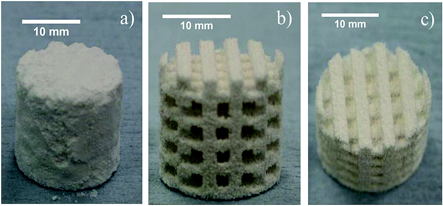
Inkjet-based 3D printing has been frequently employed to fabricate calcium phosphate scaffolds (CPS).19,33,35–38 In inkjet printing, the calcium phosphate powder is temporarily bound by an adhesive polymer, typically followed by sintering of the printed body at high temperature for permanent binding.27,29 Composite materials for scaffold fabrication by inkjet printing have been developed to create objects with varying geometric complexity. For example, Khalyfa et al. (2007) developed a 3D printable composite powder consisting of tetracalcium phosphate (Ca4(PO4)2O) as a reactive component, and β-tricalcium phosphate (β-TCP) or calcium sulfate as biodegradable fillers. An aqueous solution of citric was used as a binder. Using the developed powder–binder system, various light weight objects with complicated internal and external architecture and designs were fabricated (see Fig. 2(a)). Composite objects with complex geometries and channels with various diameter (1–2 mm) and inter-channel distances were fabricated to study the printing parameters, such as accuracy and feature resolution (see Fig. 2(b)). However, the authors reported the fabrication of channels smaller than 1 mm as ‘challenging’ due to difficulties in the removal of unbound materials from within the printed channels. The objects produced using the developed powder binding system also showed relatively low compression strengths due to the high microporosity of the material, and required a post-processing procedure to improve the mechanical strength.35
 | ||
| Fig. 2 (a) 3D printed cranial segment, (b) 3D printed cuboid object consisting of channels with various diameter and channel distance fabricated from composite powder binder mixture of tetra-calcium phosphate and β-TCP. Reproduced with permission.35 | ||
The issue of low compressive strength of ceramic scaffolds comprised of highly porous calcium phosphate31 has been addressed by blending TCP powder with hydroxyapatite (HA),39 calcium sulphate,38 and polycaprolactone (PCL)40 to develop composite materials exhibiting significantly enhanced mechanical properties. Following this approach, Shuai et al. (2013) prepared calcium phosphate scaffolds consisting of TCP/HA with composition ratios varying from (0/100, 10/90, 30/70, 50/50, 70/30 and 100/0) and observed an improvement in fracture toughness and compressive strength with increasing TCP from 0 to 30 wt%, and a decrease in mechanical strength above 30 wt%.39 Similarly, calcium phosphate powders were blended with the calcium sulfate (CaSO4)-based powder to develop composite materials. Using this printable material, highly resolved objects with improved compressive strength could be produced with inkjet printing.38
In addition to mechanical strength, biodegradability41 and controlled bioactivity are other important concerns when developing materials for the fabrication of scaffolds with potential to stimulate bone regeneration, cell proliferation or combat infection.18–22 Such biological properties of scaffolds can be enhanced by the addition of appropriate fillers into the matrix powder. For example, Fielding et al. (2012) incorporated ZnO and SiO2 into calcium phosphate powder for the development of composite material with enhanced mechanical and biological properties. Using these materials, various composites and pure tricalcium phosphate scaffolds were fabricated by inkjet printing, followed by sintering at high temperature (1250 °C)19 which is usually carried out to facilitate the permanent binding of the calcium phosphate powder.38 The scaffolds developed using the new composite materials showed up to 250% improvement in compressive strength and enhanced cellular attachment characteristics in comparison to pure TCP scaffolds. Similarly, the addition of SrO and MgO, and Ce to calcium phosphate powder have been investigated for the development of composite scaffolds with improved osteogenesis capability and compressive strength.20,107
The formation of glass/ceramic composites using both inkjet printing37 and indirect 3D printing43 and has been described for applications in bioresorbable, largescale bone implants. In indirect printing, a negative mould is constructed based on the scaffold design, which is later used for casting of the desired biomaterial and then removed to acquire the final scaffold.44 However, each of these printing methods require sintering at high temperature, which has been reported to cause shrinking of the final material and thus requires pre-calculations of dimensional changes to achieve perfect fit. This is particularly the case for glass materials, where the sintering process depends on viscous flow and is usually associated with greater anisotropic shrinkage. Large and complex structures may significantly deform because of a number of factors, such as gravity, intrinsic strain or temperature, surface tension and density gradients.10 Such effects seen during the sintering of glass materials can be minimised by reducing the glass fraction of the composite materials.
Winkel et al. (2012) developed bioactive glass composites with HA powder to fabricate 3D scaffolds. Glass ceramic scaffolds with 40% HA content were fabricated by inkjet printing. The incorporation of HA to the bioactive glass material provided effective stabilisation of complex 3D-printed structure and a significant reduction in shrinking was observed during viscous sintering.10 Fig. 3 shows changes in the dimensions of the 3D printed composite scaffold, following the sintering process. As can be seen, sintering caused relatively small overall axial shrinkage (20%) in the pore size of the object fabricated from this composite material (as compared to the non-composite material).10
 | ||
| Fig. 3 (a) Computer model, (b) a photograph of 3D-printed green body, (c) sintered glass/HA composite structure (after heating to 750 °C at 2 K min−1) for testing the viability of the 3D printing process and the sinter model for optimized HAp content. Reproduced with permission.10 | ||
In addition to shrinkage and deformation, sintering at high temperature also precludes the options for integration of bioactive molecules and drugs that are useful for bone regeneration or preventing infection.31 However, low temperature inkjet printing has been employed for incorporation of bioactive materials. For example, formation of calcium phosphate composites with collagen, a bioactive polymer, has been applied to produce scaffolds with improved mechanical strength, cellular compatibility and bone ation into a non-load bearing bone defect. Furthermore the regenerative properties. Incorporation of collagen in TCP produced sufficiently strong scaffolds for handling and implant-degradability and osteoconductive properties of collagen enabled the final replacement of these scaffolds with the newly formed bone.33 Additionally, HA and poly(vinyl)alcohol (PVOH) were mixed (ratio 50![[thin space (1/6-em)]](https://www.rsc.org/images/entities/char_2009.gif) :50) to produced porous scaffolds to facilitate osteoconduction and osteointegration. The excessive powder from the pores of the 3D printed scaffold was effectively removed with the help of compressed air through a syringe needle (see Fig. 4). The pore size, surface roughness and non-designed porosity within the scaffold were considered promising factors for the promotion of osteoconduction and osteointegration.42
:50) to produced porous scaffolds to facilitate osteoconduction and osteointegration. The excessive powder from the pores of the 3D printed scaffold was effectively removed with the help of compressed air through a syringe needle (see Fig. 4). The pore size, surface roughness and non-designed porosity within the scaffold were considered promising factors for the promotion of osteoconduction and osteointegration.42
 | ||
| Fig. 4 Efficiency of compressed air for powder removal from 50 wt% HA–PVOH composites. (a) Printed scaffold before powder removal, (b and c) scaffolds after powder removal. Reproduced with permission.42 | ||
Composite materials consisting of polymers and ceramics has also gained increased popularity for scaffold fabrication because of the synergistic advantages of the mixed materials, such as high strength via the ceramic phase and toughness and plasticity induced by the polymeric phase.25 Liu et al. (2011), developed polymer scaffolds consisting of well-dispersed nano-sized ceramics. This nano-ceramic dispersion in the polymer matrix provided enhanced mechanical and biological properties and a close resemblance to the natural bones. These scaffolds facilitated greater cell adhesion, synthesis of collagen and deposition of calcium containing minerals.34 Aerosol based 3D printing, in which a dense aerosol consisting of tiny droplets is sprayed layer by layer on the deposition platform, was employed to allow the fabrication of highly ordered bone like structures, while preserving the dispersion of the nanoparticles in the polymeric matrix.34
Fused deposition modelling (FDM) based printing methods, in which a material in molten form is extruded layer by layer on the printing bed, has also been applied for scaffold fabrication. 3D printed polymeric scaffolds consisting of HA,45 bioactive glass, magnetic particles incorporated into mesoporous bioactive glass materials,12 TCP,46 and zirconium oxide,47 have all been manufactured using FDM printing. The composite scaffolds produced present a number of promising platforms for bone regeneration, with enhanced properties reported, including superior bioactivity, osteogenic ability, and mineralization of human bone marrow-derived mesenchymal stem cells. Fig. 5 shows mineralization of human bone marrow-derived mesenchymal stem cells on one such composite scaffold. As it can be seen, a larger number of mineralized nodules were observed on the composite scaffolds consisting of 5, 10, 15 wt% of Fe3O4. These scaffolds have application in the reconstruction of bone defects generated by bone tumour resection or any other means.12 Polymeric composite material consisting of HA and bioactive glass support local angiogenesis and bone healing, and improve mechanical strength, cell adhesion and proliferation properties of the composite scaffolds.45,48
 | ||
| Fig. 5 Mineralisation of human bone marrow-derived mesenchymal stem cells on the bioactive glass/PCL, composite with Fe3O4 (a) 5% wt, (b) 10% wt, (c) 15% wt, (d) cultured scaffolds after 14 days. Reproduced with permission.12 | ||
A major limitation of melt extrusion based printing processes is that the production of smaller diameter filaments is challenging, as the minimum filament diameter is typically 50–100 μm. However, an alternative 3D printing technique, capable of printing well below the limits of traditional FDM technology is known as melt electrospinning writing, and has also been employed for development of composite polymer scaffolds. In this printing process, fibrous structures are produced from polymer melts with filament diameters as small as 5 μm. Using this technology composite scaffolds consisting of soft hydrogels reinforced with structured and highly porous micro-fibre networks have been manufactured. The stiffness and elasticity of these composites scaffolds is reported as being comparable to articular cartilage tissues.49
An exciting development in 3D printing is the capability to print biofunctional composite structural materials. The development of polymeric material blended with both drugs50 and antibiotics,51 have recently been reported. For example, the development of a 3D printable material loaded with antibiotics for application in treating chronic diseases was recently described by Shim et al. (2015). For preparation of this biofunctional composite material, PCL and poly(lactic-co-glycolic acid) (PLGA) pellets were melted at 110 °C in a glass dish (Fig. 6).
 | ||
| Fig. 6 Schematic illustration of preparation and printing of antibiotic loaded composite material. Reproduced with permission.51 | ||
To this molten polymeric mixture, tobramycin (antibiotic) powders were added and stirred to achieve homogeneous mixing of all components. The composite mixture was extruded from a 3D printer for the fabrication of scaffolds for chronic osteomyelitis treatment.51 A schematic of the material preparation and printing process is given in Fig. 6.
3D printed composites with enhanced structural and mechanical properties
3D printing materials with intrinsically limited mechanical strength and durability have been combined with fillers to develop composites with enhanced performance in these areas.52–59 Notably these enhanced materials have been developed for applications in aerospace, the automotive industry, wind energy and similarly high material performance demanding industries. A very recent and typical example is that reported by Ning et al. (2015), who added carbon fibres to a commercially thermoplastic resin matrix for FDM printing, to develop a new printable composite with enhanced mechanical properties.52 Using this technique, composite materials consisting of fibre content ranging from 3–15 wt% were developed and various mechanical properties, including flexural and tensile strength, were examined. Composite objects with 5 wt% carbon fibre (150 μm) content showed enhanced flexural stress, flexural modulus, and flexural toughness with an increase of 11.82%, 16.82%, and 21.86%, respectively, in comparison to the pure polymeric material. However, in this particular study the composites with 10 wt% carbon fibres actually showed worst tensile properties, due to the large porosity values in comparison to the other composites, as can be seen in SEM images of the fracture interface of the composites with various fibre contents, following tensile testing (see Fig. 7). | ||
| Fig. 7 SEM images of fracture interface of objects after tensile testing showing different porosity in different objects consisting of various carbon fibre content. Reproduced with permission.52 | ||
The organised alignment of micro-particulate and filimentaceous fillers within printed composites is also an advantage of 3D printing currently being explored. 3D printing potentially allows manipulation of the filler's alignment in the polymeric matrix during the printing process, in order to digitally integrate physical parameters such as composition, stiffness and toughness within the design components. For example, the 3D printing of cellular composites, consisting of a highly interconnected network of solid supports, has been enabled using composite material consisting of silicon carbide (SIC) whiskers and carbon fibres included within an epoxy resin. The alignment of fibres inside the composite matrix was controlled during printing, to manufacture hierarchical honeycomb structures with a close resemblance to natural balsa wood (see Fig. 8). This approach shows great potential for fabrication of a variety of bio-inspired composite objects with precise architecture and mechanical properties.53 Furthermore, reinforcement of 3D printable material with natural fibres has also been described, in one example for the fabrication of hygromorphic biocomposites that are capable of bending in response to a moisture gradient.23
 | ||
| Fig. 8 (a) 3D printing of the triangular honeycomb object fabricated from composite material, (b) schematic representation of the controlled alignment of fillers in the polymer matrix within the printer's nozzle during deposition of the composite ink on the printing bed. Reproduced with permission.53 | ||
In addition to introducing various fillers to the polymer matrix, the development of tough composites based upon two polymers of contrasting properties has also been described. For example, Dimas et al. (2013) fabricated tough biological composites with exceptional fracture resistance by integrating two acrylic photopolymers with significantly different mechanical properties. The resulting composite comprised of specific topological arrangements of soft and stiff phases. In comparison to traditional materials that are delicate and prone to catastrophic failure, these 3D printed synthetic composites exhibited superior mechanical strength with fracture and deformation mechanisms comparable to mineralised biological composites. Furthermore, in this instance 3D printing provided the added advantages of large scale, low cost fabrication of complex topologies, which could not be achieved using traditional fabrication methods.2
The use of mould free rapid 3D printing technology has also been described for fabrication of high strength,60,61 light weight,62 near net shape composites with complex geometries. ‘Near net shape’ is an industrial manufacturing term where the first fabrication of the object is very similar to the final (net) shape, preventing/minimising the requirement for surface finishing and therefore resulting in reduction of the production costs. These composites are traditionally prepared by hot pressing or cold pressing and are capable of only producing components with simple structures. However, using 3D printing complex structures with enhanced mechanical properties can be realised. 3D printing technology has been integrated with other manufacturing process to generate composites with extraordinary properties such as light weight, dense, and ultra-high melting capabilities.60 Metal printing techniques have also been used to enhance the mechanical properties of composite ceramics, such as the production of mixed zirconia–alumina based ceramics using selective laser melting (SLM) based printing. The printed crack free materials displayed a flexural strength of more than 500 MPa.63
Research have also been reported investigating the effect of fabrication parameters on the mechanical properties of such composite materials. For example, Christiyan et al. (2016) studied the influence of printing parameters, such as layer thickness and printing speed on the mechanical properties of an acrylonitrile-butadiene-styrene (ABS)–hydrous magnesium silicate composite. In this instance better results showing improved mechanical properties were obtained at a low printing speed and minimum layer thickness due to a better bonding between the layers.64
Nanoparticles have also been added to various printable resins for the production of composite material exhibiting greater mechanical flexibility, with enhanced shape memory when exposed to repeated stretching and/bending.23,65,66 For example Cai et al. (2011) added TiO2 into molten vaseline to produce organic composite inks for fabrication of structures, with improved rheological properties and stretching and bending strength.65
3D printed composites fabricated from multiple materials are becoming increasingly popular to develop objects with enhanced morphing and viscoelastic properties to overcome the geometric limitations of certain structures.67,68 For example, Ahn et al. (2012) developed so-called smart soft composites by combining a shape memory alloy (SMA), that served as an actuator, and ABS, which was used as an anisotropic material, with PDMS providing the matrix.68 A multi-nozzle 3D printer was employed to deposit the matrix, electrical circuits and anisotropic material. Other components such as the batteries, smart actuators and controllers were embedded in the morphing structure between the layers (see Fig. 9). Using this method, morphing composites structures with high magnitude of deformation were manufactured.
 | ||
| Fig. 9 (a) Fabrication process for the development of smart soft composites, (b) 3D printed morphing structure for phone/robot. Reproduced with permission.68 | ||
Similarly, Hardin et al. (2015) utilised multi-material 3D printing, employing a microfluidic print-head, capable of effortlessly switching between two viscoelastic materials during the printing process, thus allowing the 3D printer to control the composition and property gradients within the printed objects. Using this approach, various compositions of PDMS based viscoelastic inks were used for the fabrication of various structures.67 Additionally, Duigou et al. (2016) developed hygromorphic material via the incorporation of natural fibres into a printable biopolymer, developing materials with the ability to bend in response to moist environments.23
3D printed electroactive composite materials
Electrically active composites are usually produced by adding fillers, such as carbon nanotubes (CNTs), with unique electrical and mechanical properties to the polymeric or structural matrix13,69–77 (see Tables 1 and 2 for detailed information on matrix, fillers, composites, their properties and applications). However, the processing/incorporation of nanotubes presents considerable challenges in the development of such composites when using traditional techniques such as controlled growth on a substrates, or wet processes involving nanotube dispersions, such as drop deposition, filtration, and fibre spinning.783D printing has been used as an alternative fabrication method for the development of versatile, inexpensive and environmentally benign electronics derived from composite materials. Some of the poor processability issues as presented by the traditional techniques, have been circumvented by employing a 3D printers (inkjet) capable of the precise spatially controlled deposition of such filler fibres onto substrate surfaces. In the case of inkjet printers, this approach requires the preparation of fillers as a dispersion with in a solvent to allow their use as an ink.78
To improve the dispersion of CNTs in common solvents, natural gums and biopolymers are often added to the solvent,80 or chemical modification of the nanotubes is carried out. For example, carboxylation of CNTs to allow efficient dispersion in water has been described, and said to provide a number of advantageous applications, including environmentally friendly and low cost ink for the printers, and ease of handling and storage.81 Similarly, to overcome the poor dispersion of CNTs, Panhuis et al. (2007) employed a biopolymer dispersant, including xanthan and gellan. Excellent dispersion and stabilisation of CNTs in aqueous solutions was achieved using this biopolymer. Using ultra small quantities (0.0001% w/v) of these dispersants they were able to prepare an electrically conducting composite ink compatible with inkjet printing.80 Development of similar electrically conductive composite films consisting of CNTs and a water soluble electrically conducting polymer, namely poly(2-methoxyaniline-5-sulfonic acid), have also been described. The conductive polymer enabled efficient dispersion and stabilisation of the CNTs, and facilitated the use of the aqueous dispersion as an ink for the fabrication of composite prints with high electrical conductivity.78 Taking this approach further, the use of FDM printing has also been explored for the production of conductive composite materials. In one such study, thermoplastic PLA was first dissolved in dichloromethane (used as dispersion medium) followed by the addition of CNTs. This method allowed the fabrication of conducting composite features as small as 100 μm, exhibiting high electrical conductivities (10–100 S m−1).82
However, use of such CNT based composites may not be completely suitable for conductive electrodes and electric circuits that are required to be functional and electrically stable under high mechanical deformations, e.g. for applications in flexible displays, field-effect transistors, energy-related devices, smart clothing and actuators. Although there has been efforts to improve conductivity and elasticity using composite elastomers, consisting of one dimensional nanostructures such as CNTs coated on a flexible fabric metal stripes,83,84 generally conductivity under high mechanical stress is too low to fulfil requirements for practical applications.
The development of such electrically conducting composite elastomers from the use of carbon black incorporated into 3D FDM printable resins has also been described.79,85 Using this material, a variety of functional electronic sensors were fabricated, including piezoresistive sensors capable of sensing mechanical flexing and capacitive sensors with ability to sense the presence and amount of liquid inside. The applicability of this material was demonstrated by fabrication of flex sensors and gloves capable of capable of sensing mechanical stress.79 A variation in the resistivity of the printed material on the application of stress confirmed the piezoresistive nature of the composite objects (see Fig. 10).
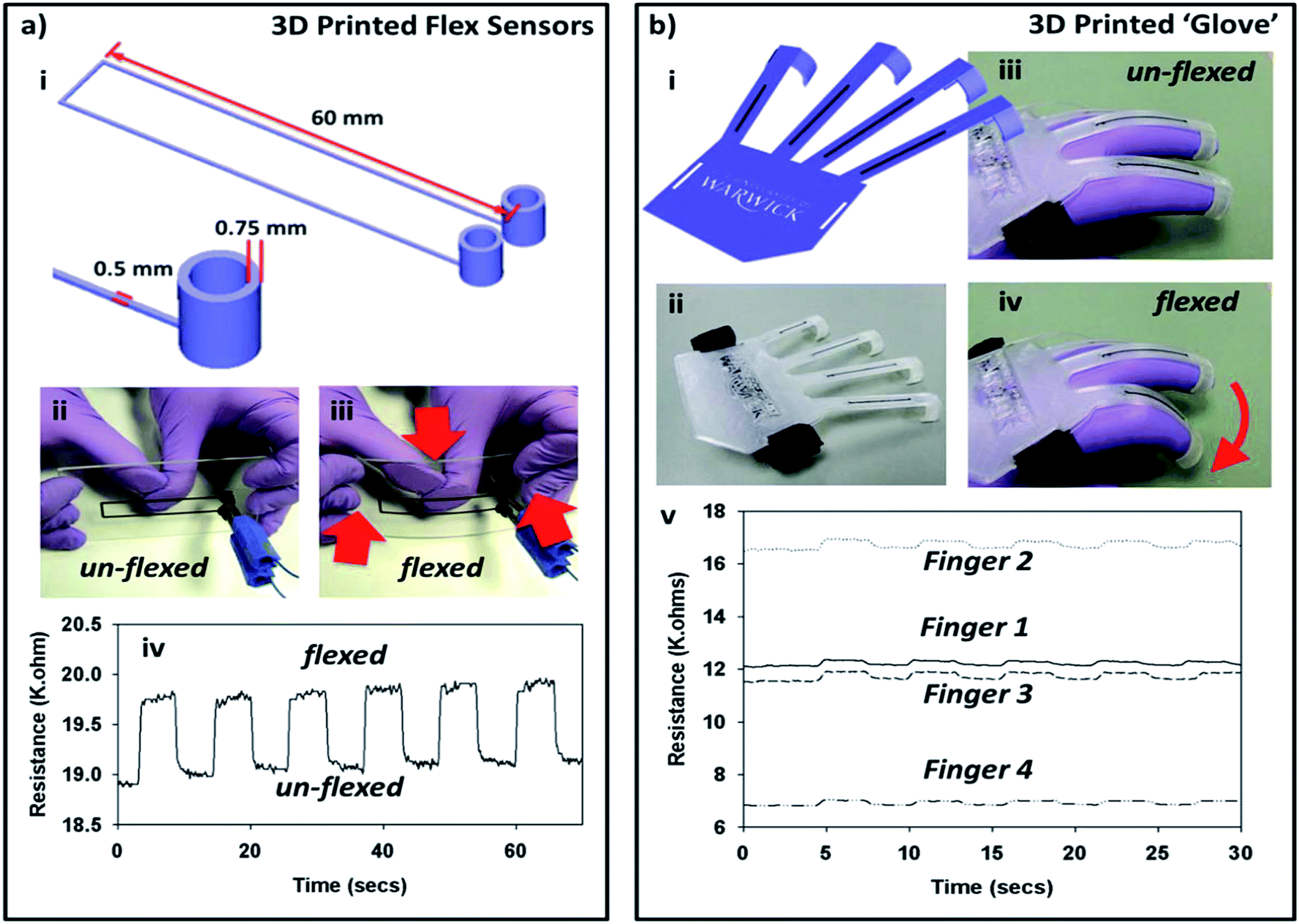 | ||
| Fig. 10 Flex sensor (ai) CAD design, (aii) 3D printed sensor, (aiii) sensor undergoing mechanical stress, (aiv) the resistance response of the sensor during stress. 3D printed glove (bi) CAD design, (bii) 3D printed ‘glove’, (biii) 3D printed ‘glove’ before flexing, (biv) during flexing and (bv) the resistance response of different fingers during flexing. Reproduced with permission.79 | ||
Similarly, Park et al. (2012), developed a conductive composite of elastomers with silver nanoparticles (AgNPs) for creating highly stretchable circuits. To develop the highly flexible circuits the precursor (AgCF3COO and alcohol) for the AgNPs was absorbed in the rubber fibres, followed by formation of AgNPs directly on the fibre mat (see Fig. 11). High bulk conductivity was achieved on percolation of the AgNPs inside the fibre mat and was retained during large deformations. For 3D printing the precursor solution was directly sprayed/nozzle printed on the fibre mat to fabricate both an antenna and light emitting diode with high elasticity, and additionally a strain sensor to demonstrate the potential applications of the developed material.86 The authors claimed the compatibility of the fabrication process with any substrate for the development of arbitrary patterns over a large surface area.
 | ||
| Fig. 11 (a) Schematic illustration of the electrically conductive fibre mat fabrication process. Fibre mat with adsorbed silver precursor (AgCF3COO) and alcohol, and reduction of precursor into AgNP, (b) highly stretch composite AgNP-fibre mat. Reproduced with permission.86 | ||
Recently, Kim et al. (2014) developed a piezoelectric nanoparticle–polymer composite material by introducing barium titanate (BaTiO3, BTO) nanoparticles into polyethylene glycol diacrylate solutions for development of printable sensors, and electronics.87 The 3D printing of graphene composites using the biocompatible elastomer, polylactide-co-glycolide, has also been described for applications in printed electronics and conducting scaffolds. Utilising this liquid composite ink, robust and flexible electrically conducting graphene structures of variable size (as small as 100 μm) and thickness (<300 μm) were realised using extrusion-based 3D printing.76
The fabrication of optically transparent composite conductive films comprised of palladium–copper and silver–copper, printed on a stretchable poly(ethylene terephthalate) (PET) substrates, has also been achieved using inkjet printing. These composite films provided a low cost alternative to indium tin oxide (ITO), an expensive and scarce material, used frequently in the optoelectronic devices. These 3D printed conductive composite films provided minimum resistance and exceptional optical transmittance.88
The coating of printed porous substrates with solutions consisting of conducting filler particles89,90 and injection of electrically conducting solutions into a 3D printed matrix91 is another approach which has been investigated for the production of electrically active composites.89,90 For example, Cooperstein et al. (2015), developed electrically conducting composite objects, again using AgNPs. For development of these conductive composites, porous structures, fabricated using a printable oil-in-water emulsion, were dipped in a dispersion of AgNPs and then sintered at room temperature, to facilitate the development of conductive percolation paths inside the 3D structure.90 Abueidda et al. (2015) similarly prepared interpenetrating phase composites by injecting an electrically conductive solution into the 3D printed matrix with the help of a syringe. The three dimensional ‘reinforcing’ phase was prepared by dispersing carbon nanostructures (0.8 wt%) in to the epoxy resin. The electrical conductivity of the reinforcing phase was reported to be 3.02 × 10⁻² S m−1.91
In addition to introducing conducting fillers into 3D printed structures/scaffolds, efforts have also been made to perform chemical modification of the printed material to render it electrically conductive. For example, Carrico et al. (2015) chemically activated Nafion, a commonly used material for formation of ionic polymer metal composites, to produce electrically active composites. Nafion was printed in its precursor form which is melt processable but electrically inactive. Thus after the precursor polymer has constructed the desired geometry, it is hydrolysed to Nafion to make it electrically conductive. The developed composite material was used for applications in soft robotics.92
There has also been efforts to develop 3D printable dielectric composite materials.93–95 Kurimoto et al. (2015) prepared insulating material by adding alumina to a photo-resin for a stereolithographic (SLA) 3D printer,94 in which the layers of the liquid composite (consisting of filler) are cured via a ultraviolet laser, until the entire structure is fabricated.96 The developed material exhibited high permittivity and low dielectric loss tangent values.94 Similarly, fabrication of dielectric composite materials with relative real permittivities have been achieved by incorporation of BaTiO3 into ABS material for use with FDM printers.95 Isakov et al. (2015) employed a multi extruder FDM based printer to create anisotropic dielectric composites. Two extruders of the printer were loaded with ABS material as the low dielectric permittivity phase and a mixed inorganic ceramic–polymer powder composite material as the high dielectric phase within the final extruder. This approach demonstrated great potential for employing FDM based printers for fabricating novel electromagnetic devices.93
3D printable composite materials with thermal properties
3D printing provides the opportunity to incorporate fillers with high thermal conductivity66,97–100 or insulating properties101 for the fabrication of composites for temperature dependent applications (see Tables 1 and 2 for detailed information on matrix, fillers, composites, their properties and applications). For example, recently a 3D printed graphene–polymer composite has been fabricated by introducing graphene flakes into a commercially available polymer matrix for FDM printing. In this work, graphene was first oxidised to graphene oxide (GO), which was then dispersed in N-methylpyrrolidone (NMP). ABS was then also dissolved in NMP. The two solutions were homogeneously mixed to form GO–ABS dispersion, followed by chemical reduction of GO to develop G–ABS dispersion which was fractionally precipitated via the addition of water (see Fig. 12). The developed G–ABS composite was melted (210 °C) in the FDM 3D printer nozzle, for fabrication of the thermally conducting composites. However, using the FDM process it was not possible to introduce high filler concentrations as formation of graphene aggregates was reported at concentrations at and above 7.4 wt%, which resulted in blocking of the printer nozzle.97 | ||
| Fig. 12 Composite preparation and 3D printing. (a) Graphite flakes, (b and c) dispersions of GO and ABS in NMP solvent, (d and e) a homogeneous mixture of GO–ABS in NMP before and after chemical reduction by hydrazine hydrate at 95 °C for 1 h, (f) G–ABS coagulations obtained after isolation, (e) with water, (g) G–ABS composite powder after washing and drying, (h) schematic illustration of FDM 3D printing process (i) a typical 3D printed model using 3.8 wt% G–ABS composite filament, scale bar: 1 cm. Reproduced with permission.97 | ||
This limitation can be overcome by employing the SLA based printers. In SLA 3D printers, the layers of liquid polymer (including added filler) are photo-cured via the application of an ultraviolet laser,96 therefore avoiding the need for nozzle or spray devices, which are likely to experience recurrent blockages from the added filler. Recently, the thermal and mechanical characteristics of photo-curable resins available for SLA 3D printers has been improved by the addition of TiO2 nanoparticles.98 The composite material showed a significant improvement in tensile strength, 89% in comparison to original polymer. Similar increases in other mechanical properties, including tensile modulus (18%) and flexural (6%) were observed. Differential scanning calorimetry experiments showed improvement in thermal properties by inclusion of the TiO2 nanoparticles in the resin. Very recently, within the authors' own laboratory, Kalsoom et al. (2016), employed a SLA 3D printer for the fabrication of similar composites.99 Using this printer, composite structures consisting of microdiamond particles, at concentrations as high as 30% (w/v) were produced. The developed polymer–diamond composite material was used for the fabrication of both a demonstration heat sink and a cooling system for heat management applications.99 Fig. 13 shows a 3D printed composite heat sink and associated IR images for the composite heat sink and a blank polymer version, when heated at 100 °C for 10 min. As shown the composite material provided increased heat transfer rates in comparison to the blank commercially available epoxy based polymeric material.
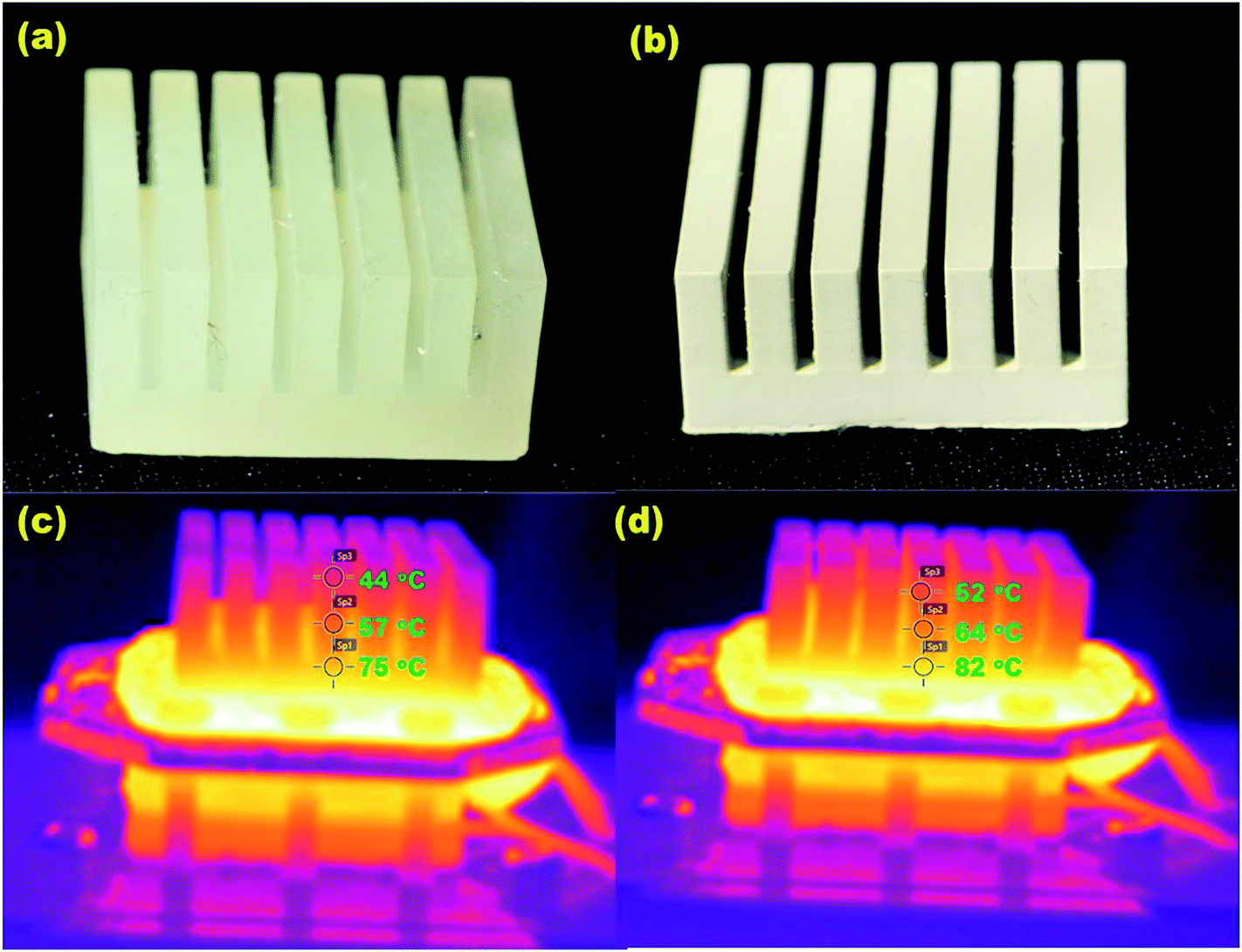 | ||
| Fig. 13 (a) 3D printed heat sink using commercially available polymer, (b) 3D printed heat sink using 30% (w/v) composite material, (c) IR images of polymer heat sink heated for 10 min at 100 °C (d) IR image of composite heat sink heated for 10 min at 100 °C. Reproduced with permission.99 | ||
Besides the development of thermally conducting materials, production of thermoelectric materials with ultra-low thermal conductivities has also been demonstrated for a variety of applications, such as the bionic ear fabrication, reactionware for the chemical sciences, and lithium-ion micro-batteries. For the development of such composite materials, Bi0.5Sb1.5Te3 (BST) powder, a traditional thermoelectric material, was mixed with the photo-curable resin for fabrication of devices using an SLA printer.101
3D printed composite material with enhanced optical properties
Inkjet printing has recently gained much attention as an alternative fabrication method for the manufacturing of electrochromic devices, based upon its ability to rapidly generate high resolution patterns consuming very small quantity of material.102 However, high viscosity and surface tension of the ink causes difficulties in ejecting and preserving the spherical shape of the droplet and therefore presents a major limitation to inkjet printing of electrochromic devices.103,104 However, there has been recent efforts to overcome these limitations via the use of colloidal composites of intrinsically conductive polymers (ICPs), which can decrease the viscosity of high molecular weight polymers in commonly used solvents. For example, the inkjet printing of quantum-dot polymer composites, based upon a colloidal dispersion of quantum dots in polyisobutylene has been employed for the fabrication of patterns of robust luminescent light-converting thin films for AC electroluminescent displays. These quantum dot polymer composites facilitated the inkjet printing of full colour AC driven electroluminescent displays with maximum brightness and minimum power consumption.105 Similarly, Shim et al. (2008) prepared an ICP ink using colloidal composite particles of polyaniline–silica and poly(3,4-ethylenedioxythiophene)–silica for the fabrication of electrochromic devices capable of changing colour depending upon an applied voltage.102 The print deposition of coloured thin films consisting of luminescent colloidal CdSe/ZnS quantum dot (QD)–polymer composites have also been developed. These printed films were also used for fabrication of robust, bright, full-colour AC-driven displays.106Conclusions, challenges and future direction
3D printing technology is significantly contributing to the ongoing revolution in the field of materials science research. The potential of 3D printing for the fabrication of composite material based devices has flung open the doors for a rush of new developments and possibilities in applied material science and is sparking new research into the rapid prototyping of complex objects with unique material properties.However, there are major challenges that still need to be addressed to achieve the full potential of 3D printable composite materials. For example, current commercial 3D printers are designed for relatively simple and often printer specific resins, and not compatible with modified resins, where the inclusion of fillers can cause printer failure, through for example, agglomerate formation, heterogeneous composite formation,5,97 blocking of printer heads, or non-adhesion and increased curing times (e.g. with SLA printing).98,99 There is also the question of printer resolution and the impact of the composite material on such important performance parameters. All of these issues require careful optimisation, however each can be addressed and the achievements detailed within this review are testament to this. It should also be noted that 3D printer companies are beginning to supply commercial composite resins for specific applications and this trend will no doubt now continue at pace, as the diversity of potential materials and composites remains huge.
The ability to precisely control the physical, electrochemical, thermal, and optical properties of 3D complex structures is an exciting thought, and has already gained the attention of all those in the fields of biomedical devices, analytical sciences, fluidics, robotics, the automotive and aerospace industries, printed electronics, to name but a few.
Acknowledgements
This study is financially supported by the ARC Centre of Excellence for Electromaterials Science (ACES) (Grant CE140100012).References
- K. V. Wong and A. Hernandez, ISRN Mech. Eng., 2012, 1–10 CrossRef.
- L. S. Dimas, G. H. Bratzel, I. Eylon and M. J. Buehler, Adv. Funct. Mater., 2013, 23, 4629–4638 CrossRef.
- S. Waheed, J.-M. C. Canyelles, N. Macdonald, R. M. Guijt, T. Lewis, B. Paull and M. C. Breadmore, Lab Chip, 2016, 16, 1993–2013 RSC.
- N. Bhattacharjee, A. Urrios, S. Kanga and A. Folch, Lab Chip, 2016, 16, 1720–1742 RSC.
- O. Ivanova, C. Williams and T. Campbell, Rapid Prototyping J., 2013, 19, 353–364 CrossRef.
- S. Christ, M. Schnabel, E. Vorndran, J. Groll and U. Gbureck, Mater. Lett., 2015, 139, 165–168 CrossRef CAS.
- J. Wang and L. L. Shaw, J. Am. Ceram. Soc., 2006, 89, 3285–3289 CrossRef CAS.
- E. O. Olakanmi, K. W. Dalgarno and R. F. Cochrane, Rapid Prototyping J., 2012, 18, 109–119 CrossRef.
- E. O. Olakanmi, R. F. Cochrane and K. W. Dalgarno, J. Mater. Process. Technol., 2011, 211, 113–121 CrossRef CAS.
- A. Winkel, R. Meszaros, S. Reinsch, R. Muller, N. Travitzky, T. Fey, P. Greil and L. Wondraczek, J. Am. Ceram. Soc., 2012, 95, 3387–3393 CrossRef CAS.
- D. R. Bagal-Kestwal, R. M. Kestwal, W. T. Hsieh and B. H. Chiang, J. Pharm. Biomed. Anal., 2014, 88, 571–578 CrossRef CAS PubMed.
- J. Zhang, S. Zhao, M. Zhu, Y. Zhu, Y. Zhang, Z. Liu and C. Zhang, J. Mater. Chem. B, 2014, 2, 7583–7595 RSC.
- J. Jyoti, S. Basu, B. P. Singh and S. R. Dhakate, Composites, Part B, 2015, 83, 58–65 CrossRef CAS.
- S. Kumar and J. P. Kruth, Mater. Des., 2010, 31, 850–856 CrossRef CAS.
- S. K. Ghosh and P. Saha, Mater. Des., 2011, 32, 139–145 CrossRef CAS.
- Z. Quan, A. Wu, M. Keefe, X. Qin, J. Yu, J. Suhr, J.-H. Byun, B.-S. Kim and T.-W. Chou, Mater. Today, 2015, 18, 503–512 CrossRef CAS.
- R. Detsch, S. Schaefer, U. Deisinger, G. Ziegler, H. Seitz and B. Leukers, J. Biomater. Appl., 2011, 26, 359–380 CrossRef CAS PubMed.
- T. Serra, J. A. Planell and M. Navarro, Acta Biomater., 2013, 9, 5521–5530 CrossRef CAS PubMed.
- G. A. Fielding, A. Bandyopadhyay and S. Bose, Dent. Mater., 2012, 28, 113–122 CrossRef CAS PubMed.
- S. Tarafder, N. M. Davies, A. Bandyopadhyay and S. Bose, Biomater. Sci., 2013, 1, 1250–1259 RSC.
- B. Duan, M. Wang, W. Y. Zhou, W. L. Cheung, Z. Y. Li and W. W. Lu, Acta Biomater., 2010, 6, 4495–4505 CrossRef CAS PubMed.
- J. Deng, P. Li, C. Gao, P. Feng, C. Shuaia and S. Peng, Mater. Manuf. Processes, 2014, 29, 877–884 CrossRef CAS.
- A. Le Duigou, M. Castro, R. Bevan and N. Martin, Mater. Des., 2016, 96, 106–114 CrossRef.
- P. W. Hui, P. C. Leung and A. Sher, J. Biomech., 1996, 29, 123–132 CrossRef CAS PubMed.
- J. M. Taboas, R. D. Maddox, P. H. Krebsbach and S. J. Hollister, Biomaterials, 2003, 24, 181–194 CrossRef CAS PubMed.
- S. E. Bakarich, R. Gorkin III, M. I. H. Panhuis and G. M. Spinks, ACS Appl. Mater. Interfaces, 2014, 6, 15998–16006 Search PubMed.
- H. Seitz, W. Rieder, S. Irsen, B. Leukers and C. Tille, J. Biomed. Mater. Res., Part B, 2005, 74, 782–788 CrossRef PubMed.
- http://www.approto.com/Media-Center/Additive-vs-Subtractive-Manufacturing–Which-is-Ri.aspx, accessed July 2015.
- F. C. Fierz, F. Beckmann, M. Huser, S. H. Irsen, B. Leukers, F. Witte, O. Degistirici, A. Andronache, M. Thie and B. Mueller, Biomaterials, 2008, 29, 3799–3806 CrossRef CAS PubMed.
- S. T. Becker, H. Bolte, O. Krapf, H. Seitz, T. Douglas, S. Sivananthan, J. Wiltfang, E. Sherry and P. H. Warnke, Oral Oncol., 2009, 45, e181–e188 CrossRef PubMed.
- S. Bose, J. Darsell, M. Kintner, H. Hosick and A. Bandyopadhyay, Mater. Sci. Eng., C, 2003, 23, 479–486 CrossRef.
- S. Bose, M. Roy and A. Bandyopadhyay, Trends Biotechnol., 2012, 30, 546–554 CrossRef CAS PubMed.
- J. A. Inzana, D. Olvera, S. M. Fuller, J. P. Kelly, O. A. Graeve, E. M. Schwarz, S. L. Kates and H. A. Awad, Biomaterials, 2014, 35, 4026–4034 CrossRef CAS PubMed.
- H. N. Liu and T. J. Webster, Mater. Sci. Eng., C, 2011, 31, 77–89 CrossRef CAS.
- A. Khalyfa, S. Vogt, J. Weisser, G. Grimm, A. Rechtenbach, W. Meyer and M. Schnabelrauch, J. Mater. Sci.: Mater. Med., 2007, 18, 909–916 CrossRef CAS PubMed.
- K. Igawa, M. Mochizuki, O. Sugimori, K. Shimizu, K. Yamazawa, H. Kawaguchi, K. Nakamura, T. Takato, R. Nishimura, S. Suzuki, M. Anzai, U.-i. Chung and N. Sasaki, J. Artif. Organs, 2006, 9, 234–240 CrossRef CAS PubMed.
- C. Bergmann, M. Lindner, W. Zhang, K. Koczur, A. Kirsten, R. Telle and H. Fischer, J. Eur. Ceram. Soc., 2010, 30, 2563–2567 CrossRef CAS.
- Z. X. Zhou, F. Buchanan, C. Mitchell and N. Dunne, Mater. Sci. Eng., C, 2014, 38, 1–10 CrossRef CAS PubMed.
- C. Shuai, P. Li, J. Liu and S. Peng, Mater. Charact., 2013, 77, 23–31 CrossRef CAS.
- J. L. Davila, M. S. Freitas, P. I. Neto, Z. C. Silveira, J. V. L. Silva and M. A. d'Avila, J. Appl. Polym. Sci., 2016, 133, 9 CrossRef.
- H. Shao, Y. He, J. Fu, D. He, X. Yang, J. Xie, C. Yao, J. Ye, S. Xu and Z. Gou, J. Eur. Ceram. Soc., 2016, 36, 1495–1503 CrossRef CAS.
- S. C. Cox, J. A. Thornby, G. J. Gibbons, M. A. Williams and K. K. Mallick, Mater. Sci. Eng., C, 2015, 47, 237–247 CrossRef CAS PubMed.
- A. Zocca, C. M. Gomes, E. Bernardo, R. Mueller, J. Guenster and P. Colombo, J. Eur. Ceram. Soc., 2013, 33, 1525–1533 CrossRef CAS.
- P. Jeong Hun, J. Jin Woo, K. Hyun-Wook and C. Dong-Woo, Biofabrication, 2014, 6, 025003 CrossRef PubMed.
- D. Puppi, C. Mota, M. Gazzarri, D. Dinucci, A. Gloria, M. Myrzabekova, L. Ambrosio and F. Chiellini, Biomed. Microdevices, 2012, 14, 1115–1127 CrossRef CAS PubMed.
- J.-H. Shim, J.-Y. Won, S.-J. Sung, D.-H. Lim, W.-S. Yun, Y.-C. Jeon and J.-B. Huh, Polymers, 2015, 7, 2061–2077 CrossRef.
- T. N. A. T. Rahim, A. M. Abdullah, H. M. Akil, D. Mohamad and Z. A. Rajion, J. Reinf. Plast. Compos., 2015, 34, 1628–1638 CrossRef.
- M. Zhu, S. Zhao, C. Xin, Y. Zhu and C. Zhang, Biomater. Sci., 2015, 3, 1236–1244 RSC.
- J. Visser, F. P. W. Melchels, J. E. Jeon, E. M. van Bussel, L. S. Kimpton, H. M. Byrne, W. J. A. Dhert, P. D. Dalton, D. W. Hutmacher and J. Malda, Nat. Commun., 2015, 6, 1–10 Search PubMed.
- S. Agila and J. Poornima, Magnetically controlled nano-composite based 3D printed cell scaffolds as targeted drug delivery systems for cancer therapy, Proceedings of the 15th IEEE International Conference on Nanotechnology, Rome, Italy, July, 2015 Search PubMed.
- J.-H. Shim, M.-J. Kim, J. Y. Park, R. G. Pati, Y.-P. Yun, S. E. Kim, H.-R. Song and D.-W. Cho, Tissue Eng. Regener. Med., 2015, 12, 283–293 CrossRef CAS.
- F. Ning, W. Cong, J. Qiu, J. Wei and S. Wang, Composites, Part B, 2015, 80, 369–378 CrossRef CAS.
- B. G. Compton and J. A. Lewis, Adv. Mater., 2014, 26, 5930–5935 CrossRef PubMed.
- K. C. Chuang, J. E. Grady and R. D. Draper, Additive manufacturing and characterisation of Ultem polymers and composites, CAMX – The Composites and Advanced Materials Expo, Dallas, TX, October, 2015 Search PubMed.
- R. D. Goodridge, M. L. Shofner, R. J. M. Hague, M. McClelland, M. R. Schlea, R. B. Johnson and C. J. Tuck, Polym. Test., 2011, 30, 94–100 CrossRef.
- R. Matsuzaki, M. Ueda, M. Namiki, T.-K. Jeong, H. Asahara, K. Horiguchi, T. Nakamura, A. Todoroki and Y. Hirano, Sci. Rep., 2016, 6, 23058 CrossRef PubMed.
- W. Kuczko, R. Wichniarek, F. Gorski, P. Bun and P. Zawadzki, Adv. Sci. Technol. Res. J., 2015, 9, 20–27 CrossRef.
- U. Scheithauer, A. Bergner, E. Schwarzer, H.-J. Richter and T. Moritz, J. Mater. Res., 2014, 29, 1931–1940 CrossRef.
- D. Lin, S. Jin, F. Zhang, C. Wang, Y. Wang, C. Zhou and G. J. Cheng, Nanotechnology, 2015, 26, 1–9 CAS.
- D. W. Lipke, Y. Zhang, Y. Liu, B. C. Church and K. H. Sandhage, J. Eur. Ceram. Soc., 2010, 30, 2265–2277 CrossRef CAS.
- Y. Ma, X. Yin, X. Fan, L. Wang, P. Greil and N. Travitzky, Int. J. Appl. Ceram. Technol., 2015, 12, 71–80 CrossRef CAS.
- J. J. Martin, B. E. Fiore and R. M. Erb, Nat. Commun., 2015, 6, 8641 CrossRef PubMed.
- J. Wilkes, Y.-C. Hagedorn, W. Meiners and K. Wissenbach, Rapid Prototyping J., 2013, 19, 51–57 CrossRef.
- K. G. Jaya Christiyan, U. Chandrasekhar and K. Venkateswarlu, Presented in Part at the IOP Conference Series: Materials Science and Engineering, 2016 Search PubMed.
- K. P. Cai, J. B. Sun, Q. Li, R. Wang, B. Li and J. Zhou, Appl. Phys. A: Mater. Sci. Process., 2011, 102, 501–507 CrossRef CAS.
- C. Huang, G. Jian, J. B. DeLisio, H. Wang and M. R. Zachariah, Adv. Eng. Mater., 2015, 17, 95–101 CrossRef CAS.
- J. O. Hardin, T. J. Ober, A. D. Valentine and J. A. Lewis, Adv. Mater., 2015, 27, 3279–3284 CrossRef PubMed.
- S. H. Ahn, K. T. Lee, H. J. Kim, R. Wu, J. S. Kim and S. H. Song, Int. J. Precis. Eng. Manufact., 2012, 13, 631–634 CrossRef.
- X. Zhi, H. B. Zhang, Y. F. Liao, Q. H. Hu, C. X. Gui and Z. Z. Yu, Carbon, 2015, 82, 195–204 CrossRef CAS.
- N. George, J. C. S. Chandra, A. Mathiazhagan and R. Joseph, Compos. Sci. Technol., 2015, 116, 33–40 CrossRef CAS.
- B. Roman-Manso, F. M. Figueiredo, B. Achiaga, R. Barea, D. Perez-Coll, A. Morelos-Gomez, M. Terrones, M. Isabel Osendi, M. Belmonte and P. Miranzo, Carbon, 2016, 100, 318–328 CrossRef CAS.
- S. Duan, K. Yang, Z. Wang, M. Chen, L. Zhang, H. Zhang and C. Li, ACS Appl. Mater. Interfaces, 2016, 8, 2187–2192 Search PubMed.
- S.-z. Guo, X. Yang, M.-C. Heuzey and D. Therriault, Nanoscale, 2015, 7, 6451–6456 RSC.
- C. M. Shemelya, A. Rivera, A. T. Perez, C. Rocha, M. Liang, X. Yu, C. Kief, D. Alexander, J. Stegeman, H. Xin, R. B. Wicker, E. MacDonald and D. A. Roberson, J. Electron. Mater., 2015, 44, 2598–2607 CrossRef CAS.
- C. R. Rambo, N. Travitzky and P. Greil, J. Compos. Mater., 2015, 49, 1971–1976 CrossRef CAS.
- A. E. Jakus, E. B. Secor, A. L. Rutz, S. W. Jordan, M. C. Hersam and R. N. Shah, ACS Nano, 2015, 9, 4636–4648 CrossRef CAS PubMed.
- C. Yang, X. Cui, Z. Zhang, S. W. Chiang, W. Lin, H. Duan, J. Li, F. Kang and C.-P. Wong, Nat. Commun., 2015, 6, 8150 CrossRef PubMed.
- W. R. Small and M. in het Panhuis, Small, 2007, 3, 1500–1503 CrossRef CAS PubMed.
- S. J. Leigh, R. J. Bradley, C. P. Purssell, D. R. Billson and D. A. Hutchins, PLoS One, 2012, 7, e49365 CrossRef CAS PubMed.
- M. in het Panhuis, A. Heurtematte, W. R. Small and V. N. Paunov, Soft Matter, 2007, 3, 840–843 RSC.
- K. Kordas, T. Mustonen, G. Toth, H. Jantunen, M. Lajunen, C. Soldano, S. Talapatra, S. Kar, R. Vajtai and P. M. Ajayan, Small, 2006, 2, 1021–1025 CrossRef CAS PubMed.
- G. Postiglione, G. Natale, G. Griffini, M. Levi and S. Turri, Composites, Part A, 2015, 76, 110–114 CrossRef CAS.
- B. S. Shim, W. Chen, C. Doty, C. L. Xu and N. A. Kotov, Nano Lett., 2008, 8, 4151–4157 CrossRef CAS PubMed.
- A. R. Madaria, A. Kumar and C. Zhou, Nanotechnology, 2011, 22, 245201 CrossRef PubMed.
- S. R. Athreya, K. Kalaitzidou and S. Das, Mater. Sci. Eng., A, 2010, 527, 2637–2642 CrossRef.
- M. Park, J. Im, M. Shin, Y. Min, J. Park, H. Cho, S. Park, M.-B. Shim, S. Jeon, D.-Y. Chung, J. Bae, J. Park, U. Jeong and K. Kim, Nat. Nanotechnol., 2012, 7, 803–809 CrossRef CAS PubMed.
- K. Kim, W. Zhu, X. Qu, C. Aaronson, W. R. McCall, S. Chen and D. J. Sirbuly, ACS Nano, 2014, 8, 9799–9806 CrossRef CAS PubMed.
- M. Mohl, A. Dombovari, R. Vajtai, P. M. Ajayan and K. Kordas, Sci. Rep., 2015, 5, 13710 CrossRef PubMed.
- K. Chi, Z. Zhang, J. Xi, Y. Huang, F. Xiao, S. Wang and Y. Liu, ACS Appl. Mater. Interfaces, 2014, 6, 16312–16319 Search PubMed.
- I. Cooperstein, M. Layani and S. Magdassi, J. Mater. Chem. C, 2015, 3, 2040–2044 RSC.
- D. W. Abueidda, R. K. Abu Al-Rub, A. S. Dalaq, H. A. Younes, A. A. Al Ghaferi and T. K. Shah, Compos. Sci. Technol., 2015, 118, 127–134 CrossRef CAS.
- J. D. Carrico, N. W. Traeden, M. Aureli and K. K. Leang, Smart Mater. Struct., 2015, 24, 125021–125031 CrossRef.
- D. V. Isakov, Q. Lei, F. Castles, C. J. Stevens, C. R. M. Grovenor and P. S. Grant, Mater. Des., 2016, 93, 423–430 CrossRef CAS.
- M. Kurimoto, Y. Yamashita, H. Ozaki, T. Kato, T. Funabashi and Y. Suzuoki, in 2015 IEEE Conference on Electrical Insulation and Dielectric Phenomena, 2015, pp. 463–466 Search PubMed.
- F. Castles, D. Isakov, A. Lui, Q. Lei, C. E. J. Dancer, Y. Wang, J. M. Janurudin, S. C. Speller, C. R. M. Grovenor and P. S. Grant, Sci. Rep., 2016, 6, 22714 CrossRef CAS PubMed.
- B. C. Gross, J. L. Erkal, S. Y. Lockwood, C. Chen and D. M. Spence, Anal. Chem., 2014, 86, 3240–3253 CrossRef PubMed.
- X. Wei, D. Li, W. Jiang, Z. Gu, X. Wang, Z. Zhang and Z. Sun, Sci. Rep., 2015, 5, 1–7 Search PubMed.
- Y. Duan, Y. Zhou, Y. Tang and D. Li, Rapid Prototyping J., 2011, 17, 247–252 CrossRef.
- U. Kalsoom, P. N. Nesterenko and B. Paull, RSC Adv., 2016, 6, 38140–38147 RSC.
- S. Hwang, E. I. Reyes, K.-S. Moon, R. C. Rumpf and N. S. Kim, J. Electron. Mater., 2015, 44, 771–777 CrossRef.
- M. He, Y. Zhao, B. Wang, Q. Xi, J. Zhou and Z. Liang, Small, 2015, 11, 5889–5894 CrossRef PubMed.
- G. H. Shim, M. G. Han, J. C. Sharp-Norton, S. E. Creager and S. H. Foulger, J. Mater. Chem., 2008, 18, 594–601 RSC.
- B. J. de Gans, P. C. Duineveld and U. S. Schubert, Adv. Mater., 2004, 16, 203–213 CrossRef CAS.
- P. Calvert, Chem. Mater., 2001, 13, 3299–3305 CrossRef CAS.
- E. Tekin, P. J. Smith, S. Hoeppener, A. M. J. v. d. Berg, A. S. Susha, A. L. Rogach, J. Feldmann and U. S. Schubert, Adv. Funct. Mater., 2007, 17, 23–28 CrossRef CAS.
- V. Wood, M. J. Panzer, J. Chen, M. S. Bradley, J. E. Halpert, M. G. Bawendi and V. Bulovic, Adv. Mater., 2009, 21, 1–5 Search PubMed.
- M. Zhu, J. Zhang, S. Zhao and Y. Zhu, J. Mater. Sci., 2016, 51, 836–844 CrossRef CAS.
- J. Suwanprateeb, R. Sanngam, W. Suvannapruk and T. Panyathanmaporn, J. Mater. Sci.: Mater. Med., 2009, 20, 1281–1289 CrossRef PubMed.
- K. Lee, C.-R. Seo, J.-M. Ku, H. Lee, H. Yoon, J. Lee, W. Chun, K. W. Park and G. Kim, RSC Adv., 2015, 5, 29335–29345 RSC.
- G. Tsiakatouras, E. Tsellou and C. Stergiou, World Transactions on Engineering and Technology Education, 2014, 12, 392–396 Search PubMed.
- S. Ahn, J. Y. Hong, M. K. Hong, Y. P. Jang, M. S. Oh, J. H. Jung and J. Hong, Rapid Commun. Mass Spectrom., 2009, 23, 3158–3166 CrossRef PubMed.
| This journal is © The Royal Society of Chemistry 2016 |