
 Open Access Article
 This Open Access Article is licensed under a Creative Commons Attribution-Non Commercial 3.0 Unported Licence
Spatial and temporal patterning of polymers in electric field responsive LC templates†
Pim
van der Asdonk
 ,
Hans C.
Hendrikse
,
Atang C.
Sauli
,
Stijn P. M.
Kraaijkamp
and
Paul H. J.
Kouwer
*
,
Hans C.
Hendrikse
,
Atang C.
Sauli
,
Stijn P. M.
Kraaijkamp
and
Paul H. J.
Kouwer
*
Department of Molecular Materials, Institute for Molecules and Materials, Radboud University, Heyendaalseweg 135, 6525 AJ Nijmegen, The Netherlands. E-mail: p.kouwer@science.ru.nl
First published on 12th August 2016
Abstract
Controlling the spatial and temporal organization of functional polymers is essential for the development of switchable soft-matter based electro-optical devices. By using a combination of a liquid crystal template, a photopatternable substrate (for spatial control) and electric fields (for dynamically switching) we show that we are able to dynamically control the spatial organization of polymers across multiple length scales (conveyed through the patterned liquid crystal template). The polymer that we organize is an azobenzene-functionalized polyisocyanide, whose stiff polymeric helix and laterally attached pendant azobenzene units induce tangential anchoring to the liquid crystal host. Due to the donor–acceptor functionalized azobenzene units, the polymeric material is strongly absorbing in the visible range for characterization purposes. We find that polymers align locally to the liquid crystal director field and reversibly change its orientation by the application of an electric field. Since this hybrid technique can be easily applied to other functional polymeric materials and relies on simple techniques, such as spincoating, photoalignment and electric fields, we believe it has great potential for the development of a wide range of switchable electro-optical devices.
Introduction
Polymeric materials form the basis of a wide range of technological applications. Their properties can be tailored by changing the molecular structure and backbone architecture. In addition, they are commonly easy to process and often cheap. Despite containing a well-defined (macro)molecular structure, at larger length scales polymeric materials are isotropic. For many applications this is no problem, but other applications strongly benefit from high structural definition at multiple length scales. To boost device performance, a number of techniques have been developed that address macroscopic length scales, including photo and soft lithography, electrospinning and the application of electric, magnetic or mechanical fields. Many of these techniques however, are not suited for both designing complex patterns, nor can they dynamically manipulate the polymer orientation after alignment/pattern formation. Such functionalities are critical for the development of switchable soft-matter based optical and electric applications.1In this manuscript, we use liquid crystal templating (LCT) to generate complex and dynamic structures of polymer materials. LCT has been successfully applied to organize various soft materials in bulk liquid crystals. Key examples include supramolecular aggregates,2,3 (semi)conducting organic polymers,4–9 and carbon nanotubes.10–12 To a lesser extent, this approach has been applied to aqueous lyotropic or chromonic templates, for example to organize carbon nanotubes,13,14 motile bacteria,15–17 and a spatially patterned chromonic–silica hybrid18 and self-assembled peptide amphiphiles,19 both on photopatternable substrates. The major advantages of LCT are its versatility, its high dimensional control and its dynamic addressability. The versatility stems from the absence of distinct molecular interactions between the template and the polymer. Dimensional control is given by the substrate; micrometer patterning techniques are already commercially applied in the LCD industry.20 Lastly, the liquid crystal template is readily manipulated using electric fields, again analogous to LCD technology, which introduces spatially controlled dynamics to the dispersed polymers. The promises of LCT has only partly been realized: by far the majority of studies are focused on plain long-range unidirectional alignment and only rare examples use complex structured substrates18,19 or electric fields4,8,10–12 to take full advantage of this approach.
In this paper, we use an approach to spatially and temporally control the organization of functional polymers, by applying a combination of a liquid crystal template, a photopatternable substrate and electric fields. This is to our knowledge the first example where both complex patterned in-plane alignment of functional polymers is obtained, combined with controlled reversible homeotropic switching of these materials.
In order to benefit from the anisotropic environment that the liquid crystalline matrix offers, one would like to use rigid or semi-flexible polymers with a persistence length larger or of the same order as the contour length. Polyisocyanides are such class of polymers through the formation of a rigid helix which is the result of the polymerization mechanism. The helical backbone conformation, supported by a β-sheet-like hydrogen-bond pattern at the periphery yields stiff polymer chains,21 which can be decorated by a variety of functional groups.22 We used an azobenzene-functionalized polyisocyanide (AzoPIC). The azobenzene units increase solubility of the monomer (and polymer) in the liquid crystal and are laterally attached to induce tangential anchoring in the liquid crystal host. Although we designed the polymer for optimal compatibility with the liquid crystal host, the strength of liquid crystal templating is that no specific molecular interactions with the host are necessary to achieve the desired alignment.4,8,12 Furthermore, the azobenzene units carry donor and acceptor groups to push the absorbance deep into the visible for characterization purposes. We find that polymers align locally to the liquid crystal director field and reversibly change its orientation by the application of an electric field. Moreover, we find that for its assemblies also intermediate alignment can be realized.
Materials and methods
Polyisocyanides (PICs) are a class of long, helical and rigid polymers. The approximate 41 helical backbone conformation, which is the result of the polymerization mechanism, is stabilized through β-sheet like hydrogen bonding between adjacent peptide groups.23 Earlier work in our group used the polymer as a rigid scaffold to precisely control the architecture of substituted chromophores, including D–π–A-based azobenzenes, which showed to have tremendous dipole moments.24 Its intrinsic structural stiffness and molecular anisotropy makes PICs very responsive to elastic force alignment via LCT. To induce planar alignment of the surrounding liquid crystal host, we introduced mesogen-like substituents that were laterally grafted through a short spacer. To separate the absorbance of the AzoPIC (low concentration) from the 5CB liquid crystal (high concentration), we further introduced donor and acceptor groups on the chromophore. The structure and a sketch of the helical conformation are displayed in Fig. 1.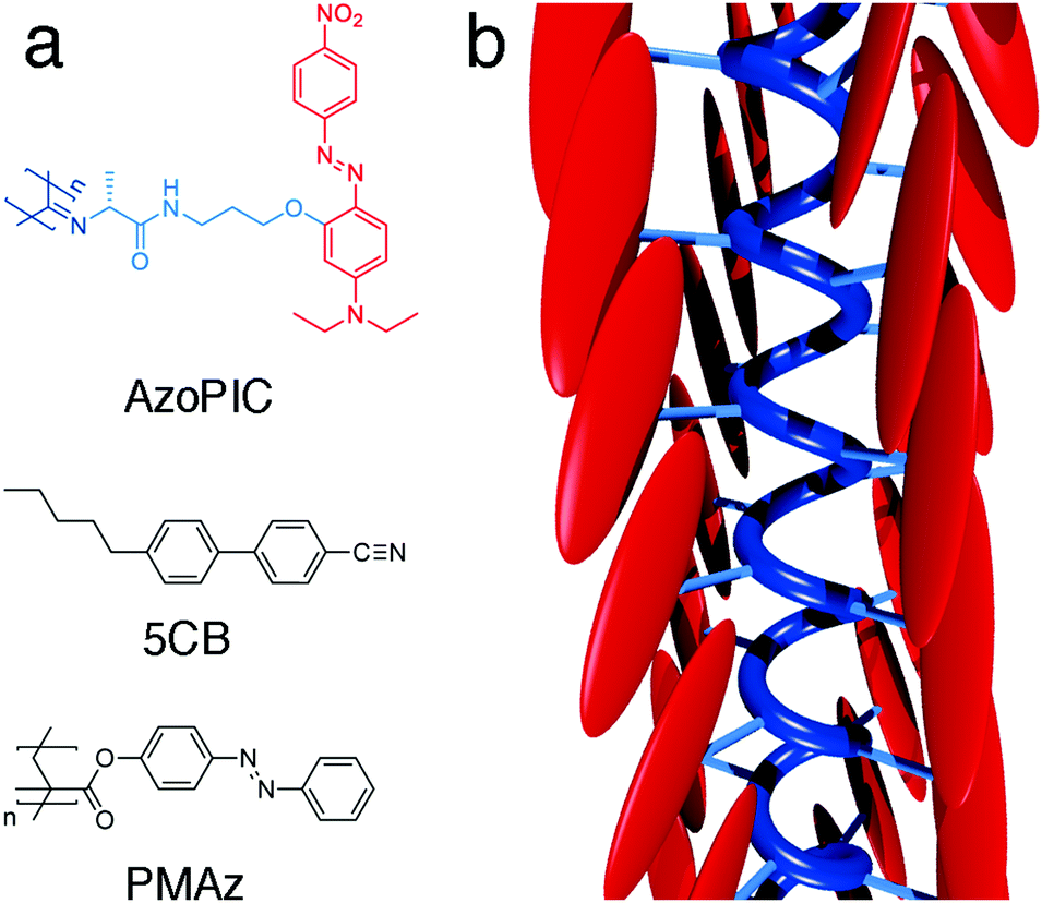 | ||
| Fig. 1 Molecular structures (a) of AzoPIC, LC template 5CB and command layer material PMAz. Schematic 3D depiction (b) of AzoPIC. | ||
The synthesis of AzoPIC is outlined in Scheme 1. Details of the synthesis and characterization are given in the ESI.† Boc-protected alanine was equipped with a short spacer through a standard EDC coupling reaction. The hydroxyl-functionalized push–pull azobenzene252 was first deprotonated with t-BuOK and then added to bromide 1 to give the functionalized boc-protected alanine 3. Deprotection with EtOAc·HCl, formylation and dehydration using Burgess' reagent yielded the isocyanide monomer 5 in an 18% overall yield. The polymerization of monomer 5 was initiated with a Ni2+ salt in the presence of a small amount of alcohol. The reaction was carried out in chloroform (which is common solvent for isocyanide polymerization reactions) or in 4-cyano-4′-pentyl-1,1′-biphenyl (5CB). In 5CB, the monomer concentration studied was relatively low (c = 0.035 wt%), due to the limited solubility of 5 in this liquid crystal (0.064 wt%).
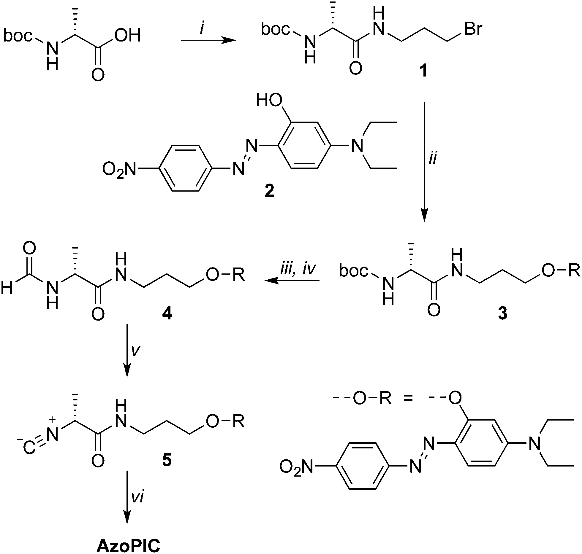 | ||
Scheme 1 Synthesis of AzoPIC. Key: (i) 3-bromo-1-aminopropane hydrobromide, N,N-diisopropylethylamine, N-hydroxybenzotriazole, 1-ethyl-3-(3-dimethylaminopropyl)carbodiimide, CH2Cl2, room temperature, 24 h, 58%; (ii) potassium tert-butoxide, DMF, 0 to 100 °C, 16 h, 46%; (iii) 2.3 M HCl in EtOAc, room temperature, 2 h, yield not determined; (iv) sodium formate, ethyl formate, 60 °C, 48 h, 82%; methyl N-(triethylammoniumsulfonyl)carbamate, CH2Cl2, reflux, 5 h, 80%; (vi) nickel perchlorate in toluene/EtOH (98![[thin space (1/6-em)]](https://www.rsc.org/images/entities/char_2009.gif) :2), CHCl3 or 5CB, >24 h, room temperature. :2), CHCl3 or 5CB, >24 h, room temperature. | ||
As for the liquid crystal template, we used the liquid crystal workhorse 4-cyano-4′-pentylbiphenyl (5CB, Fig. 1), which forms a nematic LC phase at room temperature. This well-studied thermotropic liquid crystal has also been applied in several organic LCT examples3,9–11,26 and is highly susceptible to electric fields due to its dipolar molecular structure and typical long range cooperative interactions. Furthermore, its biphenyl aromatic core is anticipated to have favorable interactions with the azobenzene side groups of AzoPIC.
The photopatternable command layer is an azobenzene-functionalized polymethacrylate (PMAz, Fig. 1); its synthesis and characterization were described earlier.19 By using simple procedures based on multiple illumination steps with polarized light and photomasks, micron-scale patterns of locally aligned azobenzenes (covalently attached to a PMA matrix) can be imprinted on a wide range of substrates.27,28 This locally patterned PMAz command layer transfers the organization to many bulk liquid crystals. Since PMAz is applied to a substrate by spincoating, we can easily coat conducting ITO/glass substrates (CEC100S, PGO), which allows for the application of electric fields and can ultimately be integrated with standard pixel-based LCD technology. In our study we constructed ∼1 cm2 20 μm spaced liquid crystal cells from the PMAz-coated ITO plates.
Results and discussion
Full spatial control
For the isocyanide polymerization reaction, we prepared a solution of isocyanide monomer 5 (0.035 wt% in 5CB) which was stirred for 4 days to ensure complete dissolution of the monomer. A part of this solution was set aside and used as a control sample. An amount of the solution was mixed with the nickel(II) perchlorate catalyst solution, such that the catalyst/monomer ratio was 1:500. This polymerizing mixture was introduced into a number of liquid crystal cells (see below) to follow the progress of the reaction with (polarized) optical microscopy. The remainder was polymerized in a reaction tube and followed with spectroscopic tools.
Polymer formation is best followed with circular dichroism (CD). Whilst the isocyanide monomer 5 is CD silent (like many chromophore-substituted isocyanides), the polymer shows a Cotton effect right at the absorption wavelength of the azobenzene side groups (Fig. 2). This is a clear indication that in the AzoPIC polymer, the chromophores are stacked in a helical configuration along the polymer backbone.29 The reaction proceeds slowly due to the low concentration of monomer and catalyst. The yield of the isocyanide polymerization reaction, often measured by disappearance of the characteristic isocyanide stretch in IR spectroscopy was not determined as the large number of cyano groups of the liquid crystal template obstructed quantification. The very small amounts of polymer (approximately 0.5 ng per cell) impeded other standard polymer characterization techniques, such as molecular weight analysis. Following the formation of AzoPIC in chloroform did show the disappearance of the isocyanide stretch (Fig. S1, ESI†). Both 5 and AzoPIC have a slight influence on the thermal properties of the liquid crystalline matrix; the presence of these compounds in both situations lowers the nematic–isotropic transition temperature TNI of 5CB by 0.3 °C.
 | ||
| Fig. 2 Circular dichroism (top) and UV-vis (bottom) spectra of 5 in 5CB before (blue) and after (red) adding catalyst solution. The solutions were diluted 6-fold with p-xylene to remove signal scattering induced by the nematic 5CB and to reduce the overall strong absorption of solution. | ||
For the microscopy studies, we introduced the polymerizing mixtures in two types of cells: standard parallel-rubbed polyimide (PI)-coated glass cells and custom-made photopatterned cells (detailed information about the sample and cell preparation can be found in the ESI†). The latter were prepared by spin coating a thin layer of PMAz on an electrode (indium tin oxide, ITO) covered glass substrate and patterning the PMAz layers in following three consecutive irradiations steps (with three different polarization directions) using a photomask designed after the logo of our IMM institute (Fig. S2, ESI†). After filling the cells, we observed that the LC locally aligned with respect to the patterned command layer (Fig. 2a), where the direction of the 5CB mesogens is parallel to the photoaligned azobenzene moieties of PMAz (Fig. S3, ESI†). After a few hours, we observed the formation of micron-sized red colored bundles aligned parallel to the local LC director (Fig. 2b and c). Control samples with 5 in 5CB without catalyst present in rubbed polyimide (Fig. S4, ESI†) or photopatterned PMAz (Fig. S5, ESI†) cells did not show any sign of the formation of (aligned) red bundles. After several days, a parallel-rubbed polyimide cell with 5/5CB/catalyst solution was carefully opened, the LC was washed away and scanning electron microscopy (SEM) showed small bundles organized on the substrate in the rubbing direction (Fig. 3d).
 | ||
| Fig. 3 Directed orientation of AzoPIC bundles by a 5CB template in a photopatterned PMAz cell (20 μm spacing). Polarized optical microscopy (POM) image (a and b) of a mixture of isocyanide monomer 5 (0.035 wt%), 5CB and catalyst solution, a few hours after capillary insertion in a photopatterned PMAz ITO/glass cell. Photopatterning yielded domains with three different orientations, as indicated by the light-blue double-sided arrows. Panel (b) is a zoom from panel (a). The corresponding optical microscopy (OM) image (c) shows bundles of AzoPIC aligned to the local nematic director, parallel to the polarization direction. The thin black line that indicates the boundary between the photopatterned domains was added for visual clarity. The OM image was taken after removing the analyzer from the POM stage, whilst leaving the polarizer in the orientation given by the white double-sided arrow. The polarizer enhances the contrast of the bundled structures with the background (due to its strong dichroic properties), thus improves the general visibility of the bundles. After cell opening and removal of the template, SEM (d) shows bundles (assembled in a 5CB template) on rubbed polyimide aligned in the same direction as the rubbing direction (vertical). | ||
The approx. 10 μm long structures are obviously longer and wider than single polyisocyanide chains and we expect them to be bundles of chains. These bundles are formed as a result of depletion interactions (which depend on time, temperature and the AzoPIC length and concentration) between the anisotropic LC solvent and 1D AzoPIC. Fig. 3c shows that the 5CB background however, is also still colored. This red shade originates from AzoPIC that is molecularly dissolved or in very small (microscopically invisible) bundles, or may come from unreacted isocyanide monomer as a result of the incomplete polymerization reaction. Further microscopy studies with polarized light showed that the red color is, in fact, polarization dependent and thus also aligns with the 5CB matrix (see backgrounds in Fig. 4).
 | ||
| Fig. 4 Anisotropic absorption characteristics of locally unidirectionally aligned AzoPIC bundles on a photopatterned PMAz cell (20 μm spacing). AzoPIC bundles clearly show strong absorption characteristics when the polarizer is oriented parallel to the bundle direction (indicated by the white double-sided arrow). Note when the polarizer is oriented perpendicular to the bundle direction that the AzoPIC bundles are almost invisible. For visual clarity, the thin black line indicates the boundary between the photopatterned domains. | ||
The AzoPIC bundles, which are locally aligned to the template show strong linear polarized absorption characteristics. In Fig. 4, the polarization of the light source is rotated 360° in four 90° steps. When the polarizer is directed parallel to the anisotropic AzoPIC bundles, the bundles appear dark (Fig. 4a and b), caused by the strong absorbance of the D–π–A azobenzene dyes grafted on the polymer backbone. While rotating the polarizer perpendicular to the bundles, they become almost indistinguishable from their background as the absorbance is minimal (Fig. 4c and d). The azobenzene's main absorption band (at λmax = 497 nm) is attributed to the π–π* transition. The corresponding dipole moment (along the long axis of the molecule) thus is oriented parallel to the director of the 5CB LCT. This also means that the attached azobenzene moieties are oriented largely parallel to the PIC backbone, as is schematically represented in Fig. 1. The orientation of monomer, dissolved polymer and or small bundles follows the same trend and here the dyes are also oriented parallel to the director (see for instance in the backgrounds of the top areas of Fig. 4, panels a and c or the bottoms of panels b and d).
Electric field switching
After micro-structuring the AzoPIC (assemblies) on the photopatterned PMAz command layer, we applied a homeotropic AC electric field (20 V, 1 V μm−1, 1 MHz) to the PMAz cells to dynamically switch the polymers. Fig. 5 and Movie S1 (ESI†) both show the reversible reorientation of the locally organized AzoPIC bundles in the 5CB LCT when a homeotropic electric field is applied. Fig. 5a shows two domains with the nematic directors parallel (top) and oriented 45° (bottom) with respect to the polarizer (white double-sided arrow), which are separated by a thin black line. Before applying the field, the AzoPIC bundles are aligned in-plane within each corresponding domain. Directly after applying the field, 5CB immediately reorients homeotropically due to the electric field induced Freedericksz transition (Fig. S6, ESI†),30 where the patterned domains are now clearly separated by a defect line.31 The AzoPIC bundles also undergo an in-plane to homeotropic reorientation (Fig. 5b), but much slower; after several seconds the bundles are fully rotated in the homeotropic direction (Fig. 5c). When switching off the field, the bundles slowly reorient due to the in-plane realigned bulk LCT (Fig. 5d). Again, after several seconds the bundles are completely realigned in the planar orientation within their respective 5CB domain (Fig. 5e). We believe elastic forces induced by the LC to be responsible for the realignment of these bundles when the bulk LCT changes its orientation with respect to the electric field, analogous to earlier examples where LCT and electric fields were applied to both dispersed carbon nanotubes12 and polymeric nanowires.8 | ||
| Fig. 5 In-plane patterned AzoPIC bundle switching through a homeotropic electric field reorienting 5CB template. Before the field (0.43 V μm−1, 1 MHz) is turned on (a) AzoPIC bundles (encircled) are aligned in plane within their respective domain, where the interface for visual clarity is indicated by the dashed black line. The direction of the 5CB within the two different domains is indicated by the light-blue double-sided arrows. As soon as the field is turned on (b) the AzoPIC bundles slowly rotate, until roughly after 5 seconds they are aligned homeotropically (c). Roughly between the domains a defect line appears, due to the interfacial region between domains of strongly anchored in-plane aligned 5CB mesogens very close to the surface. When turning off the field, the AzoPIC bundles start to rotate (d) until they lie in-plane within their domain. In panel (a–e), one specific section containing an AzoPIC bundle has been enlarged for improved visibility purposes. Panel (f) shows the dependency of AzoPIC bundle length in relation to both its in-plane to homeotropic switching time (after switching the electric field on) and homeotropic to in-plane relaxation time (after switching the field off). The electric field was switched on and off three consecutive times. The switching time was measured as the time it took for the bundle to rotate 90% of its length. The error bars indicate the standard deviation over three measurements. | ||
Through POM analysis, we quantitatively determined the switching times of the AzoPIC bundles in relation to their bundle length (Fig. 5f) by measuring the response rates of a number of individual bundles of different sizes. As could be expected based on their inertia, for smaller bundles the switching times are shorter while larger bundles respond slower. For the longest bundles, we anticipate that the bundles interact with the substrate, which can contribute to the observed slower in-plane to homeotropic transition. The response rate of the bundles is of the order of seconds, much slower than the polymer PFO nanowires in prepared the nematic host E7, for which 100 ms response times were recorded.8 The latter one-dimensional structures were smaller (2 μm) and were switched at a slightly higher electric field (0.6 V μm−1).
From the POM analysis, we also were able to measure the change in orientation of an AzoPIC bundle as a function of the field strength (Fig. 6). After a threshold field of approximately 0.05 V μm−1, the 14 μm long AzoPIC bundle rotates from an in-plane orientation into a complete homeotropic orientation at 0.43 V μm−1. At intermediate electric field strengths (between 0.1 and 0.43 V μm−1), the bundle adopts a stable partially rotated alignment where the degree of reorientation is related to the applied field. We find that this electric field range also depends on the length of the specific bundle.
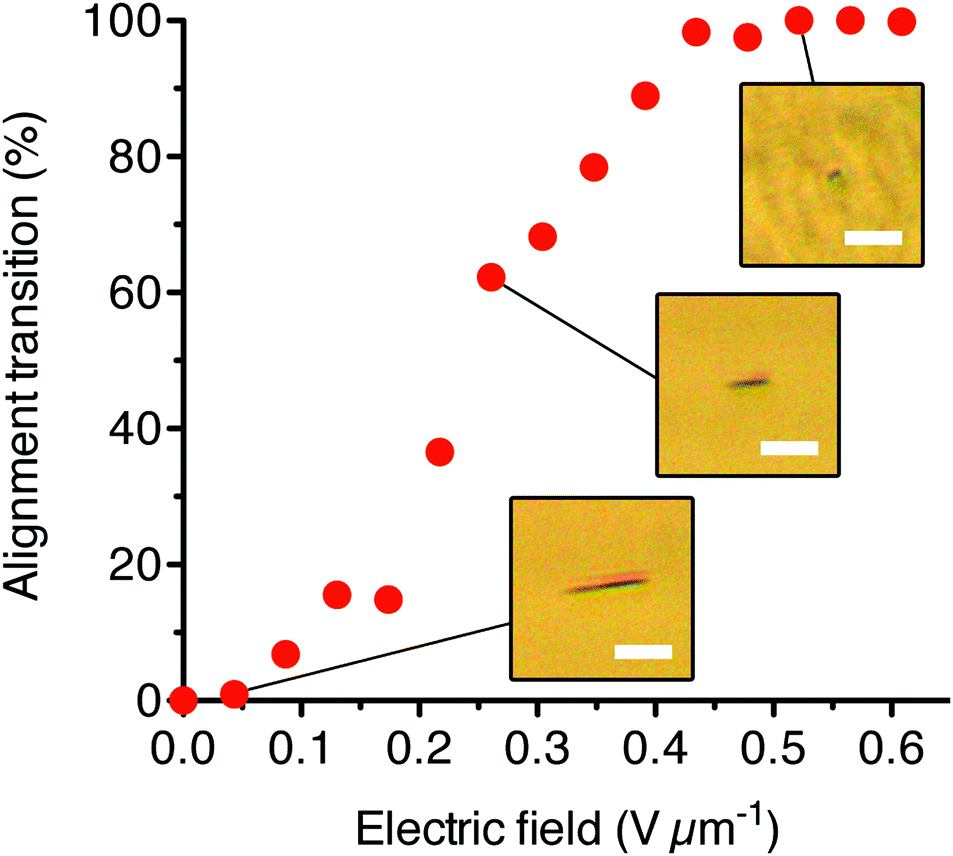 | ||
| Fig. 6 The degree of realignment of an in-plane aligned 14 μm AzoPIC bundle versus the applied homeotropic electric field (1 MHz). From 0.1 V μm−1, the bundle rotates homeotropically. At each electric field strength, the bundle was allowed to fully equilibrate to the field and the projected x–y length of the AzoPIC bundle was measured from the corresponding POM images and converted to the percentage of alignment transition. The scale bars indicate 10 μm. | ||
Conclusions
In this paper, we have demonstrated a generic approach to spatially and temporally control the organization of functional polymers, by using a combination of a liquid crystal template, a photopatternable substrate and electric fields. The stiff helical backbone of the polyisocyanide we employ are functionalized with strongly absorbing D–π–A-azobenzenes, which induces both tangential anchoring to the LCT and also introduces strong dichroic absorption characteristics when dispersed in 5CB. We find that the functionalized polymers are aligned within domains formed by the locally photopatterned liquid crystal template. When applying an electric field, the orientation of these polymers can be reversibly switched. The electric field strength is also directly related to the extent of the polymer rotation, which gives another level of dimensional control over these dispersed soft materials.Since in general, delicate molecular interactions between the LCT and the dispersed materials are absent, this hybrid approach can be applied to a wide range of other functionalized materials. Both the unique ability to dynamically switch the orientation of complex patterns of in-plane aligned materials and the adoption of photosensitive surfaces by the industry, should pave the way for the development and mass-manufacturing of soft matter based switchable optical and electric applications.
Acknowledgements
We would like to thank Merck for kindly providing 5CB and both Dr. Laura Cattaneo and Tonnie Toonen for their help with the photoalignment setup. We thank the TechnoCentrum for the fabrication of the cell construction apparatus and Onno van den Boomen for designing the 3D AzoPIC model. This work is supported (PvdA, PHJK) by NanoNextNL (grant 07A.07), a micro and nanotechnology consortium of the Government of the Netherlands and 130 partners.References
- L. Persano, A. Camposeo and D. Pisignano, Prog. Polym. Sci., 2015, 43, 48–95 CrossRef CAS.
- T. Kato, Y. Hirai, S. Nakaso and M. Moriyama, Chem. Soc. Rev., 2007, 36, 1857–2128 RSC.
- Y. Hirai, S. S. Babu, V. K. Praveen, T. Yasuda, A. Ajayaghosh and T. Kato, Adv. Mater., 2009, 21, 4029–4033 CrossRef CAS.
- N. S. Sariciftci, U. Lemmer, D. Vacar, A. J. Heeger and R. Janssen, Adv. Mater., 1996, 8, 651–654 CrossRef CAS.
- K. Akagi, G. Piao, S. Kaneko, K. Sakamaki, H. Shirakawa and M. Kyotani, Science, 1998, 282, 1683–1686 CrossRef CAS PubMed.
- S. W. Kang, S. H. Jin, L.-C. Chien and S. Sprunt, Adv. Funct. Mater., 2004, 14, 329–334 CrossRef CAS.
- O. Catanescu and L.-C. Chien, Adv. Mater., 2005, 17, 305–309 CrossRef CAS.
- S. Moynihan, P. Lovera, D. O'Carroll, D. Iacopino and G. Redmond, Adv. Mater., 2008, 20, 2497–2502 CrossRef CAS.
- X. Tong, D. Han, D. Fortin and Y. Zhao, Adv. Funct. Mater., 2012, 23, 204–208 CrossRef.
- M. D. Lynch and D. L. Patrick, Nano Lett., 2002, 2, 1197–1201 CrossRef CAS.
- W. Lee, C. Y. Wang and Y. C. Shih, Appl. Phys. Lett., 2004, 85, 513–515 CrossRef CAS.
- I. Dierking, G. Scalia, P. Morales and D. LeClere, Adv. Mater., 2004, 16, 865–869 CrossRef CAS.
- J. Lagerwall, G. Scalia, M. Haluska, U. Dettlaff-Weglikowska, S. Roth and F. Giesselmann, Adv. Mater., 2007, 19, 359–364 CrossRef CAS.
- N. Ould-Moussa, C. Blanc, C. Zamora-Ledezma, O. D. Lavrentovich, I. I. Smalyukh, M. F. Islam, A. G. Yodh, M. Maugey, P. Poulin, E. Anglaret and M. Nobili, Liq. Cryst., 2013, 40, 1628–1635 CrossRef CAS.
- P. C. Mushenheim, R. R. Trivedi, H. H. Tuson, D. B. Weibel and N. L. Abbott, Soft Matter, 2013, 10, 88 RSC.
- S. Zhou, A. Sokolov, O. D. Lavrentovich and I. S. Aranson, Proc. Natl. Acad. Sci. U. S. A., 2014, 111, 1265–1270 CrossRef CAS PubMed.
- P. C. Mushenheim, R. R. Trivedi, D. B. Weibel and N. L. Abbott, Biophys. J., 2014, 107, 255–265 CrossRef CAS PubMed.
- M. Hara, S. Nagano, N. Kawatsuki and T. Seki, J. Mater. Chem., 2008, 18, 3259–3263 RSC.
- P. van der Asdonk, H. C. Hendrikse, M. Fernandez-Castano Romera, D. Voerman, B. E. I. Ramakers, D. W. P. M Löwik, R. P. Sijbesma and P. H. J. Kouwer, Adv. Funct. Mater., 2016, 26, 2609–2616 CrossRef CAS.
- K. Miyachi, K. Kobayashi, Y. Yamada and S. Mizushima, SID Int. Symp. Dig. Tech. Pap., 2010, 41, 579–582 CrossRef.
- A. M. van Buul, E. Schwartz, P. Brocorens, M. Koepf, D. Beljonne, J. C. Maan, P. C. M. Christianen, P. H. J. Kouwer, R. J. M. Nolte, H. Engelkamp, K. Blank and A. E. Rowan, Chem. Sci., 2013, 4, 2357 RSC.
- A. B. Keereweer, P. H. J. Kouwer, E. Schwartz, S. Le Gac, R. J. M. Nolte and A. E. Rowan, Functional Supramolecular architectures for organic electronics and nanotechnology, 2010, ch. 5, pp. 135–154 Search PubMed.
- J. Cornelissen, J. Donners, R. de Gelder, W. S. Graswinckel, G. A. Metselaar, A. E. Rowan, N. Sommerdijk and R. J. M. Nolte, Science, 2001, 293, 676–680 CrossRef CAS PubMed.
- M. Kauranen, T. Verbiest, C. Boutton, M. N. Teerenstra, K. Clays, A. J. Schouten, R. J. M. Nolte and A. Persoons, Science, 1995, 270, 1–4 Search PubMed.
- J. Griffiths and K. C. Feng, J. Mater. Chem., 1999, 9, 2333–2338 RSC.
- N. Mizoshita, K. Hanabusa and T. Kato, Adv. Funct. Mater., 2003, 13, 313–317 CrossRef CAS.
- O. Yaroshchuk and Y. Reznikov, J. Mater. Chem., 2011, 22, 286–300 RSC.
- T. Seki, S. Nagano and M. Hara, Polymer, 2013, 54, 6053–6072 CrossRef CAS.
- E. Schwartz, S. Le Gac, J. J. L. M. Cornelissen, R. J. M. Nolte and A. E. Rowan, Chem. Soc. Rev., 2010, 39, 1576–1599 RSC.
- We did not measure the delay in response time of 5CB resulting from the presence of AzoPIC (or the corresponding monomer 5). The response time of our matrix is still orders of magnitude faster than that of the AzoPIC bundles.
- The presence of the defect line between the domains is attributed to the interfacial region between domains of strongly anchored in-plane aligned 5CB mesogens very close to the surface.
Footnote |
| † Electronic supplementary information (ESI) available. See DOI: 10.1039/c6tc02790c |
| This journal is © The Royal Society of Chemistry 2016 |