 Open Access Article
Improved charge carrier transport in ultrathin poly(3-hexylthiophene) films via solution aggregation†
Lukasz
Janasz
a,
Dorota
Chlebosz
b,
Marzena
Gradzka
b,
Wojciech
Zajaczkowski
c,
Tomasz
Marszalek
c,
Klaus
Müllen
c,
Jacek
Ulanski
*a,
Adam
Kiersnowski
*b and
Wojciech
Pisula
*ac
aDepartment of Molecular Physics, Lodz University of Technology, Zeromskiego 116, 90-924 Lodz, Poland. E-mail: jacek.ulanski@p.lodz.pl
bPolymer Engineering & Technology Division, Wroclaw University of Technology, Wybrzeze Wyspianskiego 27, 50-370 Wroclaw, Poland. E-mail: adam.kiersnowski@pwr.wroc.pl
cMax Planck Institute for Polymer Research, Ackermannweg 10, 55128 Mainz, Germany. E-mail: pisula@mpip-mainz.mpg.de
First published on 10th November 2016
Abstract
Field-effect transistors based on poly(3-hexylthiophene) (P3HT) bulk films exhibit maximum charge carrier mobilities of up to 0.1 cm2 V−1 s−1. However, reducing the thickness of the polymer film beyond 10 nm results in a significant deterioration of the charge transporting properties. In our work, we demonstrate a strategy towards ultrathin (i.e. thinner than 10 nm) polymer layers with charge carrier mobilities identical to bulk films. The improvement in conduction is related to aggregation of P3HT in solution allowing the formation of fibrils in the ultrathin films. Changing the molar mass of P3HT as well as varying the solvent type, aging time, and spin coating parameters resulted in layers with different thicknesses and fibrillar microstructures. The crystal packing and microstructure of the P3HT films, studied by atomic force microscopy and X-ray diffraction, were correlated with the transistor performance. It has been found that P3HT nanofibrils serve in the ultrathin films as pathways for charge carriers. Films of 8 nm thickness revealing a high density and a sufficient length of nanofibrils, along with pronounced internal crystallinity and long π-stacking coherence length, yield a mobility of 0.1 cm2 V−1 s−1. In this way, we demonstrated that controlling the microstructure of the active film in the ultrathin regime does not have to be at the expense of charge carrier mobility.
1 Introduction
Organic electronics has been undergoing a rapid development over the last few decades.1,2 Among its various potential applications the most recognized are large-area, flexible displays, solar cells and sensors.3–6 Nowadays, organic semiconducting materials exhibit device performances comparable to amorphous silicon.7 Further development in both designing new semiconductors and optimization of devices is vital to meet the requirements for commercialization.8 Conjugated polymers, such as regioregular poly(3-alkylthiophenes) (P3ATs), play an important role as semiconductors in organic electronics due to their charge transporting properties and ability to form thin films.9 The ease of low-temperature, solution-based processability makes polymers promising candidates for large scale processing, like roll-to-roll large-area printing.10,11 The charge carrier transport in the films depends on the intramolecular conjugation of the π-orbitals along the polymer backbone and intermolecular π-interactions of neighboring chains.12 Controlling the microstructure and crystallinity of the films is of great importance in order to achieve efficient charge transport.12 Also the microstructure of the crystalline domains determines the density of percolation paths for the charge carriers.Poly(3-hexylthiophene) (P3HT), an important member of the P3AT family, is widely used in organic electronics due to its efficient hole-transporting properties and good solubility in a variety of organic solvents.13 The crystalline structure and microstructure of P3HT films can be tuned by controlling the crystallization conditions,14e.g. by depositing the films from solvents having different thermodynamic affinities to the polymer, which can be expressed by the difference in the Hansen solubility parameters.15 All those parameters are known to influence the microstructure and therefore also have an effect on the electronic parameters of the devices like organic field-effect transistors (OFETs) and organic photovoltaic cells (OPVs). Different techniques to induce aggregation of P3HT in solution have been investigated.16–20
It is believed that aggregation of P3HT in solution caused by specific interactions between macromolecules directly precedes the formation of solid crystals. Hence, controlling the solution aggregation of P3HT can be considered as a strategy to enhance ordering of the polymer in the solid state, i.e. in the films. It is also known that controlled aggregation of P3HT in solution enhances the formation of fibrillar structures. These fibrillar microstructures were widely reported as beneficial for the properties of P3HT-based OFET devices, since elongated nanofibrils provide transporting paths between the source and the drain electrodes of a transistor and increase the mobility over one order of magnitude in comparison to OFETs with disordered P3HT films.16,20–23 The aggregation can be for instance favored by solvent assisted drop casting yielding 50–100 nm thick films.24
Here we present a systematic study on the relationships between solution crystallization and crystal structure as well as microstructure of P3HT at the interface. The structural properties of P3HT films were further correlated with charge carrier mobility in OFET devices. In our work, we paid special attention to the aggregation of the polymer in solution as a method to control both the crystallinity and microstructure of P3HT ultrathin films directly at the transistor dielectric. It is known that the charge transport in the OFET channel occurs mainly at the interface between the active layer and the dielectric surface.25 Therefore, studies on ultrathin films with thicknesses below <10 nm, as presented here, allowed the examination of the charge transporting layers to correlate realistically the structural features of the film with the charge carrier mobility. Moreover, the precise thickness control allowed monitoring the building-up of the conductive layer and gaining insight into the impact of the microstructure on the charge transport in transistors at different stages of the film growth. Ultrathin semiconductive films with sufficiently high charge carrier mobility also have potential for practical applications in transparent and highly flexible devices.26 In this work, we demonstrate that precise control of the crystallization conditions results in ultrathin P3HT films with hole mobilities as high as 0.1 cm2 V−1 s−1, i.e. being in the same range as in bulk films. The right type of solvent, high molecular weight of P3HT along with other factors such as surface treatment and solution aging time allow the fabrication of ultrathin, efficient and reproducible OFETs. This approach towards improvement of charge carrier transport in ultrathin films may also be applicable for a wider range of conjugated polymers.
2 Experimental section
2.1 Materials
P3HT polymers were purchased from Ossila and used as received. Two polymers were applied for the performed experiments: (1) P3HT with Mw = 94.1 kg mol−1 (polydispersity index, PDI = 1.90) and regioregularity (RR) = 95.5% and (2) P3HT with Mw = 34 kg mol−1 (PDI = 1.75) RR = 94.7%. In the paper these polymers are referred to as P3HT94 and P3HT34, respectively. Chloroform and toluene (both HPLC grade) were purchased from Sigma-Aldrich and used as received.2.2 Preparation and measurements of OFETs
In order to investigate the aggregation of P3HT in solution and the influence of aggregation on the formation of P3HT crystalline structures, the solutions of P3HT in chloroform or toluene were prepared. 2 mg of P3HT were dissolved in 1 mL of either solvent under a nitrogen atmosphere in a glove-box and stirred for 5 h at 50 °C. In order to age the solutions and induce polymer aggregation, the solutions were stored in the glove-box at ∼20 °C over a defined period of time. The semiconducting properties of the P3HT films were investigated in organic field-effect transistors in the bottom gate, top contact configuration. Silicone substrates with a 300 nm silicone dioxide layer were applied as substrates. The substrates were washed in acetone and isopropanol in an ultrasonic bath for 15 min. Subsequently, they were treated with oxygen plasma for 5 min and annealed at 140 °C in HMDS vapor for 6 h. The layers were deposited by spin-coating. In the case of fresh solutions, films were deposited from solutions heated to 50 °C, while the temperature of the aggregated solutions was 20 °C. The P3HT films were annealed at 70 °C for 1 h. The gold source and drain electrodes, 50 nm in thickness, were thermally evaporated through a shadow mask. On one substrate 20 OFETs with 30 μm long and 1 mm width channels were produced. OFET measurements were performed by using a Keithley 2634B source meter. Transfer and output characteristics were measured in the range from 10 V to −80 V under a nitrogen atmosphere. The charge carrier mobility was derived from transfer characteristics in the saturation regime. For each sample ten transistors were measured and average values are presented in the paper. Output and transfer characteristics, along with working parameters, are presented in the ESI† (Fig. S3–S5 and Tables S2–S7).2.3 UV-VIS absorption spectroscopy
The UV-VIS absorption spectra were recorded at 20 °C on the Perkin Elmer Lambda 900 UV-Visible-near-IR spectrophotometer. In order to study the aggregation of P3HT the stock solutions (0.2 mg mL−1) in chloroform or toluene were stored in closed vials at 20 °C in the dark for 1, 4 or 6 months. Directly prior the measurements, the solutions were diluted approx. 10 times and immediately measured in 10 mm quartz cuvettes. Data were normalized according to the concentration determined from the calibration plots.2.4 X-ray diffraction measurements
The specimens for X-ray diffraction measurements were prepared by crystallization of P3HT on the clean 20 × 20 mm aluminum substrates from 2 mg mL−1 solutions. The measurements were performed using a pseudo-GIWAXS geometry, a 1.2 kW (50%) copper source (CuKα, λ = 0.1542 nm), cross-coupled Göbel mirrors and a pinhole collimation system. The data were recorded on the MAR345 image plate detector during 6 h exposure time. The camera length (342 mm), and hence the detector q-range (1.85 Å−1) was roughly calibrated using a silver behenate standard. After the conversion of two-dimensional to one-dimensional diffraction patterns, the peak positions were refined based on a comparison with 200 peak profiles measured for the same samples using a fixed-camera length (285 mm) Ultima IV diffractometer fitted with a 2 kW X-ray tube (CuKα, monochromatized with a curved graphite monochromator). The Ultima IV diffractometer was calibrated using both silver behenate and corundum standards. The data were subjected to normalization, and background correction using an OriginPro 8.6 computer program. The profiles were deconvoluted using multiple (7×) Lorentzian profiles and monoclinic unit cell parameters.27 The fitting algorithm was optimized to hold assumed peak positions and maximize the area of the amorphous halo. The first P3HT peak (100) was excluded from the pattern fitting because of its large area, which lowered the accuracy of the fit in the fingerprint region (0.7–1.85 Å−1). The relative XRD crystallinity indices were determined from the deconvoluted regions of the XRD patterns according to the methods extensively described in the literature.28–30 The screening of the samples and determination of the measurement methodology were performed at the BL9 beamline at DELTA synchrotron facility in Dortmund (Germany).2.5 Differential scanning calorimetry
DSC experiments were done using the Mettler Toledo DSC1 system, coupled to a Huber TC 100 intracooler. The instrument was calibrated using indium standard (Tm = 156.6 °C. ΔHm = 28.45 J g−1). Samples of P3HT (∼2 mg) were deposited in the form of films in 40 μL aluminum crucibles and heated/cooled under a constant nitrogen purge according to the following protocol: heating: −60 °C to 260 °C; thermal equilibration at 260 °C for 2 min; cooling from 260 °C to −60 °C. The heating/cooling ramps were set to 10 °C min−1. The mass crystallinity indices and melting points were extracted from the first scan obtained for the as-casted samples using, after the literature, the standard heat of fusion ΔH0 = 37 J g−1.29 The experimental data were processed using the generic STARe computer program.2.6 AFM measurements
A Veeco Dimension 3100 Atomic Force Microscope was used to investigate the microstructure and to determine the thickness of the polymer films. All images were obtained in the tapping mode using Olympus silicone cantilevers with a 320 kHz resonance frequency. The film thickness was determined using the NanoScope Analysis software by plotting the step – high diagrams that represent the average cross sections.3 Results and discussion
It is known that crystallinity and microstructure exert an influence on the hole mobility in P3HT-based OFETs.31 In other words, gaining control over crystallinity and microstructure of P3HT films can be considered a tool to tailor the electronic properties of OFETs. Among various methods to control the formation of P3HT crystals, aggregation of the polymer in solution, which precedes crystallization during film formation, seems particularly important. This is because aggregation of P3HT macromolecules may occur spontaneously upon solution aging and actually it is inevitable in solution-processing of P3HT.32 The aggregation and solution crystallization depend on a number of parameters of which the polymer–solvent interactions as well as molar mass of the polymer seem the most important being easy to control at the same time.17 Solution aging is a known strategy to obtain P3HT fibrils which can be deposited on the substrate using a variety of methods.15 However, until now, the impact of such structures on ultrathin films has not been systematically investigated.The motivation of this study was to correlate the crystal structure, microstructure and electronic properties to enable a better understanding for the dominating processing parameters of ultrathin film transistors. Hence, in our study we determined the influence of the experimental variables, namely molar mass, solvent and aggregation induced by aging upon crystallization and formation of ultrathin P3HT films. We started from seeking for general trends in the aggregation and crystallization of P3HT with low (34 kg mol−1, abbreviated as P3HT34) or high (94 kg mol−1, P3HT94) molar masses from either chloroform or toluene solutions. We note here that the formation of aggregates is believed to occur mainly in solution, from which they are transferred to the substrate surface. This is also why our approach based on a relatively direct comparison between the crystallinity and the crystal structure of bulk and the ultrathin films can be considered justified. That is because both reveal a fibrillar microstructure when crystallized from solution. In the following sections we discuss the effects related to the crystallization and formation of the ultrathin films of P3HT from chloroform or toluene.
3.1 The influence of molar mass, solvent, and aggregation on the crystal structure and crystallinity of poly(3-hexylthiophene)
In our approach, we compared the crystallization from chloroform and toluene as these two solvents are among the most commonly used in solution processing of P3HT.13,17,33 Further, the solubility parameters of the solvents and the polymer (Table S1, ESI†) indicated that toluene and chloroform have different thermodynamic affinities to P3HT, which pointed towards different aggregation and crystallization behaviors and additionally justified our selection.34 The aggregation of P3HT was manifested by turning the solution from orange to dark red.15 For 2 mg mL−1 P3HT solutions used for the fabrication of the OFET devices the time after which a distinct color change occurred depended on the solvent type. The toluene solutions turned red after several hours, while a distinct color change in chloroform required several days. The observed color changes related to solution aggregation were additionally confirmed by UV-VIS spectroscopy. As expected, aging the dilute (∼0.01 mg mL−1) solutions gave rise to additional bands in the UV-VIS spectra at around 563 and 610 nm, which is characteristic of P3HT aggregation (Fig. 1).23 The notable change in the spectral properties was observed earlier for toluene than for chloroform indicating that aggregation of P3HT in toluene is faster than in chloroform. The absorption spectra also indicate the presence of a non-aggregated polymer fraction in the aged solutions. Therefore, the resulting films cast from aged solutions contain both aggregated and non-aggregated polymer chains. To gain information on the crystal structure of P3HT crystallized from different solvents the XRD analysis of P3HT34 and P3HT94 specimens was performed for films obtained from either fresh or aged for 1 month solutions in chloroform and toluene. XRD patterns with distinct, well-resolved diffraction peaks and sufficient intensity were acquired by performing the analysis for films with a thickness in the range of 200–500 nm. Performing such analysis for thin films of several to several-tens nanometers was not possible because of the insufficient scattered intensity. OFETs based on P3HT films with thickness in this range exhibit a similar performance to the ultrathin films (Table S2, ESI†). In order to enable a quantitative analysis of crystal sizes the acquired 2D patterns were converted into one-dimensional I(q) XRD plots. The XRD patterns (Fig. S1 and S2, ESI†) suggest that irrespective of the type of solvent or aging P3HT forms similar crystal structures. The fingerprint regions of the XRD patterns of P3HT were satisfactorily resolved using a monoclinic unit cell with parameters of a = 15.6 ± 0.25 Å, b = 7.57 ± 0.03, c = 0.7–0.9 Å and γ = 87° in the way reported earlier.27 The c axis could not be unambiguously resolved (hence the range) because of the limited number of the unique, resolved diffraction peaks. The deconvolution of the XRD patterns allowed us to determine the relative (Scherrer) sizes of crystalline domains and also relative crystallinity indices ( ) of the polymer, which enabled further analysis of the influence of solution aging on the structural properties of the solid P3HT. In order to verify the
  values, we have additionally determined the DSC crystallinity (XDSCc) for the films as mentioned above. The Xc values are given in Tables 1 and 2 for P3HT34 and P3HT94. P3HT crystals are formed as a result of π-stacking of neighboring P3HT chains and interactions of the alkyl chains between subsequent layers formed by π–π stacked thiophene sheets. The dimensions of crystals (or more precisely coherence of the crystalline structure) in the ‘π-stacking’ or ‘alkyl-stacking’ directions can be considered proportional to the 0k0 and h00 directions in the reciprocal space. Hence, in this approach Scherrer crystal sizes calculated from 020 and 200 diffraction profiles are compared. These dimensions are abbreviated as t020 and t200. The results of the analysis are shown in Tables 1 and 2. The analysis of the data in Tables 1 and 2 indicates that aging as well as solvent and molar mass exerts a noticeable influence on the crystallization of P3HT. In the case of P3HT34, crystallization from either fresh or aged chloroform results in the formation of crystalline domains with similar alkyl- and π-stacking coherence lengths. Aggregation in chloroform causes only an indistinct increase in t020 of the P3HT34 crystals. The
  values are similar irrespective of whether P3HT34 was crystallized from fresh or aged chloroform solution. A small difference in trends between
  and XDSCc may suggest that apart from fully developed crystals there is a number of small ordered domains whose sizes are insufficient to contribute to coherent diffraction effects. Aggregation of P3HT34 in toluene apparently causes a preferential growth of polymer crystals in the [0k0] (π-stacking) direction and a decrease in crystal thickness along the [h00] vector. At the same time, a small drop in the overall crystallinity of the polymer crystallized from aged solution in comparison to that crystallized from fresh solution is observed (Table 1).
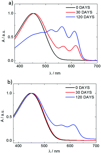 | ||
| Fig. 1 UV-VIS spectra of P3HT94 solutions in toluene (a) and chloroform (b) aged for periods of time given in the insets. | ||
In the case of P3HT94, solution aging causes a distinct increase in the π-stacking coherence length, irrespective of the solvent. Aggregation in solution causes also an increase in t200 which, interestingly, is more distinct in the case of P3HT94 crystallized from toluene where a drop in t200 was observed for P3HT34. Another interesting observation is that the aging in chloroform and toluene exerts different effects on crystallinity. As revealed by XRD measurements and verified by DSC, the aggregation of P3HT94 in chloroform causes a minor increase in crystallinity, while in the case of toluene, the overall crystallinity drops by over 15% similar to that observed for P3HT34. The results indicate that aggregation of P3HT in chloroform generally promotes the formation of the crystalline phase. A comparison of the results for aging (Tables 1 and 2) suggests that in the case of toluene the aggregation of P3HT improves inherent crystal perfection at the expense of the overall crystallinity. In other words, it seems that aging in toluene causes the formation of less, but better developed crystals with sizes indistinctly smaller in comparison to crystals formed from chloroform.
To conclude this section, it can be generally said that solution aging enhances π-stacking irrespective of the solvent used. The influence of aging on the polymer crystallinity depends on solvent and molar mass, but solution aging effects are more clear for the polymer with a higher molar mass, i.e. P3HT94. Furthermore, the P3HT94 crystalline domains formed from aged toluene are slightly smaller than those from aged chloroform.
3.2 Effects of solution aging on the microstructure and charge carrier mobility of ultrathin P3HT films
As mentioned in the preceding section, aggregation of P3HT in chloroform and toluene requires different time periods. Aggregation of P3HT in toluene occurs within hours, while in chloroform it occurs within days. For equilibration the chloroform and toluene solutions were stored in closed vials at 20 °C for 1 month before spin-coating the film. A film thickness of ca. 8.0 nm was obtained as derived from profile measurements presented in Fig. 2. A full set of step-high measurements for different films is shown in the ESI† (Fig. S6–S9). The effects of one-month aging of both solutions on the microstructure of the P3HT94 films are shown in the Fig. 3. To illustrate the relationship between the microstructure and charge transport properties, the OFET transfer characteristics are presented in Fig. 4. The films obtained from both aged solutions exhibited a characteristic fibrillar microstructure (Fig. 3b and d) with an average fibril length of the order of microns and a thickness of approx. 30 nm. Further details on the fibril dimensions are given in the ESI† (Fig. S10 and Table S8). In the case of films obtained from chloroform (Fig. 3b) the fibrils were significantly denser and closely packed, while fibrils from toluene (Fig. 3d) were less compact and were further separated from each other. In contrast, fibrillar structures were not formed in the films obtained from the fresh chloroform solution (Fig. 3a). In the case of the film deposited from fresh toluene solution only short (0.5 μm) and loose fibrillar aggregates could be noticed (Fig. 3c). This suggested that aggregation in toluene started immediately after removing the solution from the hot-plate in order to deposit the film. To investigate the influence of the microstructure on the charge carrier transport, the OFET performance was determined and is summarized in Table 3. The average mobility for the films obtained from chloroform increased by one order of magnitude from 3.7 ± 0.1 × 10⁻³ cm2 V−1 s−1 for the fresh solution to 5.8 ± 0.3 × 10⁻² cm2 V−1 s−1 for the aged solution. In the case of toluene, the mobility improvement was weaker but still well pronounced from 5.1 ± 0.4 × 10⁻³ cm2 V−1 s−1 to 1.1 ± 0.1 × 10⁻² cm2 V−1 s−1 for the pristine and aged solution, respectively. It has been reported that the P3HT fibrils contain polymer chains folded in a way which promotes backbone alignment perpendicular to the fibril.18 This means that charge carriers along the fibril are transported via π-stacking. On the other hand, higher mobilities are achieved when charge conduction takes place perpendicular to the fibril assemblies because the transport occurs along the conjugated backbones, which also partly bridge the closely packed fibrils.35,36 The transport between neighboring fibrils is also highly sensitive to the distance between the elongated assemblies.37 Taking these reports into account, the higher mobility for films cast from aged chloroform solutions in comparison to aged toluene is related to the transport along the P3HT chains and perpendicular to neighboring fibrils. These observations indicate the importance of fibril entanglement in films thinner than 10 nm, where the charge carrier transport is severely sensitive to the quality of the semiconductor/dielectric interface. Similar mobilities recorded for P3HT94 films cast from fresh solutions for both solvents could be explained in terms of identical crystal structures, crystallinity indices and π-stacking coherence lengths of P3HT94 irrespective of the solvent used (Table 2). This suggests that in the case of relatively uniform films formed from fresh and non-aggregated P3HT solutions (Fig. 3a and c) the charge carrier mobility may rather depend on crystallinity and unit cell parameters than on minor changes in the microstructure.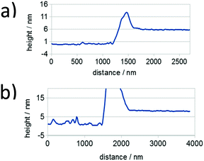 | ||
| Fig. 2 Representative thickness profiles for P3HT94 films deposited from (a) toluene and (b) chloroform solutions. Height peaks are a result of the mechanical removal of the film. | ||
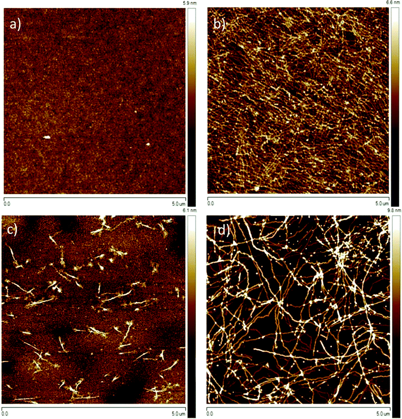 | ||
| Fig. 3 Tapping mode AFM height images of P3HT films deposited from (a) fresh and (b) 1 month aged chloroform; (c) fresh and (d) 1 month aged toluene solutions. | ||
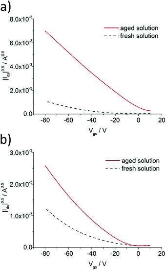 | ||
| Fig. 4 Transfer characteristics of P3HT94 based OFETs deposited from (a) fresh and 1 month aged chloroform and (b) fresh and 1 month aged toluene solutions. | ||
| Chloroform | Toluene | |||
|---|---|---|---|---|
| Fresh | Aged | Fresh | Aged | |
| μ/cm−2 V−1 s−1 | 3.7 ± 0.1 × 10⁻³ | 5.8 ± 0.3 × 10⁻² | 5.1 ± 0.4 × 10⁻³ | 1.1 ± 0.1 × 10⁻² |
3.3 Influence of aging time on charge carrier mobility of ultrathin P3HT films
To investigate the influence of aging time on the charge transport properties, the solutions of P3HT94 in chloroform and toluene at the same concentration of 2 mg mL−1 were aged for different time periods and subsequently spin-coated and used as active OFET layers with an average thickness of ∼8 nm. Fig. 5 shows hole mobility as a function of aging time. In the case of chloroform (Fig. 5a), the hole mobility remained unchanged for 24 hours of aging, while it increased over one order of magnitude after one week. The highest measured mobility of around ∼0.1 cm2 V−1 s−1 was obtained after aging of P3HT94 in chloroform for over 4 months. In the case of toluene (Fig. 5b), the mobility increase induced by polymer aggregation occurred significantly already during the first 5 hours of aging. The maximum measured value of around 1.7 × 10⁻² cm2 V−1 s−1 for toluene was obtained after 4 months of aging. Therefore, it can be postulated that after a certain saturated aggregation state of P3HT94 is achieved after several days in chloroform and several hours in toluene, the electrical parameters of the films remain unaffected. Moreover, the non-aggregated polymer fraction seems to have only a minor impact on the charge carrier mobility. In the case of toluene, the non-aggregated fraction decreased over time between solutions aged for 30 and 120 days (Fig. 1a), while only a slight increase of mobility was observed. In the case of chloroform, the non-aggregated fraction remained at the same level over the whole investigated time period (Fig. 1b).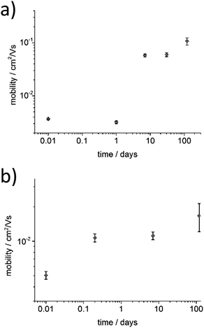 | ||
| Fig. 5 Dependence of the hole mobility and aging time for (a) chloroform and (b) toluene P3HT94 solutions. | ||
Interestingly, differences in hole mobilities observed for spin-coated films from P3HT94 solutions after 10-days or 4-month aging were not related to differences in film microstructures. These differences in mobility can, however, be rationalized by taking into account the crystallinity parameters listed in Table 2. It is clear that, in comparison to toluene, aggregation of P3HT94 in chloroform promoted crystallinity and formation of larger crystalline domains. Let us note that higher crystallinity is not only translated to higher density of fibrils in the film but also to a higher inherent ordering in the fibrils, while both the number of fibrils and their ordering can exert an influence on mobility figures.20 Since we observed neither an increase in the fibril lengths nor in the fibril density resulting from 4-month aging of the solutions, we can hypothesize that the long-term aging enhanced ordering (crystallinity) of P3HT in the fibrils and hence improved the charge carrier mobility. The different effects of chloroform and toluene on the crystallization of P3HT together with the unchanged film microstructures would explain why, irrespective of the absolute numbers, the hole mobility ratios after 10-days or 4-months of ageing were still different by a factor of approx. 5.5.
3.4 Dependence of charge carrier mobility on P3HT layer thickness and microstructure
Varying the spin-coating speed, necessary to obtain ultrathin films from aged P3HT solutions, allowed a precise control over the thickness to investigate the microstructure upon film growth. P3HT94 aged in toluene for 1 month at the concentration of 2 mg mL−1 was used for this series and the resulting films were studied by AFM and as active films in OFETs (Fig. 6 and 7). The thinnest layers consisted of single nanofibrils mostly separated from each other, which were randomly distributed on the SiO2 substrate. The nanofibril height was around 2.5 nm (Fig. S10, ESI†). This monolayer microstructure corresponded to a quasi-two-dimensional network of percolation paths. Interestingly, this network permitted a transport of charges with a mobility of 6.5 × 10⁻³ cm2 V−1 s−1 which was even slightly higher in comparison to thicker films of 8 nm obtained from pristine toluene yielding a uniform film microstructure. Upon increasing the film thickness the nanofibril network became denser providing more percolation paths for the charge carriers. The charge carrier mobility increased for thicker films up to 2 × 10⁻² cm2 V−1 s−1 indicating a transition from a quasi-two-dimensional network to a more complex 3D nanofibril structure. Furthermore, as mentioned in Section 3.2, a denser fibril network favors charge transport along the polymer backbones and therefore is perpendicular to the long fiber axis. The pronounced improvement in mobility by 100% is impressive for a relatively small increase in the thickness of around 5 nm.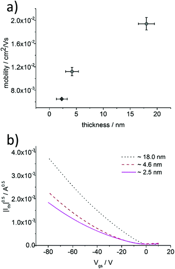 | ||
| Fig. 6 (a) Dependence between charge carrier mobility and P3HT94 film thickness deposited from aged toluene solution, (b) transfer characteristics of P3HT94 films of different thicknesses. | ||
 | ||
| Fig. 7 Tapping mode AFM height images of P3HT94 films deposited from aged toluene solutions with different thicknesses of around (a) 2.5 nm, (b) 4.6 nm and (c) 18.0 nm. | ||
3.5 Influence of molar mass on P3HT film microstructure and charge carrier transport
An influence of molar mass was another point to explain in course of our studies. As indicated in Tables 1 and 2 in Section 3.1, an increase of the molar mass of P3HT from 34 to 94 kg mol−1 caused considerable changes in crystallinity and crystal sizes. The changes caused by the molar mass depended, however, on the type of solvent. In the case of 1 month aged chloroform solutions, an indistinct decrease in crystallinity and a notable increase in the π-stacking coherence length (t020) were observed for the higher molar mass (Table 2). For P3HT crystallized from the 1 month aged toluene solution, we observed that the increase in the molar mass caused an increase in t020 by 10% and a proportional, also approx. 10% increase in crystallinity. Let us note that aging of P3HT34 in toluene caused an ∼69% increase in t020 while aging of P3HT94 resulted in an increase of t020 by approx. 26%. At the same time, we observed that crystallization from the 1 month aged toluene solution caused a drop in P3HT crystallinity by 15–20% irrespective of the molar mass. Such changes in t020 suggest that aging of P3HT in toluene solutions favors the formation of fewer but larger (or better ordered, considering the nature of the Scherrer estimation used to determine thkl) crystalline domains, which is particularly pronounced for P3HT34. On the other hand, however, the largest crystalline domains and the highest crystallinity figures were observed for P3HT94, which may suggest that aging of P3HT with the higher molar mass in toluene should be beneficial for the OFET performance.Films of P3HT94 and P3HT34 obtained from 1 month aged toluene solutions were measured with AFM, in order to investigate their microstructure. The analysis indicated that the fibrils of P3HT34 were on average 1 μm long (Fig. 8), while the length of P3HT94 fibrils was several microns. We determined hole a mobility of 2.3 ± 0.2 × 10⁻³ cm2 V−1 s−1 and 1.00 ± 0.1 × 10⁻² cm2 V−1 s−1 for P3HT34 and P3HT94, respectively (transfer characteristics presented in Fig. 9). The differences in fibril lengths together with the above-mentioned differences in crystallinity and crystal coherence lengths of P3HT34 and P3HT94 may explain the observed differences in the hole mobility. The fibril width of ca. 30 nm for P3HT94 is larger than of ca. 46 nm for P3HT34. It has been reported that the fibril width of P3HT significantly improves the charge transport.38 Despite the fact that P3HT34 fibrils are wider, the corresponding charge carrier mobility is still lower than in the case of P3HT94. The poorer performance is attributed to severely separated P3HT34 fibrils which are obtained by aging and subsequent spin-coating at an extremely high rotating velocity. Furthermore, the mobility of 2.5 ± 0.3 × cm2 V−1 s−1 is identical for films obtained from fresh and old toluene solutions indicating that, in the case of P3HT34, the fibrillar film structure has no impact on the charge transport due to an insufficient length of the fibrils. Considering the magnitude of changes in hole mobility caused by the formation of a fibrillar microstructure (cf. Section 3.2) the improved OFET performance for P3HT with higher molar mass can be mainly related to the formation of longer, densely interconnected fibrils providing longer conducting paths in the P3HT films. Despite the strong aggregation of P3HT34 the charge carrier transport is not improved. This observation again underlines the importance of fibril entanglement in the ultrathin films. In spin-coated ultrathin films, a sufficient entanglement of fibrils is difficult to achieve due to limitations of the thickness itself and special separation of the assemblies, which occurs because of high centrifugal forces acting during the film formation. It is important to emphasize that aggregation itself does not necessarily improve the charge carrier transport when it is not accompanied by an appropriate microstructure. Less aggregated, but more entangled assemblies may provide better conduction paths for the charge carriers and result in higher mobilities, as shown in the comparison of films obtained from P3HT94 and P3HT34.
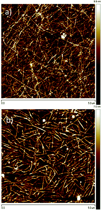 | ||
| Fig. 8 Tapping mode AFM height images of films deposited from 1 week aged toluene solutions for P3HT with (a) Mw = 94 kDa and (b) Mw = 34 kDa. | ||
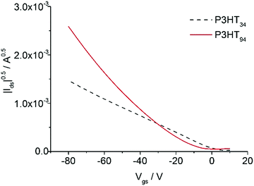 | ||
| Fig. 9 Transfer characteristics of P3HT34 and P3HT94 films obtained from 1 month aged toluene solutions. | ||
The increase of mobility with higher P3HT molar mass has already been reported for both pristine and aggregated solutions.17,18 In comparison to this, we present a straightforward way to control the length of nanofibril aggregates in ultrathin active films by changing the molar mass of P3HT. Moreover, studies on ultrathin films allow us to establish a direct relation between fibril length and charge carrier mobility, having in mind, that charge transport occurs in the first few monolayers at the semiconductor/dielectric interface.
4 Conclusions
The type of solvent, molar mass of the polymer, time of aging and film thickness are factors which influence significantly the microstructure and electrical parameters of ultrathin P3HT films. P3HT nanofibrils that are created in solution during aging provide conducting paths, and the charge-carrier mobility strongly depends on their density and length. The charge carrier mobility as high as 0.1 cm2 V−1 s−1 was achieved for transistors with ∼8 nm thick active films consisting of densely packed and long nanofibrils deposited from aged chloroform solution. Such mobility is at the same level as previously reported for bulk P3HT films.2 These results indicate that by adjusting the microstructure of ultrathin polymer films the charge transport is maximized to the level of bulk films and a high device performance is achieved. In the case of P3HT, the microstructure is improved due to increased aggregation induced by aging. The question is if this concept is also applicable to other conjugated polymers to achieve bulk transport properties already in ultrathin films which are attractive for transparent and/or flexible electronics.Acknowledgements
This work was supported by National Science Centre, Poland through the grant DEC-2013/08/M/ST5/00914 and by Foundation for Polish Science through the grant MASTER/MISTRZ 9/2013. We gratefully acknowledge the DELTA electron storage ring in Dortmund (Germany) for a beamtime enabling preliminary X-ray diffraction measurements.Notes and references
- C. Wang, H. Dong, W. Hu, Y. Liu and D. Zhu, Chem. Rev., 2012, 112, 2208–2267 CrossRef CAS PubMed.
- S. Holliday, J. Donaghey and I. McCulloch, Chem. Mater., 2014, 26, 647–663 CrossRef CAS.
- Y. Yang, G. Zhang, H. Luo, J. Yao, Z. Liu and D. Zhang, ACS Appl. Mater. Interfaces, 2016, 8, 3635–3643 CAS.
- H. Zhou, L. Yang and W. You, Macromolecules, 2012, 45, 607–632 CrossRef CAS.
- T. Someya, T. Sekitani, S. Iba, Y. Kato, H. Kawaguchi and T. Sakurai, Proc. Natl. Acad. Sci. U. S. A., 2004, 101, 9966–9970 CrossRef CAS PubMed.
- T. Sekitani, H. Nakajima, H. Maeda, T. Fukushima, T. Aida, K. Hata and T. Someya, Nat. Mater., 2009, 8, 494–499 CrossRef CAS PubMed.
- J. Mei, Y. Diao, A. Appleton, L. Fang and Z. Bao, J. Am. Chem. Soc., 2013, 135, 6724–6746 CrossRef CAS PubMed.
- C. Sekine, Y. Tsubata, T. Yamada, M. Kitano and S. Doi, Sci. Technol. Adv. Mater., 2014, 15, 034203 CrossRef PubMed.
- A. Facchetti, Chem. Mater., 2011, 23, 733–758 CrossRef CAS.
- R. Sondergaard, M. Hösel and F. Krebs, J. Polym. Sci., Part B: Polym. Phys., 2013, 51, 13–34 Search PubMed.
- H. Yan, Z. Chen, Y. Zheng, C. Newman, J. Quinn, F. Dötz, M. Kastler and A. Facchetti, Nature, 2009, 457, 679–686 CrossRef CAS PubMed.
- H. Tsao and K. Müllen, Chem. Soc. Rev., 2010, 39, 2371–2386 RSC.
- J. Chang, B. Sun, D. Breiby, M. Nielsen, T. Sölling, M. Giles, I. McCulloch and H. Sirringhaus, Chem. Mater., 2004, 16, 4772–4776 CrossRef CAS.
- M. McGehee and R. Kline, J. Macromol. Sci., Polym. Rev., 2006, 46, 27–45 CrossRef.
- U. Bielecka, P. Lutsyk, K. Janus, J. Sworakowski and W. Bartkowiak, Org. Electron., 2011, 12, 1768–1776 CrossRef CAS.
- M. Chang, D. Choi, B. Fu and E. Reichmanis, ACS Nano, 2013, 7, 5402–5413 CrossRef CAS PubMed.
- H. Hu, K. Zhao, N. Fernandes, P. Boufflet, J. Bannock, L. Yu, J. de Mello, N. Stingelin, M. Heeney, E. Giannelis and A. Amassian, J. Mater. Chem. C, 2015, 3, 7394–7404 RSC.
- M. Chang, J. Lee, P. Chu, D. Choi, B. Park and E. Reichmanis, ACS Appl. Mater. Interfaces, 2014, 6, 21541–21549 CAS.
- A. Aiyar, J. Hong, J. Izumi, D. Choi, N. Kleinhenz and E. Reichmanis, ACS Appl. Mater. Interfaces, 2013, 5, 2368–2377 CAS.
- U. Bielecka, K. Janus and W. Bartkowiak, Proc. SPIE, 2014, 9185, 91850E CrossRef.
- S. Tiwari, W. Takashima, S. Balasubramanian, S. Miyajima, S. Nagamatsu, S. Pandey and R. Prakash, Jpn. J. Appl. Phys., 2014, 53, 021601 CrossRef.
- M. Chang, J. Lee, N. Kleinhenz, B. Fu and E. Reichmanis, Adv. Funct. Mater., 2014, 24, 4457–4465 CrossRef CAS.
- N. Kleinhenz, C. Chatterjee, M. Chang, K. Nayani and Z. Xue, Chem. Mater., 2015, 27, 2687–2694 CrossRef CAS.
- K. Singh, T. Young, R. McCullough, T. Kowalewski and L. Porter, Adv. Funct. Mater., 2010, 20, 2216–2221 CrossRef CAS.
- S. Wang, A. Kiersnowski, W. Pisula and K. Müllen, J. Am. Chem. Soc., 2012, 134, 4015–4018 CrossRef CAS PubMed.
- D. Khim, G. Ryu, W. Park, H. Kim, M. Lee and Y. Noh, Adv. Mater., 2016, 28, 2752–2759 CrossRef CAS PubMed.
- D. Dudenko, A. Kiersnowski, J. Shu, W. Pisula, D. Sebastiani and H. Spiess, Angew. Chem., Int. Ed., 2012, 51, 11068–11072 CrossRef CAS PubMed.
- L. E. Alexander, X-Ray Diffraction Methods in Polymer Science, John Wiley & Sons, New York, 1969 Search PubMed.
- S. Rabiej, Eur. Polym. J., 1991, 27, 947–954 CrossRef CAS.
- N. Stribeck, X-ray Scattering of Soft Matter, Springer, Berlin, 2007 Search PubMed.
- A. Aiyar, J. Hong and E. Reichmanis, Chem. Mater., 2012, 24, 2845–2853 CrossRef CAS.
- F. McFarland, B. Brickson and S. Guo, Macromolecules, 2015, 48, 3049–3056 CrossRef CAS.
- G. Newbloom, F. Kim, S. Jenekhe and D. Pozzo, Macromolecules, 2011, 44, 3801–3809 CrossRef CAS.
- S. Hazra and I. Roy, Soft Matter, 2015, 11, 3724–3732 RSC.
- E. Crossland, K. Tremel, F. Fischer, K. Rahimi, G. Reiter, U. Steiner and S. Ludwigs, Adv. Mater., 2012, 24, 839–844 CrossRef CAS PubMed.
- K. Singh, T. Nelson, J. Belton, T. Young, N. Dhumal, T. Kowalewski, R. McCullough, P. Nachimuthu, S. Thevuthasan and L. Porter, ACS Appl. Mater. Interfaces, 2011, 3, 2973–2978 CAS.
- C. Singh, G. Gupta, R. Lohwasser, S. Engmann, J. Balko, M. Thelakkat, T. Thurn-Albrecht and H. Hoppe, J. Polym. Sci., Part B: Polym. Phys., 2013, 51, 943–951 CrossRef CAS.
- R. Zhang, B. Li, M. Iovu, M. Jeffries-EL, G. Sauve, J. Cooper, S. Jia, S. Tristram-Nagle, D. Smilgies, D. Lambeth, R. McCullough and T. Kowalewski, J. Am. Chem. Soc., 2006, 128, 3480–3481 CrossRef CAS PubMed.
Footnote |
| † Electronic supplementary information (ESI) available: Experimental details and material characterisation. See DOI: 10.1039/c6tc02142e |
| This journal is © The Royal Society of Chemistry 2016 |


