
 Open Access Article
 This Open Access Article is licensed under a
 Creative Commons Attribution 3.0 Unported Licence
Elastomers with tunable dielectric and electromechanical properties†
Simon J.
Dünki
ab,
Frank A.
Nüesch
ab and
Dorina M.
Opris
*a
aSwiss Federal Laboratories for Materials Science and Technology Empa, Laboratory for Functional Polymers, Ueberlandstr. 129, CH-8600, Dübendorf, Switzerland. E-mail: dorina.opris@empa.ch
bÉcole Polytechnique Fédérale de Lausanne (EPFL), Institut des matériaux, Station 12, CH 1015, Lausanne, Switzerland
First published on 18th October 2016
Abstract
Novel electroresponsive silicone elastomers modified with nitrile groups are presented, whose dielectric permittivity (ε′) is tuned from ε′ = 4.3 to ε′ = 17.4. They are prepared in a one-step process starting from a high molecular weight poly(methylvinylsiloxane) to which polar nitrile groups and cross-links are introduced in thin films. Different ratios of butanethiol/3-mercaptoproprionitrile are used to vary the amount of nitrile groups in these elastomers, while 2,2′-(ethylenedioxy)diethanethiol is used as a cross-linker. Because of the systematic nature of this investigation, we not only present promising elastic materials with remarkable dielectric, mechanical, and electromechanical properties but also provide a guideline for materials design aimed at dielectric elastomer actuator applications.
1. Introduction
In the year 2000, Pelrine et al. showed that an acrylic elastomer coated on both sides with compliant electrodes is capable of producing actuation strains up to 215% under a high voltage.1 Since then, research in the dielectric elastomer actuator (DEA) field has increased significantly. Exploitation of the simple construction and operating principle of DEA has led to a plentitude of applications and a basic understanding of device concepts and materials properties.2–4 Despite the impressive number of proposed applications, very few DEAs have made it into products.5,6 The commercialization of this technology will significantly improve if dielectric elastomers were available which combine high dielectric permittivity (ε′) with excellent mechanical properties. The need for better performing materials has been recognized and is now gaining importance both in academy and industry.7,8 A high ε′ material would not only reduce the operation voltage in actuators and increase the conversion of mechanical into electrical energy in generators but also increase the sensitivity of sensors. Furthermore, low voltage actuators are also of particular importance in implantable devices, where DEA could be used to replace malfunctioning muscles such as sphincters and valves.9The actuation voltage can be reduced by decreasing the thickness and the elastic modulus of the elastomer film, as well as by increasing its dielectric permittivity.10 Actuators with low operation voltage and high energy density would be available if high dielectric permittivity elastomers were used as a dielectric layer. Any elastic material can in principle be used as a dielectric.11,12 Silicones are however one of the most investigated materials in the DEA field.13 They are easy to process in thin films with excellent mechanical and dielectric properties. They have however a rather low ε′ of about 3. Attempts to increase their permittivity rely on either blending with highly polarizable organic or inorganic fillers or chemical modification with polar groups.14 Significant progress has been achieved in regard to polar silicones with enhanced permittivity.4 Unfortunately, only very few polar silicones have been investigated in electromechanical tests. One common problem faced is that these polar silicones show only a moderate increase in permittivity15,16 or meet only partially the requirements for actuators, and therefore are often used as high permittivity fillers in a silicone matrix with excellent mechanical properties.17–20 It would be an obvious advantage if blending could be obviated and the cross-linked polar silicones themselves would have attractive mechanical properties and high permittivity.
We have recently shown that it is possible to prepare high molar mass polysiloxanes containing different mol% of polar CN side groups.21,22 The permittivity of such highly viscous polymers was tuned from 4.7 to 18.4. Several attempts from our laboratory to combine such attractively high permittivity with good elastic properties (large and reversible elongations) failed during the cross-linking step. In a first attempt to overcome this problem, a one-step process to prepare silicone elastomers was developed which allowed the synthesis of a material with a permittivity of ε′ = 10.1 at high frequencies.23 Even though this achievement is substantial, the chemical structures and the concept involved suggest that a permittivity of approximately 18 would be within reach. The likely reason for the obvious failure to reach this high value is seen in the photo-curing step to which thin films of this material are subjected to. The films are prepared on a substrate leaving their upper side exposed to air. If such films are now irradiated in order to bring about cross-linking and nitrile addition, the volatile thiol may evaporate leaving some vinyl groups unreacted, which then causes the permittivity to be lower than anticipated. IR investigations of the film surface exposed to air confirmed the presence of unreacted vinyl groups.
Here, we report on a novel polysiloxane which not only combines a permittivity of 17.4 with excellent mechanical properties but also does not require blending with other materials anymore. Thus, this novel polysiloxane recommends itself for direct use as the final material in DEA devices. Furthermore, we describe a way to systematically tune the permittivity in the range of 4.3–17.4 while maintaining the same cross-link density in the elastomers. This provides a unique insight into how the nitrile content impacts critical materials properties such as permittivity, dielectric loss, conductivity, and elastic modulus. Since all these properties have an impact on the electromechanical characteristics we believe that our findings are an important basis for rational materials design.
2. Experimental
2.1. Materials
Unless otherwise stated, all chemicals were of reagent grade and used without purification. 1,3,5,7-Tetramethyl-1,3,5,7-tetravinyl cyclotetrasiloxane (V4) was purchased from ABCR. 2,2-Dimethoxy-2-phenylacetophenone (DMPA), 2,2′-(ethylenedioxy)diethanethiol, benzene, toluene, 3-chloropropionitrile, tetramethylammonium hydroxide 25% in MeOH (TMAH), and thiourea were purchased from Aldrich. Amorphous SiO2 particles (60–70 nm) were purchased from US Research Nanomaterials Inc., Houston. Methanol, dichloromethane, hexane, ethyl acetate, and tetrahydrofuran were purchased from VWR and 1,1,1,3,3,3-hexamethyldisilazane was obtained from Alfa Aesar. Elastosil RT 745 “S” A+B (Wacker) was purchased from Drawin Vertriebs GmbH. VHB 4905 was kindly provided by Mr M. Silvain (Empa). Thin films of Elastosil were prepared according to the method reported by Dünki et al.232.2. Characterization
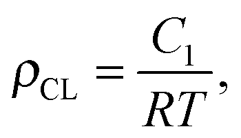
1H- and 13C-NMR spectra were recorded at 298 K on a Bruker Avance 400 NMR spectrometer using a 5 mm broadband inverse probe at 400.13 and 100.61 MHz, respectively. Chemical shifts (δ) in ppm were calibrated to residual solvent peaks (CDCl3: δ = 7.26 and 77.16 ppm, D2O δ = 4.79). Size exclusion chromatograms were recorded using an Agilent 1100 Series HPLC (Columns: serial coupled PSS SDV 5 μ, 100A and PSS SDV 5 μ, 1000A, detector: DAD, 235 nm and 360 nm; refractive index), with THF as mobile phase. PDMS standards were used for the calibration and toluene as an internal standard. Swelling-extraction tests were conducted by immersing the samples in THF at room temperature for 5 days. Every 24 h the solvent was replaced. The films were dried to constant mass at 50 °C under reduced pressure. IR spectra were recorded on a Bruker Tensor 27 FT-IR using either an ATR setup or as KBr pellet. The tensile tests were performed on a Zwick Z010 tensile test machine with a crosshead speed of 50 mm min−1 (278% min−1). Tensile test specimens with a gauge width of 2 mm and a gauge length of 18 mm were prepared by die cutting. The strain was determined using a longitudinal strain extensometer. The curves were averaged from 3 different samples per material (see ESI†). The tensile modulus was determined from the slope of the stress–strain curves using a linear fit to the data points within 10% strain. Crosslink density was determined according to the literature.24,25 The averaged tensile test values were used for the calculation. The intercept C1 of a linear fit for 1/λ values between 0.8 and 0.55 in the σ/(λ − λ−2) vs. 1/λ plot was determined. The crosslinking density was calculated aswhere R is the gas constant and T the temperature. Dynamic mechanical analysis was carried out on a RSA 3 DMA from TA Instruments. Stripes of 10 mm × 20 mm were measured under a dynamic load of 2.5 g, at 2% strain in the frequency range of 0.05–10 Hz at 25 °C and 65% humidity. Permittivity measurements were performed in the frequency range from 1 Hz to 1 MHz using a Novocontrol Alpha-A frequency analyzer. The VRMS (root mean square voltage) of the probing AC electric signal applied to the samples was 1 V. The samples were squeezed between two electrodes (diameter of 5 mm). The electromechanical tests were performed using circular membrane actuators, for which the films were fixed between two circular frames. A biaxial prestrain of 28.6% was used. Circular electrodes (8 mm diameter) of carbon black powder were applied to each side of the film. A FUG HCL-35-12500 high voltage source served as power supply for actuator tests. The voltage was increased by 50 V steps every 2 s up to breakdown. The actuation strain was measured optically as the extension of the diameter of the electrode area via a digital camera, using an edge detection tool of a LabView program to detect the boundary between the black electrode area and the transparent silicone film. The dielectric breakdown field (Eb) of the films was measured by placing the films between two flat electrodes with a 1 mm2 area which were embedded in an epoxy resin. The voltage was gradually increased until the breakdown occurred.
2.3. Synthesis of 2-cyanoethylthiouronium hydrochloride
To a solution of thiourea (57.5 g, 0.755 mol, 1.37 equiv.) in water (38 ml), 3-chloropropionitrile (49.3 g, 0.551 mol, 1 equiv.) was added and heated to 100 °C for 2 h. The reaction mixture was cooled in an ice/salt bath to crystallize the product. The precipitate was dispersed in acetone (160 ml) and then filtered. The filter cake was washed with cold acetone and ether and dried under reduced pressure to yield 2-cyanoethylthiouronium hydrochloride as white crystals (78.9 g, 0.476 mol, 86%). 1H NMR (400 MHz, D2O, δ): 3.47 (t, J = 6.72 Hz, 2H, S–CH2); 3.02 (t, J = 6.72 Hz, 2H, CH2–CN).2.4. Synthesis of 1-mercaptopropionitrile (2)26
An aq. NaOH sol. (11.2 M, 78 ml, 0.874 mol, 1.8 equiv.) was added dropwise to a solution of 2-cyanoethylthiouronium hydrochloride (78.9 g, 0.476 mol, 1 equiv.) in water (210 ml) under Ar at 15–25 °C. It was then heated to 45 °C for an additional 1 h. The reaction mixture was cooled in an ice/salt bath, H2SO4 (ca. 14 ml) was added to adjust the pH to 6, and the solution was then extracted with diethyl ether (6 × 100 ml). The combined organic phases were dried over MgSO4, filtrated, and the solvent was removed. The reaction mixture was distilled to give a colourless liquid (19.6 g, 0.225 mol, 47%). 1H NMR (400 MHz, CDCl3, δ): 2.82–2.76 (m, 2H, S–CH2); 2.71–2.67 (m, 2H, CH2–CN); 1.80 (t, J = 8.5, 1H).2.5. Synthesis of materials M(x![[thin space (1/6-em)]](https://www.rsc.org/images/entities/h3_char_2009.gif) :y)
:y)
A suspension of functionalized SiO2 nanoparticles (231 mg) in THF (10 ml) was sonicated for 5 min using an ultrasonicator tip. To this, poly(methylvinylsiloxane) (2.00 g, 23.2 mmol, 1 equiv.) was added and stirred until it dissolved. Thiols 1 (1.01 g, 11.2 mmol, 0.48 equiv.), 2 (0.98 g, 11.2 mmol, 0.48 equiv.) and 3 (28 μl, 0.17 mmol, 0.007 equiv.), and DMPA (14 mg, 0.05 mmol, 0.002 equiv.) were added and the mixture was stirred to form a homogenous solution. The reaction mixture was poured on a Teflon substrate and covered with a glass plate, whereby two 300 μm spacers were used to adjust the thickness of the film. The film formed after UV-irradiation for 4 min was dried at 50 °C for 24 h.
3. Results and discussion
A series of silicone elastomers containing polar CN pendant groups was prepared in a one-step process as shown in Scheme 1. To ensure good mechanical properties for the cross-linked materials and a maximum degree of modification with CN groups, a high molecular weight polysiloxane P that contains vinyl groups at every siloxy repeat unit was used as the starting material. Polymer P was synthesized in a 200 g batch by anionic polymerization of 1,3,5,7-tetramethyl-1,3,5,7-tetravinylcyclotetrasiloxane (V4) in the presence of tetramethylammonium hydroxide (TMAH) following standard procedures and was used as the stock for subsequent materials formation. The molecular weight and its distribution (Mn = 85 kg mol−1, Mw = 209 kg mol−1, and D = 2.46) were determined by GPC in tetrahydrofuran (THF) using poly(dimethylsiloxane) standards. The vinyl groups of polysiloxane P served two purposes: attaching polar CN groups and cross-linking two polysiloxane chains via a bifunctional thiol. For the modification of P with polar groups, a wide range of polar thiols can in principle be used. We selected 3-mercaptopropionitrile (2) because it is easily accessible in large quantities from rather cheap materials and it contains polar CN groups which are easy to polarize by an electric field.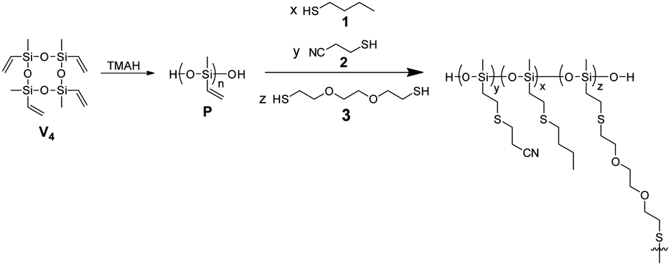 | ||
| Scheme 1 Synthesis of poly(methylvinylsiloxane) P from V4 monomer and in situ functionalization and cross-linking of P with butanethiol/3-mercaptopropionitrile and 2,2′-(ethylenedioxy)diethanethiol, respectively, via an UV-induced thiol–ene reaction. | ||
To tune the amount of CN groups, P was reacted with 1-butanethiol (1) and 2 separately and in various ratios x![[thin space (1/6-em)]](https://www.rsc.org/images/entities/char_2009.gif) :y, as well as with the dithiol 3 cross-linker so as to create materials M(x:y) with different contents of CN groups (y). The amount of cross-linker 3 used has a direct impact on the mechanical properties of M(x:y). In a typical experiment a solution of P, an approximately equimolar amount of functional thiols (1, 2 or a mixture of 1:2), the selected amount of dithiol cross-linker 3, and DMPA were placed between a glass plate and a Teflon substrate. The distance between the plates was adjusted by spacers. During UV-irradiation, the dipole attachment and the cross-linking in thin films occur simultaneously. The top glass plate was immediately removed after irradiation, and the films were carefully peeled off from the glass plate (Fig. 1). All films yielded elastic materials upon cross-linking.
:y, as well as with the dithiol 3 cross-linker so as to create materials M(x:y) with different contents of CN groups (y). The amount of cross-linker 3 used has a direct impact on the mechanical properties of M(x:y). In a typical experiment a solution of P, an approximately equimolar amount of functional thiols (1, 2 or a mixture of 1:2), the selected amount of dithiol cross-linker 3, and DMPA were placed between a glass plate and a Teflon substrate. The distance between the plates was adjusted by spacers. During UV-irradiation, the dipole attachment and the cross-linking in thin films occur simultaneously. The top glass plate was immediately removed after irradiation, and the films were carefully peeled off from the glass plate (Fig. 1). All films yielded elastic materials upon cross-linking.
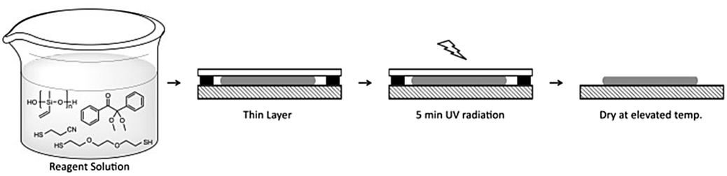 | ||
| Fig. 1 A one-step process to prepare silicone elastomer films with tuneable content of CN groups. A solution of P, 2,2′-(ethylenedioxy)diethanethiol cross-linker, different ratios of functional thiols (butanethiol:3-mercaptopropionitrile), and DMPA UV-initiator in THF was placed between two glass plates and UV-irradiated to form elastic films. | ||
Since we wanted to keep the amount of cross-linker constant for all materials, the optimum concentration that allowed the formation of elastomers irrespective of the CN group content had to be found. This concentration was optimized for the most challenging material, which turned out to be the one which had only butyl thioether groups M(1:0). As mentioned in the Introduction, the synthesis of a material fully functionalized with CN groups was recently described by us, and therefore the reported recipe was used as the starting point for our investigations. When material M(1:0) was prepared using the reported recipe, except that thiol 2 was replaced by 1, a rather brittle material with low strain at break formed. Therefore, we gradually decreased the amount of 3 from 23 μl to 10 μl per g of P. The stress–strain curves of the resulting materials are shown in Fig. 2, while the amounts of reagents used are given in Table 1. All materials showed a strain at break of more than 100%. As expected, the materials turned softer with the decreasing amount of cross-linker since the cross-link density is decreased. The best material of composition M(1:0) had a strain at break of 190% and a tensile strength of 122 kPa (Fig. 2). A small improvement in the mechanical properties of M(1:0) was achieved when 5 wt% of hexamethyldisilazane treated silica particles were used.
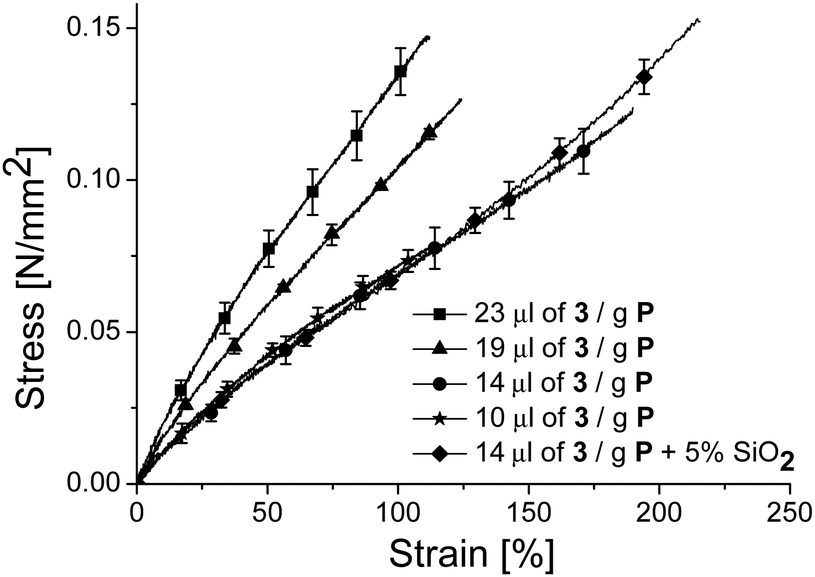 | ||
| Fig. 2 Stress–strain curves of material M(1:0) for which the amount of bifunctional thiol cross-linker 3 was tuned. Each curve is the average of three samples (see ESI†). | ||
:y)
| Name | P [g] | 1 [g] | 2 [g] | 3 [μl] | SiO2 [wt%] | THF [ml] | Spacer μm |
|---|---|---|---|---|---|---|---|
|
M(1:0)
|
1 | 1.00 | — | 23 | — | 4 | 300 |
|
M(1:0)
|
1 | 1.00 | — | 19 | — | 4 | 300 |
|
M(1:0)
|
1 | 1.00 | — | 14 | — | 4 | 300 |
|
M(1:0)
|
1 | 1.00 | — | 10 | — | 4 | 300 |
|
M(1:0)
|
1 | 1.00 | — | 14 | 4.8 | 5 | 300 |
|
M(3:1)
|
2 | 1.52 | 0.49 | 28 | 4.8 | 10 | 300 |
|
M(1:1)
|
2 | 1.01 | 0.98 | 28 | 4.8 | 10 | 300 |
|
M(1:3)
|
2 | 0.50 | 1.45 | 28 | 4.8 | 10 | 300 |
|
M(0:1)
|
2 | — | 1.96 | 28 | 4.8 | 10 | 300 |
For the synthesis of materials M(x:y) the amount of 3 was kept constant (14 μl per g P) (Table 1) and a dispersion of hexamethyldisilazane treated silica particles in THF was used, as it is known that silica particles can reinforce the silicones and increase their strain at break. The amount of silica was kept below 5% so that the elastic moduli are not much affected.
The conversion of the vinyl groups in the films was investigated by FT-IR measurements conducted on the two surfaces as well as with the pellets obtained by pressing the powders of ground films in KBr. The spectra were normalized to the highest peak assigned to the Si–O–Si st vibration at 1025 cm−1. For the vinyl group three characteristic signals at ν = 3055 cm−1, 3020 cm−1 and 2965 cm−1 with the one at 3055 cm−1 having the highest intensity can be easily identified. The signal at ν = 2250 cm−1 is characteristic of the CN groups. With the increasing dipole content, the intensity of the C![[triple bond, length as m-dash]](https://www.rsc.org/images/entities/char_e002.gif) N st band at 2250 cm−1 increased, while that of the C–H st bands at 2956 and 2929 cm−1 decreased. When covering the thin film with a glass plate during irradiation, the IR spectra clearly showed an elevated conversion of the vinyl groups. The IR spectra of the pellets obtained by pressing the powders of ground films in KBr show the presence of less than 4% unreacted vinyl groups. Some residual vinyl groups were expected, since a slightly less than stoichiometric amount of thiols to vinyl groups was used. However, as compared with our previous report23 where the film surface exposed to air had most of the vinyl groups unreacted, here, the top surface covered by the glass plate had most of the vinyl groups reacted (Fig. S1, ESI†).
N st band at 2250 cm−1 increased, while that of the C–H st bands at 2956 and 2929 cm−1 decreased. When covering the thin film with a glass plate during irradiation, the IR spectra clearly showed an elevated conversion of the vinyl groups. The IR spectra of the pellets obtained by pressing the powders of ground films in KBr show the presence of less than 4% unreacted vinyl groups. Some residual vinyl groups were expected, since a slightly less than stoichiometric amount of thiols to vinyl groups was used. However, as compared with our previous report23 where the film surface exposed to air had most of the vinyl groups unreacted, here, the top surface covered by the glass plate had most of the vinyl groups reacted (Fig. S1, ESI†).
The densities of M(x:y) were measured via hydrostatic weighting in ethanol. The materials get denser with the increasing content of nitrile groups from 1.084 g cm−3 for M(1:0), to 1.118 g cm−3 for M(1:1), and reached a maximum value of 1.180 g cm−3 for M(0:1).
The swelling–extraction tests show that all materials contain about 10% extractable species, except for M(1:0) for which the amount of extractable species was 13.4%. The crosslink density was determined by the Mooney–Rivlin equation using the data obtained from the stress–strain experiments. In principle, the Flory–Rhener model could also be used, if the Flory–Huggins interaction parameter of materials M(x:y) were known. It was found that M(1:0) has the lowest cross-link density of 18 mol m−3, which explains the slightly higher extraction fraction observed for this material, while the cross-link density for all other materials was between 21 and 26 mol m−3 (Table 2).
:y)
| Sample |
M(1:0)
|
M(3:1)
|
M(1:1)
|
M(1:3)
|
M(0:1)
|
|---|---|---|---|---|---|
| a Calculated using the Mooney–Rivlin equation [mol m−3]. b Calculated using the amount of starting materials [mol m−3]. | |||||
| Density [g cm−3] | 1.084 | 1.097 | 1.118 | 1.154 | 1.180 |
| Extraction loss [%] | 13.4 | 10.4 | 8.8 | 10.0 | 11.1 |
| XL densitya | 18 | 24 | 25 | 21 | 26 |
| XL densityb | 63 | 63 | 65 | 67 | 68 |
The thermal stability of M(x:y) was investigated by TGA (Fig. S2, ESI†). All materials are stable up to 160 °C where a small amount of volatiles is removed, while above 300 °C the materials lose more than half of their weight. Differential scanning calorimetry (DSC) measurements show an increase in Tg with the increasing mol% of nitrile groups from −92.6 °C for M(1:0) to −67.7 °C for M(1:1), and reached a maximum value of −49.2 °C for M(0:1) (Fig. 3 and Fig. S3, ESI†). No melting points and no other transitions were observed. Table 3 summarizes the transition temperatures observed for M(x:y) as well as the ΔCp of the transitions. Despite the shift of Tg towards higher values due to the chemical modification of P with CN groups, the Tg of all materials was well below room temperature. The increase in Tg and ΔCp with the CN content suggests the presence of some dipole–dipole interactions which restrict the mobility of the polysiloxane segments.
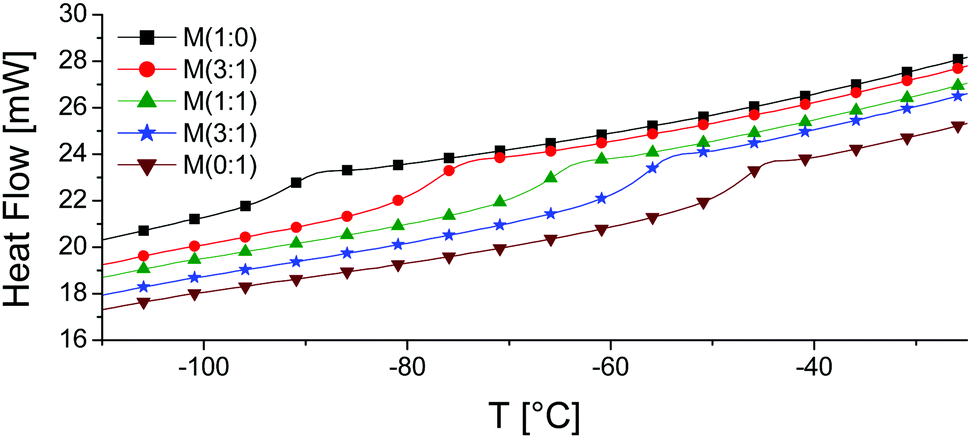 | ||
| Fig. 3 DSC curves of M(x:y). An increase in Tg with the CN content can be seen. | ||
:y) as well as the ΔCp of the transitions
| Material | T g [°C] | ΔCp [J g−1 °C−1] | ||
|---|---|---|---|---|
| 2nd Heating | Cooling | 2nd Heating | Cooling | |
|
M(1:0)
|
−92.6 | −102.3 | 0.30 | 0.31 |
|
M(3:1)
|
−78.3 | −88.3 | 0.35 | 0.37 |
|
M(1:1)
|
−67.7 | −75.2 | 0.38 | 0.46 |
|
M(1:3)
|
−58.2 | −65.5 | 0.44 | 0.43 |
|
M(0:1)
|
−49.2 | −56.5 | 0.44 | 0.45 |
Tensile and DMA investigations were conducted on all materials M(x:y). Fig. 4 shows the stress–strain curves of different materials. It can be seen that the elastomers get stiffer with the increasing amount of CN groups incorporated and the strain at break and the tensile strength increase. All materials were prepared using the same batch of starting polymer and the same amount of cross-linker, the only parameter changed was the ratio of thiols 1 and 2. Therefore, the change in the mechanical properties of M(x:y) can be attributed to the presence of CN groups. The reason behind this is the dipole–dipole interactions which slightly hinder the slipping of the segments, and therefore more stress is needed to deform the materials. The hindered freedom of segment motion is reflected by the increase in the Tg and ΔCp and also reported in the literature.27,28 Sample M(1:0) is the softest very likely due to its lower cross-link density and the plasticising effect of butyl groups. Because M(1:0) does not contain CN groups large segments can move over each other under a mechanical stress. The elastic moduli at different strain levels are summarised in Table 4. The moduli increase from 89 kPa for M(1:0) to 97 kPa for M(1:1) and reach a maximum value of 155 kPa for M(0:1). The strain at break of the films rose from about 210% for M(1:0) to 290% for M(1:1) up to about 320% for M(0:1). The positive increase in the strain at break observed for M(0:1) is mostly due to the dipole–dipole interactions which hinder to some extent the crack propagation.29
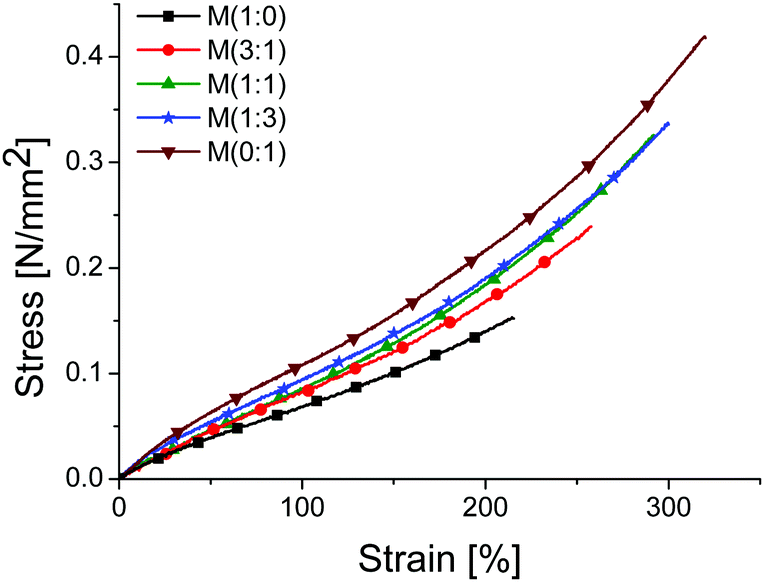 | ||
| Fig. 4 Stress–strain curves for materials M(x:y) from standard tensile tests at 50 mm min−1. The stress–strain curves were averaged from three independent tests. | ||
:y)
Stress–strain curves obtained from standard tensile tests at various initial strain rates (0.463 s−1, 0.0463 s−1, 0.00463 s−1, and 0.00463 s−1) overlapped and an increase in the strain at break with the increasing strain rate was observed for all materials (see ESI†). The increased strain at break at higher initial strain rates might be related to increased creeping in the materials at higher rates. To elucidate this, dynamic mechanical frequency sweep measurements between 0.05 and 10 Hz for M(x:y) were also conducted (Fig. 5). The measurements turned noisier above 3 Hz, indicating that the elastomer cannot follow the modulated amplitude. Nevertheless, the max tan(δ) values at about 6 Hz were below 0.4, a sign that the materials did not yet reach the viscoelastic regime and are still elastic. For all materials, the storage moduli E′ at 0.05 Hz range between 100 kPa and 110 kPa and they only slightly increase with an elevated content of nitrile groups. M(1:0) shows only a minor dependence of E′ and tan(δ) on the strain rate, while M(0:1) shows a significant dependence of E′ on the strain rate. For example, an increase in E′ from 110 kPa at 0.05 Hz to 195 kPa at 5 Hz was observed for material M(0:1) that has the highest content of nitrile groups. An increase of tan(δ) with frequency and with the increasing content of nitrile groups was noted. For example, the tan(δ) of M(0:1) changed from 0.08 at 0.05 Hz to 0.39 at 5 Hz. The storage modulus at low frequencies and the Young's modulus at low strains from the tensile test are quite similar (Table 4).
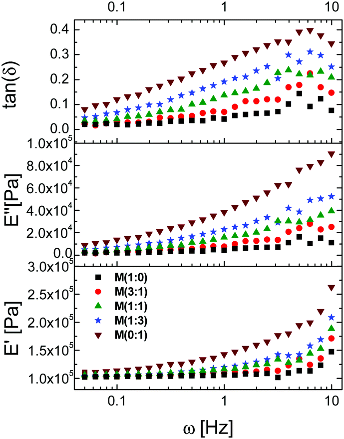 | ||
| Fig. 5 Dynamic mechanical analysis for M(x:y) at different frequencies. | ||
The permittivity of M(x:y) was tuned by reacting different ratios of mercaptopropionitrile/butanethiol with P. As expected, a linear increase in permittivity ε′ with the increasing content of nitrile groups was observed. The ε′ values at high frequencies increased from 4.3 for M(1:0)via 9.7 for M(1:1) to the maximum of 17.4 for M(0:1), which has a CN group at every repeat unit (Fig. 6).
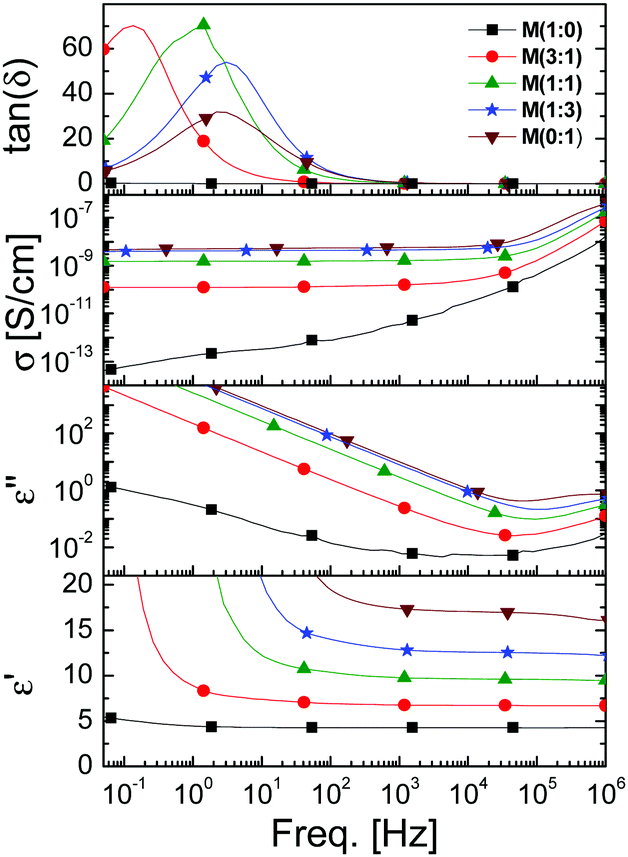 | ||
| Fig. 6 Dielectric properties as a function of frequency of M(x:y). | ||
The improved process to form thin films has a direct influence on their dielectric properties. For example, when we aimed at elastomers with the maximum content of CN groups, M(0:1), the film where one surface was exposed to air showed a permittivity value of 10.1 at 10 kHz and a relaxation peak at 500 Hz that resulted in a further increase in permittivity,23 while the film cured by the optimized method allowed the formation of M(0:1) with permittivity as high as ε′ = 17.4 at 10 kHz.30 A surge in permittivity at low frequencies for all materials modified with CN groups was observed. This increase is very likely due to electrode polarization, when ion impurities accumulate at the electrode. This effect is higher for the materials that have a high content of CN groups and is shifted towards higher frequencies. Unfortunately, the dielectric losses ε′′ increase at higher dipole contents. A similar behaviour was observed for the conductivity σ. For example, material M(1:0) has a σ = 3.5 × 10⁻¹¹ S cm−1 at 10 kHz, while M(0:1) reached a value of σ = 6 × 10⁻⁹ S cm−1, values that are still typical for insulators. The increase in conductivity with the CN content is mainly due to increased ion mobility which is favoured by the presence of CN groups. It is still unclear how the materials got contaminated with ions and if it is possible to avoid them by using ultra-pure reagents, solvents, and glassware. Further work is required to elucidate this aspect.
All materials M(x:y) as well as two commercial reference materials silicone Elastosil and VHB foil were evaluated regarding their actuation strain at different electric fields using circular actuators having 8 mm diameter carbon black electrodes. A biaxial prestrain of 28.6% was applied to all samples to avoid wrinkling of the electrode during actuation, except for VHB where 300% biaxial prestrain was used. The changes in the electrode diameter were measured while the voltage was increased (see the Experimental section). Fig. 7 shows the lateral actuation strain as a function of electric field for different materials M(x:y). The actuation as a function of electric field and the stress–strain curves of Elastosil, VHB, and M(x:y) are given in the ESI.†
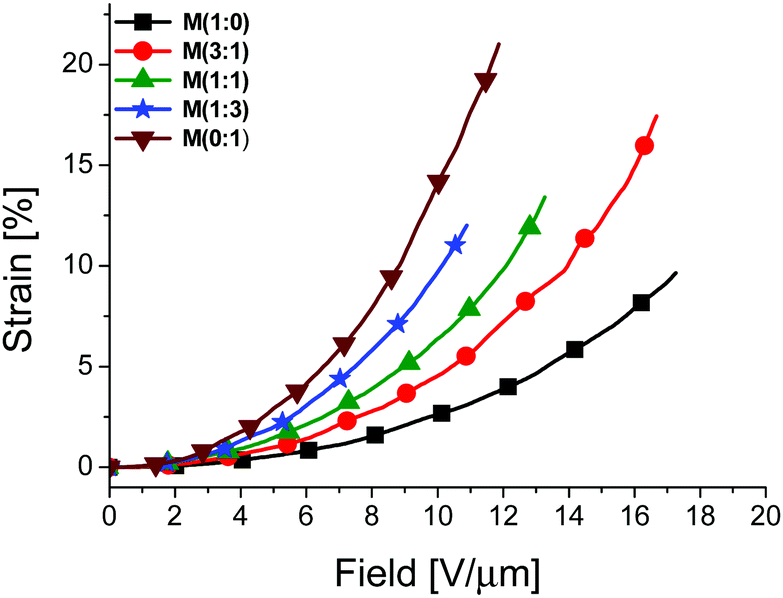 | ||
| Fig. 7 Lateral actuation strain as a function of electric field for materials M(x:y) which were 28.6% biaxially prestrained. The curves were averaged from two independent tests, except for M(3:1) for which only one measurement was conducted. | ||
Table 5 summarizes the dielectric permittivity, Y30%, electromechanical sensitivity ε′/Y10%, the actuation at different electric fields, some dielectric characteristics of materials M(x:y) as well as of two commercial materials. For all materials two independent actuation tests were conducted except for M(3:1) for which only one actuator was measured. All materials, except for VHB actuated at electric fields lower than 20 V μm−1 whereby M(0:1) showed the largest actuation of 21% at the lowest field of 11.9 V μm−1. Despite the slight increase in the elastic moduli at higher nitrile contents in M(x:y), a rise of the actuation strain at a certain voltage with the increasing content of polar groups was observed. For example, at an electric field of 10 V μm−1, M(1:0) exhibits 2.7% strain, M(1:1) gave 6.4% strain, and M(0:1) reached a maximum actuation strain of 14.1%. The reason behind the low electric field required for actuating M(x:y) is the strong increase in permittivity for these materials, and therefore an increase in electromechanical sensitivity. It is generally accepted that the actuation strain increases with increasing ε′/Y values. Despite the lower elastic modulus of the two commercial materials, the silicone Elastosil and the acrylic VHB foil as compared to M(x:y), their actuation strain is rather low. This is caused by low permittivity, and therefore low ε′/Y values. Novel, chemically modified silicone based materials reported in the literature also show reduced driving voltages at increased ε′/Y values which are mainly caused by a moderate increase of permittivity and a decrease of elastic modulus.17–19,31–33 This decrease with the increasing content of polar groups in the material is somewhat surprising as one would normally expect an increase in stiffness caused by the dipolar interactions.29 The reason for this unexpected observation is a reduced cross-linking degree caused by the polar groups which resulted in a softer material.
:y)
| Material | CN groups [mol%] | ε′ @ 1 kHz | Y 10% [N mm−2] | ε′/Y10% | s [%] | E [V μm−1] | s max [%] | E b,act [V μm−1] | E b [V μm−1] | β | η | R 2 |
|---|---|---|---|---|---|---|---|---|---|---|---|---|
| a Lateral actuation strain at 10 V μm−1. b Electric field used to induce 9.7% lateral actuation strain. c E b was determined by placing the dielectric film between electrodes of 1 mm2 area. d wt% of DR19 in materials is given. e The elastic moduli at small strains.34 | ||||||||||||
|
M(1:0)
|
0 | 4.3 | 0.089 | 47.8 | 2.7 | 17.3 | 9.7 | 23 | 33.8 ± 4.3 | 9.4 | 35.6 | 0.87 |
|
M(3:1)
|
25 | 6.8 | 0.096 | 68 | 4.6 | 13.8 | 17.5 | 18 | 27.0 ± 2.5 | 12.0 | 28.1 | 0.96 |
|
M(1:1)
|
50 | 9.8 | 0.097 | 81.7 | 6.4 | 11.9 | 13.5 | 13 | 21.2 ± 2.5 | 9.4 | 22.3 | 0.94 |
|
M(1:3)
|
75 | 12.9 | 0.128 | 92.1 | 9.6 | 10.0 | 12.0 | 11 | 19.4 ± 2.7 | 8.1 | 20.5 | 0.91 |
|
M(0:1)
|
100 | 17.4 | 0.155 | 116 | 14.1 | 8.7 | 21.0 | 12 | 15.6 ± 1.9 | 8.6 | 16.4 | 0.96 |
| Elastosil | — | 3 | 0.09 | 33.3 | 0.7 | — | 6 | 25 | — | — | — | — |
| VHB | — | 4.4 | 0.2 | 22 | 0 | 68 | — | — | — | — | — | — |
| E-DR19 | 0%d | 2.72 | 0.268e | 10.1 | <1.5% | — | 4.3 | 53.1 | — | — | — | — |
| E-DR19 | 1.2%d | 3.05 | 0.296e | 10.3 | <1.5% | — | 7.2 | 58.8 | — | — | — | — |
| E-DR19 | 4%d | 3.95 | 0.309e | 12.8 | <1.5% | 63.4 | 10.3 | 64.7 | — | — | — | — |
| E-DR19 | 7.1%d | 4.64 | 0.325e | 14.1 | <1.5% | 57.8 | 17.6 | 68.2 | — | — | — | — |
| E-DR19 | 10.3%d | 4.82 | 0.367e | 13.1 | <1.5% | 54.2 | 11.7 | 56.8 | — | — | — | — |
| E-DR19 | 13.3%d | 4.88 | 0.725e | 6.7 | <1.5% | NA | 6.2 | 53.9 | — | — | — | — |
A recent comprehensive overview regarding the performance of different polar silicone materials by Madsen et al. is available.4 Here, we compare our results with materials reported by Zhang et al. which behave similar to ours and where actuation tests were performed. Their silicone elastomers were modified with Disperse Red 19.34 An increase in permittivity from 2.72 to 4.88 and an increase in elastic modulus from 268 kPa to 725 kPa with the increasing content of DR19 were observed (Table 5). The ε′/Y values increase with the content of DR19 up to a concentration of 10.3 wt% when a decrease of the ε′/Y value was observed. Above this concentration, the actuation performance deteriorated. In our materials, no such saturation was observed, e.g. the ε′/Y values gradually increase with the nitrile content which is reflected in a linear increase in the actuation strain. In addition, our materials show significantly higher ε′/Y values. An actuation strain as high as 21% at an electric field as low as 11.9 V μm−1 was achieved, while the DR19 modified materials reach a maximum actuation strain of 17% at significantly higher electric fields of about 68.2 V μm−1.
The dielectric breakdown field (Eb) of the films was also measured. As expected, the higher the dipole content in M(x:y), the lower the dielectric breakdown. This trend was also observed in actuator tests, except that the Eb values in actuators are slightly lower given the fact that the electrode area was significantly larger (∼50 mm2), and therefore the probability of failure increased.
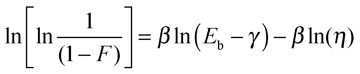
The influence the CN content in the materials M(x:y) has on the dielectric breakdown field was further investigated using Weibull statistics using eqn (1)
 | (1) |
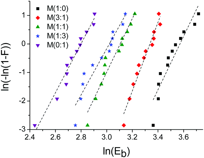 | ||
| Fig. 8 Weibull plot for different materials M(x:y). The dashed lines represent the linear fit to the data. | ||
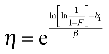
Since the points are in good agreement with the linear fit, the Weibull location parameter γ was neglected. Sample M(1:0) is an exception (R2 = 0.87) because the points might fit better to a concave curve which might suggest that γ has to be considered. The corresponding calculations of sample M(1:0) for which γ ≠ 0, can be found in the ESI.† The Weibull shape parameter β corresponds to the slope of the linear fit and gives information about the shape of the distribution. The β values lie in a narrow range between 8.1 and 12.0 indicating a similar shape of the distribution for all materials. The Weibull scale parameter η was determined for F = 0.632, were η is equal to Eb and can therefore easily be calculated using eqn (2):
 | (2) |
:0) to 22.3 V μm−1 for M(1:1) to 16.4 V μm−1 for M(0:1). Despite the reduction of the breakdown field and the increase of the elastic moduli with the CN content, the maximum actuation strain of 21% at 12 V μm−1 is about two times higher as compared to the actuation strain of 9.7 at an almost double electric field of 23 V μm−1 for material M(0:1) which has no CN groups. The large actuation strain of M(0:1) is highly attractive since this opens the access to actuators operable below 100 V with dielectric films of 10 μm. Work in this direction is on the way.
4. Conclusions
Polysiloxane elastomers with different contents of polar nitrile groups and about the same degree of chemical cross-linking were prepared in a one-step process starting from a high molecular weight poly(methylvinylsiloxane) by using thiol–ene photo-addition of butanethiol (1), 3-mercaptopropionitrile (2) or a mixture thereof, and the 2,2′-(ethylenedioxy)diethanethiol (3) cross-linker to the vinyl groups. The resulting elastomers were characterized by IR, tensile tests, DMA, TGA, DSC, impedance spectroscopy as well as by electromechanical tests using circular actuators. An increase in stiffness, strain at break, and tensile stress with the increasing content of polar nitrile groups in the elastomers with a maximum elongation at break of 320% for an elastomer that contained the maximum amount of nitrile groups was observed. DMA shows an increase in stiffness with the increasing content of polar groups and low viscoelastic losses at low frequency. The mechanical losses at high frequencies increase with the increasing content of nitrile groups but stay below 0.4. TGA shows that the elastomers are stable up to 300 °C, while according to DSC these elastomers have a Tg well below room temperature. Impedance spectroscopy investigations show that the permittivity can be fine-tuned from ε′ = 4.3 for the elastomer modified only with butanethiol to the maximum value of ε′ = 17.4 for the elastomer that has the maximum content of nitrile groups. All other elastomers lie within this range. Electromechanical tests showed that the actuation field is significantly reduced for the nitrile modified elastomers. For example, the actuation strain at 10 V μm−1 of the material modified with 1 was 2.7%, increased to 6.4% for an elastomer modified with a 1:1 mixture of thiols 1 and 2, and reached a value of 14.1% for the elastomer containing the maximum amount of nitrile groups. The actuation strain of 21% at about 12 V μm−1 of the material that is fully functionalized with CN groups is highly attractive since this opens the possibility of constructing actuators operable below 100 V with dielectric films whose thickness is below 10 μm. Low driving voltage actuators are highly attractive since the electronics required to drive them are simpler and cheaper. Work in this direction is on the way.
Acknowledgements
We gratefully acknowledge the Swiss National Science Foundation (SNF132101, Swiss-Romanian Cooperation Program, grant no. IZERZO_142215/1) and Swiss Federal Laboratories for Materials Science and Technology (Empa, Dübendorf) for financial support. We also acknowledge B. Fischer for DSC and TGA measurements, C. Walder and T. Künniger for their help with the DMA measurements, and Dr G. Kovacs for providing us with the infrastructure for the actuator measurements (all Empa). Many thanks to Prof. Z. M. Dang from Tsinghua University, Beijing, for providing us with the data of his materials.Notes and references
- R. Pelrine, R. Kornbluh, Q. Pei and J. Joseph, Science, 2000, 287, 836–839 CrossRef CAS PubMed.
- W. Hu, S. N. Zhang, X. Niu, C. Liu and Q. Pei, J. Mater. Chem. C, 2014, 2, 1658–1666 RSC.
- J. E. Q. Quinsaat, M. Alexandru, F. A. Nüesch, H. Hofmann, A. Borgschulte and D. M. Opris, J. Mater. Chem. A, 2015, 3, 14675–14685 CAS.
- F. B. Madsen, A. E. Daugaard, S. Hvilsted and A. L. Skov, Macromol. Rapid Commun., 2016, 37, 378–413 CrossRef CAS PubMed.
- A. O'Halloran, F. O'Malley and P. McHugh, J. Appl. Phys., 2008, 104, 071101 CrossRef.
- R. E. Perline, R. D. Kornbluh and J. P. Joseph, Sens. Actuators, A, 1998, 64, 77–85 CrossRef.
- D. M. Opris, S. Dünki, C. Racles, A. Bele and M. Cazacu, PCT Int. Appl., WO 2015135086 A1 20150917, 2015 Search PubMed.
- M. Stepp, F. Achenbach and A. Koellnberger, WO 2015/121261 Al, 2015.
- D. M. Opris and S. Dünki, Chimia, 2015, 69, 549 CrossRef.
- D. M. Opris, J. E. Q. Quinsaat, S. Dünki, Y. S. Ko, M. Alexandru, C. Racles and F. A. Nüesch, Proc. SPIE, 2015, 94300A Search PubMed.
- P. Brochu and Q. Pei, Macromol. Rapid Commun., 2010, 31, 10 CrossRef CAS PubMed.
- R. Shankar, T. K. Ghosh and R. J. Spontak, Adv. Mater., 2007, 19, 2218–2223 CrossRef CAS.
- L. Maffli, S. Rosset, M. Ghilardi, F. Carpi and H. Shea, Adv. Funct. Mater., 2015, 25, 1656 CrossRef CAS.
- L. J. Romasanta, M. A. Lopez-Manchado and R. Verdejo, Prog. Polym. Sci., 2015, 51, 188 CrossRef CAS.
- F. B. Madsen, L. Yu, A. E. Daugaard, S. Hvilsted and A. L. Skov, RSC Adv., 2015, 5, 10254 RSC.
- F. B. Madsen, L. Yu, A. E. Daugaard, S. Hvilsted and A. L. Skov, Polymer, 2014, 55, 6212 CrossRef CAS.
- A. Risse, B. Kussmaul, H. Krüger and G. Kofod, Adv. Funct. Mater., 2012, 22, 3958–3962 CrossRef.
- B. Kussmaul, S. Risse, G. Kofod, R. Wache, M. Wegener, D. N. McCarthy, H. Krüger and R. Gergard, Adv. Funct. Mater., 2011, 21, 4589–4594 CrossRef CAS.
- H. Böse, D. Uhl and R. Rabindranath, Proc. SPIE, 2012, 8340, 83402E CrossRef.
- A. H. A. Razak, P. Szabo and A. L. Skov, RSC Adv., 2015, 5, 53054 RSC.
- S. J. Dünki, M. Tress, F. Kremer, S. Y. Ko, F. A. Nüesch, C.-D. Varganici, C. Racles and D. M. Opris, RSC Adv., 2015, 5, 50054–50062 RSC.
- C. Racles, M. Alexandru, A. Bele, V. E. Musteata, M. Cazacu and D. M. Opris, RSC Adv., 2014, 4, 37620–37628 RSC.
- S. J. Dünki, Y. S. Ko, F. A. Nüesch and D. M. Opris, Adv. Funct. Mater., 2015, 25, 2467–2475 CrossRef.
- M. Mooney, J. Appl. Phys., 1940, 11, 582 CrossRef.
- R. S. Rivlin, Philos. Trans. R. Soc., A, 1948, 241, 379 CrossRef.
- R. E. Gerber, C. Hasbun, L. G. Dubenko, M. F. King and D. E. Bierer, Org. Synth., 2000, 77, 86 Search PubMed.
- Y. Zhang, Y. Li and W. Liu, Adv. Funct. Mater., 2015, 25, 471–480 CrossRef CAS.
- T. Bai, P. Zhang, Y. Han, Y. Liu, W. Liu, X. Zhao and W. Lu, Soft Matter, 2011, 7, 2825–2831 RSC.
- S. Thomas, C. H. Chan, L. A. Pothen, K. R. Pajisha and H. L. Maria, Natural Rubber Materials, RSC Publishing, 2014 Search PubMed.
- F. Kremer and A. Schönhals, Boadband Dielectric Spectroscopy, Springer-Verlag, Berlin Heidelberg, 2003 Search PubMed.
- B. Kussmaul, S. Risse, M. Wegener, G. Kofod and H. Krüger, Smart Mater. Struct., 2012, 21, 064005 CrossRef.
- S. Risse, B. Kussmaul, H. Krüger and G. Kofod, RSC Adv., 2012, 2, 9029 RSC.
- M. Dascalu, S. J. Dünki, J.-E. Q. Quinsaat, Y. S. Ko, F. A. Nüesch and D. M. Opris, RSC Adv., 2015, 5, 104516 RSC.
- L. Zhang, D. Wang, P. Hu, J.-W. Zha, F. Yous, S.-T. Li and Z. M. Dang, J. Mater. Chem. C, 2015, 3, 4883–4889 RSC.
- M. Kollosche and G. Kofod, Appl. Phys. Lett., 2010, 96, 12–15 CrossRef.
- IEC 61649:2008.
Footnote |
| † Electronic supplementary information (ESI) available: IR spectra, TGA, DSC curves, and the calculation of the Weibull parameter for M(1:0), stress–strain curves at different strain rates, stress–strain curves and the actuation strain as a function of electric field for Elastosil and VHB. See DOI: 10.1039/c6tc01731b |
| This journal is © The Royal Society of Chemistry 2016 |