 Open Access Article
Creative Commons Attribution 3.0 Unported Licence
Trifluoromethyl-functionalized bathocuproine for polymer solar cells†
Yanfei
Zhao
ab,
Matthias Georg
Schwab
a,
Adam
Kiersnowski
ac,
Wojciech
Pisula
ad,
Martin
Baumgarten
a,
Long
Chen
ae,
Klaus
Müllen
a and
Chen
Li
*a
aMax Planck Institute for Polymer Research, Ackermannweg 10, 55128 Mainz, Germany. E-mail: lichen@mpip-mainz.mpg.de
bDepartment of Chemical and Biological Engineering, Guangxi Normal University for Nationalities, Fozi Road 36, Jiangzhou District, 532200 Chongzuo, China
cPolymer Engineering and Technology Division, Wroclaw University of Technology, WybrzezeWyspianskiego 27, 50-370 Wroclaw, Poland
dDepartment of Molecular Physics, Faculty of Chemistry, Lodz University of Technology, Zeromskiego 116, 90-924 Lodz, Poland
eDepartment of Chemistry, School of Science, Tianjin University, 300072 Tianjin, China
First published on 4th May 2016
Abstract
A novel bathocuproine (BCP) derivative 4,7-bis(3,5-bis(trifluoromethyl)phenyl)-2,9-dimethyl-1,10-phenanthroline (BCP-2CF3) was synthesized and investigated as a candidate for exciton blocking layers (EBLs) in organic solar cells. The impacts of BCP-2CF3 and BCP on the performance of photovoltaic devices were studied for bulk-heterojunction (BHJ) devices with a blend of poly[N-9′′-hepta-decanyl-2,7-carbazole-alt-5,5-(4′,7′-di-2-thienyl-2′,1′,3′-benzothiadiazole)] (PCDTBT) and [6,6]phenyl-C61-butyric acid methyl ester (PC61BM). In comparison with BCP, BCP-2CF3 showed a comparable improvement in the power conversion efficiency (PCE) (ca. 39%), and moreover a better thermal stability. Organic photovoltaic (OPV) devices with BCP-2CF3 withstood an annealing temperature as high as 100 °C, while those with BCP revealed a loss about 90% of the original efficiency at the same temperature. The newly designed principle for BCP-derived EBL materials opens a window for systematic enhancement of the efficiency and especially durability of organic solar cells.
1. Introduction
Organic photovoltaic (OPV) devices have emerged as a new branch of the photovoltaic family due to their advanced properties including low cost, light-weight, mechanical flexibility, easy processability and large-scale production. The power conversion efficiency (PCE) of single junction devices has exceeded 10%,1 which is still not as high as conventional silicon-based cells.2 Hence, endeavors are made to further optimize their performance.3–5 One of which is to design and develop new semiconducting materials. The chemical structures of organic semiconductors can be “well-defined” to synthesize ideal donors and acceptors for bulk-heterojunction (BHJ) devices,5–11 or donor–acceptor co-oligomers for single molecular solar cells.12–15 The bandgaps can be narrowed for high sunlight exploitation efficiency by the enlargement of the π-conjugated systems, transition from aromatic to quinoid resonance forms and integration of donor–acceptor functional units.16–19 The energy levels can be well fitted between donors and acceptors for efficient charge separation at minimum energy loss by the introduction of electron-donating or -accepting groups.20–25 Molecular packing can be controlled to facilitate charge carrier transport by modification of the main structure with suitable side-chains.26–31 Meanwhile, much research has been devoted to device structure optimization. One facile approach is the implementation of anode and/or cathode buffer layers (CBL) to improve the contact properties of organic active layer/electrode interfaces.32–35 An exciton blocking layer (EBL) is one type of cathode buffer layer which prevents the quenching of excitons and holes at the metal electrode. Critical requirements for efficient EBL materials are: (1) conductivity: an electron transporting material is required to ensure a low series resistance;36,37 (2) energetics: it should possess a wide energy gap (Eg) to blockthe diffusion of excitons to the cathode and a highest occupied molecular orbital (HOMO) lower than that of the donor material to block holes; and (3) color: the materials should be colorless to act as a non-absorbing layer to the incident solar radiation.36 Among many candidates satisfying the above three criteria, bathocuproine (BCP),38 bathophenanthroline (BPhen),39 1,3,5-tris(2-N-phenylbenz-imidazolyl) benzene (TPBI),40,41 tris(8-hydroxy-quinolinato)-aluminium (Alq3)41–43 and titanium suboxide (TiOX)44 are the most common EBL compounds. In terms of improving PCE, BCP and BPhen are as efficient as their competitors or even superior.41,45–50 However, the device stability remains a challenge. BCP- and BPhen-based OPVs suffer from aging especially in air and under high temperature conditions.43,51–55 It is reported that BCP thin films readily crystallize in the presence of moisture, oxygen, and heat yielding micron-sized domains.36 Doping BCP with a larger molecule like 3,4,9,10-perylenetetracarboxylicbis-benzimidazole (PTCBI)40 or Alq342 prevented film crystallization, thus extending device lifetime. Since the poor stability of BCP is the bottleneck for its wide application, it is the aim of this work to better understand BCP based EBL materials.A new BCP derivative 4,7-bis(3,5-bis(trifluoromethyl)phenyl)-2,9-dimethyl-1,10-phenanthroline (BCP-2CF3) was synthesized according to the molecular designing concepts as follows: introducing substituents onto the phenyl rings to (1) tune the energy levels, (2) influence the molecular ordering and the ultimate thin film morphology, and (3) tune the crystallization temperature of the compound. BCP-2CF3 and BCP were employed as EBLs in BHJ solar cells with a low bandgap polymer poly[N-9′′-hepta-decanyl-2,7-carbazole-alt-5,5-(4′,7′-di-2-thien-yl-2′,1′,3′-benzothiadiazole)] (PCDTBT) as the donor and [6,6]phenyl-C61-butyric acid methyl ester (PC61BM) as the acceptor. The device efficiency and stability were investigated to gain an understanding of the relationships between the EBL molecular structure, EBL properties and solar cell device performance.
2. Results and discussion
2.1 Synthesis
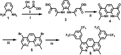
BCP-2CF3 was synthesized according to our previous synthetic method that allows for straightforward access to new BCP compounds.49 A one-step Suzuki-coupling reaction under microwave conditions between commercially available 1,5-ditrifluoromethane-3-phenyl boronic acid and 4,7-dibromo-2,9-dimethyl-1,10-phenanthroline (5)56 allowed the synthesis of the new molecule 6 in 70% yield (Scheme 1). The crude products were purified by silica column chromatography eluted with ethyl acetate to obtain off-white crystalline solids. The starting material 5 was synthesized following a procedure reported in the literature.56 The reaction started with o-phenylenediamine (1), which was mixed with 3-hydroxybut-2-enoate (2) and phosphorous pentoxide at room temperature under reduced pressure in a desiccator for three weeks. Compound 3 was slowly formed under these conditions in 37% yield as an orange oil. After that, intramolecular self-cyclization of 3 was performed in diphenylether under reflux for 30 minutes to produce 4 as a light-brown powder, which was used directly for the next reaction step without purification. To obtain compound 5, a mixture of phosphoryl bromide and 4 was heated under argon at 80 °C for 6 hours. The product was purified by column chromatography to give an off-white solid in 53% yield.2.2 Optical and electrochemical characterization
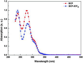
The UV-Vis absorption spectra of BCP and BCP-2CF3 solution are shown in Fig. 1. Relevant data are presented in Table 1. Both materials exhibited very narrow absorption bands from 220 nm to 300 nm in the UV region of the solar emission, which is typically found for 1,10-phenanthroline derivatives.57 Since these EBLs are transparent in the visible region, they have almost no impact on the sunlight absorbed and photocurrent generated by the active layer.| Material | λ max [nm] | λ onset [nm] | E optg [eV] | HOMOopt [eV] | LUMO [eV] |
|---|---|---|---|---|---|
| BCP | 277 | 340 | 3.65 | −6.61 | −2.95 |
| BCP-2CF3 | 239 | 333 | 3.73 | −6.77 | −3.06 |
The electrochemical properties of BCP and BCP-2CF3 were studied by cyclic voltammetry (CV). The lowest unoccupied molecular orbital (LUMO) levels were measured directly from the reduction potentials (Fig. S1 in the ESI†). Because of the large bandgaps, the oxidation waves were beyond the stability window of the solvent used. The HOMO levels were estimated from the optical bandgaps according to the following equations.
| HOMOopt = LUMO − Eoptg (eV) |
2.3 Device performance measurement
The solar cell structure is illustrated in Fig. 2. The current density–voltage (J–V) characteristics of the devices were determined in an atmosphere of nitrogen under 100 mW cm−2 AM 1.5 G solar illumination. The results are presented in Fig. 3 and Table 2.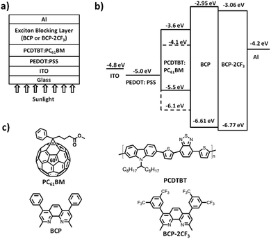 | ||
| Fig. 2 PCDTBT:PC61BM BHJ solar cells with BCP or BCP-2CF3 as an EBL: (a) device structure, (b) energy level diagram and (c) molecular structures. | ||
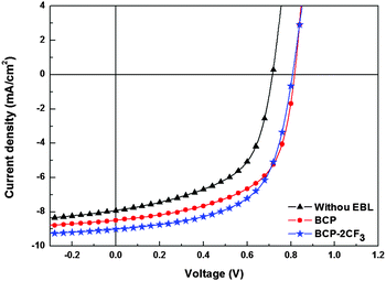 | ||
| Fig. 3 Current density versus voltage (J–V) characteristics of solar cells with and without an EBL under 100 mW cm−2 AM 1.5 G illumination. | ||
BCP and BCP-2CF3 are well comparable in regard to the PCE enhancement. In the presence of an EBL, OPVs demonstrate substantial improvement in open-circuit voltage (VOC), short-circuit current (JSC), and fill factor (FF), which are the concerted effects of two factors. One is the decreased contact resistance between the photoactive layer and the metal cathode, while the other is the suppressed quenching of excitons and holes. It should be noted that the enhancement degrees of the device parameters JSC, FF and VOC are in a similar range of ca. 10%. The VOC is at the same level for all devices with an EBL (ca. 0.83 V) and comparable to the values found for other PCDTBT:PC61BM OPV devices with TiOX as a cathode buffer layer.61 This is in line with the previous studies showing that VOC can be essentially estimated by the energy offset between the acceptor LUMO and the donor HOMO62 under the premise of ohmic contact formation in organic/electrode contacts.
2.4 Device stability and degradation
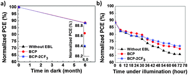
In addition to PCE, stability or lifetime is another key parameter for a solar cell device. A deep understanding of the degradation mechanism is helpful to extend the lifetime of OPV devices. The most conventional way to assess the stability of OPVs is performed by studying the decrease of PCE as a function of degradation time under solar irradiation. As polymer solar cells become more and more stable, it may be time-consuming to monitor the decay process of OPV devices during the whole lifetime under normal working conditions. An accepted method applied is to accelerate the degradation by increasing the temperature or another parameter that influences the lifetime. In this study, the degradation behavior of devices with and without an EBL was investigated under various conditions: in the dark at room temperature (RT), under illumination and thermal annealing. Note that all stability tests were conducted in a nitrogen-filled glove-box (O2 ≤ 0.5 ppm, H2O ≤ 0.1 ppm). In other words, the devices stored inside the glove-box can be regarded as well encapsulated.The study of stability in the dark and under illumination was conducted by employing the same batch of solar cell devices. About 12% losses of their original efficiencies were determined after 6 months in the dark as shown in Fig. 4a. Organic solar cells decay even if kept away from oxygen, light and heat.63,64 The degradation of encapsulated PCDTBT:PC61BM cells was also reported earlier by Heeger65 (with a drop in PCE from 6.1% to 5.8% after 35 days). After 72 hours under illumination (80 mW cm−2 AM 1.5G), OPVs suffered from further deterioration of performance. Devices with an EBL retained about 70% of the initial PCEs, which was slightly higher than that of the reference cell without an EBL (Fig. 4b and Table 3). One reason for the degradation in the dark and under illumination can be attributed to the morphology change of the nanoscale donor–acceptor (D–A) interpenetrating network. It was found that the PCBM gradually aggregates and grows larger over time especially at elevated temperature.66
Thermal annealing was conducted to accelerate the aging rate of OPVs. The devices were heated from RT to gradually increasing temperatures of 80 °C, 100 °C and 120 °C. The annealing duration was 30 min for each temperature. The device performance was recorded and is displayed in Fig. 5. The control device experienced slight and continuous degradation, which is in line with the degradation found in the literature.65 About 7% decrease in PCE was detected after annealing at 120 °C. On the other hand, devices containing an EBL demonstrated dramatic losses of the initial PCEs at different temperatures: 94% for BCP at 100 °C, and 37% for BCP-2CF3 at 120 °C. In comparison with the reference cell, the striking variations should stem from the EBLs. To develop a deeper understanding of the degradation mechanism of OPVs with a BCP-based EBL, the morphology changes of both the PCDTBT:PC61BM BHJ film and the EBLs during thermal treatment will be investigated in the following section.
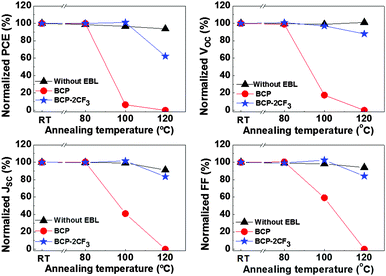 | ||
| Fig. 5 Performance of solar cells with and without an EBL after thermal annealing at different temperatures: variations of PCE, VOC, JSC and FF. | ||
The preparation of the BHJ film for the morphology study was identical to the one applied for the OPV fabrication except using the metal electrode. “Semi-finished solar cells” without the Al cathode (ITO/PEDOT:PSS/BHJ) were fabricated. After annealing in a nitrogen atmosphere, the surface structure of the BHJ film was studied by atomic force microscopy (AFM) in air. The AFM images with a scanning area of 5 × 5 μm2 as well as the root-mean-square (rms) roughness data are displayed in Fig. S2 (ESI†). At RT the BHJ film featured a homogeneous distribution of the donor and acceptor components, with an rms of 0.457 nm. By thermal treatment, the BHJ morphology was not greatly changed, which explained the slight variation in the PCE of the reference cell without an EBL.
As for EBL films, the AFM measurement procedure was the same except for the film preparation. The films were prepared in two different ways. The first procedure adopted the “Semi-finished solar cells” concept just mentioned above to fabricate ITO/PEDOT:PSS/BHJ/EBL (BHJ/EBL for short), from which the evolution of an EBL in a solar cell structure would be observed. In the second protocol EBL compounds were sublimed directly on Si wafers (Si/EBL) to focus on the individual EBL layer.
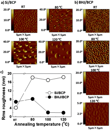
The AFM phase images of BCP are shown in Fig. 6, while the height images with roughness analysis are presented in Fig. S3 (ESI†). BCP revealed a propensity to aggregation. At room temperature, a BCP thin film on a Si substrate was not homogeneous but like a net with some small dents featuring an rms of 4.2 nm. After heating at 80 °C for 30 min, protruding islands of BCP aggregates were formed, which brought a distinct increase in rms to 18.2 nm. When annealed at higher temperatures no big differences were observed.
Without annealing, a BHJ/BCP film showed an rms of 7.0 nm, which was mainly contributed by the BCP layer, since the BHJ sublayer was homogeneous (Fig. S2, ESI†). At 80 °C the crystallization of BCP slightly enhanced the rms from 7.0 nm to 8.3 nm, which might explain the almost unchanged solar cell performance. The same trend was found for the surface roughness of BCP EBL.43 At 100 °C, the BCP layer was expected to undergo vital changes judging from the noticeable device degradation. As a matter of fact, the BCP aggregates seemed to disappear and were difficult to be distinguished by blurred contour profiles and finally led to a 75% reduction in rms. This suggested a gradual “embedding” of the BCP aggregates into the lower heterojunction layer. When the temperature was increased to 120 °C, BCP domains further “embedded” and vanished from the surface. The “embedding” or diffusion of EBL into the BHJ active layer would bring three main disadvantages as follows. Firstly, the surface contact of EBL/Al might be deteriorated, leading to some damage to the ohmic contact at the interface. Secondly, the bicontinuous D–A interpenetrating network might be broken, unfavorable for charge carrier transport. Finally, the anode ITO and the cathode Al might be short-circuited, turning the OPV device into a resistance. These disadvantages were translated into the deteriorations in VOC, JSC, FF and ultimately device efficiency (see Fig. S5, ESI†).
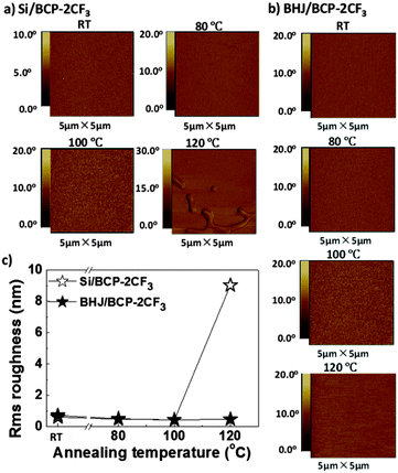
From Fig. 7 and Fig. S4 (ESI†), it can be seen that the evolution process of BCP-2CF3 was different from that of BCP. The film on Si was homogeneous even at 100 °C. This marked difference in appearance could be explained by the molecular structure. Two perfluoromethyl groups on the same phenyl ring of BCP-2CF3 introduced steric hindrance to intermolecular stacking and thus led to aggregates of smaller size and smoother film morphology. When heated up to 120 °C BCP-2CF3 aggregated. However, the aggregation of BCP-2CF3 was not observed in the case of the BHJ/BCP-2CF3 device structure. This might be due to the concurrence of aggregation and the “embedding” processes. As a result, the degradation of the OPV device with BCP-2CF3 at 120 °C could be understood despite no apparent change in the EBL morphology.
Based on the AFM results, it is obvious that BCP-2CF3 demonstrated better durability to heat than BCP. For further confirmation, the thermal properties of BCP and BCP-2CF3 were investigated by differential scanning calorimetry (DSC). BCP possesses a glass transition point (Tg) of 89 °C, lower than that of BCP-2CF3 (153 °C, Fig. S6, ESI†), which is in accordance with the phenomena observed in AFM analysis.
By comparing BCP and BCP-2CF3, it can be found that the incorporation of trifluoromethyl functional groups resulted in a higher Tg and hence a more stable amorphous phase, which are two important factors contributing to the extended lifetime performance of BCP-2CF3 based OPVs during annealing at temperatures higher than 80 °C. The improved thermal stability of BCP-2CF3 makes it promising to survive under severe operation conditions in real-life application.
3. Conclusions
In summary, a new BCP derivative, BCP-2CF3, was synthesized and characterized. The suitability of BCP and BCP-2CF3 as EBL materials was investigated based on PCDTBT:PC61BM solar cells. BCP-2CF3 enhanced the solar cell efficiency by 39%, followed by BCP (30%), as compared to the reference cell without an EBL. Solar cells with an EBL demonstrated comparable stability to the control device under heat treatments below 80 °C if well encapsulated. However, when annealed at a higher temperature of 100 °C, OPVs containing BCP degraded while those with BCP-2CF3 survived intact. During annealing, the aggregation of EBLs and the diffusion of EBL materials into a donor:acceptor BHJ layer were believed to be the main reasons for degradation. In comparison with BCP, BCP-2CF3 with a higher Tg, and better morphological stability is a more competent EBL candidate.4. Experimental
4.1 Ultraviolet-visible absorption (UV-Vis)
UV-Vis spectra were measured on a UV-Vis spectrophotometer (Perkin Elmer Lambda 900). The concentration of solutions was 10−6 M in dichloromethane (DCM).4.2 Cyclic voltammetry (CV)
The CV measurement was performed on an EG&G Princeton Applied Research potentiostat, model 273. The working electrode consisted of an inlaid platinum disk (1.5 mm diameter) that was polished on a felt pad with 0.05 μm alumina and sonicated in milli-Q water for 5 min before each measurement. A platinum wire was used as the counter electrode and an Ag wire was used as the reference electrode internally calibrated with ferrocene/ferrocenium (Fc/Fc+). The three electrodes were dipped into a mixed solution of tetrabutylammonium hexafluorophosphate (Bu4NPF6, 0.1 M) and the compound to be measured (0.001 M) in dry DCM. The CV measurements were carried out with a scan rate of 50 mV s−1 at room temperature under argon.4.3 Device fabrication and characterization
In this study, BHJ solar cells were fabricated on indium tin oxide (ITO) coated glass substrates with a sheet resistance of ca. 20 Ω □−1 (Kintec Company). The substrates were first cleaned with isopropanol in an ultrasonic bath for 10 min; the procedure was repeated 3 times, followed by oxygen plasma cleaning for 10 min. A layer of poly(3,4-ethylenedioxythiophene):poly(styrenesulfonate) (PEDOT:PSS, Aldrich) was spin-cast at 5000 rpm for 60 s. After that, the substrate was heated at 140 °C for 10 min in air and then was moved into a nitrogen glove-box. A mixture of PCDTBT (1 Material) and PC61BM (American Dye Source, Inc.) was spin-coated onto the PEDOT:PSS layer at a speed of 1300 rpm for 120 s. The blended solution was prepared with PCDTBT![[thin space (1/6-em)]](https://www.rsc.org/images/entities/char_2009.gif) :
:![[thin space (1/6-em)]](https://www.rsc.org/images/entities/char_2009.gif) PC61BM (6
PC61BM (6![[thin space (1/6-em)]](https://www.rsc.org/images/entities/char_2009.gif) :
:![[thin space (1/6-em)]](https://www.rsc.org/images/entities/char_2009.gif) 24 mg) dissolved in 1 ml of a mixture of chlorobenzene
24 mg) dissolved in 1 ml of a mixture of chlorobenzene![[thin space (1/6-em)]](https://www.rsc.org/images/entities/char_2009.gif) :
:![[thin space (1/6-em)]](https://www.rsc.org/images/entities/char_2009.gif) 1,2-dichlorobenzene (0.25
1,2-dichlorobenzene (0.25![[thin space (1/6-em)]](https://www.rsc.org/images/entities/char_2009.gif) :
:![[thin space (1/6-em)]](https://www.rsc.org/images/entities/char_2009.gif) 0.75 ml) and stirred on a heating plate at 80 °C for overnight. After spin-coating of the active layer, the substrates were left inside the glove-box for 8–12 hours. A 5 nm-thick EBL (BCP or BCP-2CF3) was deposited on top of the active layer through a mask by thermal sublimation (0.1–0.2 nm s−1 at a pressure lower than 5 × 10⁻⁶ mbar). Finally, a 100 nm Al cathode was evaporated as the cathode (0.1 nm s−1 at a pressure lower than 5 × 10⁻⁶ mbar). The current density–voltage (J–V) characteristics of the devices were recorded in an ambient atmosphere of nitrogen under 100 mW cm−2 AM 1.5 G solar illumination (Lichttechnik, Germany).
0.75 ml) and stirred on a heating plate at 80 °C for overnight. After spin-coating of the active layer, the substrates were left inside the glove-box for 8–12 hours. A 5 nm-thick EBL (BCP or BCP-2CF3) was deposited on top of the active layer through a mask by thermal sublimation (0.1–0.2 nm s−1 at a pressure lower than 5 × 10⁻⁶ mbar). Finally, a 100 nm Al cathode was evaporated as the cathode (0.1 nm s−1 at a pressure lower than 5 × 10⁻⁶ mbar). The current density–voltage (J–V) characteristics of the devices were recorded in an ambient atmosphere of nitrogen under 100 mW cm−2 AM 1.5 G solar illumination (Lichttechnik, Germany).
4.4 Atomic force microscopy (AFM)
AFM was performed using a Veeco Multimode (Dimension 3100). The cantilever was produced by Olympus, with type number OMCLAC 160 TS-W2 silicon.4.5 Differential scanning calorimetry (DSC)
DSC measurement was performed on a Mettler DSC 30 at a heating/cooling rate of 10 °C min−1 in nitrogen.Acknowledgements
We gratefully acknowledge the financial support from the Bundesministerium für Bildung und Forschung (BMBF) and BASF SE.Notes and references
- Z. He, B. Xiao, F. Liu, H. Wu, Y. Yang, S. Xiao, C. Wang, T. Russell and Y. Cao, Nat. Photonics, 2015, 9, 174 CrossRef CAS
.
- M. Green, K. Emery, Y. Hishikawa, W. Warta and E. Dunlop, Prog. Photovolt: Res. Appl., 2015, 23, 805 CrossRef
.
- H. Hoppe and N. Sariciftci, J. Mater. Res., 2004, 19, 1924 CrossRef CAS
.
- G. Li, R. Zhu and Y. Yang, Nat. Photonics, 2012, 6, 153 CrossRef CAS
.
- L. Dou, J. You, Z. Hong, Z. Xu, G. Li, R. Street and Y. Yang, Adv. Mater., 2013, 25, 6642 CrossRef CAS PubMed
.
- X. Zhan, Z. Tan, B. Domercq, Z. An, X. Zhang, S. Barlow, Y. Li, D. Zhu, B. Kippelen and S. Marder, J. Am. Chem. Soc., 2007, 129, 7246 CrossRef CAS PubMed
.
- Y. Cheng, S. Yang and C. Hsu, Chem. Rev., 2009, 109, 5868 CrossRef CAS PubMed
.
- Z. Zhang and J. Wang, J. Mater. Chem., 2012, 22, 4178 RSC
.
- X. Guo, M. Baumgarten and K. Müllen, Prog. Polym. Sci., 2013, 38, 1832 CrossRef CAS
.
- Y. Lin, Y. Wang, J. Wang, J. Hou, Y. Li, D. Zhu and X. Zhan, Adv. Mater., 2014, 26, 5137 CrossRef CAS PubMed
.
- Y. Lin, J. Wang, Z. Zhang, H. Bai, Y. Li, D. Zhu and X. Zhan, Adv. Mater., 2015, 27, 1170 CrossRef CAS PubMed
.
- H. Meier, Angew. Chem., Int. Ed., 2005, 44, 2482 CrossRef CAS PubMed
.
- L. Bu, X. Guo, B. Yu, Y. Qu, Z. Xie, D. Yan, Y. Geng and F. Wang, J. Am. Chem. Soc., 2009, 131, 13242 CrossRef CAS PubMed
.
- L. Bu, X. Guo, B. Yu, Y. Fu, Y. Qu, Z. Xie, D. Yan, Y. Geng and F. Wang, Polymer, 2011, 52, 4253 CrossRef CAS
.
- J. Qu, B. Gao, H. Tian, X. Zhang, Y. Wang, Z. Xie, H. Wang, Y. Geng and F. Wang, J. Mater. Chem. A, 2014, 2, 3632 CAS
.
- D. Mühlbacher, M. Scharber, M. Morana, Z. Zhu, D. Waller, R. Gaudiana and C. Brabec, Adv. Mater., 2006, 18, 2884 CrossRef
.
- N. Blouin, A. Michaud and M. Leclerc, Adv. Mater., 2007, 19, 2295 CrossRef CAS
.
- Y. Liang, Z. Xu, J. Xia, S. Tsai, Y. Wu, G. Li, C. Ray and L. Yu, Adv. Mater., 2010, 22, E135 CrossRef CAS PubMed
.
- M. Wang, X. Hu, P. Liu, W. Li, X. Gong, F. Huang and Y. Cao, J. Am. Chem. Soc., 2011, 133, 9638 CrossRef CAS PubMed
.
- J. Bredas, D. Beljonne, V. Coropceanu and J. Cornil, Chem. Rev., 2004, 104, 4971 CrossRef CAS PubMed
.
- B. Thompson and J. Fréchet, Angew. Chem., Int. Ed., 2008, 47, 58 CrossRef CAS PubMed
.
- Y. Liang, D. Feng, Y. Wu, S. Tsai, G. Li, C. Ray and L. Yu, J. Am. Chem. Soc., 2009, 131, 7792 CrossRef CAS PubMed
.
- H. Chen, J. Hou, S. Zhang, Y. Liang, G. Yang, Y. Yang, L. Yu, Y. Wu and G. Li, Nat. Photonics, 2009, 3, 649 CrossRef CAS
.
- L. Hou, J. Hou, S. Zhang, H. Chen and Y. Yang, Angew. Chem., Int. Ed., 2010, 49, 1500 CrossRef PubMed
.
- S. Dimitrov, A. Bakulin, C. Nielsen, B. Schroeder, J. Du, H. Bronstein, I. McCulloch, R. Friendand and J. Durrant, J. Am. Chem. Soc., 2012, 134, 18189 CrossRef CAS PubMed
.
- A. Salleo, R. Kline, D. DeLongchamp and M. Chabinys, Adv. Mater., 2010, 22, 3812 CrossRef CAS PubMed
.
- S. Massip, P. Oberhumer, G. Tu, S. Albert-Seifried, W. Huck, R. Friend and N. Greenham, J. Phys. Chem. C, 2011, 115, 25046 CAS
.
- A. Yiu, P. Beaujuge, O. Lee, C. Woo, M. Toney and J. Fréchet, J. Am. Chem. Soc., 2012, 134, 2180 CrossRef CAS PubMed
.
- R. Fitzner, E. Mena-Osteritz, A. Mishra, G. Schulz, E. Reinold, M. Weil, C. Körner, H. Ziehlke, C. Elschner, K. Leo, M. Riede, M. Pferffer, C. Uhrich and P. Bäuerle, J. Am. Chem. Soc., 2012, 134, 11064 CrossRef CAS PubMed
.
- K. Johnson, Y. Huang, S. Huettner, M. Sommer, M. Brinkmann, R. Mulherin, D. Niedzialek, D. Beljonne, J. Clark, W. Huck and H. Friend, J. Am. Chem. Soc., 2013, 135, 5074 CrossRef CAS PubMed
.
- V. Gevaerts, E. Herzig, M. Kirkus, K. Hendriks, M. Wienk, J. Perlich, P. Müller-Buschbaum and R. Jassen, Chem. Mater., 2014, 26, 916 CrossRef CAS
.
- H. Ma, H. Yip, F. Huang and A. Jen, Adv. Funct. Mater., 2010, 20, 1371 CrossRef CAS
.
- R. Steim, F. Kogler and C. Brabec, J. Mater. Chem., 2010, 20, 2499 RSC
.
- R. Po, C. Carbonera, A. Bernardi and N. Camaioni, Energy Environ. Sci., 2011, 4, 285 CAS
.
-
C. Duan, C. Zhong, F. Huang and Y. Cao, in Organic Solar Cells Materials and Device Physics, ed. W. C. H. Choy, Springer, London, vol. 3, 2013, p. 431 Search PubMed
.
- P. Peumans, A. Yakimov and S. Forrest, Appl. Phys. Rev., 2003, 93, 3693 CrossRef CAS
.
- L. Motiei, Y. Yao, J. Choudhury, H. Yan, T. Marks, M. Boom and A. Facchetti, J. Am. Chem. Soc., 2010, 132, 12528 CrossRef CAS PubMed
.
- P. Peumans, V. Bulović and S. Forrest, Appl. Phys. Lett., 2000, 76, 2650 CrossRef CAS
.
- M. Chan, C. Lee, S. Lai, M. Fung, F. Wong, H. Sun, K. Lau and S. Lee, J. Appl. Phys., 2006, 100, 094506 CrossRef
.
- H. Wu, Q. Song, M. Wang, F. Li, H. Yang, Y. Wu, C. Huang, X. Ding and X. Hou, Thin Solid Films, 2007, 515, 8050 CrossRef CAS
.
- N. Wang, J. Yu, J. Huang and Y. Jiang, Sol. Energy Mater. Sol. Cells, 2010, 94, 263 CrossRef CAS
.
- Q. Song, F. Li, H. Yang, H. Wu, X. Wang, W. Zhou, J. Zhao, X. Ding, C. Huang and X. Hou, Chem. Phys. Lett., 2005, 416, 42 CrossRef CAS
.
- S. Liu, C. Lee, C. Lin, J. Huang, C. Chen and J. Lee, J. Mater. Chem., 2010, 20, 7800 RSC
.
- J. Lee, S. Cho, A. Roy, H. Jung and A. Heeger, Appl. Phys. Lett., 2010, 96, 163303 CrossRef
.
- P. Peumans and S. Forrest, Appl. Phys. Lett., 2001, 79, 126 CrossRef CAS
.
- A. Hayakawa, O. Yoshikawa, T. Fujieda, K. Uehara and S. Yoshikawa, Appl. Phys. Lett., 2007, 90, 163517 CrossRef
.
- S. Lee, D. Kim, J. Kim, G. Lee and J. Park, J. Phys. Chem. C, 2009, 113, 21915 CAS
.
- C. Chang, C. Lin, J. Chiou, T. Ho, Y. Tai, J. Lee, Y. Chen, J. Wang, L. Chen and K. Chen, Appl. Phys. Lett., 2010, 96, 263506 CrossRef
.
- C. Li, M. Schwab, Y. Zhao, L. Chen, I. Bruder, I. Münster, P. Erk and K. Müllen, Dyes Pigm., 2013, 97, 258 CrossRef CAS
.
- Y. Zhao, L. Chen, C. Li and K. Müllen, Synth. Met., 2013, 174, 46 CrossRef CAS
.
- S. Heutz, P. Sullivan, B. Sanderson, S. Schultes and T. Jones, Sol. Energy Mater. Sol. Cells, 2004, 83, 229 CrossRef CAS
.
- Z. Hong, Z. Huang and X. Zeng, Chem. Phys. Lett., 2006, 425, 62 CrossRef CAS
.
- Z. Hong, Z. Huang and X. Zeng, Thin Solid Films, 2007, 515, 3019 CrossRef CAS
.
- M. Hermenau, M. Riede, K. Leo, S. Gevorgyan, F. Krebs and K. Norrman, Sol. Energy Mater. Sol. Cells, 2011, 95, 1268 CrossRef CAS
.
- M. Hermenau, S. Schulbert, H. Klumbies, J. Fahlteich, L. Müller-Meskamp, K. Leo and M. Riede, Sol. Energy Mater. Sol. Cells, 2012, 97, 102 CrossRef CAS
.
- M. Schmittel and H. Ammon, Eur. J. Org. Chem., 1998, 785 CrossRef CAS
.
- M. Henry and M. Hoffman, J. Phys. Chem., 1979, 83, 618 CrossRef CAS
.
- G. Parthasarathy, P. Burrows, V. Khalfin, V. Kozlov and S. Forrest, Appl. Phys. Lett., 1998, 72, 2138 CrossRef CAS
.
-
C. Shen, A. Kahn and I. Hill, in Conjugated Polymer and Molecular Interfaces, ed. W. Salaneck, K. Seki, A. Kahn and J.
Pireaux, MarcelDekker, Inc., New York, 2001, vol. 11, p. 351 Search PubMed
.
- A. Kahn, N. Koch and W. Gao, J. Polym. Sci., Part B: Polym. Phys., 2003, 41, 2529 CrossRef CAS
.
- S. Cowan, W. Leong, N. Banerji, G. Dennler and A. Heeger, Adv. Funct. Mater., 2011, 21, 3083 CrossRef CAS
.
- M. Scharber, D. Mühlbacher, M. Koppe, P. Denk, C. Waldauf, A. Heeger and C. Brabec, Adv. Mater., 2006, 18, 789 CrossRef CAS
.
- M. Jørgensen, K. Norrman and F. Krebs, Sol. Energy Mater. Sol. Cells, 2008, 92, 686 CrossRef
.
- J. Lee, J. Jung, J. Jo and W. Jo, J. Mater. Chem., 2012, 22, 24265 RSC
.
- S. Park, A. Roy, S. Beaupré, S. Cho, N. Coates, J. Moon, D. Moses, M. Leclerc, K. Lee and A. Heeger, Nat. Photonics, 2009, 3, 297 CrossRef CAS
.
- X. Yang, J. Duren, R. Janssen, M. Michels and J. Loos, Macromolecules, 2004, 37, 2151 CrossRef CAS
.
Footnote |
| † Electronic supplementary information (ESI) available: Cyclic voltammetry results; current density–voltage characteristics of the OPVs after thermal annealing; morphology evolutions of the PCDTBT:PC61BM BHJ film and EBL films during thermal annealing. See DOI: 10.1039/c6tc00780e |
| This journal is © The Royal Society of Chemistry 2016 |

