
 Open Access Article
 This Open Access Article is licensed under a
 Creative Commons Attribution 3.0 Unported Licence
An efficient PE-ALD process for TiO2 thin films employing a new Ti-precursor†
M.
Gebhard
a,
F.
Mitschker
b,
M.
Wiesing
c,
I.
Giner
c,
B.
Torun
c,
T.
de los Arcos
c,
P.
Awakowicz
b,
G.
Grundmeier
c and
A.
Devi
*a
aInorganic Materials Chemistry, Ruhr-University Bochum, 44780 Bochum, Germany. E-mail: anjana.devi@rub.de
bInstitute of Electrical Engineering and Plasma Technology, Ruhr-University Bochum, 44780 Bochum, Germany
cMacromolecular and Technical Chemistry, University of Paderborn, 33098 Paderborn, Germany
First published on 11th January 2016
Abstract
An efficient plasma-enhanced atomic layer deposition (PE-ALD) process was developed for TiO2 thin films of high quality, using a new Ti-precursor, namely tris(dimethylamido)-(dimethylamino-2-propanolato)titanium(IV) (TDMADT). The five-coordinated titanium complex is volatile, thermally stable and reactive, making it a potential precursor for ALD and PE-ALD processes. Process optimization was performed with respect to plasma pulse length and reactive gas flow rate. Besides an ALD window, the application of the new compound was investigated using in situ quartz-crystal microbalance (QCM) to monitor surface saturation and growth per cycle (GPC). The new PE-ALD process is demonstrated to be an efficient procedure to deposit stoichiometric titanium dioxide thin films under optimized process conditions with deposition temperatures as low as 60 °C. Thin films deposited on Si(100) and polyethylene-terephthalate (PET) exhibit a low RMS roughness of about 0.22 nm. In addition, proof-of-principle studies on TiO2 thin films deposited on PET show promising results in terms of barrier performance with oxygen transmission rates (OTR) found to be as low as 0.12 cm3 × cm−2 × day−1 for 14 nm thin films.
Introduction
Titanium dioxide (TiO2) represents a highly versatile material with applications ranging from self-cleaning and anti-reflecting coatings, photocatalysis (water splitting), transparent conductive oxides and semiconductors.1–4 More recently, the application of TiO2 thin films as gas barrier coating has attracted a lot of interest.5–7 Similar to SiOx and Al2O3, the amorphous structure of a densely packed inorganic thin film of TiO2 shows promising barrier performance toward imperiling gases and vapors, such as oxygen and water.8,9 The deposition of defect-free thin films is of particular high importance for application as gas barrier coating, as it is known that nano- and micro-defects play a significant role in the diffusion of gases and vapors through barrier layers.10–13 In this context, ALD is one of the promising deposition techniques with distinct advantages over other thin film coating methods. Due to the self-limiting growth, highly conformal thin films can be obtained even over large areas or complex surface geometries.14 In particular, ALD enables a pinhole free and uniform coating of structures even with high aspect ratios.15 In addition, low temperature processes decrease the mechanical stress between an inorganic thin film and a polymer substrate, which is often caused by different thermal expansion coefficients.16 The coating of established and emerging high-tech components in state-of-the-art technologies, such as solar-cells and flexible electronics, is especially challenging in terms of sensitive substrate arrangements like integrated circuits or organic light emitting diodes (OLEDs).9,17 In particular, the coating of polymers makes processes operating at low temperatures a necessity.18 A good option can be found in PE-ALD, where heat treatment of substrates can be decreased near to room temperature, thus meeting the aforementioned requirements without destroying the substrates.19,20 In addition, impinging and highly reactive plasma species cause higher degrees of cross-linking within the growing thin film, making it more compact and denser.21,22 Thin films of TiO2 have been deposited by ALD using various precursors such as TiCl4, [Ti(iOPr)4] (TTIP) and [Ti(NMe2)4] (TDMAT).23–25 Additionally, heteroleptic compounds like amino-alkoxides ([Ti(NMe2)2(dmae)2]), mixed alkoxide-cyclopentadienyls ([Cp*Ti(OMe)3]) and alkoxide-amidinates ([Ti(OiPr)3(NiPr-Me-amd)]) of titanium were successfully applied in ALD to grow TiO2 thin films.26–29 Several processes to deposit TiO2 by thermal ALD have been described in the literature, including detailed investigations on the mechanisms and thin film characteristics.29,30 Detailed investigations on PE-ALD processes to deposit titanium dioxide, including spatial ALD at low temperatures (<100 °C), cover the already mentioned precursors TiCl4, TTIP and TDMAT.7,26,31–35 In addition, other heteroleptic complexes with bulky chelating groups, namely [Ti(NMe2)2(dmap)2] and [Ti(NMe2)3(guan)], were developed and [Ti(NMe2)3(guan)] was successfully applied to grow high-κ TiO2 thin films using PE-ALD.36,37 As TDMAT shows limited thermal stability, the partial modification with alkyl-amido ligands is an option to develop precursors with enhanced thermal stability without compromising on the high volatility and reactivity of the parent TDMAT. Herein, we present an efficient PE-ALD process to deposit TiO2 thin films at low temperatures, based on a new five-coordinated Ti-complex, namely tris(dimethylamido)(dimethylamino-2-propanolato)titanium(IV) ([Ti(NMe2)3(dmap)], TDMADT (2), Scheme 1) and its characterization.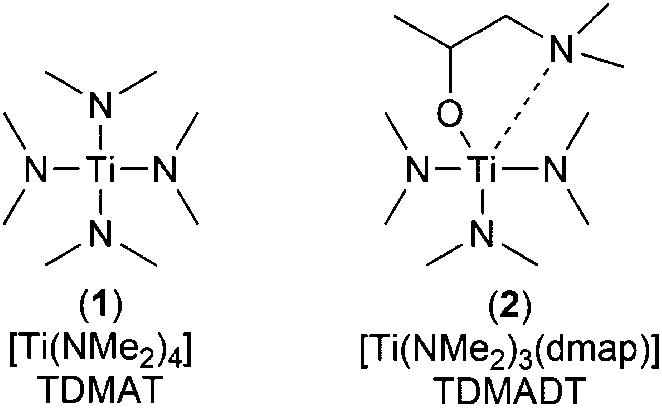 | ||
| Scheme 1 Schematic structure of the conventional Ti-precursor TDMAT (1) and its new derivative TDMADT (2). | ||
Owing to the promising physico-chemical characteristics in terms of volatility, reactivity and thermal stability, the new Ti-compound was employed to deposit TiO2via PE-ALD both on silicon and on PET substrates to investigate the growth characteristics and to fabricate gas barrier coatings (GBC). The results are compared to TiO2 thin films deposited by PE-ALD using the parent TDMAT precursor.
Experimental section
Precursor synthesis and characterization
Characterization
NMR spectra were recorded on a Bruker Avance DPX 200. All spectra were referenced to an internal standard (TMS, δ = 0.00 ppm), while dried deuterated benzene was the solvent in all cases (solvent reference peak is δ = 7.16 ppm). For temperature-dependent NMR studies, deuterated toluene was chosen due to its higher boiling point. Stacked spectra have been normalized to the largest peak. Thermogravimetric analysis (TGA) was carried out on a Seiko TG/DTA 6200/SII device, applying a heating rate of 5 K min−1 under N2 flow (300 ml min−1). For each measurement, a sample mass of about 15 mg was weighed in an aluminum crucible. Elemental analysis was carried out at Microlab Kolbe in Mülheim, Germany. For CHN determination, a Vario EL analyzer from Elementar was used while titanium was measured using a Specord 50 device from AnalytikJena.Thin film deposition
All depositions were carried out in a custom built stainless steel showerhead reactor, operating an ECWR plasma at 13.56 MHz.37 The precursors were filled in stainless steel cartridges maintained at 70 °C and 90 °C for TDMAT (1) and TDMADT (2), respectively. Precursors were pulsed without additional carrier gas. For all depositions, RF power was set to 200 W while the reflected power was 50–55 W. Oxygen (AirLiquide, 99.995%) and argon (AirLiquide, 99.999%) gas flow was monitored during the respective pulse times by mass flow meters. A fixed flow rate of 15 sccm was set for Ar. After evacuation, a base pressure of 5 × 10⁻⁴ mbar was reached. For optimizing the ALD process, depositions were performed on polished 2-inch p-type Si(100) wafers. Before each deposition, the substrates were cleaned as follows: After rinsing in boiling isopropanol, acetone and again isopropanol, the substrates were ultrasonicated in HPLC grade water for 10 minutes. PET substrates (Hostaphan RD 23, Mitsubishi Polyester Films, Wiesbaden, Germany, 23 μm thick) were used as received. The temperature of the substrate holder was set to 60 °C for all depositions. Investigations on the ALD window, saturation behavior and linearity were carried out by applying the following optimized deposition sequence: The Ti-precursor was pulsed two times for 40 ms each, separated by an intermediate 200 ms gap. After 500 ms, a two-step purge, each of 50 ms separated by a 100 ms pumping step, took place. After 850 ms, oxygen gas was introduced into the system and the plasma was ignited after 150 ms. The oxygen pulse was also used as the second purging step, lasting in total for 600 ms.Thin film characterization
Thin film thickness on Si(100) was measured using reflectometry on a FilMetrics F20 device, applying literature data for the refractive index and extinction coefficient in the range from 400 nm to 1000 nm. Each sample was measured at five different points on the wafer surface to verify the film thickness uniformity across the substrate. In situ QCM measurements were made using an ALD-sample holder attached to a SO-100 Oscillator (6 MHz) and a SQM-160 thin film deposition monitor (JCM, Inficon). For measurements, AT-cut QCM crystals coated with Au and optimized for deposition at 120 °C were used. Atomic force microscopy (AFM) on selected samples was performed using a JPK Nanowizard III Ultra (JPK Instruments AG) equipped with an anti-noise and anti-vibration box. All images were recorded in air using intermittent contact mode. AFM raw data were processed using the open-source software Gwyddion.39 The composition of thin films deposited on silicon was determined employing Rutherford backscattering spectrometry (RBS) in combination with nuclear reaction analysis (NRA) at RUBION, the Central Unit for Ion Beams and Radionuclides at Ruhr-University Bochum. RBS measurements were made with a 2 MeV He+ beam with a beam intensity of about 60–80 nA and a tilt angle of 7°. The RBS detector, with an energy resolution of 16 keV, was placed at 160° in Cornell geometry and included a 6 μm Ni foil. For NRA, a deuteron beam of 1 MeV was used while samples were tilted by an angle of 22.5° or 7° with respect to the beam. A detector for nuclear reaction products was placed at 135° in IBM geometry. All recorded spectra were analyzed using SIMNRA software.40 XPS was carried out within an ESCA+ facility (Omicron) at a base pressure of <1 × 10⁻¹⁰ mbar using monochromated Al Kα radiation (XM1000, 300 W, 1486.7 eV) and a charge neutralizer (CN 10+, 4.0 eV, 9 μA). Core level spectra were recorded at a constant analyzer energy of 20 eV and at 15° and 60° emission angle relative to the surface normal. The energy calibration was done by shifting the C1s signal of adventitious carbon to 284.8 eV. The measuring depth at the investigated angles is 5.5 nm (15°) and 2.8 nm (60°), respectively. Oxygen transmission rates (OTR) were monitored using a commercial Mocon OX-TRAN 2/61 (Mocon Inc., Minneapolis, USA) using the carrier gas method at 23 °C and 0% humidity.Results and discussion
Precursor evaluation
The new compound TDMADT was evaluated in terms of its chemical and thermal properties in view of its potential application in ALD processes. After isolation of the product, detailed investigations on the thermal properties and decomposition were carried out, employing temperature dependent 1H-NMR spectroscopy, TGA and isothermal TGA. The synthesis route adopted resulted in high yields (>99%) of the target compound and it was found to be spectroscopically pure as verified from NMR analysis. For temperature-dependent 1H-NMR studies, all measurements were carried out using the same sample while the spectra (Fig. 1) were recorded after 10 minutes at the respective temperature.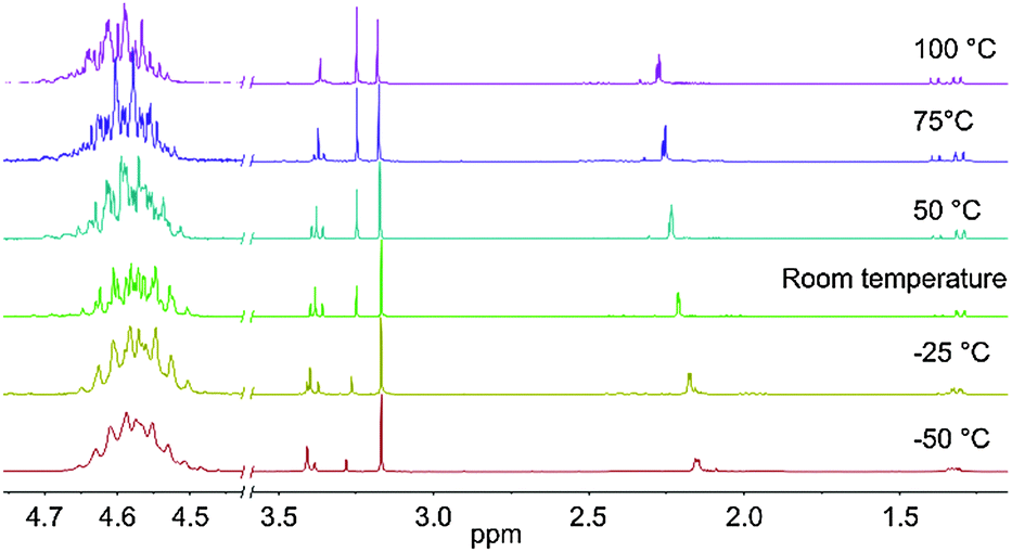 | ||
| Fig. 1 Temperature-dependent 1H-NMR spectra of TDMADT at different temperatures. Left: Cut-out of the selected region between 4.45 ppm and 4.75 ppm showing the complex multiplet. | ||
From these studies it is evident that no decomposition takes place up to 100 °C, as no additional peaks develop and integration of the respective area is constant with changing temperature. The downfield shifted dimethylamido groups at the metal center show a high fluctuation, indicated by the triplet between 3.35 ppm and 3.43 ppm for −50 °C and 100 °C, respectively. At lower temperatures, this triplet becomes less resolved and appears as two broad signals, which might migrate to only one signal at even lower temperatures. The triplet shape vanishes at higher temperatures, showing higher fluctuation of the three amide groups. In addition to the shape of the triplet, the intensity of the two singlets (3.17 ppm and 3.25 ppm) and the triplet changes from a non-equilibrium ratio of 4.5![[thin space (1/6-em)]](https://www.rsc.org/images/entities/char_2009.gif) :1:4.5 at −50 °C to an equal ratio of nearly 1:1:1 at 100 °C. Interestingly, the multiplet at 1.35 ppm, assigned to the carbon-bonded methyl group of the dmap-ligand, shows the tendency to become better resolved at higher temperatures. While the signal appears as a broad multiplet at −50 °C, it can be identified as a doublet of doublets already at −25 °C. With increasing temperature, it develops again into a multiplet with even sharper peaks. This behavior might be caused by the dimer–monomer exchange phenomenon.41 At −50 °C, the methyl groups adjacent to the nitrogen atom in the ligand (2.15 ppm) appear as a roughly resolved doublet at 2.15 ppm, which is shifted downfield at higher temperatures and splits into two singlets at 100 °C. The CH2 group of the ligand is nested around these two singlets, showing manifold coupling both at 1.97 ppm and at 2.37 ppm. The proton located at the oxygen-bonded carbon atom exhibits the highest chemical shift at 4.58 ppm with a complex multiplet (cut-out of the selected region in Fig. 1).
:1:4.5 at −50 °C to an equal ratio of nearly 1:1:1 at 100 °C. Interestingly, the multiplet at 1.35 ppm, assigned to the carbon-bonded methyl group of the dmap-ligand, shows the tendency to become better resolved at higher temperatures. While the signal appears as a broad multiplet at −50 °C, it can be identified as a doublet of doublets already at −25 °C. With increasing temperature, it develops again into a multiplet with even sharper peaks. This behavior might be caused by the dimer–monomer exchange phenomenon.41 At −50 °C, the methyl groups adjacent to the nitrogen atom in the ligand (2.15 ppm) appear as a roughly resolved doublet at 2.15 ppm, which is shifted downfield at higher temperatures and splits into two singlets at 100 °C. The CH2 group of the ligand is nested around these two singlets, showing manifold coupling both at 1.97 ppm and at 2.37 ppm. The proton located at the oxygen-bonded carbon atom exhibits the highest chemical shift at 4.58 ppm with a complex multiplet (cut-out of the selected region in Fig. 1).
The TG analysis of TDMADT revealed single step vaporization and the weight loss characteristics are similar to the parent amide (TDMAT) as shown in Fig. 2, except that the onset temperature for volatilization is shifted to slightly higher temperatures (60 °C). It should be noted that the onset of evaporation as well as the decomposition temperature of 180 °C for the TDMADT (2) follows the trend of the earlier reported compound [Ti(dmap)2(NMe2)2],36 where two dimethylamido ligands have been substituted by dmap-ligands. For this compound, temperatures for onset of evaporation and decomposition were found to be 100 °C and 230 °C, respectively. From TG studies it can be summarized that the substitution of one of the parent amide groups with a chelating dmap ligand resulted in an increased thermal stability, while volatilization temperature was not significantly affected.
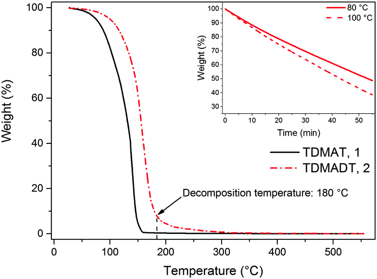 | ||
| Fig. 2 TGA curves of TDMAT and its derivative TDMADT. Inset: Iso-TGA of TDMADT at 80 °C and 100 °C. | ||
The volatility, enhanced thermal stability and reactivity renders the new compound as a promising precursor for ALD application. From isothermal TGA at 80 °C and 100 °C (shown as the inset in Fig. 2) a nearly constant weight loss was observed. This indicates that a constant mass transport of the precursor could be achieved during the ALD process.
Growth characteristics
The PE-ALD process, employing the new Ti-compound as precursor, was investigated in terms of surface saturation, ALD window and linearity. In situ QCM was used to determine surface saturation during precursor feed. Here, changes in the frequency of the oscillating quartz crystal are monitored. According to the Sauerbrey equation, the change of the resonance frequency of the quartz crystal can be correlated to mass adsorbed on the substrate during the deposition process. As we found that the employed QCM crystals exhibit a root-mean-square (RMS) roughness significantly higher than that of the usually used substrates like silicon (1.0 μm vs. 0.22 nm), our results are presented as the shift in the frequency of the QCM. Fig. 3 shows the results from two feeding times, 2 × 40 ms and 2 × 150 ms, for TDMADT and one feeding time (2 × 40 ms) for TDMAT.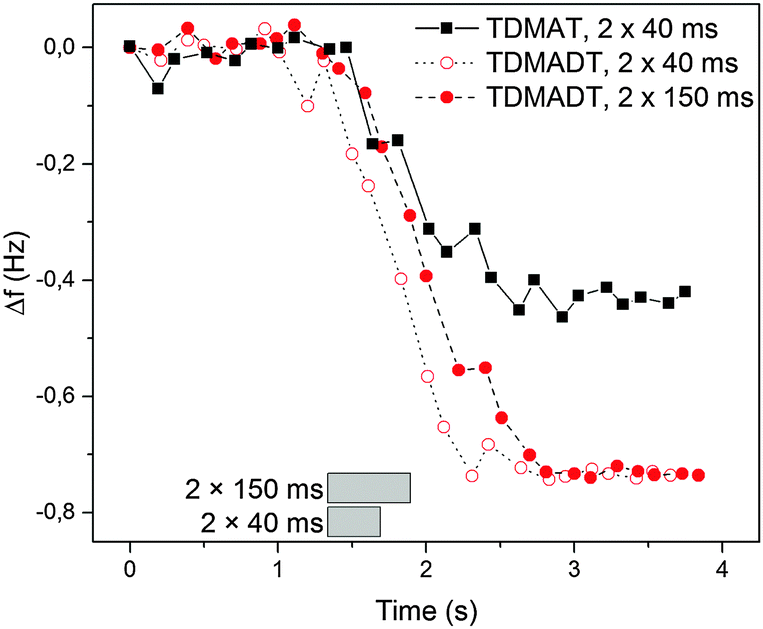 | ||
| Fig. 3 In situ QCM studies at 66 °C on the surface saturation during precursor pulse using TDMADT. Grey blocks show the beginning and ending of the complete precursor pulse time. | ||
In each case, the precursor was pulsed two times interrupted by a 200 ms gap. For the two different feedings of TDMADT, surface saturation was achieved after about 1.0 s, indicated by the emerging plateaus. The adsorption of TDMADT causes a frequency shift of 0.75 Hz, which is about 0.3 Hz higher than for TDMAT. As in both cases surface saturation is achieved, the only explanation for this difference in frequency shift is the different molecular mass of the two precursors. This implies that the heavier dmap-ligand is still bonded to the Ti-atom, most likely facing away from the substrate surface, and surface bonding takes place through the cleavage of a Ti–NMe2 bond. This assumption is confirmed by taking into account the ratio of molecular masses vs. the ratio of frequency shift for the respective precursors. According to ALD mechanisms, TDMAT (1) can be described as Ti(NMe2)2 after adsorption on the quartz surface, while TDMADT (2) can be described as Ti(NMe2)(dmap). In both cases, the coordination sphere of titanium is filled with two additional oxygen atoms from the substrate surface. According to eqn (1), the ratio of M1/M2 should be equal to Δf1/Δf2.
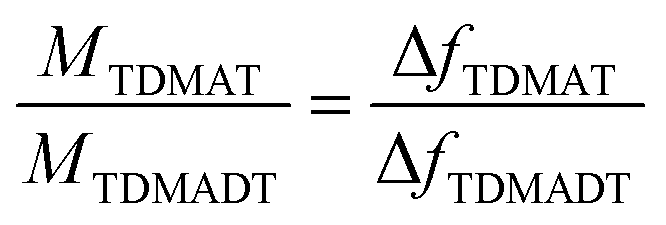 | (1) |
The process was further investigated employing QCM with regard to consistency of repeated cycles. Here, in contrast to saturation studies, a whole and continuous process was investigated. A cut-out from a representative plot of frequency shift vs. time, obtained from a PE-ALD process using TDMADT, is shown in Fig. 4.
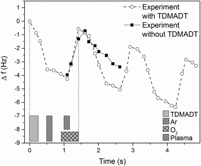 | ||
| Fig. 4 Circles: QCM response over time during PE-ALD of TiO2 using TDMADT and oxygen plasma at 66 °C. The precursor pulse time was 2 × 40 ms, according to QCM results from saturation studies. Squares: QCM response from a blind experiment without precursor supply. The blocks beneath the graph indicate the start, length and end of the respective pulses. | ||
From blind experiments (same process without precursor supply) the QCM response was monitored to allow a reasonable interpretation of the obtained data (black squares). During these blind experiments, the plasma pulse is accompanied by a positive frequency shift of 3.25 Hz. When the plasma is turned off, it is expected that the crystal equilibrates to its earlier frequency. Here, a difference of 0.58 Hz remains, indicating that the crystal needs more time for sufficient equilibration. As there was no additional pumping step between plasma-off and the next precursor supply, i.e. between two cycles, it has to be taken into account that this negative frequency shift is always superimposed by the event of precursor adsorption, which is expected to be 0.73 Hz from saturation studies.
Therefore, the negative frequency shift during the precursor pulse should be 3.98 Hz. Indeed, we found a frequency shift for this event of 4.48 Hz. As known from blind experiments, the difference of about 0.5 Hz is most likely caused by a thermal non-equilibrium of the crystal. The results from QCM analysis are encouraging, as the ALD criteria of surface saturation and linear increase in thickness are proven preliminary to detailed studies on comprehensive deposition series. In addition, it is most likely that the dmap-ligand of the new compound is still intact and can act partially as an oxygen source. As mentioned above, the difference in RMS roughness between QCM crystals and other used substrates makes the estimation of thin film thickness not feasible. Therefore, as a complementary method for thickness measurement, optical reflectometry was employed in the following sections.
In terms of an ALD window, a temperature-independent GPC of (0.95 ± 0.03) Å per cycle was found for the new precursor for substrate temperatures between 50 °C and 120 °C (Fig. 5a). For substrate temperatures above 120 °C, the GPC drops to about 0.8 Å per cycle, remaining a high growth rate. The observed growth rates for the new compound are rather high and within the broad range of growth rates reported for other Ti-precursors, such as TTIP (0.45–0.7 Å per cycle),42,43 TiCl4 (0.28–0.65 Å per cycle)14,44 and TDMAT (0.75–2.0 Å per cycle).35,45 Among the known precursors for titanium dioxide thin films, the new compound represents a competitive precursor in terms of obtaining high growth rates.
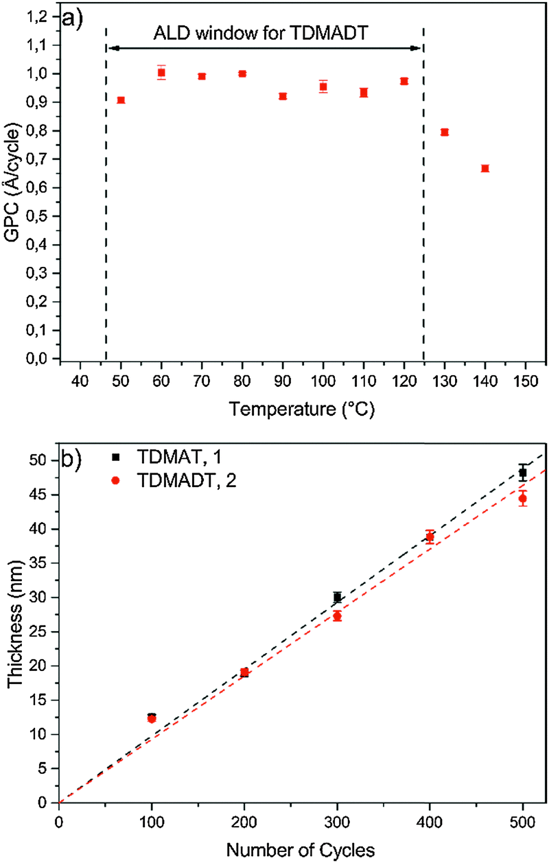 | ||
| Fig. 5 Growth characteristics: (a) ALD window of TDMADT, (b) thickness of thin films vs. applied number of cycles at 60°. All depositions were carried out on Si(100). | ||
Furthermore, an ALD window is usually not observed for PE-ALD processes, as the plasma contributes to the whole process with several new parameters, thus affecting the typical ALD behavior. Highly reactive plasma species are also formed among the adsorbed precursor molecules at the substrate, leading to surface migration, reactions, desorption and decomposition. Therefore, if an ALD window is observed during a PE-ALD process, it is even more indicative that the nature of the process is truly following an ALD mechanism, where surface saturation without gas phase precipitation, gas phase reaction or precursor decomposition takes place.
Thickness dependence as a function of ALD cycles was investigated in the range of 100–500 cycles and the data are shown in Fig. 5b. For TDMADT, a GPC of (0.93 ± 0.02) Å per cycle is obtained from the slope of the linear fit for thickness vs. cycles. Applying the same process parameters, GPC increases with 11% for TDMAT to 1.0 Å per cycle. The low standard deviation (error bars) indicates a reproducible layer growth process for both precursors. Furthermore, high homogeneity over the whole substrate is achieved, indicated by a non-uniformity of only 0.2% on a 45 nm thick film, deposited using TDMADT. Taking into account the relation of molecular masses and frequency shifts from QCM saturation studies, it can be assumed that nearly the same amount of precursor molecules adsorbs during one cycle on the surface, resulting in nearly similar GPC.
The growth behavior was further investigated regarding the influence of the plasma pulse length. Fig. 6 shows the GPC values for TDMAT and TDMADT with variation of the oxygen plasma pulse.
 | ||
| Fig. 6 Growth per cycle under variation of plasma pulse length for both precursors. | ||
When the substrate is exposed to a plasma step of 100 ms or shorter, the growth rates for both precursors are rather high with 1.3 Å per cycle and 0.98 Å per cycle for TDMAT and TDMADT, respectively. For a plasma pulse of 150 ms, a stronger decrease in GPC is found for TDMAT than for TDMADT, indicating a higher stability of the new precursor towards the applied plasma. For both compounds, a plateau in the growth rate can be found between 150 ms and 300 ms, where in both cases the growth rate is 0.8 Å per cycle. As the plasma oxidizes the ligands of the used Ti-precursors to form TiO2, high growth rates for short plasma pulses are most likely connected to higher amounts of impurities due to insufficient combustion of the ligands.
Thin film characteristics
The surface features of thin films deposited on Si substrates were investigated by AFM in terms of RMS roughness, and representative AFM images of 24 nm thin films deposited at 60 °C on silicon with an oxygen flow rate of 25 sccm and a plasma pulse length of 150 ms are shown in Fig. 7.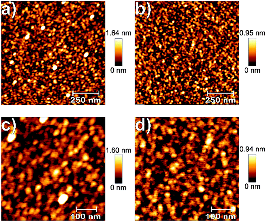 | ||
| Fig. 7 1 μm × 1 μm (a and c) and 500 nm × 500 nm (b and d) AFM scans of TiO2 thin films (24 nm), deposited on Si(100) at 60 °C using TDMAT (a and b) and TDMADT (c and d). | ||
From each sample, 1 μm × 1 μm and 500 nm × 500 nm scans were performed. For both precursors, low RMS roughness values, irrespective of the scan size, of 0.36 nm (TDMAT, 1) and 0.22 nm (TDMADT, 2) were found, matching findings from other PE-ALD applications employing TDMAT with RMS roughness values of 0.2–0.31 nm.46,47 For TDMAT, AFM revealed the formation of more distinctive hillocks with a height of about 1.6 nm while thin films deposited using TDMADT show a maximum height of only 0.95 nm for surface structures. For both precursors, the formation of single grains is observed, indicating the tendency of both compounds to agglomerate at several nucleation sites during film growth. As the bare silicon substrate exhibits a RMS roughness of 0.22 nm, a true ALD process during which the surface topology of the substrate is mimicked by the growing thin film can be assumed. Interestingly, this finding is even more distinctive for the new precursor TDMADT, as the thin film and the bare substrate show the same roughness.
The composition of the deposited thin films was determined employing RBS and NRA. RBS experiments allow the detection of heavier elements like Si and metals, whereas lighter elements like C and N were detected by means of NRA measurements (Table 1). As growth rates were found to be temperature-independent within the range from 60 °C to 120 °C, thin films deposited at these temperatures (within the ALD window) were investigated to ensure consistency in composition. Measured and respective simulated RBS spectra are shown in Fig. 8. Besides titanium (1439 keV), silicon (substrate, 1139 keV) and oxygen (730 keV), no other elements were detected. From the spectra in Fig. 8, it is evident that at both deposition temperatures the thin film composition is consistent within the ALD window.
| Pulse length (ms) | Flow rate (sccm) | TDMAT, 1 | TDMADT, 2 | ||||||||
|---|---|---|---|---|---|---|---|---|---|---|---|
| Amount (at%) and stoichiometry of deposited TiO2 thin films | |||||||||||
| C | N | O | Ti | O/Ti | C | N | O | Ti | O/Ti | ||
| 0.0 = not detected species with detection limits for C and N of 1.7 × 10¹⁴ atoms per cm3 and 2.0 × 10¹⁵ atoms per cm3, respectively. In all cases, an error of about 1.5 at% must be assumed. | |||||||||||
| 50 | 15 | 23.5 | 20.3 | 41.4 | 14.8 | 2.80 | 12.9 | 14.7 | 52.3 | 20.1 | 2.60 |
| 100 | 21.2 | 20.9 | 43.2 | 14.7 | 2.94 | 7.3 | 5.4 | 60.2 | 27.1 | 2.22 | |
| 150 | 13.0 | 17.2 | 51.8 | 18.0 | 2.90 | 1.7 | 0.0 | 67.6 | 30.7 | 2.20 | |
| 200 | 0.5 | 2.1 | 64.4 | 33.0 | 1.95 | 0.0 | 0.0 | 66.3 | 33.7 | 1.97 | |
| 250 | 1.90 | 0.0 | 66.1 | 31.9 | 2.07 | 0.6 | 0.0 | 68.3 | 31.1 | 2.20 | |
| 300 | 1.9 | 0.0 | 66.7 | 31.4 | 2.12 | 0.0 | 0.0 | 67.2 | 32.8 | 2.05 | |
| 400 | 0.3 | 0.5 | 65.9 | 33.3 | 1.98 | 0.6 | 0.0 | 67.0 | 32.4 | 2.07 | |
| 100 | 15 | 21.2 | 20.9 | 43.2 | 14.7 | 2.94 | 7.3 | 5.4 | 60.2 | 27.1 | 2.22 |
| 25 | 2.6 | 3.7 | 63.5 | 30.2 | 2.10 | 1.8 | 0.0 | 66.6 | 31.6 | 2.11 | |
| 50 | 0.8 | 1.2 | 65.6 | 32.4 | 2.02 | 1.9 | 0.3 | 66.2 | 31.6 | 2.09 | |
 | ||
| Fig. 8 RBS spectra of 25 nm thick TiO2 thin films, deposited on Si(100) using TDMADT and oxygen plasma. | ||
As it is known that the plasma pulse length and the oxygen flow rate, i.e. the amount of oxygen during plasma ignition, do have a strong influence on thin film composition, detailed analysis was carried out on respective deposition series and the results are listed in Table 1.
For depositions investigating the influence of the plasma pulse length, the oxygen flow rate was kept constant at 15 sccm. For both precursors, plasma pulse length ≤100 ms yields thin films with high amounts of carbon and nitrogen and the ratio of titanium to oxygen is well above 2.0 and the formation of carbide and nitride species must be assumed. For a plasma pulse of 150 ms, impurities in the thin films grown from TDMAT are still high with 13.0 at% (C) and 17.2 at% (N), respectively. For a 150 ms plasma pulse, TDMADT yields only minor contaminations of 1.7 at% (C) while nitrogen was not detected. Thin films deposited applying a plasma pulse of ≥200 ms show low impurities for both carbon and nitrogen up to 2 at% and nearly perfect stoichiometry, irrespective of the chosen precursors. For TDMAT, a higher oxygen flow rate leads to a significant increase in the oxygen content of the thin films from 43.2% to 63.5%. Using TDMADT yields high oxygen contents already at low flow rates. In addition, using TDMADT yields nearly stoichiometric thin films even at low oxygen flow rates with an O/Ti ratio of 2.2.
The surface chemical composition of representative samples, deposited with 150 ms and 200 ms plasma pulse length, was further characterized using angle-resolved XPS. O/Ti ratios and amounts of C and N in at% are shown in Table 2.
| Precursor | Pulse length (ms) | C1s (at%) | N1s (at%) | O1s (at%) | Ti2p (at%) | O/Tia |
|---|---|---|---|---|---|---|
| a Calculation based on the oxide component of the O1s signal at 530.0 eV as derived from the corresponding core level spectra. | ||||||
| 15° emission angle | ||||||
| TDMAT | 150 | 28.7 | 2.0 | 49.7 | 19.6 | 1.8 |
| TDMADT | 150 | 28.1 | 1.9 | 50.0 | 19.9 | 1.8 |
| TDMAT | 200 | 27.6 | 2.1 | 50.3 | 20.0 | 1.8 |
| TDMADT | 200 | 27.0 | 1.5 | 51.2 | 20.4 | 1.7 |
| 60° emission angle | ||||||
| TDMAT | 150 | 42.3 | 1.9 | 40.5 | 15.3 | 1.7 |
| TDMADT | 150 | 40.0 | 2.1 | 42.3 | 15.7 | 1.8 |
| TDMAT | 200 | 40.5 | 2.6 | 41.7 | 15.2 | 1.7 |
| TDMADT | 200 | 41.0 | 1.7 | 41.4 | 15.8 | 1.6 |
Around 2 at% of N was found throughout the samples at both take-off angles and is thus associated with bulk N originating from the precursors. In this regard, the N atomic fraction was observed to be decreased to ≤2 at% at 200 ms pulse length when using TDMADT. The O/Ti ratios are found to be around 1.8 (15°) and 1.7 (60°). The deviation of the O/Ti ratio from the expected value of 2 is within the limit of error, taking into consideration that the adventitious carbon surface layer is known to affect XPS quantification.48 High resolution core level spectra were measured and are shown in Fig. 9.
 | ||
| Fig. 9 Representative high resolution XPS spectra of a 24 nm TiO2 thin film on Si(100), deposited at 60 °C using TDMADT and 200 ms oxygen plasma pulse. (a) Ti2p, (b) O1s, (c) N1s and (d) C1s core levels. | ||
The C1s spectrum can be assigned to three carbon species peaks: aliphatic C at 284.8 eV, COH and α-carbon of carboxylic acids at 285.8 eV, and carboxylic acids at 288.5 eV. The Ti2p spectrum was described by a single doublet corresponding to TiO2 with the Ti2p3/2 component at a binding energy of 458.6 eV.49 The O1s exhibited one component at 530.0 eV, which can be assigned to TiO2, and a second component at 531.3 eV, which is typical for either surface hydroxylation or O bound to adventitious carbon.49,50 The O content bound to adventitious carbon as derived from the C1s spectra amounted to around 30% of the C atomic fraction, which matched quantitatively the atomic fraction of the higher binding energy O1s signal. Thus, the O1s component located at 531.3 eV can be said to be dominated by adventitious carbon without significant evidence of hydroxylation. The N1s core level revealed a single N component at 400.7 eV, which was assigned to interstitial N.51
From the results based on the aforementioned process optimization in terms of substrate temperature, the deposition of TiO2 thin films using TDMADT on polymer substrates is promising with respect to application as gas barrier coating. Results from preliminary studies on barrier performance in terms of OTR of TiO2 thin films are shown in Fig. 10.
 | ||
| Fig. 10 OTR for TiO2 thin films on PET foil (RD 23). OTR for zero cycles is the OTR of the uncoated foil and was measured to be 76.64 cm3 × m−2 × day−1. | ||
For both precursors, respective analysis was carried out on deposition series with increasing number of cycles, where the range from 20 cycles to 150 cycles was of particular interest. A significant change in barrier performance was not observed for thin films deposited with less than 60 cycles (6 nm and 5.6 nm for TDMAT and TDMADT, respectively). Irrespective of the chosen precursor, thin films showed OTRs in the range of the uncoated PET foil of about 70 cm3 × m−2 × day−1. Interestingly, using TDMADT (2) causes an initial slight drop in OTR after 80 cycles (7.4 nm), while the barrier performance for films deposited using TDMAT (1) remains in the order of the uncoated foil. For 100 cycles (9.3 nm and 10 nm for TDMAT and TDMADT, respectively), thin films from TDMAT show better barrier performance than those deposited from TDMADT. A critical thickness, i.e. a drop of at least two orders of magnitude in OTR,52 is found in both cases when 150 cycles (15 nm for TDMAT and 14 nm for TDMADT) are applied. At this point, differences in the OTR of thin films obtained from the two different precursors are very low. Despite a good barrier performance in terms of OTR for films originating from both precursors below 0.2 cm3 × m−2 × day−1, a different nucleation for the two precursors during the first cycles must be assumed, indicated by the discrepancy in OTR values for 80 and 100 cycles. This is also in agreement with AFM results, where thin films from TDMAT show the formation of stronger pronounced hillocks. However, titanium dioxide gas barrier layers with promising performance were successfully deposited on PET substrates using the new compound TDMADT and a critical thickness of dc = 14 nm was found. In comparison with other ALD gas barrier layers, the performance of our coatings is in good agreement with reported values from the literature. For example, a pure TiO2 thin film of 10 nm thickness on LDPE results in an OTR of 10.0 cm3 × m−2 × day−1.53 In contrast to this, a 128 nm coating of Al2O3 is needed to achieve a barrier coating of 2.0 cm3 × m−2 × day−1 on PET.53
Conclusions
Using the new compound TDMADT, [Ti(NMe2)3(dmap)], we successfully demonstrated an efficient PE-ALD process to deposit TiO2 thin films at low temperatures (60 °C), allowing depositions on polymers with low melting points such as PET. The new precursor exhibits high volatility, higher thermal stability compared to TDMAT and a fine-tuned reactivity, resulting in a high growth rate of 0.93 Å per cycle. In situ QCM analysis of PE-ALD experiments revealed a sufficient surface saturation even for very short precursor pulse times of only 2 × 40 ms and the presence of the dmap-ligand after surface adsorption. Temperature-independent growth was found in an ALD window between 60 and 120 °C for an optimized PE-ALD process using the new compound, exhibiting a high growth rate of 0.92 Å per cycle. In addition, studies on the thickness vs. number of cycles prove the principle of a true, self-limiting ALD process. Coatings from PE-ALD on silicon were found to be amorphous over the whole temperature range of the ALD window and in comparison to the often used precursor TDMAT, RBS/NRA and XPS revealed the good suitability of this precursor in PE-ALD with regard to thin film composition, exhibiting extremely low amounts of carbon and nitrogen (≤2 at%). An explanation for this observation could be that the new titanium-complex TDMADT already comprises a titanium–oxygen bond, thus facilitating the formation of an inorganic thin film more likely at an earlier stage of the PE-ALD process compared to TDMAT, which is an all-nitrogen-coordinated complex. From AFM investigations on 24 nm thick samples, RMS roughness was determined to be 0.22 nm, revealing highly smooth films. From our experiments, the new compound facilitates the formation of TiO2 thin films due to the presence of a Ti–O bond within the precursor. From this, films of higher quality can be obtained in a less processing time. Finally, preliminary studies on the gas barrier performance of TiO2 thin films deposited from TDMADT on PET substrates show promising results regarding OTR, since values were found to be as low as 0.12 cm3 × m−2 × day−1 for a critical thickness of about 14 nm.Acknowledgements
All authors gratefully acknowledge the German Research Foundation (DFG) for supporting this work (SFB-TR 87). The authors would like to thank all members of the special research unit SFB-TR 87. The authors want to thank Dr Detlef Rogalla from the Dynamitron Tandem Laboratory (DTL) of RUBION, Central Unit for Ion Beams and Radionuclides, for performing RBS and NRA measurements.Notes and references
- S. Banerjee, D. D. Dionysiou and S. C. Pillai, Appl. Catal., B, 2015, 176–177, 396 CrossRef CAS.
- H. Çamurlu, Ö. Kesmez, E. Burunkaya, N. Kiraz, Z. Yeşil, M. Asiltürk and E. Arpa, Chem. Pap., 2012, 66, 461 Search PubMed.
- V. C. Anitha, A. Banerjee and S. Joo, J. Mater. Sci., 2015, 50, 7495 CrossRef CAS.
- Y. Bai, I. Mora-Seró, F. De Angelis, J. Bisquert and P. Wang, Chem. Rev., 2014, 114, 10095 CrossRef CAS PubMed.
- T. Ahmadzada, D. R. McKenzie, N. L. James, Y. Yin and Q. Li, Thin Solid Films, 2015, 591(part A), 131 CrossRef CAS.
- J. Fahlteich, M. Fahland, W. Schönberger and N. Schiller, Thin Solid Films, 2009, 517, 3075 CrossRef CAS.
- M. Aghaee, P. S. Maydannik, P. Johansson, J. Kuusipalo, M. Creatore, T. Homola and D. C. Cameron, J. Vac. Sci. Technol., A, 2015, 33, 041512 Search PubMed.
- J. Fahlteich, W. Schönberger, M. Fahland and N. Schiller, Surf. Coat. Technol., 2011, 205, S141 CrossRef CAS.
- J.-S. Park, H. Chae, H. K. Chung and S. I. Lee, Semicond. Sci. Technol., 2011, 26, 034001 CrossRef.
- G. L. Graff, R. E. Williford and P. E. Burrows, J. Appl. Phys., 2004, 96, 1840 CrossRef CAS.
- Y. Leterrier, Prog. Mater. Sci., 2003, 48, 1 CrossRef CAS.
- K. Bahroun, H. Behm, F. Mitschker, P. Awakowicz, R. Dahlmann and H. Ch, J. Phys. D: Appl. Phys., 2014, 47, 015201 CrossRef.
- H. Bahre, K. Bahroun, H. Behm, S. Steves, P. Awakowicz, M. Böke, H. Ch and J. Winter, J. Phys. D: Appl. Phys., 2013, 46, 084012 CrossRef.
- S. McDonnell, R. C. Longo, O. Seitz, J. B. Ballard, G. Mordi, D. Dick, J. H. G. Owen, J. N. Randall, J. Kim, Y. J. Chabal, K. Cho and R. M. Wallace, J. Phys. Chem. C, 2013, 117, 20250 CAS.
- P. Schindler, M. Logar, J. Provine and F. B. Prinz, Langmuir, 2015, 31, 5057 CrossRef CAS PubMed.
- S.-H. Jen, J. A. Bertrand and S. M. George, J. Appl. Phys., 2011, 109, 084305 CrossRef.
- P. F. Carcia, R. S. McLean, M. D. Groner, A. A. Dameron and S. M. George, J. Appl. Phys., 2009, 106, 023533 CrossRef.
- T. Hirvikorpi, M. Vähä-Nissi, T. Mustonen, E. Iiskola and M. Karppinen, Thin Solid Films, 2010, 518, 2654 CrossRef CAS.
- E. Langereis, M. Creatore, S. B. S. Heil, M. C. M. van de Sanden and W. M. M. Kessels, Appl. Phys. Lett., 2006, 89, 081915 CrossRef.
- H. B. Profijt, S. E. Potts, M. C. M. van de Sanden and W. M. M. Kessels, J. Vac. Sci. Technol., A, 2011, 29, 050801 Search PubMed.
- D. Shi, J. Lian, P. He, L. M. Wang, W. J. van Ooij, M. Schulz, Y. Liu and D. B. Mast, Appl. Phys. Lett., 2002, 81, 5216 CrossRef CAS.
- O. Gourhant, G. Gerbaud, A. Zenasni, L. Favennec, P. Gonon and V. Jousseaume, J. Appl. Phys., 2010, 108, 124105 CrossRef.
- M. A. Cameron, I. P. Gartland, J. A. Smith, S. F. Diaz and S. M. George, Langmuir, 2000, 16, 7435 CrossRef CAS.
- M. Tallarida, D. Friedrich, M. Städter, M. Michling and D. Schmeisser, J. Nanosci. Nanotechnol., 2011, 11, 8049 CrossRef CAS PubMed.
- R. Katamreddy, V. Omarjee, B. Feist and C. Dussarrat, ECS Trans., 2008, 16, 113 CAS.
- Z. Rao, J. Wan, C. Li, B. Chen, J. Liu, C. Huang and Y. Xia, Plasma Sci. Technol., 2014, 16, 239 CrossRef CAS.
- J. P. Lee, M. H. Park, T.-M. Chung, Y. Kim and M. M. Suung, Bull. Korean Chem. Soc., 2004, 25, 475 CrossRef CAS.
- M. Rose, J. Niinistö, P. Michalowski, L. Gerlich, L. Wilde, I. Endler and J. W. Bartha, J. Phys. Chem. C, 2009, 113, 21825 CAS.
- M. Kaipio, T. Blanquart, Y. Tomczak, J. Niinistö, M. Gavagnin, V. Longo, H. D. Wanzenböck, V. R. Pallem, C. Dussarrat, E. Puukilainen, M. Ritala and M. Leskelä, Langmuir, 2014, 30, 7395 CrossRef CAS PubMed.
- R. Matero, A. Rahtu and M. Ritala, Chem. Mater., 2001, 13, 4506 CrossRef CAS.
- S. p. Larouche, H. Szymanowski, J. E. Klemberg-Sapieha, L. Martinu and S. C. Gujrathi, J. Vac. Sci. Technol., A, 2004, 22, 1200 CAS.
- S. Ratzsch, E. B. Kley, A. Tunnermann and A. Szeghalmi, Nanotechnology, 2015, 26, 024003(1) CrossRef PubMed.
- W.-S. Kim, M.-G. Ko, T.-S. Kim, S.-K. Park, Y.-K. Moon, S.-H. Lee, J.-G. Park and J.-W. Park, J. Nanosci. Nanotechnol., 2008, 8, 4726 CrossRef CAS PubMed.
- Q. Xie, J. Musschoot, D. Deduytsche, R. L. Van Meirhaeghe, C. Detavernier, S. Van den Berghe, Y.-L. Jiang, G.-P. Ru, B.-Z. Li and X.-P. Qu, J. Electrochem. Soc., 2008, 155, H688 CrossRef CAS.
- L. H. Kim, K. Kim, S. Park, Y. J. Jeong, H. Kim, D. S. Chung, S. H. Kim and C. E. Park, ACS Appl. Mater. Interfaces, 2014, 6, 6731 CAS.
- M. Banerjee, V.-S. Dang, M. Bledowski, R. Beranek, H.-W. Becker, D. Rogalla, E. Edengeiser, M. Havenith, A. D. Wieck and A. Devi, Chem. Vap. Deposition, 2014, 20, 224 CrossRef CAS.
- V.-S. Dang, H. Parala, J. H. Kim, K. Xu, N. B. Srinivasan, E. Edengeiser, M. Havenith, A. D. Wieck, T. de los Arcos, R. A. Fischer and A. Devi, Phys. Status Solidi A, 2014, 211, 416 CrossRef CAS.
- D. C. Bradley and I. M. Thomas, J. Chem. Soc., 1960, 3857, 10.1039/JR9600003857.
- D. Nečas and P. Klapetek, Cent. Eur. J. Phys., 2012, 10, 181 Search PubMed.
- M. Mayer, AIP Conf. Proc., 1999, 475, 541 CrossRef CAS.
- A. C. Jones, T. J. Leedham, P. J. Wright, M. J. Crosbie, K. A. Fleeting, D. J. Otway, P. O'Brien and M. E. Pemble, J. Mater. Chem., 1998, 8, 1773 RSC.
- A. Szeghalmi, M. Helgert, R. Brunner, F. Heyroth, U. Gösele and M. Knez, J. Opt. Soc. Am., 2009, 48, 1727 CAS.
- H. Y. Jeong, J. Y. Lee, M.-K. Ryu and S.-Y. Choi, Phys. Status Solidi RRL, 2010, 4, 28 CrossRef CAS.
- M. R. Saleem, R. Ali, S. Honkanen and J. Turunen, Thin Solid Films, 2013, 542, 257 CrossRef CAS.
- D.-S. Han, D.-K. Choi and J.-W. Park, Thin Solid Films, 2014, 552, 155 CrossRef CAS.
- G. X. Liu, F. K. Shan, W. J. Lee and B. C. Shin, J. Korean Phys. Soc., 2007, 50, 1827 CrossRef CAS.
- D. Saha, R. S. Ajimsha, K. Rajiv, C. Mukherjee, M. Gupta, P. Misra and L. M. Kukreja, Appl. Surf. Sci., 2014, 315, 116 CrossRef CAS.
- G. C. Smith, J. Electron Spectrosc. Relat. Phenom., 2005, 148, 21 CrossRef CAS.
- U. Diebold and T. E. Madey, Surf. Sci. Spectra, 1996, 4, 227 CrossRef CAS.
- M. C. Biesinger, L. W. M. Lau, A. R. Gerson and R. S. C. Smart, Appl. Surf. Sci., 2010, 257, 887 CrossRef CAS.
- C. Di Valentin, G. Pacchioni, A. Selloni, S. Livraghi and E. Giamello, J. Phys. Chem. B, 2005, 109, 11414 CrossRef CAS PubMed.
- A. S. da Silva Sobrinho, M. Latèche, G. Czeremuszkin, J. E. Klemberg-Sapieha and M. R. Wertheimer, J. Vac. Sci. Technol., A, 1998, 16, 3190 CAS.
- T. O. Kääriäinen, P. Maydannik, D. C. Cameron, K. Lahtinen, P. Johansson and J. Kuusipalo, Thin Solid Films, 2011, 519, 3146 CrossRef.
Footnote |
| † Electronic supplementary information (ESI) available. See DOI: 10.1039/c5tc03385c |
| This journal is © The Royal Society of Chemistry 2016 |