 Open Access Article
Physicochemical fabrication of calcium phosphate-based thin layers and nanospheres using laser processing in solutions
Maki
Nakamura
* and
Ayako
Oyane
*
Nanomaterials Research Institute, National Institute of Advanced Industrial Science and Technology (AIST), Central 5, 1-1-1, Higashi, Tsukuba, Ibaraki 305-8565, Japan. E-mail: ma-ki-nakamura@aist.go.jp; a-oyane@aist.go.jp
First published on 22nd August 2016
Abstract
Calcium phosphate (CaP)-based thin layers and nanospheres have various potential biomedical applications. This paper describes the laser-assisted fabrication of CaP-based thin layers and nanospheres, with a focus on a new physicochemical process developed by us. This process is conducted under normal pressure and temperature in supersaturated CaP solutions using pulsed laser irradiation. Owing to the light-mediated solid–liquid interactions, this process enables the simple and rapid fabrication of CaPs. In addition, the physicochemical and biological properties of CaPs can be controlled by manipulating the processing conditions. Our physicochemical process provides a new tool for fabricating CaP-based thin layers and nanospheres for biomedical applications.
1. Introduction
1.1 Fundamentals of calcium phosphates
Calcium phosphates (CaPs) are the main mineral components found in human bones and teeth. They are synthesized naturally in living organisms via biomineralization and are also fabricated via artificial processes outside the human body. As already summarized in a number of recent reviews,1–11 there exist various types of CaP compounds that possess different crystalline phases, chemical formulas, Ca/P molar ratios, and solubilities. Most CaPs are sparingly or hardly soluble in neutral water but all CaPs dissolve in acids. Among CaP compounds, hydroxyapatite (HAp, Ca10(PO4)6(OH)2, Ca/P = 1.67)3–6 is the most stable and insoluble phase in the physiological environment. Moreover, HAp is similar to the mineral component found in bones and teeth. Some CaPs such as octacalcium phosphate (OCP, Ca8(HPO4)2(PO4)4·5H2O, Ca/P = 1.33)12 are found as intermediate phases during biomineralization. Amorphous calcium phosphate (ACP, CaxHy(PO4)z·nH2O (n = 3–4.5), Ca/P = 1.2–2.2)13 is also a precursor of HAp and appears in the initial stage of biomineralization. Compared with well-crystallized HAp, OCP and ACP have relatively higher solubilities.1.2 Biological properties and applications of CaPs
Some CaPs, including sintered HAp and β-tricalcium phosphate (β-TCP, β-Ca3(PO4)2, Ca/P = 1.5), show good biocompatibility, i.e., they are generally nontoxic and induce minimal inflammatory or foreign-body reactions. Unlike other general artificial materials, they are not encapsulated by fibrous tissues, and bond directly to the living bone tissues. This property is referred to as bone-bonding ability or osteoconductivity. On these osteoconductive CaP surfaces, bone cells adhere and proliferate, and finally a new bone is formed and interacts with the surrounding bone tissues. In addition to osteoconductivity, some CaPs such as sintered carbonate apatite and β-TCP show bioresorbability, i.e., they are dissolved in the body and replaced with the bone tissue over time. Because of these useful biological properties, CaPs in various compositions and forms have been used in orthopedic and dental applications.8,11,14,15 For example, sintered HAp, β-TCP, and α-TCP (α-Ca3(PO4)2, Ca/P = 1.5) and their composites have been used as bone substitutes, bone cement powders, bone fillers, and osteoconductive coatings on implants.Some CaPs also show high affinity for specific drugs, proteins, antibodies, and nucleic acids (DNA, RNA). In addition, the component ions (calcium, phosphate, and hydroxide ions) in CaPs are easily replaced by other inorganic ions.2,16–18 Therefore, CaPs have also been used as column beads for chromatography,19,20 adsorbents for organic and metallic pollutants,21,22 and transfection reagents for cells.23–25 In recent years, delivery of therapeutic and diagnostic agents using CaP nanoparticles has been intensively studied for developing multifunctional CaP-based nanocarriers.3,26–28
1.3 CaP thin layers and nanospheres
Bulk CaP ceramics are generally manufactured by sintering row CaP powder compacts. However, sintered bulk CaP ceramics are extremely hard and brittle; hence, they can be used only under low-load-bearing conditions. Coating thin layers of CaPs on different artificial materials (e.g., tough and strong metallic materials or soft and flexible polymeric materials) is an effective approach to produce biocompatible and osteoconductive composites that can be used under various conditions.10,29–33 Thus, the CaP coating technique is important for expanding the use and practical application of CaPs and for functionalizing the surfaces of artificial materials.The fabrication of CaP-based nanospheres is also becoming increasingly important because of the high potential of CaP-based nanospheres as safe and biocompatible delivery carriers for therapeutic and diagnostic agents.3,26–28 CaP-based nanospheres show potential as carriers because nano-sized particles can penetrate into tiny interstices in a body, be administered by injection, travel through the bloodstream, and permeate cell membranes and blood vessel walls if particle structures and surface functionalities are appropriate. CaP carriers comprising human biomineral components have the advantages of biocompatibility, low toxicity, pH sensitivity (degradable under acidic conditions into serum ions), and cost-effectiveness (sources are ubiquitous elements). Owing to these potentials and advantages, CaP-based nanospheres with various compositions and structures (solid, hollow, and core–shell) have recently been developed for use in delivery carrier applications.34–37
1.4 Fabrication of CaP thin layers and nanospheres
Conventionally, CaP-based thin layers and nanoparticles have been fabricated by either physical or chemical process (this will be described in more detail later). Recently, we developed a new physicochemical process for the fabrication of CaP-based thin layers38–42 and nanospheres43,44 by combining a physical laser process and a chemical precipitation process. In this process, pulsed laser irradiation is performed without focusing to a metastable or labile supersaturated CaP solution to induce light–material interactions at a laser-irradiated substrate surface (for thin layer fabrication) or in the entire solution (for sphere fabrication) (Fig. 1). In the process of thin layer fabrication, bulk substrates immersed in a metastable supersaturated CaP solution function as both a light-absorbing agent and a frame to support the CaP layer (Fig. 1, lower left). In the process of sphere fabrication, metal ions incorporated within the dispersed nano-precipitates function as light-absorbing agents in a labile supersaturated CaP solution (Fig. 1, lower right).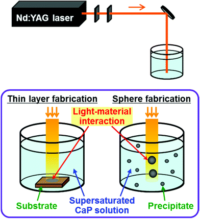 | ||
| Fig. 1 Schematic illustration of our physicochemical process: laser irradiation system (upper), thin layer fabrication (lower left), and sphere fabrication (lower right). | ||
This review summarizes the fabrication processes of CaP-based thin layers (Section 2) and spheres (Section 3), focusing on our physicochemical process via laser processing in supersaturated CaP solutions. In this review, a nanosphere is defined as a particle with a diameter of 1–1000 nm.
2. Physicochemical fabrication of CaP-based thin layers
2.1 CaP coating techniques
A conventional biomimetic process is generally carried out in a sequence of steps that include the surface modification of a substrate and the immersion of the surface-modified substrate in a supersaturated CaP solution such as a simulated body fluid (SBF).48,49 In the surface-modification step, the surface of a substrate is modified with hydrophilic functional groups (e.g., Si–OH, Ti–OH, COOH, and SO3H) and/or CaP seeds. In the subsequent immersion step, the surface-modified substrate is immersed in a supersaturated CaP solution to grow a CaP layer on the surface. When certain biofunctional substances are added to the supersaturated CaP solution at appropriate concentrations, they are spontaneously incorporated into the CaP layer via coprecipitation, providing various biological functions.25,45–47
A critical disadvantage of conventional biomimetic processes is their impracticality; they are usually time-consuming (hours to days) due to the multiple steps, including a complicated surface-modification step, and the relatively low growth rate of CaP. To overcome this disadvantage, physical stimulation (e.g., laser irradiation,50–54 ultraviolet (UV) irradiation,55,56 and microwave irradiation57–60) has been introduced into biomimetic processes. In this review, we focus on the laser irradiation, specifically, laser processing in a supersaturated CaP solution. This process combines a physical laser process and a chemical precipitation process in a single step, which enables rapid and area-specific CaP precipitation at the laser-irradiated solid–liquid interface (i.e., the interface between a substrate and a metastable supersaturated CaP solution). Laser stimulation was initially applied as a CaP-precoating method before the immersion step in supersaturated CaP solution.50–54 Such two-step CaP coating techniques are described in Section 2.2. Recently, these two-step techniques have been refined, and one-step CaP coating was achieved using a laser-assisted biomimetic (LAB) process;38–42 this process is described in detail in Section 2.3.
2.2 Laser-assisted two-step CaP coating techniques
 | ||
| Fig. 2 Laser-assisted two-step biomimetic process using the EVOH substrate. (a) Schematic illustration. (b) Optical microscopy (upper right) and scanning electron microscopy (SEM) images of the laser-irradiated (lower right) and non-irradiated (upper left) surfaces of the EVOH substrate after laser irradiation for 3 h and subsequent immersion in CP solution for 24 h (modified from ref. 54 with permission). | ||
2.3 Laser-assisted one-step CaP coating technique: LAB process
 | ||
| Fig. 3 LAB process using the EVOH substrate. (a) Schematic illustration. (b) Optical microscopy (upper left) and SEM images of the laser-irradiated (upper right) and non-irradiated (lower left) surfaces of the EVOH substrate after laser irradiation (200 mJ per pulse per cm2) in CP solution for various periods of time (10, 20, and 30 min) (modified from ref. 38 with permission). | ||
Our CaP coating technique using the LAB process is carried out rapidly in one step without a prior surface-modification step or a post-immersion step in supersaturated CaP solution. These characteristics represent advantages over the conventional two-step biomimetic CaP coating techniques.
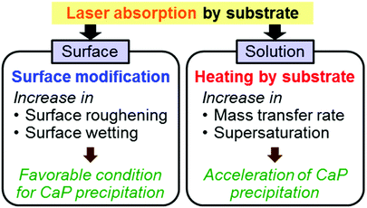
First, we performed the same UV laser irradiation but without a temperature-controlled water bath to amplify the heating effect on the EVOH substrate. As shown in Fig. 5a, the temperature of the CP solution increased from its original temperature (25 °C) with increasing irradiation time of the EVOH substrate. In the absence of the substrate, the temperature increase of the same solution was negligible (Fig. 5a) because the CP solution absorbs very little light at 355 nm. Therefore, the increased temperature in the presence of the EVOH substrate must be due to laser absorption by the substrate and the resulting selective heating via light-to-heat energy conversion at the surface. In fact, the EVOH substrate showed good light absorption at 355 nm (Fig. 5b). Even under the temperature control of the water bath (the normal conditions of the LAB process), the irradiated surface should be selectively heated to locally increase the temperature of the surrounding CP solution. This increase in temperature in the CP solution should have an accelerating effect on CaP nucleation and growth by increasing both the mass transfer rate and the degree of supersaturation of the solution with respect to CaPs (Fig. 4). Note that CaPs including HAp and OCP have lower solubilities at higher temperatures compared to at 25 °C, different from many other inorganic crystals.62,63
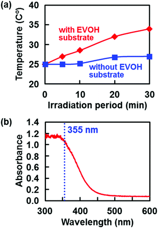 | ||
| Fig. 5 (a) Change in temperature of the CP solution without a temperature-controlled water bath during laser irradiation (200 mJ per pulse per cm2) with and without the EVOH substrate (modified from ref. 38 with permission). (b) Absorption spectrum of the EVOH substrate (modified from ref. 40 with permission). | ||
Second, laser irradiation was performed in ultrapure water to examine the structural changes in the surface of the base EVOH substrate. As shown in the SEM images in Fig. 6a, submicrometer-size pores formed on the EVOH surface after laser irradiation in ultrapure water. As the irradiation period in ultrapure water increased, the contact angle of water on the EVOH surface decreased (Fig. 6b). Similar surface reactions including surface roughening and wetting are expected to occur in the CP solution (normal conditions of the LAB process). The resulting submicroporous surface with increased wettability should provide a favorable environment for CaP precipitation in the CP solution.
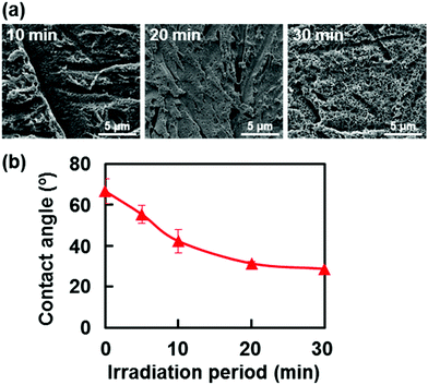 | ||
| Fig. 6 (a) SEM images of the laser-irradiated surfaces of the EVOH substrates after UV laser irradiation (200 mJ per pulse per cm2) in ultrapure water for various periods of time (10, 20, and 30 min). (b) Changes in the contact angle of water on the laser-irradiated surface of the EVOH substrate during UV laser irradiation (200 mJ per pulse per cm2) in ultrapure water (average ± standard deviation) (modified from ref. 38 with permission). | ||
As a result of the laser-induced surface modification and the selective heating described above, a CaP layer was formed specifically at the laser-irradiated solid–liquid interface on the EVOH substrate (Fig. 4).
We have tested four substrates in addition to EVOH: polyethylene terephthalate (PET, polymer), polyethylene (PE, polymer), sintered HAp (sHAp, ceramic), and titanium (Ti, metal). After the LAB process using UV laser (λ = 355 nm), CaP layers were formed on the PET,40 sHAp,39 and Ti substrates41,42 (Fig. 7), but not on the PE substrate.40 These results correlated well with the light absorption ability of the substrate at the employed laser wavelength (355 nm) and with the temperature change of the CP solution during laser irradiation of the substrate without a temperature-controlled water bath. For example, the PE substrate exhibited little light absorption at 355 nm and negligible heating of the CP solution under irradiation, thereby inducing no CaP precipitation during the LAB process.40 Conversely, other substrates including the EVOH substrate (Fig. 5b) showed higher light absorption at 355 nm than the PE substrate, resulting in a significant temperature increase of the CP solution under irradiation. Consequently, CaP precipitated on the EVOH, PET, sHAp, and Ti substrates by the LAB process using UV laser (λ = 355 nm) (Fig. 3b and 7).
 | ||
| Fig. 7 SEM images of the laser-irradiated surfaces of the PET, sHAp, and Ti substrates after the LAB process (133 mJ per pulse per cm2, 30 min) (modified from ref. 39–41 with permission). | ||
The mechanism underlying CaP precipitation in the LAB process should depend on the type of substrate due to the different light absorption abilities and surface chemistries of different substrates. The mechanism of CaP precipitation on the PET substrate is likely to be similar to that proposed for EVOH, which involves laser-induced surface modification (micro-deformation and wetting) and selective heating at the surface (Fig. 4). Our numerical estimates showed that the increases in surface temperatures of the EVOH and PET substrates by one pulse irradiation were just several degrees.40 Thus, nonthermal photochemical reactions might be involved in the laser-induced surface modification of these polymeric substrates in the LAB process. On the other hand, we estimated that the surface of the Ti substrate was heated up to several thousand degrees during one pulse irradiation during the LAB process.42 Therefore, the laser-induced surface modification of the Ti substrate should involve high-temperature processes such as melting, vaporization, ionization, and oxidization. In fact, the Ti surface was deformed and oxidized into the high-temperature phase (rutile) of titanium dioxide following laser irradiation. In the case of the ceramic sHAp substrate, which contains intrinsic CaP nucleation sites on its surface, CaP can precipitate on the sHAp surface in the supersaturated CP solution, even without any surface deformation.39 Laser irradiation simply accelerates CaP precipitation on the sHAp substrate through selective surface heating in the CP solution; laser irradiation does not affect the morphology of the sHAp surface under SEM observation. Due to such differences in CaP precipitation mechanism, the surface morphologies and crystalline phases of the CaP layers varied with substrate, even under the same irradiation conditions (laser fluence and irradiation time) (Fig. 7).
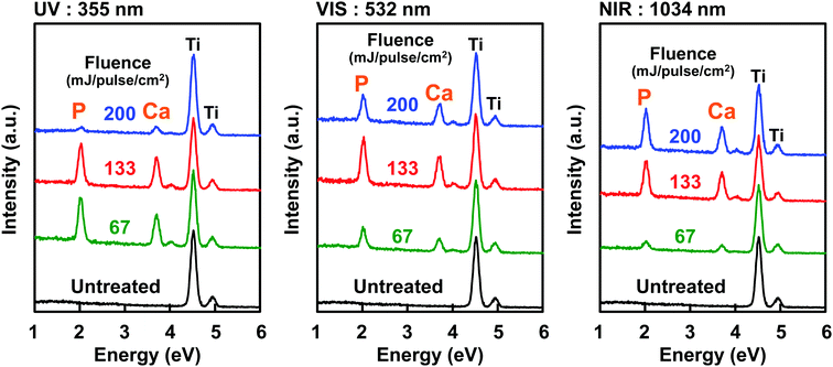 | ||
| Fig. 8 Energy dispersive X-ray analysis of the Ti substrate surfaces after the LAB process (30 min) using UV (left), VIS (center), and NIR (right) lasers with different fluences (67, 133, and 200 mJ per pulse per cm2) (modified from ref. 42 with permission). | ||
As a laser light, UV (355 nm), visible (VIS, 532 nm), and near-infrared (NIR, 1064 nm) lights of Nd:YAG laser were effective in inducing CaP precipitation on the Ti substrate using the LAB process.42 This occurred because Ti shows relatively high light absorption at a wide range of wavelengths from UV to NIR, although the light absorption rate depended on the wavelength. The effect of laser heating and consequently the amount (and crystalline structures as well) of the CaP precipitates varied with laser wavelength, even when laser fluence was kept constant (compare Ca/Ti ratio of the three substrates treated with the same fluence) (Fig. 8).
In the LAB process, a suitable laser wavelength should be selected according to the optical absorption properties of the intended substrate, and the laser fluence should be tuned to induce efficient CaP precipitation at the laser-irradiated surface of the substrate.
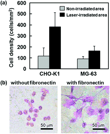 | ||
| Fig. 9 Preliminary cell adhesion studies. (a) Number densities of CHO-K1 and MG-63 cells (after 2 h of culture) adhering to the laser-irradiated and non-irradiated surfaces of the EVOH substrates after the LAB process (average ± standard deviation) (modified from ref. 38 with permission). (b) Optical microscopy images of CHO-K1 cells (after 24 h of culture) on the laser-irradiated surfaces of the Ti substrates after the LAB process in the CP solution supplemented with and without fibronectin (modified from ref. 41 with permission). | ||
In biomimetic processes, biological properties of CaP layers can be further improved or tailored by immobilizing certain biofunctional substances via the coprecipitation of CaP and biofunctional substances in supersaturated CaP solutions.25,45–47 Thus, we attempted to simultaneously immobilize biofunctional substances and precipitate CaP onto Ti substrates using the LAB process.41 As the biofunctional substances, we selected zinc, an essential trace element, and fibronectin, a cell-adhesion protein, both of which can act as osteogenic substances and stimulate bone regeneration.64–66 We supplemented the CP solution with ZnCl2 or fibronectin at various concentrations and performed the LAB process using Ti substrates and the modified CP solutions. After pulsed laser irradiation for 30 min, zinc or the components of fibronectin (molecules and/or their derivatives) along with CaP were present on the Ti surface. The contents of both zinc and the fibronectin components at the Ti surface were controllable by changing their initial concentrations in the modified CP solution. In the case of zinc, a cationic zinc ion was likely incorporated within the CaP nanocrystals through partial substitution at the calcium ion sites. In the case of fibronectin macromolecules, the experimental results suggested their partial degradation, aggregation, and/or denaturalization in the CP solution under the tested irradiation conditions. Despite this, the fibronectin components introduced on the Ti surface enhanced cell adhesion and spreading on the CaP-coated Ti substrate (Fig. 9b).41 This suggests that the fibronectin components provided active binding sites on the Ti surface, although it remains unclear whether these components were incorporated within the interstices of the CaP nanocrystals or adsorbed onto the precipitated CaP surface. From the perspective of the retention of native fibronectin structures and functions, posterior fibronectin adsorption onto the CaP-coated substrate would also be effective and probably more practical. The immobilization method should be carefully chosen and optimized in consideration of the types of biofunctional substances employed and the intended applications.
2.4 Challenges and perspective
As described above, the LAB process is a one-step, laser-assisted biomimetic CaP coating technique that allows the area-specific coating of CaP on various substrates with laser light absorption. The LAB process is carried out under normal pressures and temperatures in a pseudo-physiological supersaturated CaP solution. Hence, this process can be applied to polymeric substrates with low thermal durability as well as thermally durable metallic and ceramic substrates. Substrates that have been coated with CaPs by the LAB process include PET, sHAp, and Ti, all of which are important biomaterials used in medical and dental applications. Considering that the irradiation area is narrow (5 mm diameter circle) in our current system, the present LAB process should be suitable for small-sized biomaterials such as dental implants, bone screws, pins, and wires. The irradiation area could be expanded by rearranging the laser equipment, further broadening the application of the LAB process.Our new CaP coating technique using the LAB process has the potential to provide better clinical treatments. Since clinical treatments with lasers having various characteristics (pulse width, frequency, wavelength, etc.) have become popular in recent years,67–69 the LAB process might be utilized in medical settings for the preoperative or intraoperative surface functionalization of biomaterials. The CaP layers fabricated by the LAB process were composed mainly of OCP and/or HAp, both of which have been shown to exhibit good biocompatibility and osteoconductivity. Thus, our CaP coating technique using the LAB process has the potential to provide a target region of a biomaterial surface with good biocompatibility and osteoconductivity. Furthermore, biological properties of CaP layers can be further improved or tailored by immobilizing certain biofunctional substances, as demonstrated in Section 2.3.5. This might enable tailored medicine on demand from patients (e.g., zinc-incorporated CaP coating on bone fixation devices for osteoporotic fracture caused by zinc deficiency). These are challenges for future study.
3. Physicochemical fabrication of CaP-based nanospheres
3.1 Fabrication techniques of CaP-based nanoparticles
The disadvantage of the precipitation processes is the difficulty in controlling the shapes and sizes of the particles. Therefore, the precipitation process often requires specific surfactants for controlling nanoparticle shape and size,70,71 which in turn may cause safety issues for biomedical applications. Another approach without the use of surfactants is the application of physical stimulations such as laser irradiation, microwave irradiation,72–74 and ultrasonic irradiation.75
We have recently developed a surfactant-free, rapid (short irradiation time), and one-pot physicochemical process for fabricating CaP-based nanoparticles by combining a physical laser process with a chemical precipitation process.43,44 The resulting particles possess well-regulated spherical structures, which are advantageous for biomedical applications due to their reduced agglomeration, easy redispersion, and minimal physical irritation of cells, tissues, and organs. In the next section (Section 3.2), we introduce related previous studies on laser processing in liquid solvents for the fabrication of inorganic nanospheres (including CaP nanospheres) using solid sources (bulk targets or source nanopowders). In the following section (Section 3.3), we review our physicochemical process via laser processing in labile supersaturated CaP solutions for the fabrication of CaP nanospheres using liquid sources (ion solutions).
3.2 Fabrication of inorganic nanospheres via laser processing in liquid solvents using solid sources
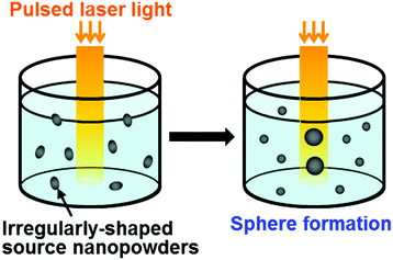
To enhance light–CaP interactions, we integrated HAp nanopowders with carbon nanopowders as a light-absorbing agent by mechanical milling prior to the pulsed laser melting in liquid process (Fig. 11a).89 The integration with carbon nanopowders as a light-absorbing agent was proposed in previous reports on the fabrication of nanospheres of optically transparent metal oxides (e.g., Al2O3, MgO, and ZrO2).90,91 The carbon-integrated HAp nanopowders (Fig. 11b, left) were dispersed into ethanol and irradiated with a weak pulsed laser light (λ = 355 nm, 8 mm diameter circle) without focusing. After irradiation for 20 min, CaP nanospheres (Fig. 11b, right) with single-hollow, multi-hollow, and solid structures were obtained (Fig. 11c). During this process, the carbon nanopowders absorbed laser light energy and transferred the energy to HAp nanopowders, causing the melting and spheroidization of the carbon-integrated HAp nanopowders in the liquid solvent (ethanol). During laser irradiation, most carbon nanopowders were sublimated or degraded and were not incorporated within the final spheres. The hollows were considered to be produced when the gases produced in the nanopowders were not released before final solidification. The resulting hollow spheres would be advantageous for drug delivery applications due to their large loading capacity.
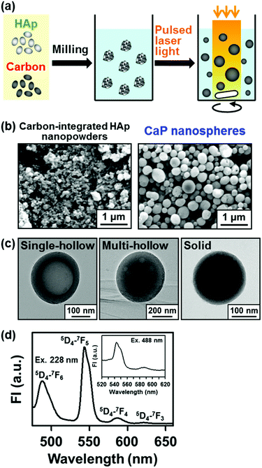 | ||
| Fig. 11 Fabrication of CaP nanospheres by the pulsed laser melting in liquid process (modified from ref. 89 with permission). (a) Schematic illustration. (b) SEM images of the carbon-integrated HAp nanopowders and the CaP nanospheres. (c) TEM images of the CaP nanospheres. (d) Fluorescence spectrum of the terbium-incorporated CaP nanospheres dispersed in ultrapure water with excitation at 228 nm and 488 nm (inset). | ||
In the carbon-assisted pulsed laser melting in liquid process, it is possible to incorporate additional functional ions into the nanospheres via ion adsorption onto the spheres followed by melt diffusion under irradiation. We produced CaP nanospheres with fluorescence by adding terbium ions to the dispersed solution of carbon-integrated HAp nanopowders prior to the pulsed laser melting in liquid process.89 A larger amount of terbium ions were incorporated into CaP nanospheres under laser irradiation than under mere stirring without irradiation due to the laser-mediated melt diffusion of terbium ions. The resulting terbium-incorporated CaP nanospheres exhibited fluorescence peaks characteristic of terbium ions (Fig. 11d). The fluorescent hollow nanospheres of terbium-incorporated CaP would be useful as multifunctional drug delivery carriers with large drug-loading capacity, good biocompatibility, pH-dependent biodegradability, and fluorescent imaging ability.
As described above, pulsed laser melting in liquid process is useful for fabricating various functional nanospheres. Due to the relatively large beam size of unfocused pulsed laser light, the mass productivity of this process was greatly improved compared with the conventional laser ablation in liquid process using focused laser light. However, for the nanosphere fabrication of low-laser-absorbing materials such as CaPs, a prior integration step (mechanical milling) with light-absorbing agents (e.g., carbon nanopowders) was required. In addition, size-regulated CaP nanopowders and carbon nanopowders must be prepared or purchased separately; these nanomaterials in the powder form are generally difficult to handle, and their production cost is relatively high. Rather than powder–powder physical integration, chemical coprecipitation in a labile supersaturated CaP solution would be a much easier way to integrate light-absorbing agents with CaPs. In the following sections, we review our new physicochemical technique for the fabrication of CaP-based spheres using liquid (ion) sources instead of nanopowders, which is based on laser processing in labile supersaturated CaP solutions.
3.3 Fabrication of CaP nanospheres via laser processing in labile supersaturated CaP solutions
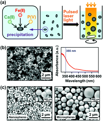 | ||
| Fig. 12 Physicochemical fabrication of iron-incorporated CaP nanospheres and microspheres using ferrous ions as a light-absorbing agent (modified from ref. 44 with permission). (a) Schematic illustration. (b) SEM image and absorption spectrum of the iron-incorporated CaP nanoprecipitates formed by mixing three ion source solutions prior to laser irradiation. (c) SEM images and magnified SEM images (insets) of the iron-incorporated CaP nanospheres and microspheres. | ||
The laser irradiation conditions (laser fluence, irradiation time, and wavelength) and the ferric/ferrous ion concentrations in the CaP solution had a critical influence on sphere formation and size (Table 1) along with sphere yield and chemical composition. For example, sphere formation and growth were enhanced with increasing laser fluence from 67 mJ per pulse per cm2 (no sphere formation) to 133 mJ per pulse per cm2 (nanosphere formation) and 200 mJ per pulse per cm2 (both nanosphere and microsphere formation) for the same irradiation time (30 min) and ferric/ferrous ion concentrations (5.0 mM) (Table 1a). Under laser irradiation at 200 mJ per pulse per cm2, CaP-based nanospheres appeared within 10 min and grew into microspheres within 15–20 min (Table 1b). As shown in Table 1c, at least 2.0 mM ferric or ferrous ions were necessary for nanosphere formation under laser irradiation at 200 mJ per pulse per cm2 for 30 min. In the process using ferric ions, sphere formation and growth were enhanced most at the ferric ion concentration of 5.0 mM (both nanosphere and microsphere were formed). At higher ferric ion concentration, sphere formation was inhibited; only nanospheres (no microspheres) were obtained at 7.0 mM, and spheres were scarcely obtained at 10.0 mM. This might be due to the acidic property of the ferric ion source, FeCl3, which lowers the solution pH and is thus unfavorable for CaP nucleation and growth.92 In contrast, in the process using ferrous ions, both nanospheres and microspheres were obtained in a wider range of ferrous ion concentrations (5.0, 10.0, and 20.0 mM) because the ferrous ion source, FeCl2, has less of an acidifying effect than FeCl3. It should be noted that the iron content in the spheres increased with increasing ferric/ferrous ion concentrations in the CaP solution. These results suggest that the sizes and chemical compositions of the spheres are controllable by tuning the experimental conditions. The amounts of the spheres obtained by the process using ferric and ferrous ions (5 mM) are estimated to be around 0.6 and 1.4 mg, respectively, per batch (4 mL reaction mixture), considering the contents of calcium, phosphorus, and iron in the spheres.44
| (a) Effect of laser fluence (30 min, Fe3+ or Fe2+: 5 mM) | |||
|---|---|---|---|
| (mJ per pulse per cm2) | 67 | 133 | 200 |
| a Data not obtained. | |||
| Fe3+ | I | N | N + M |
| Fe2+ | I | N | N + M |
| (b) Effect of irradiation time (200 mJ per pulse per cm2, Fe3+ or Fe2+: 5 mM) | ||||||
|---|---|---|---|---|---|---|
| (min) | 0 | 5 | 10 | 15 | 20 | 30 |
| Fe3+ | I | I | N | N | N + M | N + M |
| Fe2+ | I | I | N | N + M | N + M | N + M |
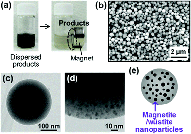 | ||
| Fig. 13 CaP-based magnetic nanospheres (modified from ref. 44 with permission). (a) Digital images of the magnetic products dispersed in ultrapure water. (b–e) SEM (b), TEM (c), magnified TEM (d), and illustrated (e) images of the spheres. | ||
3.4 Challenges and perspective
As described above, laser processing in liquid is a promising tool for the surfactant-free fabrication of nanospheres of various materials. Nanospheres have a high potential as delivery carriers for therapeutic and diagnostic agents, because they are expected to be injectable and can penetrate into tiny interstices in a body owing to their nanosize. Moreover, they can be easily redispersed and cause minimal physical irritation to living organisms because of their spherical shape. Recently, CaP-based nanospheres were fabricated by the laser ablation in liquid process (Section 3.2.1) and the carbon-assisted pulsed laser melting in liquid process (Section 3.2.2) using solid CaP sources. More recently, CaP-based nanospheres were fabricated by our new physicochemical process (laser processing in labile supersaturated CaP solutions) using liquid (ion) CaP sources. As described in Section 3.3, our physicochemical process is simple (one-pot) and rapid (short irradiation time). In addition, the source materials needed for this process are aqueous solutions of commonly used inorganic salts, and there is no need to use solid sources (either CaP targets or carbon-integrated CaP nanopowders) and surfactants. The chemical compositions and nanostructures of the resulting spheres are controllable by tuning the coprecipitation and irradiation conditions. Future challenges for biomedical applications include an increase in productivity (for larger scale production), in vitro and in vivo evaluation of biocompatibility, biodegradability, biological functions, and biodistribution of the spheres.According to the proposed sphere-forming mechanism of our physicochemical process (Section 3.3), other metal ions besides ferric and ferrous ions can also be used as the light-absorbing agents and incorporated into the final CaP-based spheres. Depending on the choice of metal ions as light-absorbing agents, the resulting CaP-based spheres may exhibit different and diverse biomedical functions. Therefore, our physicochemical process has great potential as a new fabrication tool for CaP-based nanospheres for medical and dental applications.
4. Conclusions
The simple and rapid fabrication of CaP-based thin layers and nanospheres has been achieved using a new physicochemical process: laser processing in supersaturated CaP solutions, which combines a physical laser process with a chemical precipitation process. Depending on the coprecipitation and irradiation conditions, the resulting CaP-based thin layers and nanospheres exhibited a variety of physicochemical and biological properties. The developed physicochemical process has great potential as a new fabrication tool for CaP-based thin layers and nanospheres for biomedical applications.Acknowledgements
Part of our research was supported by JSPS KAKENHI Grant Numbers JP16H03831, JP25108517 and JP15H00906, Japan, the Magnetic Health Science Foundation, Japan, and the Amada Foundation, Japan. We thank Ms Ikuko Sakamaki, Dr Yoshiki Shimizu, Dr Kenji Koga, Dr Yoshie Ishikawa, Dr Alexander Pyatenko, Dr Atsuo Ito and Dr Moumita Mahanti from AIST, Ms Nao Matsuoka and Dr Hidero Unuma from Yamagata university, and Dr Naoto Koshizaki from Hokkaido university for their contributions to our research.References
- S. V. Dorozhkin, Acta Biomater., 2010, 6, 715–734 CrossRef CAS PubMed.
- E. Boanini, M. Gazzano and A. Bigi, Acta Biomater., 2010, 6, 1882–1894 CrossRef CAS PubMed.
- V. Uskoković and D. P. Uskoković, J. Biomed. Mater. Res., Part B, 2011, 96, 152–191 CrossRef PubMed.
- K. Fox, P. A. Tran and N. Tran, ChemPhysChem, 2012, 13, 2495–2506 CrossRef CAS PubMed.
- M. Okada and T. Furuzono, Sci. Technol. Adv. Mater., 2012, 13, 064103 CrossRef.
- M. Sadat-Shojai, M. T. Khorasani, E. Dinpanah-Khoshdargi and A. Jamshidi, Acta Biomater., 2013, 9, 7591–7621 CrossRef CAS PubMed.
- K. Lin, C. Wu and J. Chang, Acta Biomater., 2014, 10, 4071–4102 CrossRef CAS PubMed.
- S. V. Dorozhkin, Ceram. Int., 2015, 41, 13913–13966 CrossRef CAS.
- Z. Sheikh, M. N. Abdallah, A. A. Hanafi, S. Misbahuddin, H. Rashid and M. Glogauer, Materials, 2015, 8, 7913–7925 CrossRef.
- S. V. Dorozhkin, Mater. Sci. Eng., C, 2015, 55, 272–326 CrossRef CAS PubMed.
- W. Habraken, P. Habibovic, M. Epple and M. Bohner, Mater. Today, 2016, 19, 69–87 CrossRef CAS.
- O. Suzuki, Acta Biomater., 2010, 6, 3379–3387 CrossRef CAS PubMed.
- S. V. Dorozhkin, Int. J. Mater. Chem., 2012, 2, 19–46 CrossRef CAS.
- D. Tadic and M. Epple, Biomaterials, 2004, 25, 987–994 CrossRef CAS PubMed.
- J. Zhang, W. Liu, V. Schnitzler, F. Tancret and J. M. Bouler, Acta Biomater., 2014, 10, 1035–1049 CrossRef CAS PubMed.
- J. H. Shepherd, D. V. Shepherd and S. M. Best, J. Mater. Sci.: Mater. Med., 2012, 23, 2335–2347 CrossRef CAS PubMed.
- J. Kolmas, E. Groszyk and D. Kwiatkowska-Różycka, BioMed Res. Int., 2014, 2014, 178123 Search PubMed.
- M. Šupová, Ceram. Int., 2015, 41, 9203–9231 CrossRef.
- L. J. Cummings, M. A. Snyder and K. Brisack, Methods Enzymol., 2009, 463, 387–404 CAS.
- R. Freitag and F. Hilbrig, Biotechnol. J., 2012, 7, 90–102 CrossRef PubMed.
- M. Vila, S. Sánchez-Salcedo and M. Vallet-Regí, Inorg. Chim. Acta, 2012, 393, 24–35 CrossRef CAS.
- P. Chand and Y. B. Pakade, Environ. Sci. Pollut. Res., 2015, 22, 10919–10929 CrossRef CAS PubMed.
- K. Khosravi-Darani, M. R. Mozafari, L. Rashidi and M. Mohammadi, Acta Med. Iran., 2010, 48, 133–141 CAS.
- D. Lee, K. Upadhye and P. N. Kumta, Mater. Sci. Eng., B, 2012, 177, 289–302 CrossRef CAS.
- A. Oyane, X. Wang, Y. Sogo, A. Ito and H. Tsurushima, Acta Biomater., 2012, 8, 2034–2046 CrossRef CAS PubMed.
- M. Zhang and K. Kataoka, Nano Today, 2009, 4, 508–517 CrossRef CAS.
- M. Epple, K. Ganesan, R. Heumann, J. Klesing, A. Kovtun, S. Neumann and V. Sokolova, J. Mater. Chem., 2010, 20, 18–23 RSC.
- S. S. Syamchand and G. Sony, Microchim. Acta, 2015, 182, 1567–1589 CrossRef CAS.
- S. C. G. Leeuwenburgh, J. G. C. Wolke, J. A. Jansen and K. de Groot, in Bioceramics and their clinical applications, ed. T. Kokubo, Woodhead Pub., Cambridge, England, 2008, vol. 20, pp. 464–484 Search PubMed.
- R. A. Surmenev, M. A. Surmeneva and A. A. Ivanova, Acta Biomater., 2014, 10, 557–579 CrossRef CAS PubMed.
- S. R. Paital and N. B. Dahotre, Mater. Sci. Eng., R, 2009, 66, 1–70 CrossRef.
- R. A. Surmenev, Surf. Coat. Technol., 2012, 206, 2035–2056 CrossRef CAS.
- S. Shadanbaz and G. J. Dias, Acta Biomater., 2012, 8, 20–30 CrossRef CAS PubMed.
- Y. H. Liang, C. H. Liu, S. H. Liao, Y. Y. Lin, H. W. Tang, S. Y. Liu, I. R. Lai and K. C. W. Wu, ACS Appl. Mater. Interfaces, 2012, 4, 6720–6727 CAS.
- B. P. Bastakoti, M. Inuoe, S. Yusa, S. H. Liao, K. C. W. Wu, K. Nakashima and Y. Yamauchi, Chem. Commun., 2012, 48, 6532–6534 RSC.
- B. P. Bastakoti, Y. C. Hsu, S. H. Liao, K. C. W. Wu, M. Inoue, S. Yusa, K. Nakashima and Y. Yamauchi, Chem. – Asian J., 2013, 8, 1301–1305 CrossRef CAS PubMed.
- Y. H. Yang, C. H. Liu, Y. H. Liang, F. H. Lin and K. C. W. Wu, J. Mater. Chem. B, 2013, 1, 2447–2450 RSC.
- A. Oyane, I. Sakamaki, Y. Shimizu, K. Kawaguchi and N. Koshizaki, J. Biomed. Mater. Res., Part A, 2012, 100, 2573–2580 CrossRef PubMed.
- A. Oyane, I. Sakamaki, Y. Shimizu, K. Kawaguchi, Y. Sogo, A. Ito and N. Koshizaki, Key Eng. Mater., 2013, 529–530, 217–222 CAS.
- A. Oyane, I. Sakamaki, A. Pyatenko, M. Nakamura, Y. Ishikawa, Y. Shimizu, K. Kawaguchi and N. Koshizaki, RSC Adv., 2014, 4, 53645–53648 RSC.
- A. Oyane, N. Matsuoka, K. Koga, Y. Shimizu, M. Nakamura, K. Kawaguchi, N. Koshizaki, Y. Sogo, A. Ito and H. Unuma, Colloids Interface Sci. Commun., 2015, 4, 5–9 CrossRef CAS.
- M. Mahanti, M. Nakamura, A. Pyatenko, I. Sakamaki, K. Koga and A. Oyane, J. Phys. D: Appl. Phys., 2016, 49, 304003 CrossRef.
- M. Nakamura, A. Oyane, I. Sakamaki, Y. Ishikawa, Y. Shimizu, K. Koga, K. Kawaguchi and N. Koshizaki, RSC Adv., 2014, 4, 38442–38445 RSC.
- M. Nakamura, A. Oyane, I. Sakamaki, Y. Ishikawa, Y. Shimizu and K. Kawaguchi, Phys. Chem. Chem. Phys., 2015, 17, 8836–8842 RSC.
- Y. Liu, G. Wu and K. de Groot, J. R. Soc., Interface, 2010, 7, S631–S647 CrossRef CAS PubMed.
- X. Wang, A. Ito, X. Li, Y. Sogo and A. Oyane, Biofabrication, 2011, 3, 022001 CrossRef PubMed.
- X. Wang, A. Oyane and A. Ito, in Advances in calcium phosphate biomaterials, ed. B. Ben-Nissan, Springer-Verlag, Berlin Heidelberg, Germany, 2014, vol. 2, pp. 171–197 Search PubMed.
- T. Kokubo and H. Takadama, Biomaterials, 2006, 27, 2907–2915 CrossRef CAS PubMed.
- A. C. Tas, Acta Biomater., 2014, 10, 1771–1792 CrossRef CAS PubMed.
- L. Pramatarova, E. Pecheva, T. Petrov, A. Kondyurin, R. Pramatarova and N. Minkovski, Vacuum, 2004, 76, 339–342 CrossRef CAS.
- L. Pramatarova, E. Pecheva, D. Dimova-Malinovska, R. Pramatarova, U. Bismayer, T. Petrov and N. Minkovski, Vacuum, 2004, 76, 135–138 CrossRef CAS.
- L. Pramatarova, E. Pecheva, R. Presker, M. T. Pham, M. F. Maitz and M. Stutzmann, Eur. Cells Mater., 2005, 9, 9–12 CAS.
- E. Pecheva, T. Petrov, C. Lungu, P. Montgomery and L. Pramatarova, Chem. Eng. J., 2008, 137, 144–153 CrossRef CAS.
- B. H. Lee, A. Oyane, H. Tsurushima, Y. Shimizu, T. Sasaki and N. Koshizaki, ACS Appl. Mater. Interfaces, 2009, 1, 1520–1524 CAS.
- T. Kasuga, H. Kondo and M. Nogami, J. Cryst. Growth, 2002, 235, 235–240 CrossRef CAS.
- X. Liu, X. Zhao, B. Li, C. Cao, Y. Dong, C. Ding and P. K. Chu, Acta Biomater., 2008, 4, 544–552 CrossRef CAS PubMed.
- A. Guha, S. Nayar and H. N. Thatoi, Bioinspiration Biomimetics, 2010, 5, 024001 CrossRef PubMed.
- H. Zhou, M. Nabiyouni and S. B. Bhaduri, Mater. Sci. Eng., C, 2013, 33, 4435–4443 CrossRef CAS PubMed.
- H. Zhou, V. K. Goel and S. B. Bhaduri, Mater. Lett., 2014, 125, 96–98 CrossRef CAS.
- Y. Ren, H. Zhou, M. Nabiyouni and S. B. Bhaduri, Mater. Sci. Eng., C, 2015, 49, 364–372 CrossRef CAS PubMed.
- M. Uchida, A. Oyane, H. M. Kim, T. Kokubo and A. Ito, Adv. Mater., 2004, 16, 1071–1074 CrossRef CAS.
- H. McDowell, T. M. Gregory and W. E. Brown, J. Res. Natl. Bur. Stand., Sect. A, 1977, 81, 273–281 CrossRef.
- M. R. Christoffersen, J. Christoffersen and W. Kibalczyc, J. Cryst. Growth, 1990, 106, 349–354 CrossRef CAS.
- A. Ito, H. Kawamura, M. Otsuka, M. Ikeuchi, H. Ohgushi, K. Ishikawa, K. Onuma, N. Kanzaki, Y. Sogo and N. Ichinose, Mater. Sci. Eng., C, 2002, 22, 21–25 CrossRef.
- Y. Sogo, A. Ito, T. Matsuno, A. Oyane, G. Tamazawa, T. Satoh, A. Yamazaki, E. Uchimura and T. Ohno, Biomed. Mater., 2007, 2, 116–123 CrossRef CAS PubMed.
- X. Wang, A. Ito, Y. Sogo, X. Li and A. Oyane, Acta Biomater., 2010, 6, 962–968 CrossRef CAS PubMed.
- C. de Paula Eduardo, P. M. de Freitas, M. Esteves-Oliveira, A. C. C. Aranha, K. M. Ramalho, A. Simões, M. S. Bello-Silva and J. Tunér, Lasers Med. Sci., 2010, 25, 781–792 CrossRef PubMed.
- S. K. Houston, C. C. Wykoff, A. M. Berrocal, D. J. Hess and T. G. Murray, Lasers Med. Sci., 2013, 28, 1025–1034 CrossRef PubMed.
- K. França, A. Chacon, J. Ledon, J. Savas, J. Izakovic and K. Nouri, Lasers Med. Sci., 2013, 28, 1197–1204 CrossRef PubMed.
- P. M. S. L. Shanthi, R. V. Mangalaraja, A. P. Uthirakumar, S. Velmathi, T. Balasubramanian and M. Ashok, J. Colloid Interface Sci., 2010, 350, 39–43 CrossRef CAS PubMed.
- F. Ye, H. Guo, H. Zhang and X. He, Acta Biomater., 2010, 6, 2212–2218 CrossRef CAS PubMed.
- H. Zhou and S. Bhaduri, J. Biomed. Mater. Res., Part B, 2012, 100, 1142–1150 CrossRef PubMed.
- C. Qi, Y. J. Zhu, X. Y. Zhao, B. Q. Lu, Q. L. Tang, J. Zhao and F. Chen, Chem. – Eur. J., 2013, 19, 981–987 CrossRef CAS PubMed.
- J. Zhao, Y. J. Zhu, J. Q. Zheng, F. Chen and J. Wu, Microporous Mesoporous Mater., 2013, 180, 79–85 CrossRef CAS.
- P. Rouhani, N. Taghavinia and S. Rouhani, Ultrason. Sonochem., 2010, 17, 853–856 CrossRef CAS PubMed.
- A. Fojtik and A. Henglein, Ber. Bunsen-Ges. Phys. Chem., 1993, 97, 252–254 CrossRef CAS.
- G. Yang, Prog. Mater. Sci., 2007, 52, 648–698 CrossRef CAS.
- V. Amendola and M. Meneghetti, Phys. Chem. Chem. Phys., 2009, 11, 3805–3821 RSC.
- H. Zeng, X. W. Du, S. C. Singh, S. A. Kulinich, S. Yang, J. He and W. Cai, Adv. Funct. Mater., 2012, 22, 1333–1353 CrossRef CAS.
- S. W. Mhin, J. H. Ryu, K. M. Kim, G. S. Park, H. W. Ryu, K. B. Shim, T. Sasaki and N. Koshizaki, Appl. Phys. A: Mater. Sci. Process., 2009, 96, 435–440 CrossRef CAS.
- M. Boutinguiza, J. Pou, F. Lusquiños, R. Comesaña and A. Riveiro, Appl. Surf. Sci., 2011, 257, 5195–5199 CrossRef CAS.
- M. Boutinguiza, J. Pou, F. Lusquiños, R. Comesaña and A. Riveiro, Phys. Procedia, 2011, 12, 54–59 CrossRef CAS.
- H. Wang, A. Pyatenko, K. Kawaguchi, X. Li, Z. Swiatkowska-Warkocka and N. Koshizaki, Angew. Chem., Int. Ed., 2010, 49, 6361–6364 CrossRef CAS PubMed.
- Y. Ishikawa, Y. Shimizu, T. Sasaki and N. Koshizaki, Appl. Phys. Lett., 2007, 91, 161110 CrossRef.
- H. Wang, N. Koshizaki, L. Li, L. Jia, K. Kawaguchi, X. Li, A. Pyatenko, Z. Swiatkowska-Warkocka, Y. Bando and D. Golberg, Adv. Mater., 2011, 23, 1865–1870 CrossRef CAS PubMed.
- X. Li, A. Pyatenko, Y. Shimizu, H. Wang, K. Koga and N. Koshizaki, Langmuir, 2011, 27, 5076–5080 CrossRef CAS PubMed.
- Z. Swiatkowska-Warkocka, K. Koga, K. Kawaguchi, H. Wang, A. Pyatenko and N. Koshizaki, RSC Adv., 2013, 3, 79–83 RSC.
- T. Tsuji, T. Yahata, M. Yasutomo, K. Igawa, M. Tsuji, Y. Ishikawa and N. Koshizaki, Phys. Chem. Chem. Phys., 2013, 15, 3099–3107 RSC.
- M. Nakamura, A. Oyane, I. Sakamaki, Y. Shimizu, K. Koga and N. Koshizaki, RSC Adv., 2015, 5, 22620–22624 RSC.
- X. Li, Y. Shimizu, A. Pyatenko, H. Wang and N. Koshizaki, J. Mater. Chem., 2011, 21, 14406–14409 RSC.
- X. Li, Y. Shimizu, A. Pyatenko, H. Wang and N. Koshizaki, Nanotechnology, 2012, 23, 115602 CrossRef PubMed.
- M. S. A. Johnsson and G. H. Nancollas, Crit. Rev. Oral Biol. Med., 1992, 3, 61–82 CAS.
- M. Mahmoudi, S. Sant, B. Wang, S. Laurent and T. Sen, Adv. Drug Delivery Rev., 2011, 63, 24–46 CrossRef CAS PubMed.
- L. H. Reddy, J. L. Arias, J. Nicolas and P. Couvreur, Chem. Rev., 2012, 112, 5818–5878 CrossRef CAS PubMed.
- X. Ren, H. Chen, V. Yang and D. Sun, Front. Chem. Sci. Eng., 2014, 8, 253–264 CrossRef CAS.
- L. Dong, Z. Zhu, Y. Qiu and J. Zhao, Chem. Eng. J., 2010, 165, 827–834 CrossRef CAS.
- Y. Liu, H. Zhong, L. Li and C. Zhang, Mater. Res. Bull., 2010, 45, 2036–2039 CrossRef CAS.
- H. Yang, S. Masse, H. Zhang, C. Helary, L. Li and T. Coradin, J. Colloid Interface Sci., 2014, 417, 1–8 CrossRef CAS PubMed.
- H. C. Wu, T. W. Wang, J. S. Sun, W. H. Wang and F. H. Lin, Nanotechnology, 2007, 18, 165601 CrossRef.
- E. B. Ansar, M. Ajeesh, Y. Yokogawa, W. Wunderlich and H. Varma, J. Am. Ceram. Soc., 2012, 95, 2695–2699 CrossRef CAS.
| This journal is © The Royal Society of Chemistry 2016 |

