
 Open Access Article
 This Open Access Article is licensed under a Creative Commons Attribution-Non Commercial 3.0 Unported Licence
An electropolymerized molecularly imprinted polymer for selective carnosine sensing with impedimetric capacity†
Agnieszka
Wojnarowicz
a,
Piyush Sindhu
Sharma
*a,
Marta
Sosnowska
ab,
Wojciech
Lisowski
a,
Tan-Phat
Huynh
ab,
Maria
Pszona
a,
Paweł
Borowicz
ac,
Francis
D'Souza
*b and
Wlodzimierz
Kutner
*ad
aInstitute of Physical Chemistry (IPC PAS), Kasprzaka 44/52, 01-224 Warsaw, Poland. E-mail: psharma@ichf.edu.pl; wkutner@ichf.edu.pl
bDepartment of Chemistry, University of North Texas, 1155, Union Circle, #305070, Denton, TX 76203-5017, USA. E-mail: Francis.Dsouza@unt.edu
cInstitute of Electron Technology, Al. Lotnikow 37/46, 02-668 Warsaw, Poland
dFaculty of Mathematics and Natural Sciences, School of Sciences, Cardinal Stefan Wyszynski University in Warsaw, Woycickiego 1/3, 01-938 Warsaw, Poland
First published on 4th January 2016
Abstract
A chemosensor with a molecularly imprinted polymer (MIP) film as the recognition unit selective to a carnosine biomarker was molecularly engineered, devised and fabricated. The molecular structure of the pre-polymerization complex of the carnosine template with the carboxy and 18-crown-6 ether derivatives of bis(2,2′-bithien-5-yl)methane functional monomers was thermodynamically optimized by density functional theory (DFT) at the B3LYP/6-31g(d) level. The calculated high negative Gibbs free energy change, ΔG = −227.4 kJ mol−1, indicated the formation of a very stable complex. The solution of this complex was prepared and used for deposition of the MIP films on a Pt disk electrode or an Au electrode of the quartz crystal resonator by potentiodynamic electropolymerization. Subsequently, the carnosine template was extracted from the MIPs with 0.1 M NaOH, as confirmed by the differential pulse voltammetry (DPV), X-ray photoelectron spectroscopy (XPS), and Raman spectroscopy measurements. For carnosine sensing, impedimetric capacity (IC) measurements were performed under flow-injection analysis (FIA) conditions resulting in the limit of detection of 20 μM (at S/N = 3). This limit implied the readiness of the chemosensor for carnosine determination in clinical samples. Due to multiple modes of carnosine binding to MIP recognition sites, the IC chemosensor was found to be more selective to carnosine than to its common interferences including anserine, carcinine and histidine. Advantageously, the imprinting factor, determined by piezoelectric microgravimetry (PM), was high equaling 14.9.
Introduction
Carnosine 1 (Scheme 1a) is a dipeptide composed of L-histidine and β-alanine. Carnosine, L-anserine, and hemocarnosine are three representative histidine-containing dipeptides widely distributed in the human body. There, carnosine is synthesized by the ATP-dependent carnosine synthetase enzyme.1,2 The highest carnosine concentrations are found in the skeletal muscle tissues, stomach, kidney, and cardiac muscles,3–6 as well as in brain neurons, olfactory bulbs, and glial cells.7–9 Carnosine plays several important roles in human body. First, it is a chelator of metal ions including copper, zinc, and iron.10,11 Second, its buffering activity helps control the intracellular hydrogen ion concentration.12,13 Moreover, carnosine is known as an antioxidant,14–17 anti-glycating agent,18–20 and hydroxyl radical scavenger.21 Therefore, it is administered as a potential supplement of diet or medicine in treatment of many diseases including diabetes,22 vascular dementia,12 neurological disorders (e.g., Alzheimer's disease23 and Parkinson's disease24) as well as in ocular diseases, e.g., cataract25 and diabetic retinopathy.26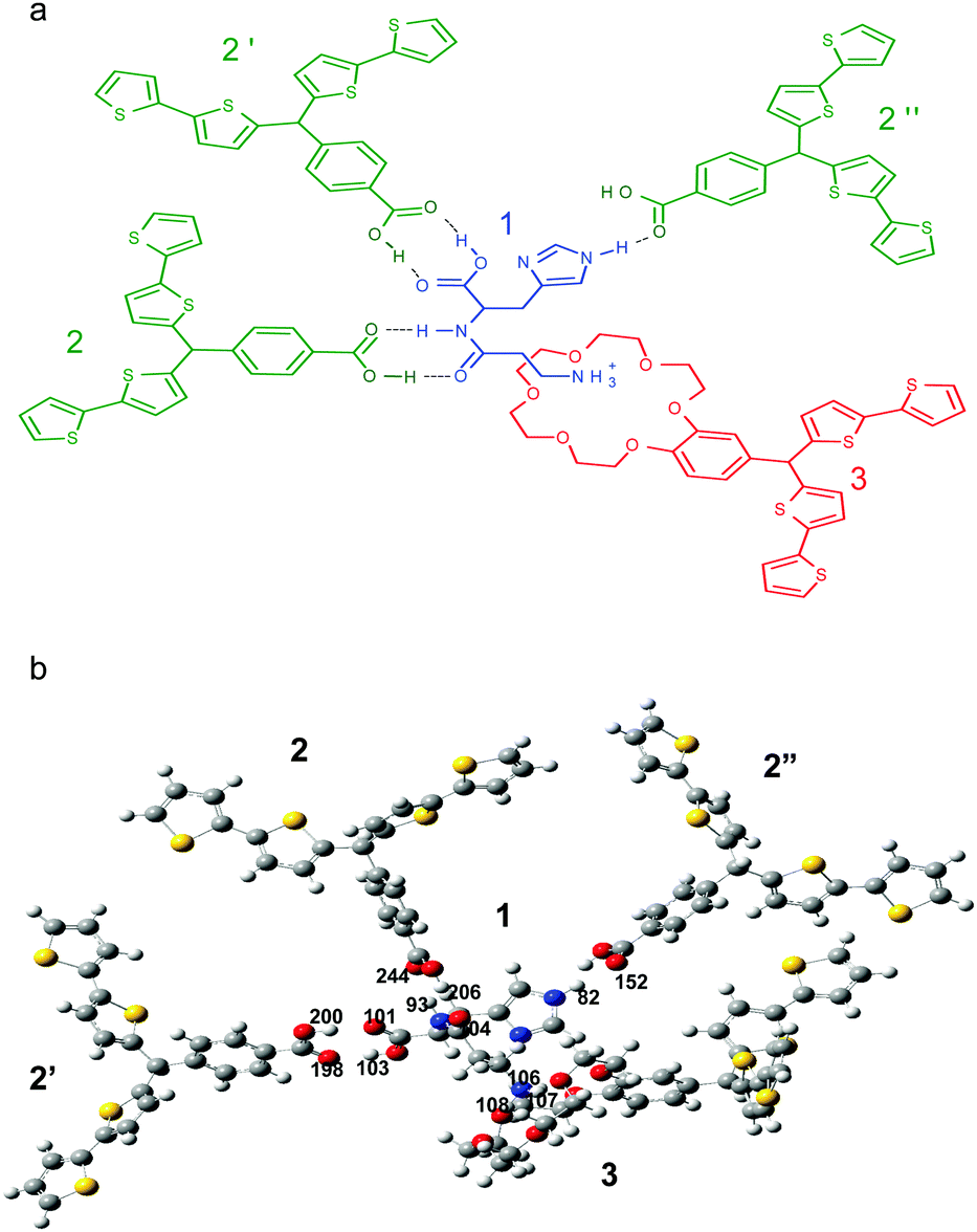 | ||
| Scheme 1 (a) The proposed structural formula of the pre-polymerization complex of the carnosine template 1 with functional monomers 2 and 3, and (b) the B3LYP/6-31g(d) optimized structure of the complex. Gray, red, blue, yellow, and white spheres represent carbon, oxygen, nitrogen, sulfur, and hydrogen atoms, respectively. | ||
Carnosine is used as a biomarker, i.e., a biological molecule occurring in body fluids or tissues whose concentration, 18.6 ± 16.8 μM in urine27 and 20–180 mg carnosine/(100 g wet weight skeletal muscle tissue),28 reflects the conditions of processes or reactions for treatment. Carnosine level determination in serum can help indicate serum carnosinase deficiency (carnosinemia), which is an autosomal recessive metabolic disorder29–31 caused by the CNDP1 gene mutation. This disorder is manifested by the increased carnosine concentration in urine.32 Importantly, detection of carnosine can help diagnose Alzheimer's and Parkinson's diseases,1,23 as well.
For carnosine determination, mostly flow analytical techniques are used including high-performance liquid chromatography (HPLC),33,34 hydrophilic interaction liquid chromatography (HILIC),35 and capillary electrophoresis (CE).36,37 The limit of detection of carnosine reached by these techniques is high. However, all of them are expensive and require trained personnel to operate them. They are time-consuming and labor-demanding because of a long analysis time and additional necessary sample preparation steps. For instance, electrophoresis requires derivatization of carnosine prior to determination.36,37 Towards sensing of carnosine, a recent report described differential pulse voltammetry (DPV) determination of this dipeptide at the μM concentration level.38 Unfortunately, the sensor suffers from low selectivity with respect to the anserine structural analogue of carnosine. Moreover, a cross-reactive chemosensor array was developed by combining transition-metal complexes with six different fluorescent dyes for selective determination of carnosine and hemocarnosine.39 However, this chemosensor array required a specialized hardware to operate and time-consuming sample pretreatment.
The chemosensors with dedicated molecularly imprinted polymers (MIPs) as recognition units for selective and reversible interactions with carnosine are expected to overcome these determination disadvantages. Molecular imprinting is a procedure that leads to the formation of molecular cavities in a polymer matrix with a memory of the size, shape, and orientation of the template molecules used for imprinting. Often, an analyte itself initially serves as the template.40 Therefore, the MIP use for chemosensor fabrication has been increasing for the last few decades.41–43 Mostly, MIPs were prepared by free-radical polymerization of vinyl or acrylic functional monomers derivatized with recognition sites.44 However, literature on the MIP application for carnosine determination is scarce.45 The polymer imprinted with carnosine suffered from a long-time preparation procedure and it was not used as a recognition unit of a chemosensor.45
In the present study, we used carnosine-templated MIPs as recognition units of carnosine chemical sensors. For the imprinting, we utilized bis(2,2′-bithiophene) derived functional monomers developed in our laboratories due to their availability with a variety of recognition sites.46 The monomers used in the present study are composed of two parts. One part is an electroactive bis(2,2′-bithiophene) moiety capable of electropolymerization while the other is a recognition site capable of interacting with the available binding sites of the carnosine template.47 Advantageously, the thickness and morphology of the bis(2,2′-bithiophene) based MIPs prepared by electropolymerization are easily controlled.48–50 Moreover, this electropolymerization does not require using any initiator and, additionally, chemical stability of the resulting MIPs is high. Accordingly, two functional monomers were chosen, namely, 4-bis(2,2′-bithien-5-yl)methylbenzoic acid 2 and bis(2,2-bithienyl)benzo[18-crown-6]methane 3 (Scheme 1). The structure of the pre-polymerization complex of the functional monomers and the carnosine template was optimized with quantum chemistry computing. A mixture of solvents was carefully composed to dissolve all components of the pre-polymerization complex, and then to enable electropolymerization of this complex. The MIP films were deposited on two different signal transducers. These included a Pt disk electrode for impedimetric capacity (IC) measurements by impedimetry and an Au film coated quartz crystal resonator (Au-QCR) for piezoelectric microgravimetry (PM). Moreover, these films were deposited on the Au film coated glass slides for spectroscopic analyses and microscopic imaging. Subsequent extraction of the carnosine template from the MIP films resulted in the fabrication of recognition units of the chemosensor.
Experimental
Reagents and chemicals
L-Carnosine 1 (Scheme 1a), L-anserine nitrate salt, L-histidine, carcinine dihydrochloride, and acetonitrile “for electrochemistry” were purchased from Sigma-Aldrich. Tetrabutylammonium perchlorate, (TBA)ClO4, was from Fluka. Lithium nitrate was provided by CIECH S.A. Sodium hydroxide, potassium nitrate, and potassium hexacyanoferrate(II) were purchased from POCH S.A. Functional monomers 2 and 3 (Scheme 1a) were prepared, as described previously.49,51Instrumentation and procedures
The electropolymerization under potentiodynamic conditions, cyclic voltammetry (CV), and differential pulse voltammetry (DPV) measurements were performed using an SP-300 BioLogic potentiostat controlled by the EC-Lab BioLogic software. A 1 mm diameter Pt disk electrode, a 5 mm diameter gold film electrode deposited on an Au-QCR, and a glass slide coated with Au films were used as the working electrodes. A Pt wire and an Ag/AgCl electrode were used as the counter and reference electrode, respectively.Extraction of the carnosine template from the MIP films was controlled by DPV in the potential range of 0.0 to 0.60 V. For that purpose, the 0.1 M K4Fe(CN)6 redox probe in 0.1 M KNO3 was used.
Before and after carnosine template extraction, the deposited MIP film was imaged by atomic force microscopy (AFM) using a Nanoscope V microscope controlled by a MultiMode® 8 controller of Brucker. The TappingMode™ was used for this imaging, which embraced the (0.5 × 0.5) μm2 area. For this imaging, the MIP films were deposited on the Au film coated glass slides. These slides were cleaned with toluene, and then with acetone before deposition of the MIP films.
The X-ray photoelectron spectra (XPS) were recorded on a PHI 5000 VersaProbe™ (ULVC-PHI) scanning ESCA microprobe using monochromatic Al Kα radiation (hν = 1486.4 eV). The XPS data were generated by a 100 μm diameter X-ray beam and collected from the 250 μm2 irradiated area. The high-resolution (HR) XPS spectra were collected using a hemispherical analyzer at the pass energy of 23.5 eV, energy step of 0.1 eV, and photoelectron take off angle of 45° with respect to the surface plane. The CasaXPS software was used to evaluate the XPS data. The background was subtracted using the Shirley method and peaks were fitted using the mixed Gaussian–Lorentzian peak shape with 30% Lorentzian character. The binding energy of the Au 4f7/2 peak (BE = 84.0 eV) was chosen as the internal reference. The samples for XPS and Raman spectroscopic measurements were prepared in the same way as that used for imaging by AFM.
The Raman spectra were obtained using the InVia confocal Renishaw system using a Leica microscope with the Peltier-cooled 1024 × 256 pixel CCD detector. Signals were collected using a 100× Leica air objective (NA = 0.85) and dispersed by a 1200 grooves per mm grating. The spectral resolution was 5–6 cm−1 and the wavelength accuracy was 2 cm−1. The excitation source was the He–Ne laser (623.8 nm) and the total number of scans for each spectrum was 600. The laser power was 50–500 μW on the sample. The spectra were background corrected using cubic-spline interpolation. The experimental Raman spectra were compared with the theoretical spectra. The theoretical spectra were calculated for 3 and the complex of 1 and 3 using density functional theory (DFT) at the B3LYP/6-31G level with the harmonic approximation, using Gaussian 09 software.52 The analysis of theoretical spectra was performed using Vibrational Energy Distribution Analysis (VEDA).53,54 The background was subtracted and spectra were mathematically reconstructed using the Opus 6.5 and Fityk 0.9.8 software, respectively.55 The theoretical and experimental spectra were compared using the SPESCA software using weighted linear regression.56
The FTIR absorption spectra of carnosine template 1, functional monomer 3, and the complex of 1 with 3 in potassium bromide (KBr) pellets were recorded using a Vertex 80 V Fourier Transform Infrared (FTIR) spectrometer of Bruker with the DTGS detector. The samples were prepared by mixing 1, functional monomer 3, and the complex of 1 and 3 (the mixture of 1 and 3 was dissolved in acetonitrile![[thin space (1/6-em)]](https://www.rsc.org/images/entities/char_2009.gif) :water solution and the solvent was allowed to evaporate, thus yielding a powder) with KBr powder, respectively, and pressed to form pellets. Then, 256 scans of the FTIR spectra were recorded at 0.6 cm−1 resolution. For comparison, theoretical IR spectra were calculated using the same method as that mentioned above for calculation of theoretical Raman spectra.
:water solution and the solvent was allowed to evaporate, thus yielding a powder) with KBr powder, respectively, and pressed to form pellets. Then, 256 scans of the FTIR spectra were recorded at 0.6 cm−1 resolution. For comparison, theoretical IR spectra were calculated using the same method as that mentioned above for calculation of theoretical Raman spectra.
The PM measurements were carried out under flow-injection analysis (FIA) and stagnant-solution conditions using a flow cell57 and an EQCM 571058 quartz crystal microbalance (QCM) operated by an EQCM 5710-S2 software, respectively, and an EP-20A potentiostat, all from the Institute of Physical Chemistry PAS. The resonance frequency was measured with 0.1 Hz resolution using 14 mm diameter AT-cut plano–plano 10 MHz resonance frequency Au-QCRs with ∼100 μm thick 5 mm diameter Au film electrodes evaporated over the Ti underlayers on both sides of the resonator. However, the test solution wetted only one side of the crystal. In FIA measurements, the flow cell was connected to a 922 model Quartz Crystal Analyzer of Seiko EG&G and an SP-300 potentiostat of BioLogic, both controlled by the EC-Lab BioLogic software. A 0.1 M LiNO3 solution, used as the carrier liquid in FIA, was pumped with the flow rate of 35 μL min−1 through the flow cell using a model 78/100 syringe pump of KD Scientific. The 100 μL samples were injected using a 7725i model rotary six-port valve of Rheodyne. The carnosine analyte or its interferences were dissolved in the solution of the same composition as that of the carrier solution.
The IC measurements were performed under the same FIA conditions as those adopted for the PM measurements. The IC measurements were carried out using a large-volume (35 mL) radial-flow thin-layer electrochemical cell59 filled with the 0.1 M LiNO3 carrier solution. The Pt working electrode was axially mounted above the inlet capillary orifice at the (capillary outlet)-to-electrode distance of 300 μm. A Pt wire loop and an Ag/AgCl electrode were used as the auxiliary and reference electrode, respectively. The applied frequency and potential were kept constant at 20 Hz and 0.50 V vs. Ag/AgCl, respectively.
Polymer film preparation
The MIP film was deposited from the pre-polymerization complex solution of carnosine and functional monomers by electropolymerization under potentiodynamic conditions. This solution contained acetonitrile and water in the volume ratio of 9:1. Moreover, it was 0.1 mM in carnosine, 0.3 mM in 2, 0.1 mM in 3 and 0.1 M in the (TBA)ClO4 supporting electrolyte. Electropolymerization was carried out over the potential range of 0 to 1.40 V vs. Ag/AgCl using the Pt disk electrode, the Au-QCRs, and the Au film coated glass slides at the scan rate of 50 mV s−1. The thickness of the deposited polymer film was controlled by the number of potential cycles, and the optimum thickness60 was reached within five cycles. After the electropolymerization was completed, the electrode coated with the MIP-carnosine film was rinsed with abundant acetonitrile to remove excess of the supporting electrolyte. Then, the carnosine template was removed from the film by extraction with 0.1 M NaOH for 30 min at room temperature. Completion of this removal was confirmed by the DPV and XPS measurements.
Moreover, a non-imprinted polymer (NIP) film was prepared as control. It was deposited under solution conditions same as those used for the MIP film deposition, however, in the absence of carnosine.
Quantum chemical calculations
The structure of the pre-polymerization complex, in vacuum, of the carnosine template 1 and both functional monomers 2 and 3 was optimized, and the values of thermodynamic functions were calculated using DFT at the B3LYP/6-31G(d) level using Gaussian 09 software.52Results and discussion
Molecular modeling of interactions between binding sites of the carnosine template and recognition sites of functional monomers
The structure of the pre-polymerization complex of the carnosine template and both functional monomers was optimized by computational modeling (Scheme 1). In Scheme 1a, the structural formula of this complex is proposed. In this complex (Scheme 1b), hydrogen atoms 106, 107, and 108 of the amine group of 1 interact with the 18-crown-6 moiety of 3. Here, the crown ether moiety of 3 plays the role of a host moiety including the –NH3+ guest moiety of 1. The hydrogen atom 103 and the oxygen atom 101 of 1 are complementarily paired with the oxygen atom 198 and the hydrogen atom 200 of the carboxy group of 2′, respectively, forming two distinct hydrogen bonds. The same interactions are characteristic of atoms of the peptide bond of 1. That is, the hydrogen atom 93 and the oxygen atom 104 of carnosine are complementarily paired with the oxygen atom 244 and the hydrogen atom 246 of 2, respectively. The hydrogen atom 82 of the imidazole substituent of 1 forms a hydrogen bond with the oxygen atom 152 of the carbonyl group of 2′′. Table 1 summarizes results of the calculated Gibbs free energy change, ΔG, due to possible interactions of different recognition sites of functional monomers with complementary binding sites of the carnosine template. Calculations of the change in thermodynamic functions corresponding to the formation of a complex of 1, 2, and 3 of 1:3:1 stoichiometry and the optimized structure, resulted in a substantial total negative change in the free energy, ΔG = −227.4 kJ mol−1 (Table 1). This relatively high ΔG gain indicated the possibility of formation of a stable (multi host)–carnosine complex. In the optimized structure of carnosine, there are seven possible binding sites. Unfortunately, one site, i.e., unprotonated nitrogen of the imidazole ring, is not accessible to any recognition site of the functional monomers because of steric hindrance. Nevertheless, the computational DFT modeling indicated, advantageously, strong six-point binding of the carnosine template.
| Functional monomer | Type of binding | ΔG (kJ mol−1) |
|---|---|---|
| Carboxylic acid derivative 2 | Hydrogen bond | −35.8 |
| Carboxylic acid derivative 2′ | Hydrogen bond | −42.8 |
| Carboxylic acid derivative 2′′ | Hydrogen bond | −22.2 |
| [18-crown-6] ether derivative 3 | Inclusion interactions | −178.2 |
| Pre-polymerization complex of the carnosine template 1 and functional monomers 2, 2′, 2′′, and 3 | −227.4 | |
The total free energy change, ΔG, because of formation of the carnosine complex was compared with the ΔG for the histidine–(functional monomers) complex where histidine was chosen as its interference because the histidine moiety is a part of the carnosine dipeptide. For that purpose, computational modeling was performed. The complex structure was “frozen” in such a way that the recognition sites of the functional monomers were left “unfrozen”.46 After that, carnosine and histidine molecules were allowed to equilibrate, separately, with the “frozen” molecular cavity. The total free energy change for the “frozen” carnosine complex was −347.01 kJ mol−1. However, this change for the “frozen” histidine complex was nearly half, ΔG = −183.85 kJ mol−1. These results confirmed that the designed molecular cavity of the MIP preferentially bound the carnosine dipeptide molecule.
Infrared spectroscopic characterization of pre-polymerization complex formation in solution
Several studies confirmed that oxygen atoms of crown ethers interact with hydrogen atoms of protonated primary and secondary amines.61–65 In effect, inclusion complexes are formed. We performed IR measurements to verify host–guest interactions between the carnosine template 1 and the 18-crown-6 derivatized bisbithiophene functional monomer 3. Accordingly, in Fig. S1 (ESI†), IR spectra of carnosine, functional monomer 3, and the complex of carnosine–(functional monomer) in KBr are presented. Fig. S1a (ESI†) shows two peaks at 1492 and 1644 cm−1 that are assigned to bending of the N–H bond.66 These peaks are shifted to higher wavenumbers 1607 and 1734 cm−1, respectively, in the spectrum of the complex (Fig. S1c, ESI†) because of interactions of oxygen atoms of the crown ether moiety of 3 with hydrogen atoms of 1. Apparently, N–H⋯O hydrogen bonds were formed confirming inclusion complex formation. The presence of mentioned peaks and their shift to higher wavenumbers correspond to calculated theoretical IR spectra (blue vertical lines in Fig. S1, ESI†).Deposition of MIP-carnosine films on different working electrodes
With respect to the optimized structure of the pre-polymerization complex, the solution of 1, 2, and 3 with the molar ratio of 1:3:1, respectively, was prepared for electropolymerization. Unfortunately, the carnosine template is insoluble in acetonitrile. Therefore, 10% water was first used to dissolve all the components. Finally, (TBA)ClO4 was added to satisfy the electropolymerization requirement of sufficiently high ionic strength. The MIP-carnosine film was deposited on three different working electrodes, viz., the Pt disk electrode (for capacity measurements), the Au-QCR (for PM measurements), and the Au film coated glass slide (for AFM imaging).
The anodic peak of electropolymerization of functional monomers 2 and 3 appeared in the first cycle at ∼1.10 V (Fig. 1). In the next cycle, this peak was shifted to the higher potential value of ∼1.20 V. In subsequent cycles, it decreased with the growth of thickness of the deposited film. This decrease indicated the increase of resistance of the deposited film. Apparently, the MIP-carnosine film plays the role of a barrier inhibiting the charge shuttling between the electrode surface and the redox species in solution, thus hindering the electrode redox reaction.
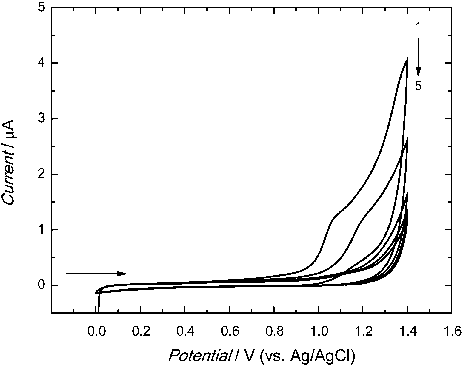 | ||
| Fig. 1 Potentiodynamic curves of 0.1 mM 1, 0.3 mM 2, 0.1 mM 3 in 0.1 M (TBA)ClO4 in acetonitrile–water solution (9:1, v:v) recorded on a 1 mm diameter Pt disk electrode for 5 potential cycles at the potential scan rate of 50 mV s−1. | ||
Moreover, the above electropolymerization procedure was used for deposition of the MIP-carnosine film on the Au-QCRs for PM measurements (Fig. 2). In the first potential cycle, the anodic peak appeared at ∼1.20 V (Fig. 2a). This sharp peak converted into a broad peak with a hump at ∼1.0 in the second cycle. Importantly, in subsequent cycles these two peaks merged to form one broad peak at more positive potentials.67 Moreover, the anodic current decreased with each cycle. A cathodic peak was present at ∼0.60 V. It increased in the first three cycles, and then decreased. Deposition of the MIP-carnosine film on the Au-QCR was accompanied by a decrease of the resonance frequency (Fig. 2b) indicating the increase of the Au-QCR mass. This frequency decrease was lower in each consecutive cycle. Moreover, the film deposition caused only a minor dynamic resistance decrease (Fig. 2c) indicating only negligible changes in the film viscosity and density.
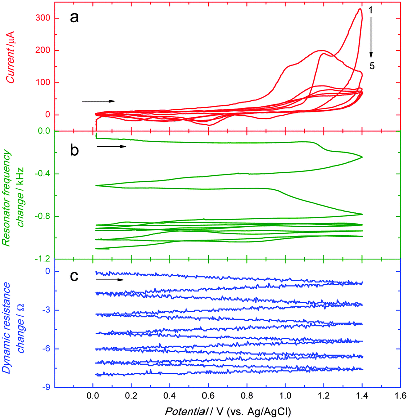 | ||
| Fig. 2 Simultaneously recorded curves of the potential dependence of (a) current as well as the change in (b) resonant frequency and (c) dynamic resistance for deposition of an MIP-carnosine film by potentiodynamic electropolymerization at 10 MHz Au-QCR. The solution composition was the same as that used for recording curves shown in Fig. 1. | ||
Extraction of the carnosine template from the MIP-carnosine film
A strongly basic solution, used for extraction of the carnosine template, caused deprotonation of carnosine (pKa1 = 2.76 of –COOH, pKa2 = 6.72 of N–H in the imidazole ring, and pKa3 = 9.32 of –NH2 of the β-alanine residue68). This deprotonation resulted in decomposition of the supramolecular complex of the crown ether moiety of 3 with the –NH2 group of 1. Moreover, it led to rupture of all hydrogen bonds because of formation of carboxylates and imidazolate, and hence electrostatic repulsion of the carboxylate recognition sites of 2′ and 2′′ by the carboxylate binding sites of carnosine.To confirm the completion of the extraction, the DPV experiments exploiting the “gating effect” were performed (Fig. 3). In these experiments, K4[Fe(CN)6] was used as the redox probe. The bare electrode was freely accessible for the Fe(CN)64−/Fe(CN)63− electrode reaction (curve 1 in Fig. 3). However, this probe could not approach the electrode surface coated by the MIP-carnosine film, as manifested by no current flow (curve 2 in Fig. 3). The carnosine template extraction from the film emptied molecular cavities, and hence facilitated the diffusion of the probe to the electrode surface through the MIP film (curves 3–5 in Fig. 3). After 20 min, the DPV current peak increase for the redox probe slowed down. We extracted the MIP film for additional 10 min for complete template removal. The completion of extraction was confirmed by XPS measurements (Fig. S2, ESI†).
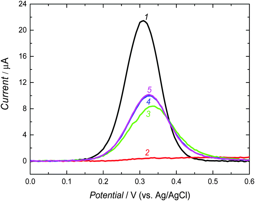 | ||
| Fig. 3 The DPV curves of 0.1 M K4[Fe(CN)6] in 0.1 M KNO3 on (1) the bare Pt disk electrode as well as for the Pt disk electrode coated with the MIP-carnosine film (2) before and after extraction of the carnosine template with 0.1 M NaOH for (3) 10 min, (4) 20 min, and (5) 30 min. | ||
In the N 1s XPS spectra, the N 1s electron binding energy was chosen as a marker for confirming the presence, and then the absence of the carnosine template in the MIP film before and after extraction, respectively, (Fig. S2a and b, ESI†). The composed band at ∼400 eV corresponds to the electrons of nitrogen atoms at different positions in the carnosine template imprinted in the polymer. The deconvoluted spectrum shows two peaks, i.e., one at 399.12 eV and the other at 401.42 eV. These peaks can be assigned to electrons of the nitrogen atom of the histidine residue or the nitrogen atom of the peptide bond, and primary aliphatic amine, –NH3+,69 respectively. It is difficult to distinguish bands of the nitrogen atoms of the imidazole ring and those of the peptide bond because of peak overlapping. Nevertheless, the presence of the N 1s peaks (Fig. S2a, ESI†) confirms template imprinting in the MIP. Then, the absence of these peaks after carnosine template extraction (Fig. S2b, ESI†) proves completion of this extraction.
The Raman spectra of the carnosine powder as well as of MIP films before and after template extraction were recorded (Fig. S3, ESI†). In Fig. S3a (ESI†), there are peaks characteristic of carnosine. At 1407 and 630 cm−1, there are peaks corresponding to in-plane deformation vibrations and a strong peak responsible for stretching vibration of the COO− moiety, respectively. Peaks at 1433, 1469, 1498, 1572, and 1666 cm−1 can be assigned to vibrations of the imidazole ring.70 A peak corresponding to the C–H in-plane deformation vibration in the imidazole ring is seen at 990 cm−1.70 Fig. S3b (ESI†) presents the Raman spectrum of the MIP film before removal of the carnosine template. This spectrum shows peaks ascribed to vibrations related to thiophenes and carnosine.66 That is, the peak at 1441 cm−1 corresponds to stretching vibrations of the imidazole ring. After extraction of the carnosine template (Fig. S3c, ESI†) intensity of this peak decreased, thus confirming removal of this template.
The Raman spectra of the MIP film are dominated by peaks originating from the C–C stretching vibrations. Fig. S4 (ESI†) shows peaks corresponding to vibrations of the N–H⋯O bonds formed between 1 and 3. A weak peak at 1686 cm−1 observed before template extraction (Fig. S4a, ESI†) disappeared after the extraction (Fig. S4b, ESI†). Blue vertical lines represent theoretically calculated normal modes. They can be assigned to vibrations of the NH3+ group of carnosine interacting with oxygen atoms of the crown ether moiety of 3. In the red frame (Fig. S4a, ESI†), the scaled peak at 1645 cm−1 (experimental 1710 cm−1) contains 50% of the H–N–H bending vibration. Formation of hydrogen bonds of the guest–host complex resulted in pushing this peak toward a higher scaled Raman shift of 1660 cm−1 (experimental 1742 cm−1). The difference between these peaks for the experimental data is 40–41 cm−1 while our calculations predicted the shift of 32 cm−1 in view of the 29 cm−1 calculated shift from the literature.71
Surface morphology of the MIP-carnosine film
The AFM imaging of the MIP-carnosine film before (Fig. 4a) and after (Fig. 4b) carnosine template extraction revealed that the film was homogenous and composed of small grains of ∼10 nm in diameter. These grains provided a large surface area (Fig. 4a and b), thus maximizing interactions of the MIP with the analyte molecules. Before template extraction, thickness of 240(±24) nm and roughness of 1.5(±0.1) nm of the MIP-carnosine film were determined. Interestingly, this thickness was practically the same after carnosine template removal, then being 229(±24) nm. Therefore, the possible polymer swelling and contribution of this swelling to the measured capacity is excluded that way.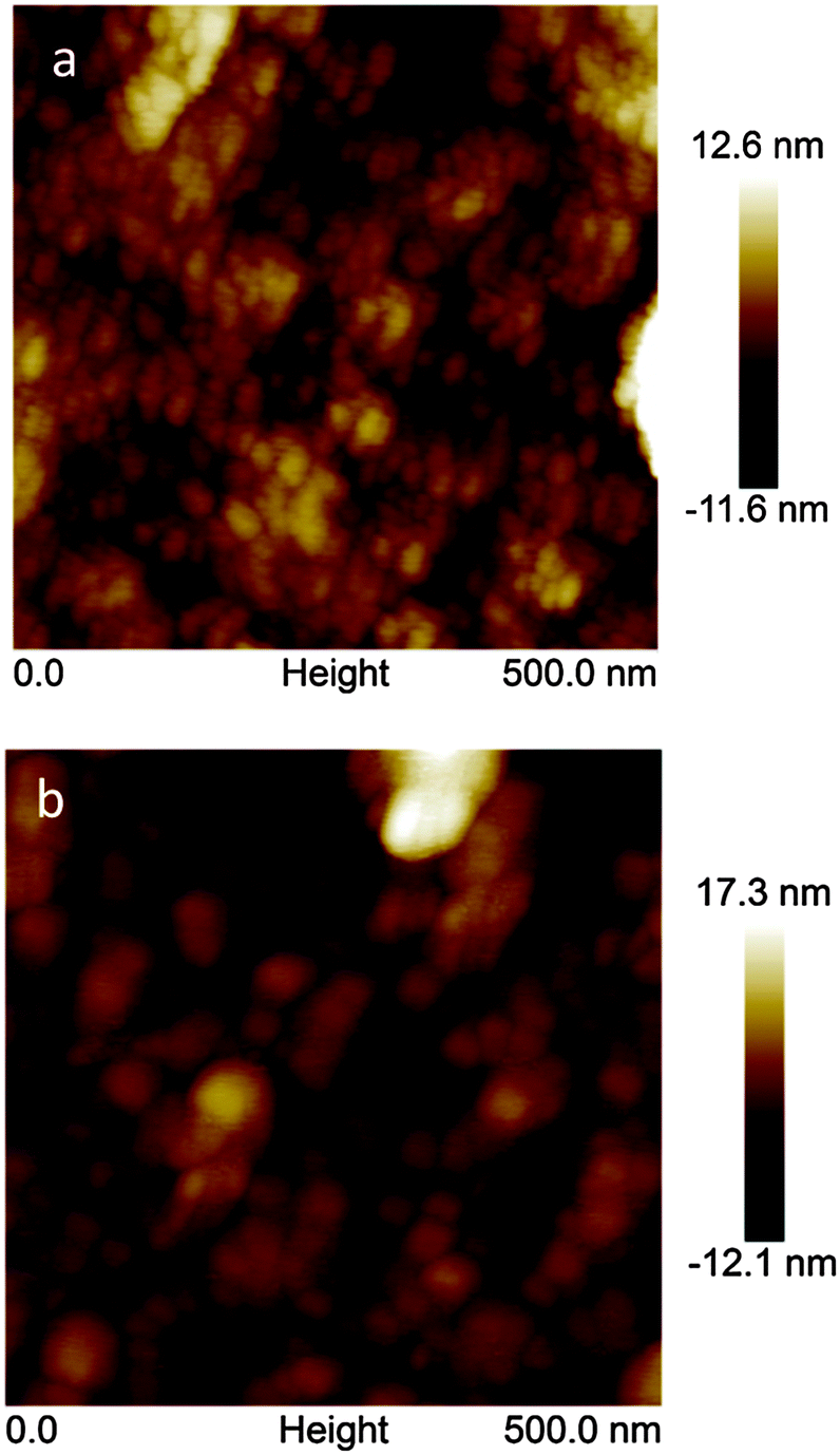 | ||
| Fig. 4 The atomic force microscopy (AFM) images of the MIP-carnosine film deposited over Au film-coated glass slides of the surface area of (0.5 × 0.5) μm2 (a) before and (b) after extraction of the carnosine template. | ||
Determination of carnosine using capacity measured by impedimetry under FIA conditions
A Pt disk electrode coated with the carnosine-extracted MIP-carnosine film was used for IC measurements of carnosine determination under FIA conditions. The impedance measurements were performed at the direct current potential offset of 0.50 V and the alternating current potential amplitude of 10 mV. During measurements, the frequency was kept constant, f = 20 Hz. At this low frequency, the MIP film coated electrode mainly reveals capacitive properties. This capacity was low at low potential and it rapidly increased with the potential increase. However, the capacity was low again when the polymer was completely oxidized. Therefore, the potential of 0.50 V was selected as an optimized potential in these measurements.72 Importantly, this potential was much lower than that of oxidation of the thiophene polymer. The double-layer capacity was calculated from the equation | (1) |
 | (2) |
The capacity increased after injection of the carnosine analyte solutions, and then decreased to form peaks (Fig. 5). The concentration of the carrier electrolyte solution was kept high (0.1 M LiNO3) to minimize the contribution of the diffuse-layer capacity to the total capacity measured. Therefore, this capacity increase was related to the capacity increase of the compact part of the double layer. Hence, the Helmholtz model of the double layer could be adopted. In this model, capacity solely depends upon the electric permittivity, ε, (ε0 being electric permittivity of free space) and the thickness of the compact part of the double layer, d, as eqn (3) describes73
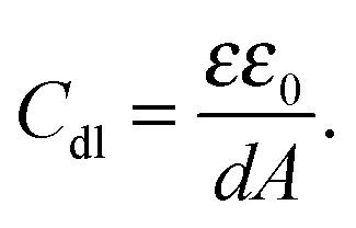 | (3) |
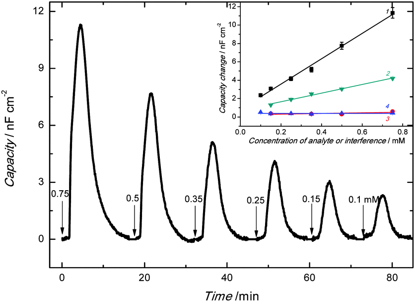 | ||
| Fig. 5 The capacity change with time under FIA conditions for the 100 μL injections of carnosine in 0.1 M LiNO3 at the applied potential of 0.5 V vs. Ag/AgCl and the frequency of 20 Hz for the 1 mm diameter Pt disk electrode coated with the carnosine template extracted MIP-carnosine film. The carnosine concentration is indicated at each peak. The inset shows calibration plots on the Pt disk electrode coated with the carnosine template extracted MIP-carnosine film for (1) carnosine and its structural analogues (2) L-histidine, (3) L-anserine and (4) carcinine. The flow rate of 0.1 M LiNO3, used as the carrier solution, was 35 μL min−1. | ||
The decrease of thickness of the compact part of the double layer and/or the increase of relative permittivity caused by the appearance of the carnosine ions in the MIP may result in the Cdl increase. As expected, capacity of the imprinted polymer film increased with the increase of the concentration of the injected carnosine analyte sample solution (Fig. 5).
The linear dynamic concentration range of at least 0.1 to 0.75 mM determined (inset in Fig. 5) was characterized by the linear regression equation of the calibration plot of Cdl (μF cm−2) = 0.014(±5.6 × 10⁻⁴) (μF cm−2 mM−1) ccarnosine (mM) + 8.0 × 10⁻⁴(±2.3 × 10⁻⁴) (μF cm−2) with the correlation coefficient of 0.992 and sensitivity of 0.014(±5.6 × 10⁻⁴) μF cm−2 mM−1. At S/N = 3, the limit of detection reached 20 μM carnosine.
For selectivity studies, structural analogues of carnosine, including anserine, carcinine, and histidine, were chosen. Our chemosensor appeared appreciably selective toward these analogues (inset to Fig. 5). That is, sensitivity to carnosine was ∼38 times that to anserine being 3.6 × 10⁻⁴(±2.8 × 10⁻⁴) μF cm−2 mM−1 and over 100 times that to carcinine, which was 4.2 × 10⁻⁸(±1.3 × 10⁻⁴) μF cm−2 mM−1. However, selectivity to histidine, which is a part of the carnosine dipeptide analyte, was ∼3 times lower than that to carnosine equaling 0.0047(±2.4 × 10⁻⁴) μF cm−2 mM−1. Not surprisingly, molecular cavities created for carnosine were sufficiently big to accommodate small histidine molecules. Moreover, our quantum chemical calculations confirmed this result. That is, the strength of histidine binding by the molecular cavity imprinted with carnosine was half of that of carnosine binding.
Determination of the imprinting factor using piezoelectric microgravimetry under FIA conditions
The PM technique was used to determine the imprinting factor of the MIP film. For that purpose, the Au-QCR coated with the MIP-carnosine film was mounted on the EQCM 5610 holder, and then carnosine was determined under FIA conditions. The change in the resonant frequency, Δf, is related to the change in mass, Δm, of a rigid film deposited on the Au-QCR surface, as described by the Sauerbrey relation, (eqn (4)) | (4) |
The frequency decreased, and then increased to its baseline after each consecutive injection of the carnosine sample solutions of different concentrations (Fig. 6). This frequency behavior indicated the binding of the carnosine molecules by the empty cavities of the film, and then releasing these molecules with excess of the carrier solution. Apparently, the higher the absolute change in the resonant frequency, the higher was the carnosine concentration.
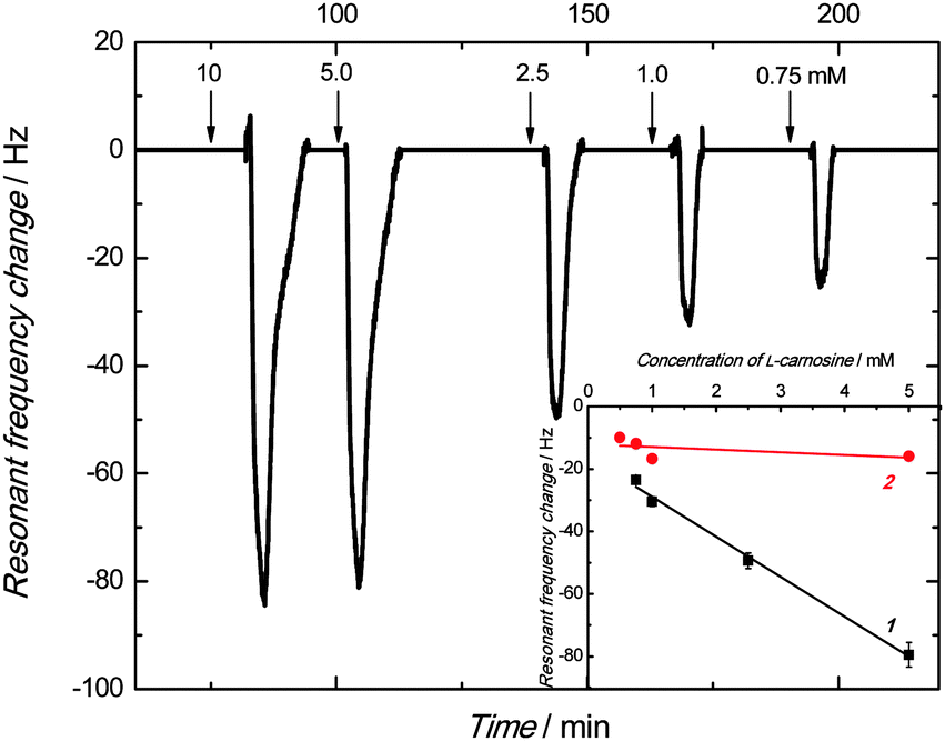 | ||
| Fig. 6 The resonant frequency change with time under FIA conditions for 100 μL injections of carnosine in 0.1 M LiNO3 on the Au-QCR coated with the carnosine template extracted MIP-carnosine film. The flow rate of 0.1 M LiNO3, used as the carrier solution, was 35 μL min−1. The carnosine concentration is indicated at each peak. The inset represents the PM calibration curves for carnosine on the Au-QCR coated with the films of (1) MIP and (2) NIP. | ||
The linear dynamic concentration range of 0.75 to 5 mM obtained was characterized by the linear regression equation of Δf (Hz) = −12.8(±0.6) (Hz mM−1) ccarnosine (mM) – 16.1(±1.8) (Hz) with the correlation coefficient and sensitivity of 0.993 and −12.8(±0.6) Hz mM−1, respectively.
A similar measurement was performed for the NIP film coated Au-QCR. The sensitivity of this control chemosensor toward carnosine within the linear concentration range of 0.5 to 5 mM was low. The obtained calibration curve obeyed the linear regression equation of Δf (Hz) = −0.86(±0.8) (Hz mM−1) ccarnosine (mM) – 12.1(±2.3) (Hz). The imprinting factor, determined as the ratio of sensitivity to carnosine of the MIP film to that of the NIP film, was as high as 14.9.
Conclusions
The carnosine template was successfully imprinted in a conducting polymer matrix. Computational modeling appeared to be a powerful tool in predicting the formation of a stable pre-polymerization complex of the carnosine template with suitably selected bis(2,2′-bithien-5-yl)methane derived functional monomers. Electropolymerization under potentiodynamic conditions enabled depositing MIP films on different electrodes including the Pt disk electrode and the Au-QCR. Moreover, it allowed controlling the film thickness and its morphology. The MIP-carnosine film, applied as a recognition unit of the IC chemosensor, proved to be a sensitive tool for fast and selective determination of carnosine with an appreciable detectability of 20 μM. Owing to the presence of multiple modes of binding of the analyte with the MIP recognition sites, the fabricated chemosensor manifested high selectivity to structural carnosine analogues including anserine and carcinine as well as histidine, the latter being a part of the carnosine molecule. With its high (14.9) imprinting factor, our chemosensor is suitable for clinical analysis directed toward early diagnosis of diseases associated with the abnormal concentration of carnosine in body fluids.Acknowledgements
The present research was financially supported by the Polish National Centre of Science through the Grants numbers NCN 2011/03/D/ST4/02596 to P.S.S. and NCN 2014/15/B/NZ7/01011 to W.K. as well as by US National Science Foundation grant number 1401188 to F.D.Notes and references
- F. Bellia, G. Vecchio and E. Rizzarelli, Molecules, 2014, 19, 2299–2329 CrossRef PubMed.
- K. Bauer, Neurochem. Res., 2005, 30, 1339–1345 CrossRef CAS PubMed.
- A. R. Hipkiss, J. E. Preston, D. T. M. Himsworth, V. C. Worthington, M. Keown, J. Michaelis, J. Lawrence, A. Mateen, L. Allende, P. A. M. Eagles and N. J. Abbott, Ann. N. Y. Acad. Sci., 1998, 854, 37–53 CrossRef CAS PubMed.
- C. A. Hill, R. C. Harris, H. J. Kim, B. D. Harris, C. Sale, L. H. Boobies, C. K. Kim and J. A. Wise, Amino Acids, 2007, 32, 225–233 CrossRef CAS PubMed.
- G. Begum, A. Cunliffe and M. Leveritt, Int. J. Sport Nutr. Exercise Metab., 2005, 5, 493–514 Search PubMed.
- R. C. Harris, J. A. Wise, K. A. Price, H. J. Kim, C. K. Kim and C. Sale, Amino Acids, 2012, 43, 5–12 CrossRef CAS PubMed.
- A. Neidle and J. Kandera, Brain Res., 1974, 80, 359–364 CrossRef CAS PubMed.
- L. Bonfantia, P. Peretto, S. D. Marchisc and A. Fasoloc, Prog. Neurobiol., 1999, 59, 333–353 CrossRef.
- F. L. Margolis, Science, 1974, 184, 909–911 CAS.
- E. J. Baran, Biochemistry, 2000, 65, 789–797 CAS.
- P. Q. Trombley, M. S. Horning and L. J. Blakemore, Biochemistry, 2000, 65, 807–816 CAS.
- D. Mizuno and M. Kawahara, J. Vasc. Med. Surg., 2014, 2, 146 Search PubMed.
- H. Abe, Biochemistry, 2000, 65, 757–765 CAS.
- R. Kohen, Y. Yamamoto, K. C. Cundy and B. N. Ames, PNAS, 1988, 85, 3175–3179 CrossRef CAS.
- E. A. Decker and H. Faraji, J. Am. Oil Chem. Soc., 1990, 67, 650–652 CrossRef CAS.
- S. Zhou and E. A. Decker, J. Agric. Food Chem., 1999, 47, 51–55 CrossRef CAS PubMed.
- M. A. Babizhayev, M. C. Seguin, J. Gueyne, R. P. Evstigneeva, E. A. Ageyeva and G. A. Zheltukhina, Biochem. J., 1994, 304, 509–516 CrossRef CAS PubMed.
- H. Yan and J. J. Harding, Biochim. Biophys. Acta, 2005, 1741, 120–126 CrossRef CAS PubMed.
- N. W. Seidler, G. S. Yeargans and T. G. Morgan, Arch. Biochem. Biophys., 2004, 427, 110–115 CrossRef CAS PubMed.
- V. P. Reddy, M. R. Garrett, G. Perry and M. A. Smith, Sci. Aging Knowledge Environ., 2005, 2005, 12 Search PubMed.
- M. Tamba and A. Torreggiani, Int. J. Radiat. Biol., 1999, 75, 1177–1188 CrossRef CAS PubMed.
- K. Nagai, A. Niijima, T. Yamano, H. Otani, N. Okumra, N. Tsuruoka, M. Nakai and Y. Kiso, Exp. Biol. Med., 2003, 228, 1138–1145 CAS.
- A. R. Hipkiss, J. Alzheimer's Dis., 2007, 11, 229–240 CAS.
- A. Boldyrev, T. Fedorova, M. Stepanova, I. Dobrotvorskaya, E. Kozlova, N. Boldanova, G. Bagyeva, I. Ivanova-Smolenskaya and S. Illarioshkin, Rejuvenation Res., 2008, 11, 821–827 CrossRef CAS PubMed.
- F. Attanasio, S. Cataldo, S. Fisichella, S. Nicoletti, V. G. Nicoletti, B. Pignataro, A. Savarino and E. Rizzarelli, Biochemistry, 2009, 48, 6522–6531 CrossRef CAS PubMed.
- F. Pfister, E. Riedl, Q. Wang, F. v. Hagen, M. Deinzer, M. C. Harmsen, G. Molema, B. Yard, Y. Feng and H.-P. Hammes, Cell. Physiol. Biochem., 2011, 28, 125–136 CrossRef CAS PubMed.
- Y. Tsuruta, K. Maruyama, H. Inoue, K. Kosha, Y. Date, N. Okamura, S. Eto and E. Kojima, J. Chromatogr. B: Anal. Technol. Biomed. Life Sci., 2010, 878, 327–332 CrossRef CAS PubMed.
- M. C. Jackson and J. F. Lenney, Inflammation Res., 1996, 45, 132–135 CrossRef CAS PubMed.
- T. L. Perry, S. Hansen, B. Tischler, R. Bunting and K. Berry, N. Engl. J. Med., 1967, 277, 1219–1227 CrossRef CAS PubMed.
- I. Everaert, Y. Taes, E. D. Heer, H. Baelde, A. Zutinic, B. Yard, S. Sauerhöfer, L. Vanhee, J. Delanghe, G. Aldini and W. Derave, Am. J. Physiol.: Renal, Fluid Electrolyte Physiol., 2012, 302, F1537–F1544 CrossRef CAS PubMed.
- P. L. Hartlage, R. A. Roesel, A. G. Eller and F. A. Hommes, J. Inherited Metab. Dis., 1982, 5, 13–14 CrossRef.
- S. M. Willi, in NORD guide to rare disorders, ed. N. O. f. R. Disorders, Lippincott Williams & Wilkins, USA, 1st edn, 2003, p. 435 Search PubMed.
- J. J. O'Dowd, D. J. Robins and D. J. Miller, Biochim. Biophys. Acta, 1988, 967, 241–249 CrossRef.
- Y. J. Park, S. L. Volpe and E. A. Decker, J. Agric. Food Chem., 2005, 53, 4736–4739 CrossRef CAS PubMed.
- L. Mora, M. A. Sentandreu and F. Toldrá, J. Agric. Food Chem., 2007, 55, 4664–4669 CrossRef CAS PubMed.
- Y. Huang, J. Duan, H. Chen, M. Chen and G. Chen, Electrophoresis, 2005, 26, 593–599 CrossRef PubMed.
- S. Zhao, Y. Huang, M. Shi, J. Huang and Y.-M. Liu, Anal. Biochem., 2009, 393, 105–110 CrossRef CAS PubMed.
- M. Jozanović, M. Medvidović-Kosanović and M. Sak-Bosnar, Int. J. Electrochem. Sci., 2015, 10, 6548–6557 Search PubMed.
- S. Rochat, J. Gao, X. Qian, F. Zaubitzer and K. Severin, Chem. – Eur. J., 2010, 16, 104–113 CrossRef CAS PubMed.
- C. Alexander, H. S. Andersson, L. I. Andersson, R. J. Ansell, N. Kirsch, I. A. Nicholls, J. O'Mahony and M. J. Whitcombe, J. Mol. Recognit., 2006, 19, 106–180 CrossRef CAS PubMed.
- T.-P. Huynh, A. Wojnarowicz, M. Sosnowska, S. Srebnik, T. Benincori, F. Sannicolò, F. D'Souza and W. Kutner, Biosens. Bioelectron., 2015, 70, 153–160 CrossRef CAS PubMed.
- P. S. Sharma, M. Dabrowski, K. Noworyta, T.-P. Huynh, C. B. KC, J. W. Sobczak, P. Pieta, F. D'Souza and W. Kutner, Anal. Chim. Acta, 2014, 844, 61–69 CrossRef CAS PubMed.
- K. Haupt and K. Mosbach, Chem. Rev., 2000, 100, 2495–2504 CrossRef CAS PubMed.
- P. S. Sharma, F. D'Souza and W. Kutner, TrAC, Trends Anal. Chem., 2012, 34, 59–77 CrossRef CAS.
- B. Okutucu and F. Zihnioglu, Mater. Sci. Eng., C, 2012, 32, 1174–1178 CrossRef CAS.
- T.-P. Huynh, P. S. Sharma, M. Sosnowska, F. D'Souza and W. Kutner, Prog. Polym. Sci., 2015, 47, 1–25 CrossRef CAS.
- P. S. Sharma, A. Pietrzyk-Le, F. D'Souza and W. Kutner, Anal. Bioanal. Chem., 2012, 402, 3177–3204 CrossRef CAS PubMed.
- A. Pietrzyk, W. Kutner, R. Chitta, M. E. Zandler, F. D'Souza, F. Sannicolò and P. R. Mussini, Anal. Chem., 2009, 81, 10061–10070 CrossRef CAS PubMed.
- A. Pietrzyk, S. Suriyanarayanan, W. Kutner, R. Chitta and F. D'Souza, Anal. Chem., 2009, 81, 2633–2643 CrossRef CAS PubMed.
- A. Pietrzyk, S. Suriyanarayanan, W. Kutner, R. Chitta, M. E. Zandler and F. D'Souza, Biosens. Bioelectron., 2010, 25, 2522–2529 CrossRef CAS PubMed.
- T.-P. Huynh, C. B. KC, W. Lisowski, F. D'Souza and W. Kutner, Bioelectrochemistry, 2013, 93, 37–45 CrossRef CAS PubMed.
- M. J. Frisch, G. W. Trucks, H. B. Schlegel, G. E. Scuseria, M. A. Robb, J. R. Cheeseman, G. Scalmani, V. Barone, B. Mennucci, G. A. Petersson, H. Nakatsuji, M. Caricato, X. Li, H. P. Hratchian, A. F. Izmaylov, J. Bloino, G. Zheng, J. L. Sonnenberg, M. Hada, M. Ehara, K. Toyota, R. Fukuda, J. Hasegawa, M. Ishida, T. Nakajima, Y. Honda, O. Kitao, H. Nakai, T. Vreven, J. A. Montgomery Jr., J. E. Peralta, F. Ogliaro, M. Bearpark, J. J. Heyd, E. Brothers, K. N. Kudin, V. N. Staroverov, R. Kobayashi, J. Normand, K. Raghavachari, A. Rendell, J. C. Burant, S. S. Iyengar, J. Tomasi, M. Cossi, N. Rega, J. M. Millam, M. Klene, J. E. Knox, J. B. Cross, V. Bakken, C. Adamo, J. Jaramillo, R. Gomperts, R. E. Stratmann, O. Yazyev, A. J. Austin, R. Cammi, C. Pomelli, J. W. Ochterski, R. L. Martin, K. Morokuma, V. G. Zakrzewski, G. A. Voth, P. Salvador, J. J. Dannenberg, S. Dapprich, A. D. Daniels, Ö. Farkas, J. B. Foresman, J. V. Ortiz, J. Cioslowski and D. J. Fox, Gaussian 09, Gaussian, Inc., Wallington CT, 2009 Search PubMed.
- M. H. Jamróz, Vibrational energy distribution analysis, Spectroscopy and molecular modeling group, Institute of nuclear chemistry and technology, Warsaw, Poland, 2004–2010.
- M. H. Jamróz, Spectrochim. Acta, Part A, 2013, 114, 220–230 CrossRef PubMed.
- M. Wojdyr, J. Appl. Crystallogr., 2010, 43, 1126–1128 CrossRef CAS.
- M. H. Jamróz, SPESCA, Spectroscopy and molecular modeling group, Institute of nuclear chemistry and technology, Warsaw, Poland, 2014.
- A. Kochman, A. Krupka, J. Grissbach, W. Kutner, B. Gniewinska and L. Nafalski, Electroanalysis, 2006, 18, 2168–2173 CrossRef CAS.
- W. Koh, W. Kutner, M. T. Jones and K. M. Kadish, Electroanalysis, 1993, 5, 209–214 CrossRef CAS.
- B. Soucaze-Guillous and W. Kutner, Electroanalysis, 1997, 9, 32–39 CrossRef CAS.
- A. Pietrzyk, S. Suriyanarayanan, W. Kutner, E. Maligaspe, M. E. Zandler and F. D'Souza, Bioelectrochemistry, 2010, 80, 62–72 CrossRef CAS PubMed.
- M. Hiraoka, Crown ethers and analogue compounds, Elsevier, 1992 Search PubMed.
- T. Koide and K. Ueno, J. Chromatogr. A, 2001, 909, 305–315 CrossRef CAS PubMed.
- R. Kuhn, Electrophoresis, 1999, 20, 2605–2613 CrossRef CAS PubMed.
- M. Schafer, Angew. Chem., Int. Ed., 2003, 42, 1896–1899 CrossRef CAS PubMed.
- J. W. Steed and J. L. Atwood, Supramolecular Chemistry, Wiley and Sons, Ltd., United Kingdom, 2nd edn, 2009 Search PubMed.
- G. Socrates, Infrared and Raman charasteristic group frequecies, Wiley, New York, 2001 Search PubMed.
- D. C. Apodaca, R. B. Pernites, R. R. Ponnapati, F. R. D. Mundo and R. C. Advincula, ACS Appl. Mater. Interfaces, 2011, 3, 191–203 CAS.
- A. A. Boldyrev, G. Aldini and W. Derave, Physiol. Rev., 2013, 93, 1803–1845 CrossRef CAS PubMed.
- T. Matsukura, T. Takahashi, Y. Nishimura, T. Ohtani, M. Sawada and K. Shibata, Chem. Pharm. Bull., 1990, 38, 3140–3146 CrossRef CAS PubMed.
- A. Torreggiani, M. Tamba and G. Fini, Biopolymers, 2000, 57, 149 CrossRef PubMed.
- N. S. Myshakina, Z. Ahmed and S. A. Asher, J. Phys. Chem. B, 2008, 112, 11873–11877 CrossRef PubMed.
- N. Mermilliod and J. Tanguy, J. Electrochem. Soc., 1986, 133, 1073–1079 CrossRef CAS.
- A. J. Bard and L. R. Faulkner, Electrochemical methods funadamentals and application, Wiley India, 2nd edn, 2010 Search PubMed.
Footnote |
| † Electronic supplementary information (ESI) available: XPS and Raman spectra of MIP-carnosine before and after carnosine extraction, and theoretical and experimental Raman spectra of the MIP film. See DOI: 10.1039/c5tb02260f |
| This journal is © The Royal Society of Chemistry 2016 |