 Open Access Article
Creative Commons Attribution 3.0 Unported Licence
Mixed co-solvent engineering of PEDOT:PSS to enhance its conductivity and hybrid solar cell properties†
Joseph Palathinkal
Thomas
and
Kam Tong
Leung
*
WATLab and Department of Chemistry, University of Waterloo, Waterloo, Ontario N2L 3G1, Canada. E-mail: tong@uwaterloo.ca
First published on 12th October 2016
Abstract
Conducting polymers, such as poly(3,4-ethylenedioxy thiophene):poly(styrenesulfonate) (PEDOT:PSS), have gained significant interest for their use in organic and organic–inorganic electronic device applications. Further enhancement in the conductivity of this polymer could accelerate its widespread use in electronic device applications. In addition, hybrid solar cells made of this p-type conducting polymer on Si have attracted a lot of attention in the fabrication of low-cost high-efficiency devices. Here, we demonstrate the effect of adding a mixed co-solvent of ethylene glycol and methanol in PEDOT:PSS to improve its conductivity and hence to enhance the performance of a hybrid planar Si solar cell. Based on our results, we establish a morphological model to explain the microstructure modification of PEDOT and PSS that contributes to the enhanced properties. We are able to engineer a thinnest PSS layer around individual PEDOT grains by adding a mixed co-solvent in PEDOT:PSS and achieve a highly conducting PEDOT:PSS film and a PEDOT:PSS/planar-Si cell with the highest photoconversion efficiency of 14.6% reported to date. Our present approach to generate highly conductive PEDOT:PSS by mixed co-solvent addition can also be used to improve the performance of other organic electronic devices based on PEDOT:PSS.
Introduction
Conducting polymers have recently gained significant interest for their wide range of applications in organic and organic–inorganic electronic devices.1–3 Among the many different types of technologically relevant conducting polymers, poly(3,4-ethylenedioxy thiophene):poly(styrenesulfonate) (PEDOT:PSS) is an especially important one, mainly because of its high conductivity and optical transparency as well as its aqueous formulation, making it easy to use in simple and low-cost device fabrication processes.1–5 There have been many efforts to enhance the conductivity of PEDOT:PSS by adding co-solvents in its solution form6–8 and by post-treatments on its thin film form.4,9–11 Among the diverse choice of co-solvents, two different co-solvents, ethylene glycol (EG) and dimethyl sulfoxide (DMSO), have been found to be especially efficient in enhancing the conductivity of PEDOT:PSS. Recently, we reported that 7 wt% EG addition is most effective in increasing the conductivity of the highly conducting version of PEDOT:PSS (Clevios, PH1000) in comparison with the other commonly used co-solvent DMSO.7On the other hand, there have been other efforts to enhance the conductivity of PEDOT:PSS films by using post-treatments.4,9–11 This approach is effective in reducing the surface resistivity, but is limited in changing the bulk properties. Furthermore, in order to perform this process, deposition of the PEDOT:PSS film must ideally be carried out as the first step in the device fabrication process. Otherwise, post-treatments such as acid treatment4,10 may damage other device components unless they are well isolated or protected. This makes the device fabrication process more complex. Furthermore, acid-based treatments also require the usual precaution associated with acid chemistry. Because of the widespread use of this polymer in diverse electronic device applications, improving the conductivity of this polymer by a safer and more facile approach remains an active area of research. Understanding the relationship between its structural modification and conductivity enhancement is therefore extremely important to further advance the performance of PEDOT:PSS-based electronic devices such as hybrid solar cells.
Hybrid solar cells comprising PEDOT:PSS and n-type Si have been extensively studied as potential low-cost high-efficiency devices.2,9,12–14 The simple device fabrication process based primarily on spin-coating PEDOT:PSS on n-type Si is particularly attractive for low-cost manufacturing of solar cells. However, most of the solar cells with high photoconversion efficiency (PCE) performance have thus far been fabricated on surface-structured Si substrates,9,12,15 with post-treatment of PEDOT:PSS films,13 or with the use of different interlayer materials2,16 between the top or bottom electrodes. While these methods have been reported to be effective in creating high-efficiency solar cells, they also increase the complexity (and cost) of the device fabrication processes. High-performance planar single-junction solar cells have considerable advantages in terms of processing and cost, because they do not require complex device fabrication processes. A planar single-junction hybrid solar cell with very high efficiency therefore offers great potential for production-ready, low-cost device applications.
Here, we report that a mixed co-solvent of EG and methanol (MeOH) can be used to engineer the PEDOT:PSS grains to dramatically enhance their conductivity. Indeed, this simple solution-based film fabrication process could convert the PEDOT:PSS film into its highest conducting form, in comparison with all other earlier reports to date. A morphological model is drawn based on transmission electron microscopy, atomic force microscopy, X-ray photoelectron spectroscopy, and Raman spectroscopy studies, which are used to characterize the microstructure modifications and the enhanced conductivity. A hybrid solar cell made on a planar Si substrate using the mixed co-solvent engineered PEDOT:PSS film shows a very high efficiency exceeding 14.6%, which represents the highest PCE reported to date for this type of planar single-junction hybrid solar cell.
Experimental
Co-solvent modification of PEDOT:PSS
Highly conducting grade PEDOT:PSS (PH1000) from Clevios, and all other chemicals from Sigma-Aldrich were used as purchased. Two different co-solvents were used to mix with PEDOT:PSS to enhance its conductivity. Firstly, pure EG was used as the co-solvent in which the PEDOT:PSS was mixed with EG of an appropriately optimized amount of 7 wt%, which is designated here as E7. Secondly, a stock mixture of 50 wt% of EG and 50 wt% of MeOH was prepared and 12, 14, 16, and 18 wt% of the mixed co-solvents were then added to PEDOT:PSS, which are designated as EM12, EM14, EM16, and EM18, respectively. For comparison, 7 and 10 wt% of mixed co-solvent added PEDOT:PSS films (EM7 and EM10) were also prepared. Prior to spin coating, a 0.25 wt% fluorosurfactant (FS-300) was also introduced to the co-solvent and mixed co-solvent added PEDOT:PSS solutions to enhance their wettability on the substrates.Thin film and hybrid solar cell fabrication
All the spin-coating carried out in the present work was conducted at a spin rate of 6000 rpm for 1 min, and the samples were subsequently annealed at 109 ± 1 °C on a hot plate in air for 10 min. The hybrid solar cells were fabricated on phosphorus-doped, n-type Si(100) substrates (380 ± 25 μm thick, Virginia Semiconductor Inc.), with resistivity in the range of 0.08–0.10 ohm cm. The substrates were ultrasonically cleaned for 10 min consecutively in acetone, isopropyl alcohol, and Millipore water, and then dried under a nitrogen stream. The substrates were then immersed in 5% hydrofluoric acid (HF) for 2 min to remove the native oxide, followed by thorough rinsing in Millipore water. Al metal (200 nm thick) was deposited on the unpolished side of the Si substrate, to be used as the bottom electrode, in a dual-target magnetron sputtering system (EMS575X). After the Al deposition, the Si substrates were kept in ambient atmosphere to allow natural growth of a SiOx layer. The interface oxide layer thickness was appropriately optimized for the E7 and EM samples (Fig. S1 and S2, ESI†) prior to the PEDOT:PSS deposition on the Si substrate. A comb-type Ag metal grid electrode (50 nm thick), deposited through a shadow mask on the polymer layer by using magnetron sputtering, was used as the top electrode for the solar cell property measurement.Characterization
The sheet resistances were measured by using the four-point probe method (with a Signatone 4-point probing station and a Keithley 2400 source meter) or in a van der Pauw configuration (with an Ecopia HMS-5300 system). The reflectance spectra of the PEDOT:PSS films deposited on Si substrates without the Ag top electrodes, and the transmittance spectra of the PEDOT:PSS films deposited on glass substrates were obtained on a UV-Vis-NIR spectrophotometer (Perkin-Elmer Lambda 1050). Raman spectra were collected at room temperature with a laser wavelength of 785 nm and a laser power of 50 mW using a Bruker Senterra Raman confocal microscope. The integration time was 80 s and the resolution was 3–5 cm−1. X-ray photoelectron spectroscopy studies were carried out on a Thermo-VG Scientific ESCALab 250 microprobe equipped with a monochromatic Al Kα source (1486.6 eV). Peak fitting for the XPS spectra after correction with the Shirley background was performed by using the CasaXPS software. Time-of-flight secondary ion mass spectrometry (TOF-SIMS) measurement was conducted using an ION-TOF-5 system (IONTOF GmbH) equipped with a 2 m long reflectron time-of-flight analyzer operated in the negative polarity mode, and a Bi3+ (30 keV) analysis ion beam source and an Ar cluster ion (Ar1000+, 5 keV) sputtering source. Depth profiling was performed in the (non-interlaced) spectrometry mode with a cycle time of 200 μs and a sampling area of 150 × 150 μm2 and a sputtering area of 400 × 400 μm2. The TOF-SIMS spectra were mass-calibrated on Cx fragments prior to the depth profiling experiments. The depth profiles of PEDOT (C8H7SO3− ions), the fluorine (F− ions) from the surfactant, interface SiOx, and Si substrate components were analysed. The surface morphologies of the PEDOT:PSS films were examined by tapping-mode atomic force microscopy (AFM) on a Digital Instruments Dimension 3100 Nanoscope IV microscope. Transmission electron microscopy (TEM) measurements were carried out on a Zeiss Libra 200 MC microscope operated at 200 keV. Low-loss (or plasmon) energy-filtered TEM (EFTEM) images were acquired by using an exit slit with an appropriate slit width for the double-corrected omega energy filter.The solar cell properties were analysed by using a solar cell characterization system capable of both I–V and EQE measurements (PV Measurements IV5 and QEX10). The I–V measurements were performed under 100 mW cm−2 illumination using a class ABA solar simulator (with an AM 1.5G filter) in air. Prior to the I–V measurement, a Si reference cell (PVM782 with a BK7 window) was used to calibrate the light source intensity. An aluminium metal aperture mask was used to specify the area of the device (0.7 × 0.7 cm2) during the I–V measurement. The EQE measurements were carried out under monochromatic light (in between two fingers of the top comb electrode), as filtered by a dual-grating monochromator from a xenon arc lamp source, coupled with a germanium photodiode. For EQE measurements the approximate illumination area was 1 × 3.5 mm2.
Results and discussion
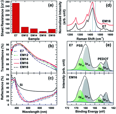
The sheet resistance, Rs, of mixed co-solvent added PEDOT:PSS films are compared in Fig. 1a. The tabulated conductivity values are shown in Table S1 (ESI†). A 7 wt% mixed co-solvent added PEDOT:PSS is found to have similar Rs as the E7 film (254 Ω □−1), while a 10 wt% mixed co-solvent added PEDOT:PSS shows ∼20% reduction in the Rs value to 199 Ω □−1 (Fig. S1, ESI†). The addition of 12 wt% of mixed co-solvent into PEDOT:PSS causes further significant reduction in Rs to 147 Ω □−1. Increase in the amount of mixed co-solvent in PEDOT:PSS to 14, 16, and 18 wt% results in only a further minor reduction of Rs to 140, 128, and 137 Ω □−1, respectively. The 16 wt% mixed co-solvent added PEDOT:PSS film represents the optimized film with the lowest reported Rs value among the as-prepared PEDOT:PSS films (without any post-treatment).7,11,17 Evidently, a minimum amount of 7–9 wt% EG, which is in effect present in the mixed co-solvent, is required to achieve the lowest sheet resistance.The transmittance spectra of all the PEDOT:PSS films on glass substrates in Fig. 1b show very high transmittance with the maximum above 95% at a wavelength of 435 nm. Overall, the highest transmittance in the entire wavelength region (300–1100 nm) is found for the EM16 sample, which supports its potential use in transparent conductive electronic applications. It is known that individual PEDOT:PSS films on Si substrates can act as an antireflection coating, which could be beneficial for photovoltaic applications. Fig. 1c compares the corresponding reflectance spectra of the E7 and EM12–EM18 films on Si substrates, along with that of a typical Si substrate. All the PEDOT:PSS films show highly antireflective properties with reflectance minima below 7.3%. The reflectance minima of mixed co-solvent added PEDOT:PSS films (EM12–EM16) at 586 nm evidently exhibit a blue shift of ∼50 nm in comparison with the E7 film. A further small blue shift of the reflectance minimum of ∼5 nm is observed for the EM18 film.
Raman spectroscopy has been used to examine the structure of PEDOT, with major Raman peaks for PEDOT observed between 1150 and 1610 cm−1.18–20Fig. 1d compares the Raman spectra of E7 and EM16 films. These spectra do not show any significant differences. The features marked by vertical lines at 1425 and 1453 cm−1 correspond to the symmetric stretching modes of quinoid Cα–Cβ and benzoid Cα![[double bond, length as m-dash]](https://www.rsc.org/images/entities/char_e001.gif) Cβ components, respectively. The peaks at 1530 and 1568 cm−1 are attributed to the asymmetric Cα–Cβ stretching modes. The peak at 1366 cm−1 can be assigned to Cβ
Cβ components, respectively. The peaks at 1530 and 1568 cm−1 are attributed to the asymmetric Cα–Cβ stretching modes. The peak at 1366 cm−1 can be assigned to Cβ![[double bond, length as m-dash]](https://www.rsc.org/images/entities/char_e001.gif) Cβ stretching vibrations while the features between 1200 and 1300 cm−1 correspond to Cα
Cβ stretching vibrations while the features between 1200 and 1300 cm−1 correspond to Cα![[double bond, length as m-dash]](https://www.rsc.org/images/entities/char_e001.gif) Cα′ stretching modes. The relative surface composition of PEDOT and PSS in the E7 and EM16 films could be estimated from XPS studies using the intensity ratios of their distinct S 2p peaks, shown in Fig. 1e.7,21 These spectra show two S 2p bands, each corresponding to a doublet of S 2p3/2 and S 2p1/2 components with a 1.2 eV spin–orbit splitting and a 2
Cα′ stretching modes. The relative surface composition of PEDOT and PSS in the E7 and EM16 films could be estimated from XPS studies using the intensity ratios of their distinct S 2p peaks, shown in Fig. 1e.7,21 These spectra show two S 2p bands, each corresponding to a doublet of S 2p3/2 and S 2p1/2 components with a 1.2 eV spin–orbit splitting and a 2![[thin space (1/6-em)]](https://www.rsc.org/images/entities/char_2009.gif) :
:![[thin space (1/6-em)]](https://www.rsc.org/images/entities/char_2009.gif) 1 intensity ratio. The weaker S 2p3/2 (2p1/2) peak at 163.7 (164.9) eV and the stronger S 2p3/2 (2p1/2) peak at 167.9 (169.0) eV correspond to the sulfur atoms of PEDOT and PSS, respectively. The more electronegative oxygen attachment in the sulfonate moiety could account for the higher S 2p binding energy of PSS. A discernible increase in the ratio of PEDOT to PSS with the addition of the mixed co-solvent in PEDOT:PSS is obtained (for the surface region).
1 intensity ratio. The weaker S 2p3/2 (2p1/2) peak at 163.7 (164.9) eV and the stronger S 2p3/2 (2p1/2) peak at 167.9 (169.0) eV correspond to the sulfur atoms of PEDOT and PSS, respectively. The more electronegative oxygen attachment in the sulfonate moiety could account for the higher S 2p binding energy of PSS. A discernible increase in the ratio of PEDOT to PSS with the addition of the mixed co-solvent in PEDOT:PSS is obtained (for the surface region).
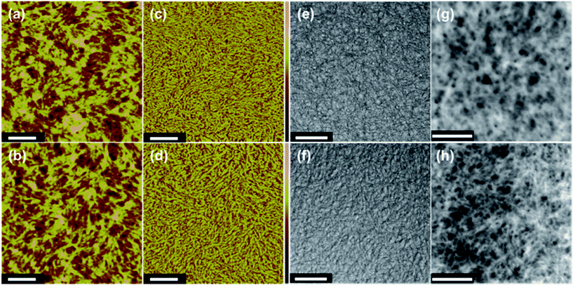
Atomic force microscopy (AFM) studies of the microstructure of the E7 film (Fig. 2a) indicate the presence of ellipsoidal grains, and closely packed and elongated interconnecting linkages among the grains in its corresponding phase image (Fig. 2c). The AFM image of the EM16 film (Fig. 2b) shows a similar morphology as that of the E7 film (Fig. 2a) but with slightly larger grain sizes, and longer and larger interconnecting linkages among grains in its phase image (Fig. 2d). The addition of a higher amount (18 wt%) of mixed co-solvent makes even larger interconnecting linkages in the film (Fig. S4, ESI†), which also affects its optical and electronic properties. The corresponding TEM images confirm similar grain sizes (Fig. 2e) as those observed in the AFM image of the E7 sample, but for the EM16 sample (Fig. 2f) well separated grains with dark coloured, thin filament-like grain boundaries are observed. The filament-like grain boundaries in EM16 suggest the aggregation of insulating and thicker PSS to the grain boundaries given an appropriate amount of mixed co-solvent in PEDOT:PSS. This is further supported by the corresponding low-loss (or plasmon) energy-filtered TEM (EFTEM) images shown in Fig. 2g and h. An appropriate exit slit width of a double-corrected omega filter was used to select an energy window of 10 to 40 eV from the EELS spectrum in order to form the images (see Fig. S5, ESI†). The low-loss EFTEM images show higher contrast for the electron density rich regions, which represent the signature of PSS in the grain boundaries of the PEDOT grains. In the E7 sample, these PSS features covering the PEDOT grains appear bright and thick (Fig. 2g). In contrast, considerably sharper and thinner (electron dense) boundary lines around dark regions are observed in the corresponding EM16 image (Fig. 2h). It is evident that the thinner bright lines in EM16 represent thinner PSS shells formed around the PEDOT grains as a result of the mixed co-solvent addition in PEDOT:PSS. This is further supported by the higher PEDOT to PSS S 2p peak intensity ratio found for the EM16 than for the E7 sample (Fig. 1e).
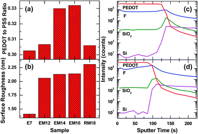
The ratio of the S 2p3/2 peak areas for PEDOT to PSS and its variation with the addition of co-solvents is summarized in Fig. 3a. The E7 film shows a PEDOT to PSS surface composition ratio of ∼0.30, while an increase in the PEDOT to PSS surface composition ratio to ∼0.33 is found for the EM14 and EM16 films. A lower (EM12) or higher (EM18) amount of mixed co-solvent in PEDOT:PSS shows only a slight increase in the ratio (∼0.31). The surface roughness parameters estimated from the respective AFM images are compared in Fig. 3b, which shows an increase in surface roughness from 1.48 nm for E7 to above 2 nm for PEDOT:PSS films with the addition of 12 wt% and more mixed co-solvents. The higher surface roughness of the latter films could also account for the higher antireflective properties found for these films. Using an Ar-cluster sputtering source to remove the polymer films layer-by-layer with minimal near-surface damage, we obtain the depth profiles of chemical-specific moieties (C8H7SO3− ions for the PEDOT component, F− ions for the surfactant, SiO2− ions for the interface oxide layer, and Si− ions for the Si substrate) in the E7 and EM16 films on Si substrates by TOF-SIMS. Both E7 and EM16 films exhibit similar chemical depth profiles, except for a shorter sputtering time to reach the polymer–Si interface of the EM16 sample. Both samples exhibit similarly sharp interface regions. The fluorine signal from the surfactant in the E7 film shows higher amounts at the surface and the interface and a more uniform distribution in the bulk region. For the EM16 sample, a gradual decrease of the F signal from the interface to the near-surface region is observed. The thickness variation, as indicated by the different amounts of sputtering time required to reach the interface, for these samples is in agreement with the results deduced from UV reflectance spectroscopy (Fig. S6, ESI†), which also confirm a thinner EM16 film.
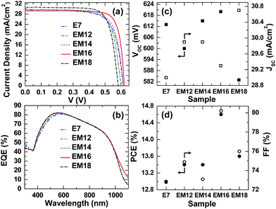
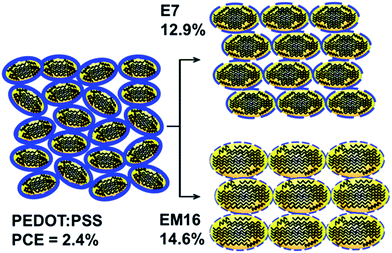
The presence of a thin interfacial silicon oxide layer formed under ambient conditions on the H-terminated Si substrate is beneficial for enhancing the hybrid solar cell properties,14 the thickness of which has been appropriately optimized prior to the spin coating of co-solvent added PEDOT:PSS (Fig. S1 and S2, ESI†). The effects of the oxide layer growth time on the amount of micropore defects and subsequently the solar cell properties are illustrated for the E7 and EM16 cells. A reduced amount of micropore defects14 and/or filling of the micropores by methanol found in the mixed co-solvent added PEDOT:PSS (EM16) lead to an improved PCE. These effects could improve the interface charge transfer process in the EM samples and also reduce the overall cell fabrication time. Fig. 4a and b show the current density vs. voltage (J–V) curves and external quantum efficiency (EQE) spectra of the hybrid solar cells fabricated based on the E7 and EM films. Their corresponding major solar cell performance parameters are compared in Fig. 4c and d (see Table S1, ESI†). All these solar cells measured in the dark showed typical diode characteristics. The cells made of mixed co-solvent added PEDOT:PSS films show significantly higher PCEs than the E7 cell. Our earlier report showed that the PCE of the solar cell made of pristine PEDOT:PSS could only reach 2.4%.7 In contrast, the E7 cell shows a PCE of 12.9% and a Voc of 600 mV, while the highest PCE of 14.6% and Voc of 620 mV are obtained for the EM16 cell. This is the highest efficiency ever reported for a planar single junction hybrid solar cell to date. Similar high Voc and PCE values were achieved for the other set of EM16 samples prepared (Table S2, ESI†). For comparison, solar cells were prepared using 7 wt% and 16 wt% MeOH added PEDOT:PSS. However, these cells showed a poor PCE of below 5% only. It is clear that the structural modification carried out for the mixed co-solvent added PEDOT:PSS films results in the lower resistance values and higher antireflective properties, which in turn improve the carrier collection and solar cell performance.
Based on these results, a schematic model is proposed to represent the modification of PEDOT grains and PSS outer shells as a result of the addition of mixed co-solvent in PEDOT:PSS in comparison with that of EG in PEDOT:PSS (Fig. 5). The pristine PEDOT:PSS is mostly composed of an irregular network of PEDOT and a thicker layer of PSS chains. The ellipsoidal PEDOT grains in the E7 sample are mostly covered with a thinner layer of PSS in comparison to pristine PEDOT:PSS. The excess PSS in the matrix is possibly segregating to the voids between the grain boundaries. A further reduction in the thickness of the PSS layer covering the PEDOT grains occurs with addition of the mixed co-solvent in PEDOT:PSS. Co-solvent addition is also known to induce a rearrangement of the PEDOT chains, from the coil-like benzoid structure that may be present along the grain boundaries to a more linear or extended quinoid structure.3,7,20,22 This structural modification increases the PEDOT size and also promotes closer packing of the PEDOT grains. The mixed co-solvent addition of PEDOT:PSS further facilitates this process by producing thinner PSS covering on the PEDOT grains and further extending the linear chain networks of the quinoid components in the PEDOT grains.10,22 As PSS is insulating in nature, a thinner PSS layer could enhance the bulk conductivity and lead to the observed low sheet resistance. The close packing of PEDOT grains due to mixed co-solvent addition in PEDOT:PSS causes a slight increase in the surface roughness, and facilitates higher transmittance and antireflectance. Filling the interfacial micropore defects by MeOH in the mixed co-solvent could enhance the charge carrier transport, while the closely packed domains in the formation of PEDOT nanocrystals could also suppress the interface defect generation,14 both of which result in the observed higher device performance. As MeOH is known to remove PSS from the film surface during post-treatment,11 removal of the PSS during the spin coating process is enhanced by the MeOH co-solvent, while the EG co-solvent in the PEDOT:PSS film promotes the PSS separation from the PEDOT grains. A larger amount of PSS in the PEDOT:PSS matrix could therefore be spun away from the mixed co-solvent added solution, when compared to the EG added PEDOT:PSS solution during spin coating. This also reduces the overall thickness of the mixed co-solvent modified PEDOT:PSS film as well.
Conclusions
In summary, engineering of PEDOT:PSS by mixed co-solvent addition of an appropriate amount is extremely beneficial for modifying the bulk and structural properties that lead to the low sheet resistance films. The 16 wt% mixed co-solvent added PEDOT:PSS film provides a very high Voc of 620 mV and the highest PCE performance (14.6%) reported to date for a PEDOT:PSS/planar-Si single junction solar cell. This remarkable performance is made possible by the partial removal of the PSS chain network around the grain boundaries of PEDOT, the extended linear chain network of the quinoid structure that results in the enlargement of PEDOT grains, and the improved close packing of PEDOT grains by the mixed co-solvent, which are consistent with the observed reduction in the sheet resistance. Post-treatment could be used to further reduce the surface resistivity of these films. Mixed co-solvent engineering therefore promises a facile approach to produce highly conducting PEDOT:PSS films not just for solar cell applications but indeed for other organic electronic device fabrication.Acknowledgements
This work was supported by the Natural Sciences and Engineering Research Council of Canada.Notes and references
- O. Bubnova, Z. U. Khan, H. Wang, S. Braun, D. R. Evans, M. Fabretto, P. Hojati-Talemi, D. Dagnelund, J. B. Arlin, Y. H. Geerts, S. Desbief, D. W. Breiby, J. W. Andreasen, R. Lazzaroni, W. M. Chen, I. Zozoulenko, M. Fahlman, P. J. Murphy, M. Berggren and X. Crispin, Nat. Mater., 2014, 13, 190–194 CrossRef CAS PubMed; A. Ugur, F. Katmis, M. Li, L. Wu, Y. Zhu, K. K. Varanasi and K. K. Gleason, Adv. Mater., 2015, 27, 4604–4610 CrossRef PubMed.
- Y. Zhang, W. Cui, Y. Zhu, F. Zu, L. Liao, S. T. Lee and B. Sun, Energy Environ. Sci., 2015, 8, 297 Search PubMed; Y. Liu, Z. Zhang, Z. Xia, J. Zhang, Y. Liu, F. Liang, Y. Li, T. Song, X. Yu, S. Lee and B. Sun, ACS Nano, 2016, 10, 704–712 CrossRef CAS PubMed.
- J. Ouyang, Displays, 2013, 34, 423–436 CrossRef CAS; C. M. Palumbiny, C. Heller, C. J. Schaffer, V. Korstgens, G. Santoro, S. V. Roth and P. Muller-Buschbaum, J. Phys. Chem. C, 2014, 118, 13598–13606 Search PubMed; Q. Wei, M. Mukaida, Y. Naitoh and T. Ishida, Adv. Mater., 2013, 25, 2831–2836 CrossRef PubMed.
- Y. Xia, K. Sun and J. Ouyang, Adv. Mater., 2012, 24, 2436–2440 CrossRef CAS PubMed.
- W. Zhang, B. Zhao, Z. He, X. Zhao, H. Wang, S. Yang, H. Wu and Y. Cao, Energy Environ. Sci., 2013, 6, 1956–1964 Search PubMed; J. He, P. Gao, M. Liao, X. Yang, Z. Ying, S. Zhou, J. Ye and Y. Cui, ACS Nano, 2015, 9, 6522–6531 CrossRef CAS PubMed.
- J. Y. Kim, J. H. Jung, D. E. Lee and J. Joo, Synth. Met., 2002, 126, 311–316 CrossRef CAS.
- J. P. Thomas, L. Zhao, D. McGillivray and K. T. Leung, J. Mater. Chem. A, 2014, 2, 2383–2389 CAS.
- C. Badre, L. Marquant, A. M. Alsayed and L. A. Hough, Adv. Funct. Mater., 2012, 22, 2723–2727 CrossRef CAS.
- J. Wang, H. Wang, A. B. Prakoso, A. S. Togonal, L. Hong, C. Jiang and Rusli, Nanoscale, 2015, 7, 4559–4565 CAS.
- N. Kim, S. Kee, S. H. Lee, B. H. Lee, Y. H. Kahng, Y. R. Jo, B. J. Kim and K. Lee, Adv. Mater., 2014, 26, 2268–2272 CrossRef CAS PubMed.
- D. Alemu, H. Y. Wei, K. C. Ho and C. W. Chu, Energy Environ. Sci., 2012, 5, 9662–9671 CAS.
- H. Jeong, H. Song, Y. Pak, I. K. Kwon, K. Jo, H. Lee and G. Y. Jung, Adv. Mater., 2014, 26, 3445–3450 CrossRef CAS PubMed.
- Q. Liu, R. Ishikawa, S. Funada, T. Ohki, K. Ueno and H. Shirai, Adv. Energy Mater., 2015, 5, 1500744 CrossRef.
- J. P. Thomas and K. T. Leung, Adv. Funct. Mater., 2014, 24, 4978–4985 CrossRef CAS.
- L. He, D. Lai, H. Wang, C. Jiang and Rusli, Small, 2012, 8, 1664–1668 CrossRef CAS PubMed.
- P. Yu, C. Y. Tsai, J. K. Chang, C. C. Lai, P. H. Chen, Y. C. Lai, P. T. Tsai, M. C. Li, H. T. Pan, Y. Y. Huang, C. I. Wu, Y. L. Chueh, S. W. Chen, C. H. Du, S. F. Horng and H. F. Meng, ACS Nano, 2013, 7, 10780–10787 CrossRef CAS PubMed.
- Y. Xia, K. Sun and J. Ouyang, Adv. Mater., 2012, 24, 2436–2440 CrossRef CAS PubMed.
- W. W. Chiu, J. Travaš-Sejdić, R. P. Cooney and G. A. Bowmaker, J. Raman Spectrosc., 2006, 37, 1354–1361 CrossRef CAS.
- A. Schaarschmidt, A. A. Farah, A. Aby and A. S. Helmy, J. Phys. Chem. B, 2009, 113, 9352–9355 CrossRef CAS PubMed.
- M. Lapkowski and A. Pron, Synth. Met., 2000, 110, 79–83 CrossRef CAS.
- X. Crispin, F. L. E. Jakobsson, A. Crispin, P. C. M. Grim, P. Andersson, A. Volodin, C. V Haesendonck, M. V. D. Auweraer, W. R. Salaneck and M. Berggren, Chem. Mater., 2006, 18, 4354–4360 CrossRef CAS.
- J. P. Thomas, S. Srivastava, L. Zhao, M. Abd-Ellah, D. McGillivray, J. S. Kang, M. A. Rahman, N. Moghimi, N. F. Heinig and K. T. Leung, ACS Appl. Mater. Interfaces, 2015, 7, 7466–7470 CAS.
Footnote |
| † Electronic supplementary information (ESI) available. See DOI: 10.1039/c6ta07410c |
| This journal is © The Royal Society of Chemistry 2016 |

