 Open Access Article
Creative Commons Attribution 3.0 Unported Licence
Effect of coatings on the green electrode processing and cycling behaviour of LiCoPO4†
Nina
Laszczynski
abc,
Agnese
Birrozzi
ab,
Krzysztof
Maranski
d,
Mark
Copley
d,
Manfred Erwin
Schuster
d and
Stefano
Passerini
 *ab
*ab
aHelmholtz Institute Ulm (HIU), Helmholtzstr. 11, 89081, Ulm, Germany
bKarlsruhe Institute of Technology (KIT), P. O. Box 3640, 76021 Karlsruhe, Germany. E-mail: stefano.passerini@kit.edu
cInstitute of Physical Chemistry, University of Muenster, Corrensstr. 28/30, 48149 Muenster, Germany
dJohnson Matthey Technology Centre, Blount's Court Road, Sonning Common, Reading, RG4 9NH, UK
First published on 11th October 2016
Abstract
Several approaches involving carbon and VOx coatings of LiCoPO4 to enable aqueous electrode processing are reported in this manuscript along with detailed physico-chemical and electrochemical investigations. It is shown that the choice of the carbon source has a severe impact not only on the purity, particle size and morphology of LiCoPO4, but also on its electrochemical performance. Although carbon coating improves the conductivity of LiCoPO4 and protects the particles' surface from direct contact with the electrolyte, it also leads to capacity fading upon cycling at high potentials. Reducing the carbon amount leads to an initially reduced capacity, but it significantly improves the stability upon cycling. Finally, the application of an additional VOx coating was also investigated.
Introduction
Nowadays, “4 V” cathode materials, e.g., LiFePO4, LiMn2O4, LiCoO2 or LiNi1/3Co1/3Mn1/3O2, are used in commercial Li-ion batteries for small electronic devices as well as hybrid (HEV) and full (FEV) electric vehicles.1–3 However, higher cell potentials are required in order to achieve the energy and power densities needed, especially, for electric vehicles. Toward such a target, the family of olivines is in the focus of research. In particular, LiNiPO4 (LNP) and LiCoPO4 (LCP), offering working potentials above 5 V and around 4.8 V, respectively, and theoretical specific capacities above 165 mA h g−1, are under consideration. Besides the theoretical energy performance, olivines show the advantage of superior safety among other cathode materials due to the covalent P–O bonds of the highly stable PO4 units. These bonds do not result in oxygen release upon heating, thus sharply reducing the risk of cell thermal runaway.4,5 However, olivines suffer from low electronic conductivity which is well known for LiFePO4 (LFP); thus this issue has been deeply investigated and solved for LFP. Decreasing the particle size to the nanoscale, i.e., reducing the length of the electronic paths, and applying a carbon coating increase the overall electronic conductivity in and among LFP particles.6 The same approach is, in theory, suitable for LCP and LNP as well. However, concerns exist about the stability of carbon at elevated potentials. In fact, conductive carbons (i.e., the carbon added into composite electrodes to enhance their overall electronic conductivity) were reported to suffer from oxidation and reaction with the electrolyte.7Aside from the active material choice, electrode processing is an important factor for the production of Li-ion batteries for commercial devices where cost and environmental impact are among the main requirements. Aqueous processing not only is environmentally benign because no volatile organic solvents need to be used, but is also more cost efficient since the binder itself is cheaper than polyvinylidene fluoride (PVdF), the most commonly used binder for LIB cathodes and, moreover, the costly recovery of (toxic) N-methyl-pyrrolidone (NMP) can be avoided.8–10 Since sodium carboxymethylcellulose (CMC) has been proven as an effective binder for carbon coated LFP, it has been investigated herein for LCP electrodes.11–13
Within this work the application of carbon coatings from different precursors as well as of an additional VOx coating onto LCP nanoparticles is investigated with respect to the aqueous processing of such materials into electrodes. Three different carbon sources were used, namely, sucrose, polyacrylic acid (PAA) and polyoxyethylene (20)-sorbitan-monooleate (Tween 80®). While the first material shows a relatively low decomposition temperature (easy to carbonize), the second shows a chelating behavior and is known to protect metals from corrosion.14,15 The third precursor is a derivative of oleic acid, bearing a ring structure that was shown to improve the cycling stability of LFP.16 Following a different approach, the application of an additional vanadium oxide coating, starting from the crystalline layer of V2O5 as a precursor, was investigated. The coating is referred as VOx to indicate that the nature of the material might have been partially changed from the starting V2O5. In fact, it was impossible to determine exactly the oxidation state and the structure of the vanadium phase since the coated sample appeared to be susceptible to the TEM electron beam, thus complicating data interpretation. Although VOx is not a good electronic conductor, a very thin layer of VOx on the particle surface of Li2MnO3·LiMO2 (M = Ni, Mn, Co), also operating above 4.5 V, was shown to significantly enhance the capacity and cycling performance.17
As shown later in this manuscript, the carbon coating enhances significantly the conductivity of LCP electrodes which, therefore, deliver higher capacities. However, such electrodes still suffer from significant fading upon cycling, thus offering poor capacity retention. The VOx coating, instead, reduces overall the active materials' specific capacity.
Experimental
Synthesis and coating of LiCoPO4
A precursor of LCP was synthesized at the Johnson Matthey Technology Centre by flame spray pyrolysis. In summary, the synthesis involves the preparation of a precursor solution containing Li, Co and P species dissolved in organic solvents. Igniting the sprayed solution (in an aerobic environment) results in the formation of nanoparticles, which were collected for further processing. Prior to calcination different coating precursors were applied on the LCP precursor, namely, those based on carbon and vanadium.For the carbon coating, sucrose (LCP/C1 and LCP/C2) and polyacrylic acid (LCP/C3) were dissolved in ultrapure water (MilliQ). To these solutions, an appropriate amount of LCP precursor was added in order to obtain sucrose![[thin space (1/6-em)]](https://www.rsc.org/images/entities/char_2009.gif) :
:![[thin space (1/6-em)]](https://www.rsc.org/images/entities/char_2009.gif) LCP weight ratios of 0.2 and 0.1 and a PAA
LCP weight ratios of 0.2 and 0.1 and a PAA![[thin space (1/6-em)]](https://www.rsc.org/images/entities/char_2009.gif) :
:![[thin space (1/6-em)]](https://www.rsc.org/images/entities/char_2009.gif) LCP weight ratio of 0.2. The resulting slurries were mixed for 2 h at 400 rpm using a planetary ball mill (Vario-Planetary Mill Pulverisette 4, Fritsch).14 The slurries were dried at 60 °C for 12 h and ground afterwards. When using polyoxyethylene (20)-sorbitan-monooleate (Tween 80®, Merck Millipore) as the carbon source (LCP/C4), the precursor of LCP was added to an aqueous solution of Tween 80® (weight ratio 0.4) and the resulting slurry was mixed for 8 h at 400 rpm using a planetary ball mill. After drying, the mixture was milled again at 400 rpm for 12 h and ground in a mortar.16 The mixtures were then calcined at 700 °C for 2 h in a tubular furnace under an Ar atmosphere. For comparison purposes, a reference material was made from the LCP precursor by calcination, hereafter referred to as pristine LCP.
LCP weight ratio of 0.2. The resulting slurries were mixed for 2 h at 400 rpm using a planetary ball mill (Vario-Planetary Mill Pulverisette 4, Fritsch).14 The slurries were dried at 60 °C for 12 h and ground afterwards. When using polyoxyethylene (20)-sorbitan-monooleate (Tween 80®, Merck Millipore) as the carbon source (LCP/C4), the precursor of LCP was added to an aqueous solution of Tween 80® (weight ratio 0.4) and the resulting slurry was mixed for 8 h at 400 rpm using a planetary ball mill. After drying, the mixture was milled again at 400 rpm for 12 h and ground in a mortar.16 The mixtures were then calcined at 700 °C for 2 h in a tubular furnace under an Ar atmosphere. For comparison purposes, a reference material was made from the LCP precursor by calcination, hereafter referred to as pristine LCP.
The VOx coating (LCP/V) was applied on previously carbon-coated LCP particles to prevent their degradation. In fact, while LCP needs to be calcined at elevated temperatures in an inert atmosphere (700 °C in Ar), VOx crystallizes already at 350 °C, but it requires an ambient or oxidative atmosphere. Thus, the interposition of a protecting layer was necessary to prevent LCP oxidation during the crystallization of the VOx layer. Thus, the LCP precursor was first coated with carbon using sucrose as the carbon source (as shown later in this manuscript). Then, the VOx coating was applied as described previously.17 A V2O5 hydrogel was synthesized by dispersing crystalline V2O5 (Pechiney) in an aqueous solution of H2O2 (weight ratio of V2O5![[thin space (1/6-em)]](https://www.rsc.org/images/entities/char_2009.gif) :
:![[thin space (1/6-em)]](https://www.rsc.org/images/entities/char_2009.gif) H2O2 = 1
H2O2 = 1![[thin space (1/6-em)]](https://www.rsc.org/images/entities/char_2009.gif) :
:![[thin space (1/6-em)]](https://www.rsc.org/images/entities/char_2009.gif) 10) by stirring for 10 min at 0 °C. Carbon coated LCP was added (weight ratio of LCP
10) by stirring for 10 min at 0 °C. Carbon coated LCP was added (weight ratio of LCP![[thin space (1/6-em)]](https://www.rsc.org/images/entities/char_2009.gif) :
:![[thin space (1/6-em)]](https://www.rsc.org/images/entities/char_2009.gif) V2O5 = 0.97
V2O5 = 0.97![[thin space (1/6-em)]](https://www.rsc.org/images/entities/char_2009.gif) :
:![[thin space (1/6-em)]](https://www.rsc.org/images/entities/char_2009.gif) 0.03) and afterwards the dispersion was mixed for 3 h at room temperature by magnetic stirring at 300 rpm. After drying and grinding, the powder mixtures were recalcined at 350 °C for 5 h in a box furnace. Upon this latter step the carbon layer vanished completely as confirmed by C/H/N analysis.
0.03) and afterwards the dispersion was mixed for 3 h at room temperature by magnetic stirring at 300 rpm. After drying and grinding, the powder mixtures were recalcined at 350 °C for 5 h in a box furnace. Upon this latter step the carbon layer vanished completely as confirmed by C/H/N analysis.
Physico-chemical investigation of coated and uncoated LiCoPO4
Powder X-ray diffraction patterns were recorded between 10 and 78° (2θ) with a step size of 0.011278° on a Bruker D8 Advance diffractometer with a Cu-Kα source (λ = 0.154 nm). Thermogravimetric analysis in nitrogen and oxygen atmospheres of LCP before and after calcination was performed with a Discovery TGA (TA-Instruments). The samples were heated up to 700 °C with a heating rate of 5 °C min−1. Elemental analysis (C/H/N analysis) was performed on a Vario Micro cube. The materials as well as the electrodes were characterized by high resolution scanning electron microscopy (SEM, Zeiss LEO 1550).Transmission electron microscopy (TEM) was performed on an aberration-corrected JEOL-JEM2100 Microscope operated at 200 kV. The ground powder was dispersed directly onto a holey carbon coated Cu TEM grid.
Electrode making and cell assembly
Composite electrodes were made of 85 wt% active material, 10 wt% conductive carbon (C-Nergy, Super C45, Imerys) and 5 wt% binder (CMC, DOW Wolff Celulosics, Walocel CRT2000 PA12). The CMC binder was first dissolved in ultrapure water by magnetic stirring for 12 h at 300 rpm. Conductive carbon was added to the solution and dispersed by magnetic stirring for an additional 3 h. The active material was added and further mixed by magnetic stirring for 2 h, followed by high speed mixing at 5000 rpm for 10 min. All slurries were cast immediately onto aluminum current collectors using a laboratory doctor blade coater.8 Disc electrodes (1.13 cm2, active material mass loading: 1.3 to 2.0 mg cm−2 for pristine LCP and LCP/C1 (sucrose as the carbon precursor), LCP/C2 (sucrose as the carbon precursor), LCP/C4 (Tween 80® as the carbon precursor) and LCP/V (V2O5 as the coating precursor); 3.8 mg cm−2 for LCP/C3 (polyacrylic acid as the carbon precursor)) were punched, pressed at 4 tons for 1 min and dried at 120 °C under vacuum for 12 h.Cells were assembled in a three-electrode configuration in an Ar filled dry-box (MBraun, H2O and O2 contents <1 ppm) with lithium metal foil (Rockwood Lithium) as the counter and reference electrodes. A glass fiber felt (Whatman®, GF/D) was used as the separator, which was soaked in an electrolyte solution of 1 M LiPF6 in 1![[thin space (1/6-em)]](https://www.rsc.org/images/entities/char_2009.gif) :
:![[thin space (1/6-em)]](https://www.rsc.org/images/entities/char_2009.gif) 1 (wt) EC/DMC (UBE).
1 (wt) EC/DMC (UBE).
Electrochemical testing of coated and uncoated LiCoPO4 electrodes
The electrochemical performance of the active materials was evaluated by subjecting the corresponding electrodes to galvanostatic cycle tests within 5.0 V and 4.0 V cut-off limits using a Maccor series 4000 battery tester. The testing protocol involved five cycles at charge/discharge current rates of C/10 followed by 100 cycles at a 1C rate. Finally, a set of five cycles at C/10 was repeated to verify the capacity retention. A material nominal capacity of 167 mA h g−1 was used to calculate the current density at the various rates.Electrochemical impedance spectroscopy (EIS) measurements (frequency range from 500 kHz to 15 mHz, sinusoidal amplitude 10 mV) were performed on the cells after cycling (see the cycling test above) using an AMETEK® ModuLab XM.
Results and discussion
Physico-chemical investigation of coated and uncoated LiCoPO4
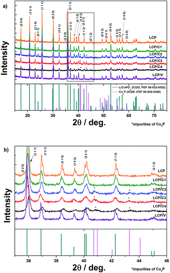
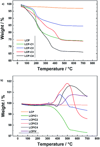
Fig. 1a shows the XRD patterns of pristine, carbon-coated and VOx-coated LCP. Rietveld refinement of all samples (Rwp between 3.89 and 5.36) (Bruker, TOPAS 4.2) was performed. The lattice parameters of all the coated samples are in good agreement with those of pristine LCP. For LCP/C2, LCP/C3 and LCP/C4 additional reflections of Co2P are visible between 2θ angles of 40 and 44° (Fig. 1b).Co2P usually appears as an impurity phase upon synthesis and/or further processing of LiCoPO4, e.g., calcination in the presence of a carbon source in an inert atmosphere, due to the surface reduction of LCP.18,19 A dependence of the Co2P content using different coatings has been observed. In fact, LCP, LCP/C1 and LCP/V materials were almost phase pure, while LCP/C2, LCP/C3 and LCP/C4 showed Co2P contents between 3 and 4% (see Table 1). However, it can be pointed out that even if a small but variable percentage of Co2P phase impurity was detected, the various coating processes had no major effect on the LCP crystal structure.20 Thermogravimetric analysis of the calcined pristine LCP, carbon-coated LCP materials (before and after calcination) and VOx-coated LCP (after calcination) was performed. The TGA curves of LCP materials coated with carbon precursors before calcination are compared with those of the pristine LCP precursor in Fig. 2a. While only a minor weight loss was observed for the pristine LCP precursor, the coated samples showed the weight loss typical of the coating carbonization along with the initial weight loss due to residual water.15,21 Under an inert atmosphere and in the presence of LCP, sucrose sharply decomposes at about 190 °C, but the carbonization process is completed only at temperatures near 500 °C. On the other hand, PAA and the oleic acid derivative (Tween 80) showed continuous decomposition (partially overlapping with the initial water release) ending at lower temperatures, but still higher than 400 °C (ESI Fig. S1†).15,21
| LCP | C1 | C2 | C3 | C4 | V | |
|---|---|---|---|---|---|---|
| a Lattice parameters and phase ratios were determined using the program TOPAS 4-2 (see also, ESI Table S1). | ||||||
| Coating source | — | Sucrose | Sucrose | PAA | Tween 80® | V2O5 |
| Source vs. LCP in wt% | — | 20 | 10 | 20 | 40 | 3 |
![[thin space (1/6-em)]](https://www.rsc.org/images/entities/char_2009.gif) |
||||||
| C/H/N analysis | ||||||
| C-content in wt% | — | 2.6 | 2.0 | 3.2 | 1.8 | 0 |
![[thin space (1/6-em)]](https://www.rsc.org/images/entities/char_2009.gif) |
||||||
| XRD investigation | ||||||
| a (Å) | 10.2069(3) | 10.2064(4) | 10.2052(3) | 10.2005(5) | 10.2061(6) | 10.2054(2) |
| b (Å) | 5.9231(2) | 5.9229(2) | 5.9242(2) | 5.9328(3) | 5.9313(3) | 5.9221(1) |
| c (Å) | 4.7011(2) | 4.7006(2) | 4.7011(2) | 4.7043(3) | 4.7049(3) | 4.7004(1) |
| Phase ratio of Co2P impurity in % | 0.3(2) | 0.4(2) | 2.6(2) | 3.4(2) | 4.1(2) | 0.2(2) |
| R wp | 4.80 | 5.36 | 3.89 | 4.25 | 4.46 | 4.96 |
The characterization of the calcined uncoated and coated materials in an O2 atmosphere is presented in Fig. 2b. At higher temperatures, two different and contrasting phenomena take place, which are the weight loss due to the reaction of the carbon coating with oxygen and the weight increase due to the oxidation of the Co2P phase and/or the VOx coating (around 400–500 °C). These results are in very good agreement with the results obtained from XRD measurements. The materials showing higher amounts of Co2P impurity phase in the XRD pattern also show an increase in weight around 400 to 500 °C related to the reaction of the Co2P phase with oxygen.18,22 The weight increase observed for the VOx-coated LCP (LCP/V) is associated with the oxidation of vanadium, indicating that the latter is partially reduced during the crystallization process at 350 °C.23
Since the overlapping of the carbon coating combustion with the Co2P oxidation did not make it possible to determine the carbon content of the various coatings by TGA, C/H/N analysis was performed. The results (see Table 1) showed that all carbon-coated samples had a carbon content below 4 wt%. For example, using 20 wt% of polyacrylic acid as the carbon source (C3) resulted in the highest carbon content (3.2 wt%) while 20 wt% sucrose (C1) led to only 2.6 wt% of C. However, reducing the amount of sucrose to 10 wt% (C2) resulted in a non-linear decrease of carbon (2.0 wt%). In spite of its large content (40 wt% with respect to the weight of LCP) Tween 80® led only to 1.8 wt% of carbon coating. Finally, C/H/N analysis of sample LCP/V demonstrated that the coating process of vanadium oxide led to the full removal of the preliminary carbon coating.
Fig. 3 shows the SEM images of coated and uncoated LCP samples, whose particle sizes were seen to vary between 50 and 300 nm. Sucrose as the source for the carbon coating resulted in thin layers on the particle surface (Fig. 3a and b), samples LCP/C1 and LCP/C2, while for both PAA (Fig. 3c, sample LCP/C3) and Tween 80® (Fig. 3d, sample LCP/C4) a thick film was visible, probably due to their incomplete degradation. For these latter samples an inhomogeneous distribution of particle aggregates was also observed. Regarding the VOx-coated material no film was observed in the SEM image (Fig. 3e, sample LCP/V), but small VOx particles lying on the surface of the LCP particles were detected. Nevertheless, TEM investigations (Fig. 4e) showed the formation of a homogeneous, but rather thick VOx surface layer (up to 8 nm thick) on the LCP particles. The same is true for LCP/C1, which showed (Fig. 4a) a homogeneous coating layer with a well-defined thickness of about 3 nm. LCP/C2 (Fig. 4b) showed a carbon layer on the entire surface; however, it is not homogeneous in thickness, whereas LCP/C3 and LCP/C4 (Fig. 4c and d, respectively) showed partially uncoated areas. These observations were confirmed by EDX line scan measurements (ESI Fig. S2†). Additionally, SEM images of the electrode surface were taken, and are described briefly in the ESI (Fig. S3†).
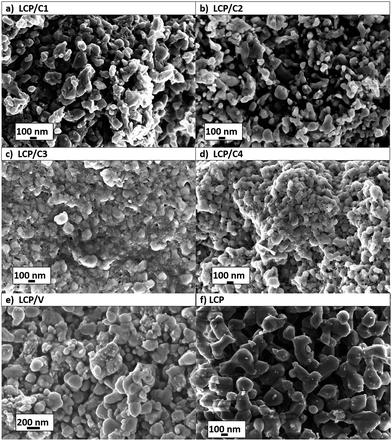 | ||
| Fig. 3 SEM of pristine and coated LCP powders. (a) 20 wt% sucrose, (b) 10 wt% sucrose, (c) 20 wt% polyacrylic acid, (d) 40 wt% Tween 80®, (e) 3 wt% V2O5, and (f) pristine LCP. | ||
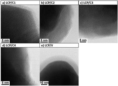 | ||
| Fig. 4 TEM images of coated LCP particles. (a) 20 wt% sucrose, (b) 10 wt% sucrose, (c) 20 wt% polyacrylic acid, (d) 40 wt% Tween 80®, and (e) 3 wt% V2O5. | ||
Electrochemical investigation of pristine and coated LCP electrodes
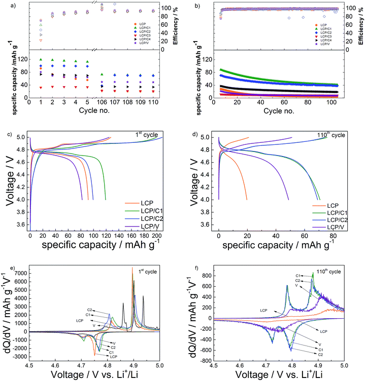
The results of the long-term galvanostatic cycling of pristine and coated LCP electrodes are shown in Fig. 5a and b. Materials LCP/C3 and LCP/C4 were excluded from deeper electrochemical studies because of the incomplete coating leading to substantial capacity fading (see Fig. 4).Upon charging all electrodes showed two plateaus during the first charge (Fig. 5c) associated with the two-step Li+-deinsertion mechanism,24,25 which is better evidenced by the two peaks appearing in the differential capacity plot (Fig. 5e). The first plateau, occurring between 4.80 and 4.86 V, involves the extraction of about 0.3 eq. of Li+, while the second one (between 4.88 and 4.93 V) is associated with the full delithiation of the active material, theoretically leading to CoPO4.24,26,27 However, the charge specific capacities of LCP/C1 and LCP/C2 (both coatings using sucrose as the carbon source) are well above the theoretical value. Such an extraordinary capacity is certainly associated with electrolyte decomposition rather than the oxidation of the carbon coating because of the quite low amount of carbon in the coating (see Table 1).7 However, the carbon coating is certainly playing a role in increasing the electrode conductivity and the electrolyte/electrode contact area, thus even favoring the electrolyte decomposition. The VOx-coated material, on the other hand, showed a delithiation behavior similar to that of pristine LCP.
Upon the first discharge, however, electrodes of LCP/C1 and LCP/C2 performed better than the other two materials. This is in agreement not only with the higher delithiation level, but also with the very low amounts of phase impurities and complete surface coating of the LCP particles (see XRD and TEM results). During the first cycle (C/10 rate) LCP/C1 and LCP/C2 delivered discharge capacities of 120 and 100 mA h g−1, respectively, whereas pristine LCP only achieved 90 mA h g−1. Once more, the VOx-coated material showed similar performance to pristine LCP (slightly more than 80 mA h g−1).
Upon discharge, however, all electrodes showed much lower capacities than those observed during the first charge. As mentioned earlier, such an irreversible behavior is associated not only with the degradation of the electrolyte, but also with the nucleophilic attack of F− on phosphorus atoms destroying P–O bonds and therefore, damaging the olivine structure.28 The carbon-coated materials (LCP/C1 and LCP/C2) displayed the highest first cycle irreversible capacity as a result of the massive electrolyte decomposition discussed above. However, in the following low rate (C/10) cycles these two materials showed rapidly improving reversibility. As well the VOx-coated material showed faster improvement than pristine LCP.
With respect to the capacity retention of the active materials, pristine LCP showed, among all, the fastest capacity fading upon the initial low rate (C/10) cycles, indicating that any of the coating had some beneficial effect on the capacity retention. Nevertheless, it is important to notice that the electrolyte decomposition occurring in the initial cycles for all electrodes may lead to the formation of a layer, usually called the Solid Electrolyte Interface (SEI), as observed for LCP and other high voltage electrodes.29–31
Upon long-term, high rate cycling (Fig. 5b) all materials show performance fading. In particular, the VOx-coated (LCP/V) and pristine LCP electrodes' specific capacities decreased to or even below 10 mA h g−1 within a few cycles. On the other hand, LCP/C1 and LCP/C2 showed still appreciable delivered capacities (about 40 mA h g−1) after 100 cycles at 1C. This resulted from the better capacity retention of the LCP/C2 electrode. In fact, while LCP/C1 showed the highest initial capacity, both at C/10 and 1C, LCP/C2 showed better capacity retention (62% for LCP/C1 and 70% for LCP/C2 comparing the 5th (Fig. S4†) and the 112th cycle). After 100 cycles, LCP/C1 and LCP/C2 showed a very similar performance at a C/10 rate, showing also very similar differential capacity and voltage profiles. Overall, the uniform carbon coating obtained by using sucrose is certainly protecting the active material from reactions due to electrolyte decomposition.
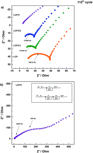
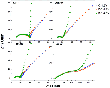
In order to better understand the reason for the different performances of the materials upon cycling, electrochemical impedance spectroscopy measurements were performed on cycled cells. In particular, after the standard long-term cycling test, the cell was charged to 5 V and immediately discharged to 4.8 V and held for two hours at that potential prior to performing the EIS measurements. Fig. 6 shows the Nyquist plots of LCP, LCP/C1, LCP/C2 and LCP/V electrodes recorded at a constant potential of 4.8 V. The LCP and LCP/C1 electrodes were subjected to a further discharge and charge cycle during which EIS measurements (Fig. 7) were taken at different voltages (after 2 hour potentiostatic equilibration).
The Nyquist plots in Fig. 6a all show a semicircle associated with the electrode/electrolyte interface, followed by an almost straight line associated with diffusion-limited processes occurring in the bulk of the electrodes. For all electrodes, the high to medium frequency semicircle appears to be strongly depressed, which is expected considering that it reflects both the charge transfer and the SEI impedance. In the case of the VOx-coated LCP electrode, however, two parallel (RC) elements were used to obtain the best fit (inset of Fig. 6b).32–34 The extent of the high frequency feature was strongly affected by the various coatings. In fact, electrodes LCP/C1 and LCP/C2 showed a rather moderate interface resistance, about 50% of the LCP resistance (see Table S2†). On the other hand, the VOx-coated sample showed a large interface resistance (see the expanded plot in Fig. 6b and Table S2†).35,36 Interestingly, for LCP, LCP/C1 and LCP/C2 electrodes a loop at the end of the semicircle was still observed which is indicative of irreversible processing occurring during the measurements at different voltages. This was not the case for the VOx-coated electrode.
Comparing the impedance results of the carbon coated samples after galvanostatic cycling test confirms that LCP/C1 and LCP/C2 show the best performance (Fig. 5 and 7). The overall resistance is reduced significantly in comparison to pristine LCP for both samples. After 112 cycles, the impedance measurements do not show significant differences between LCP/C1 and LCP/C2, confirming the galvanostatic cycling results for these samples. In contrast for LCP/V the overall resistance is significantly higher (420 to 490 Ω) underlining the assumption that the non-conductive coating layer, especially after being exposed to the electrolyte upon cycling, is too thick.
Conclusions
Different carbon and VOx coatings were successfully applied to LCP while maintaining the phase purity of the active material.All coated materials (together with pristine LCP) were processed into electrodes using, for the first time, an aqueous binder. The investigation on the coatings' effect on the electrodes' capacity and cycling stability, performed using a combination of analytical techniques including impedance spectroscopy, showed that the formation of a homogeneous carbon coating enhances both the first cycle capacity (120 mA h g−1) and capacity retention upon cycling. Nevertheless, the typical fading of LCP-based materials, mainly due to the electrolyte decomposition at high operating voltages, is still present. After 112 cycles the carbon-coated LCP electrodes (LCP/C1 and LCP/C2) offered a specific capacity of only 70 mA h g−1. Although the thicker carbon coating (20 wt% of sucrose as the precursor) showed a superior capacity during the first cycles, it also showed a more severe fading upon cycling. Coating the material with VOx, instead, leads to a significant capacity reduction, especially at 1C rate.
Nevertheless, the coating approach appears as a good strategy for increasing the LCP electrode capacity retention upon cycling.
Acknowledgements
The support from the European Commission under the MARS-EV (Grant agreement no. 609201) project is gratefully acknowledged. Imerys and Rockwood Lithium are kindly acknowledged for supplying the C-NERGY Super C45 carbon additive and lithium foil, respectively. Furthermore, the authors would like to thank Dr Jan von Zamory for performing SEM analysis.References
- D. Aurbach, J. Power Sources, 2000, 89, 206–218 CrossRef CAS.
- B. Scrosati and J. Garche, J. Power Sources, 2010, 195, 2419–2430 CrossRef CAS.
- O. K. Park, Y. Cho, S. Lee, H.-C. Yoo, H.-K. Song and J. Cho, Energy Environ. Sci., 2011, 4, 1621–1633 CAS.
- J. Li, S. Jeong, R. Kloepsch, M. Winter and S. Passerini, J. Power Sources, 2013, 239, 490–495 CrossRef CAS.
- C. M. Julien and A. Mauger, Ionics, 2013, 19, 951–988 CrossRef CAS.
- J.-M. Tarascon and M. Armand, Nature, 2001, 414, 359–367 CrossRef CAS PubMed.
- C. A. Michael Metzger, C. Marino, D. Haering, C. Kavakli and H. A. G. Sreeraj Puravankara, T. Nilges and C. Stinner, in 2014 ECS and SMEQ Joint International Meeting, 2014 Search PubMed.
- N. Loeffler, J. von Zamory, N. Laszczynski, I. Doberdo, G.-T. Kim and S. Passerini, J. Power Sources, 2014, 248, 915–922 CrossRef CAS.
- J. Li, C. Daniel and D. Wood, J. Power Sources, 2011, 196, 2452–2460 CrossRef CAS.
- G. Liu, H. Zheng, S. Kim, Y. Deng, A. M. Minor, X. Song and V. S. Battaglia, J. Electrochem. Soc., 2008, 155, A887–A892 CrossRef CAS.
- S. S. Jeong, N. Böckenfeld, A. Balducci, M. Winter and S. Passerini, J. Power Sources, 2012, 199, 331–335 CrossRef CAS.
- S. F. Lux, F. Schappacher, A. Balducci, S. Passerini and M. Winter, J. Electrochem. Soc., 2010, 157, A320–A325 CrossRef CAS.
- L. Qiu, Z. Shao, D. Wang, W. Wang, F. Wang and J. Wang, Carbohydr. Polym., 2014, 111, 588–591 CrossRef CAS PubMed.
- F. Mueller, D. Bresser, E. Paillard, M. Winter and S. Passerini, J. Power Sources, 2013, 236, 87–94 CrossRef CAS.
- Y. Wang, I. Deen and I. Zhitomirsky, J. Colloid Interface Sci., 2011, 362, 367–374 CrossRef CAS PubMed.
- Y.-G. Huang, F.-H. Zheng, X.-H. Zhang, Q.-Y. Li and H.-Q. Wang, Electrochim. Acta, 2014, 130, 740–747 CrossRef CAS.
- N. Laszczynski, J. von Zamory, J. Kalhoff, N. Loeffler, V. S. K. Chakravadhanula and S. Passerini, ChemElectroChem, 2015, 2, 1768–1773 CrossRef CAS.
- J. Wolfenstine, J. Read and J. L. Allen, J. Power Sources, 2007, 163, 1070–1073 CrossRef CAS.
- X. Lin, Y. Zhao, Z. Liang, D. Yan, X. Liu, M. Wen, Y. Dong and Q. Kuang, J. Alloys Compd., 2015, 646, 727–733 CrossRef CAS.
- K. Amine, H. Yasuda and M. Yamachi, Electrochem. Solid-State Lett., 2000, 3, 178–179 CrossRef CAS.
- H. Chen, B. Dou, Y. Song, Y. Xu, Y. Zhang, C. Wang, X. Zhang and C. Tan, Fuel, 2012, 95, 425–430 CrossRef CAS.
- J. Ni, H. Wang, L. Gao and L. Lu, Electrochim. Acta, 2012, 70, 349–354 CrossRef CAS.
- C. Piccirillo, R. Binions and I. P. Parkin, Chem. Vap. Deposition, 2007, 13, 145–151 CrossRef CAS.
- N. N. Bramnik, K. Nikolowski, C. Baehtz, K. G. Bramnik and H. Ehrenberg, Chem. Mater., 2007, 19, 908–915 CrossRef CAS.
- S. Theil, M. Fleischhammer, P. Axmann and M. Wohlfahrt-Mehrens, J. Power Sources, 2013, 222, 72–78 CrossRef CAS.
- N. N. Bramnik, K. G. Bramnik, T. Buhrmester, C. Baehtz, H. Ehrenberg and H. Fuess, J. Solid State Electrochem., 2004, 8, 558–564 CrossRef CAS.
- M. Nakayama, S. Goto, Y. Uchimoto, M. Wakihara and Y. Kitajima, Chem. Mater., 2004, 16, 3399–3401 CrossRef CAS.
- E. Markevich, R. Sharabi, H. Gottlieb, V. Borgel, K. Fridman, G. Salitra, D. Aurbach, G. Semrau, M. A. Schmidt, N. Schall and C. Bruenig, Electrochem. Commun., 2012, 15, 22–25 CrossRef CAS.
- J. Xu, S.-L. Chou, M. Avdeev, M. Sale, H.-K. Liu and S.-X. Dou, Electrochim. Acta, 2013, 88, 865–870 CrossRef CAS.
- M. Xu, N. Tsiouvaras, A. Garsuch, H. A. Gasteiger and B. L. Lucht, J. Phys. Chem. C, 2014, 118, 7363–7368 CAS.
- L. Yang, B. Ravdel and B. L. Lucht, Electrochem. Solid-State Lett., 2010, 13, A95–A97 CrossRef CAS.
- B. Jin, H.-B. Gu and K.-W. Kim, J. Solid State Electrochem., 2008, 12, 105–111 CrossRef CAS.
- J. L. Allen, T. Thompson, J. Sakamoto, C. R. Becker, T. R. Jow and J. Wolfenstine, J. Power Sources, 2014, 254, 204–208 CrossRef CAS.
- J. P. Schmidt, T. Chrobak, M. Ender, J. Illig, D. Klotz and E. Ivers-Tiffée, J. Power Sources, 2011, 196, 5342–5348 CrossRef CAS.
- S.-L. Chou, J.-Z. Wang, J.-Z. Sun, D. Wexler, M. Forsyth, H.-K. Liu, D. R. MacFarlane and S.-X. Dou, Chem. Mater., 2008, 20, 7044–7051 CrossRef CAS.
- C. Leger, S. Bach, P. Soudan and J.-P. Pereira-Ramos, J. Electrochem. Soc., 2005, 152, A236–A241 CrossRef CAS.
Footnote |
| † Electronic supplementary information (ESI) available. See DOI: 10.1039/c6ta05262b |
| This journal is © The Royal Society of Chemistry 2016 |

