
 Open Access Article
 This Open Access Article is licensed under a
 Creative Commons Attribution 3.0 Unported Licence
Understanding why replacing I3−/I− by cobalt(II)/(III) electrolytes in bis(diimine)copper(I)-based dye-sensitized solar cells improves performance†
Sebastian O.
Fürer
,
Biljana
Bozic-Weber
,
Thomas
Schefer
,
Cedric
Wobill
,
Edwin C.
Constable
,
Catherine E.
Housecroft
* and
Markus
Willgert
Department of Chemistry, University of Basel, Spitalstrasse 51, CH-4056 Basel, Switzerland. E-mail: catherine.housecroft@unibas.ch
First published on 8th August 2016
Abstract
The performances of dye-sensitized solar cells (DSCs) comprising heteroleptic bis(diimine)copper(I) based dyes combined with either [Co(bpy)3]2+/3+, [Co(phen)3]2+/3+ or I3−/I− redox mediators (bpy = 2,2′-bipyridine, phen = 1,10-phenanthroline) have been evaluated. The copper(I) dyes contain the anchoring ligand ((6,6′-dimethyl-[2,2′-bipyridine]-4,4′-diyl)bis(4,1-phenylene))bis(phosphonic acid), 1, and an ancillary ligand (2, 3 or 4) with a 2,9-dimethyl-1,10-phenanthroline metal-binding domain. Ligands 2 and 3 include imidazole 2′-functionalities with 4-(diphenylamino)phenyl (2) or 4-(bis(4-n-butoxy)phenylamino)phenyl (3) domains; in 4, the phen unit is substituted in the 4,7-positions with hole-transporting 4-(diphenylamino)phenyl groups. The photoconversion efficiency, η, of each of [Cu(1)(2)]+, [Cu(1)(3)]+ and [Cu(1)(4)]+ considerably improves by replacing the I3−/I− electrolyte by [Co(bpy)3]2+/3+ or [Co(phen)3]2+/3+, and after a change of electrolyte solvent (MeCN to 3-methoxypropionitrile). Due to the faster charge transfer kinetics and more positive redox potential, the cobalt-based electrolytes are superior to the I3−/I− electrolyte in terms of open-circuit voltage (VOC), short-circuit current (JSC) and η; values of VOC = 594 mV, JSC = 9.58 mA cm−2 and η = 3.69% (relative to η = 7.12% for N719) are achieved for the best performing DSC which contains [Cu(1)(4)]+ and [Co(bpy)3]2+/3+. Corresponding values for [Cu(1)(4)]+ and I3−/I− DSCs are 570–580 mV, 5.98–6.37 mA cm−2 and 2.43–2.62%. Electrochemical impedance spectroscopy (EIS) has been used to study DSCs with [Cu(1)(4)]+ and the three electrolytes. EIS shows that the DSC with I3−/I− has the highest recombination resistance, whereas the [Co(phen)3]2+/3+ electrolyte gives the highest chemical capacitance and VOC and, between [Co(bpy)3]2+/3+ and [Co(phen)3]2+/3+, the higher recombination resistance. The [Co(phen)3]2+/3+ electrolyte exhibits the highest mass transport restrictions which result in a lower JSC and DSC efficiency compared to the [Co(bpy)3]2+/3+ electrolyte.
Introduction
The Grätzel dye-sensitized solar cell (DSC)1,2 converts solar energy into electrical power. Originally designed with ruthenium(II)-containing photosensitizers, state-of-the-art DSCs which achieve photoconversion efficiencies of ∼11–14% also use organic or zinc(II) porphyrin-based dyes.3–15 While the sun provides an environmentally acceptable source of energy, and the concept of DSCs for energy conversion is laudable, a vision of a sustainable future demands that the components of DSCs should also originate from maintainable sources. In 1994, Sauvage and coworkers16 demonstrated the possibility of combining bis(diimine)copper(I) dyes ([Cu(N^N)2]+) with wide band-gap n-type semiconductors (TiO2 or ZnO) for photoconversion. While the photophysical properties of [Cu(N^N)2]+ complexes continued to be a focus of attention,17,18 no real progress in applying this family of complexes as sensitizers in DSCs was made until Sakaki in 2002![[thin space (1/6-em)]](https://www.rsc.org/images/entities/char_2009.gif) 19 and our own reports in 2008.20 Since then, there have been significant advances in the design both of ligands to anchor [Cu(N^N)2]+ sensitizers to an FTO/TiO2 surface and promote electron injection from dye to semiconductor, and of ancillary ligands to improve light absorption and optimize electron transfer between electrolyte and dye.21,22 To date, the best photoconversion efficiencies, η, in copper-based DSCs have been achieved using heteroleptic dyes. Efficiencies passed 3% (fully masked DSCs23,24) in 2014,25 and the current record is 4.66% reported by Odobel and coworkers;26 both values are with respect to η ∼ 7.5% for the reference dye N719. Heteroleptic dyes have the advantage over homoleptic dyes in being able to combine optimally designed anchoring and ancillary domains.
19 and our own reports in 2008.20 Since then, there have been significant advances in the design both of ligands to anchor [Cu(N^N)2]+ sensitizers to an FTO/TiO2 surface and promote electron injection from dye to semiconductor, and of ancillary ligands to improve light absorption and optimize electron transfer between electrolyte and dye.21,22 To date, the best photoconversion efficiencies, η, in copper-based DSCs have been achieved using heteroleptic dyes. Efficiencies passed 3% (fully masked DSCs23,24) in 2014,25 and the current record is 4.66% reported by Odobel and coworkers;26 both values are with respect to η ∼ 7.5% for the reference dye N719. Heteroleptic dyes have the advantage over homoleptic dyes in being able to combine optimally designed anchoring and ancillary domains.
While ligand design is of crucial importance, appropriate combinations of dye and electrolyte are also key to optimizing DSC performance. The maximum voltage generated under illumination (the open-circuit voltage, VOC) is the difference between the redox potential of the electrolyte and the Fermi level of the TiO2 semiconductor. The I3−/I− redox shuttle is ubiquitous among liquid electrolytes in DSCs and is used in many studies of copper-based DSCs.21 However, the I3−/I− electrolyte composition has been optimized for ruthenium(II)-based cells.27,28 A way to enhance the photoconversion efficiencies of DSCs containing copper-dyes is to increase VOC, and this can, in principle, be achieved by employing an electrolyte with a redox potential that is more positive than that of I3−/I−. Among the range of iodine-free redox mediators that have been investigated,29,30 those based on the Co3+/Co2+ redox couple31,32 are superior. The use of a [Co(phen)3]3+/2+ (phen = 1,10-phenanthroline) electrolyte contributed to the current record DSC photoconversion efficiency of 14.3%.15 The redox potentials of [Co(phen)3]3+/2+ and [Co(bpy)3]3+/2+ (bpy = 2,2′-bipyridine) are +0.61 V and +0.56 V, respectively,29 compared to +0.35 V for I3−/I− (in MeCN and vs. NHE);28,29 values are solvent dependent and values of +0.72, +0.65 and +0.31 V (vs. NHE), respectively, are also tabulated.32 Drawbacks of cobalt-based electrolytes are the larger size of the [Co(diimine)3]n+ ions which leads to mass transport problems, less efficient charge transfer at the Pt counter electrode compared to that with an I3−/I− redox shuttle, and fast recombination of electrons between the photoanode and the oxidized (Co3+) redox couple.33,34
While the use of cobalt-based electrolytes with ruthenium-containing and organic dyes is well established, combining the Co3+/Co2+ redox couple with copper-based sensitizers has been little explored. Both we35 and Ashbrook and Elliott36 have demonstrated the compatibility of bis(diimine)copper(I) dyes with [Co(4,4′-R2bpy)3]3+/2+ (R = H35 or tBu36) redox mediators, but no investigations have addressed the optimization of the electrolyte composition. We now report the results of a study of the performances of DSCs containing three heteroleptic [Cu(Lanchor)(Lancillary)]+ sensitizers in the presence of [Co(bpy)3]3+/2+ or [Co(phen)3]3+/2+ electrolytes of varying compositions and reinforce the fact that Co3+/2+ redox mediators are compatible with copper(I)-based DSCs. We also demonstrate the benefits of changing the solvent in the electrolyte from MeCN to the less volatile 3-methoxypropionitrile. Electrochemical impedance spectroscopy is used to understand the differences between the iodine and cobalt-based electrolytes in bis(diimine)copper(I)-based DSCs.
Experimental
Materials
Ligand 137 and the homoleptic complexes [Cu(2)2][PF6], [Cu(3)2][PF6] and [Cu(4)2][PF6],35,38 were prepared as previously described.DSC fabrication
The FTO/Pt counter electrodes were purchased from Solaronix (Solaronix Test Cell kit). The FTO/TiO2 electrodes were prepared in-house by screen printing as previously described;35 the annealed TiO2 film was post-treated with 60 mM aqueous TiCl4 solution.35 Each working electrode was heated to 500 °C and allowed to cool to 80 °C prior to dipping into a 1 mM solution of the anchoring ligand 1 (Scheme 1) for 1 day. The electrodes were washed with DMSO and EtOH, and then dried in a stream of N2. The electrodes were soaked in a 0.1 mM MeCN solution of [Cu(Lancillary)2][PF6] (Lancillary = 2, 3 or 4, Scheme 1) for 3 days after which it was washed with MeCN and dried in N2. The DSCs were assembled by combining the working electrode and counter electrode (Solaronix Test Cell Platinum Electrode, heated on a heating plate at 450 °C for 30 min to remove volatile organic impurities) by using a thermoplast hot-melt sealing foil (Solaronix, Meltonix 1170-60), then filled with the respective electrolyte by vacuum-backfilling. The DSC was closed using thermoplast hot-melt sealing foil and a cover glass. N719 reference electrodes were made by immersing screen-printed35 FTO/TiO2 electrodes (post-treated with 40 mmol dm−3 aqueous TiCl4) in a 0.3 mM EtOH solution of N719 (Solaronix) for 3 days. The electrodes were removed from the dye-bath, washed with EtOH, and dried in a stream of N2.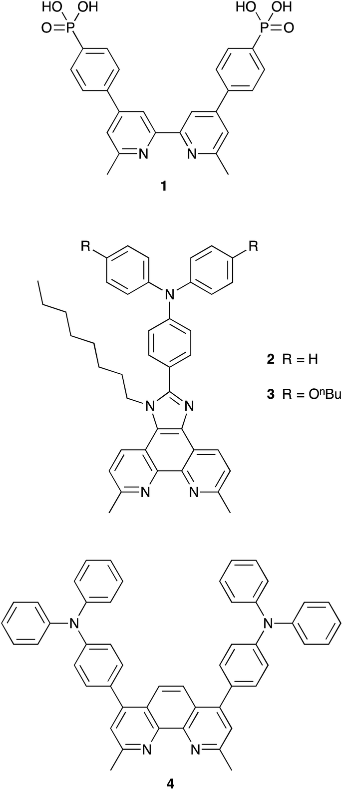 | ||
| Scheme 1 Structures of anchoring ligand 1 and ancillary ligands 2–4. | ||
The I3−/I− electrolyte comprised LiI (0.1 M), I2 (0.05 M), 1-methylbenzimidazole (0.5 M), 1-butyl-3-methylimidazolinium iodide (0.6 M) in 3-methoxypropionitrile. [Co(bpy)3][PF6]2 and [Co(phen)3][PF6]2 were prepared from CoCl2·6H2O as described in the literature.39 [Co(bpy)3][PF6]3 and [Co(phen)3][PF6]3 were prepared by oxidation of the corresponding cobalt(II) complex using [NO][BF4] followed by anion exchange with [NH4][PF6]; the 1H NMR spectra matched literature data.40 See Table 1 for electrolyte compositions.
| Component | Electrolyte E1 | Electrolyte E2 | Electrolyte E3 | Electrolyte E4 |
|---|---|---|---|---|
| Co2+ | [Co(bpy)3][PF6]2 (0.2 M) | [Co(phen)3][PF6]2 (0.2 M) | [Co(bpy)3][PF6]2 (0.2 M) | [Co(phen)3][PF6]2 (0.175 M) |
| Co3+ | [Co(bpy)3][PF6]3 (0.05 M) | [Co(phen)3][PF6]3 (0.05 M) | [Co(bpy)3][PF6]3 (0.05 M) | [Co(phen)3][PF6]3 (0.044 M) |
| LiClO4 | 0.1 M | 0.1 M | 0.1 M | 0.088 M |
| TBP | 0.2 M | 0.2 M | 0.2 M | 0.175 M |
| Solvent | MeCN | MeCN | MPN | MPN |
DSC measurements
J–V measurements were performed using a SolarSim 150 (Solaronix) or LOT Quantum Design LS0811 sun simulator, which was calibrated with a Si-reference cell to 1000 W m−2 prior to the measurements. All cells were completely masked.23,24 Voltage decay was measured on a ModuLab XM electrochemical system.Electrochemical impedance spectroscopy (EIS) measurements were carried out on a ModuLab® XM PhotoEchem photoelectrochemical measurement system setup from Solartron Analytical. The impedance was measured at steady state close to the open-circuit potential of the cell at different light intensities (LED, 590 nm) in the frequency range 0.05 Hz to 400 kHz using an amplitude of 10 mV. The impedance data was fitted to an equivalent circuit model and analysed using ZView® software from Scribner Associates Inc.
Results and discussion
Choice of sensitizers
The heteroleptic copper(I) dyes chosen for the present study are three of a series of sensitizers that we have previously studied in combination with I3−/I− electrolyte in DSCs.38 All contain the phosphonic acid anchoring ligand 1 (Scheme 1); for copper(I) dyes, we have found phosphonic acids to be superior over analogous carboxylic acid anchors.41 Phosphonic acid anchors are also used in ruthenium-based dyes,42 and the strong surface binding is advantageous with respect to carboxylic acid anchors. However, we note that in terms of the rate of electron injection, carboxylic acid anchors may be favoured over phosphonic acids.43 The ancillary ligands 2–4 (Scheme 1) contain a phen metal-binding unit and one or two triphenylamino-domains to enhance light-absorption. Ligands 2 and 3 feature a long alkyl chain to militate against dye-molecule aggregation by intermolecular π-stacking.44 Ligand 3 contains n-butoxy chains on the triphenylamino-unit which are known to improve the performance of DSCs employing triphenylamine-containing organic sensitizers in combination with cobalt electrolytes.31 Due to the steric hindrance of the n-butoxy chains, electron recombination with the electrolyte, which previously was reported to be one of the main issues with this kind of mediator,39 is significantly reduced. All ligands contain methyl substituents adjacent to the N,N′-coordination site to stabilize the copper(I) dyes (tetrahedral, Scheme 2) against irreversible oxidation to copper(II) (square planar).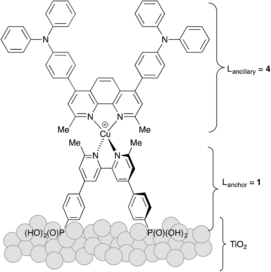 | ||
| Scheme 2 Surface-adsorbed dye [Cu(1)(4)]+ as an example of the three sensitizers investigated. | ||
The copper(I) dyes were assembled in situ on FTO/TiO2 electrodes using a ‘surfaces-as-ligands’ approach which we have established as being effective for complexes which are labile in solution.21 Screen-printed mesoporous TiO2 electrodes with scattering layer were post-treated with aqueous TiCl4 solution using conditions that we have previously optimized.35 Each electrode was immersed in a solution of the phosphonic acid anchoring ligand 1 followed by soaking in a dye-bath containing either [Cu(2)2][PF6], [Cu(3)2][PF6] or [Cu(4)2][PF6]. Ligand exchange leads to the formation of the surface-anchored dyes [Cu(1)(2)]+ (eqn (1)), [Cu(1)(3)]+ or [Cu(1)(4)]+. By eye, the orange colour of the electrodes was consistent with the presence of adsorbed dye, and this was quantified by solid-state absorption spectroscopy using electrodes assembled as described in the Experimental section but without the scattering layer. The observed absorption maxima (λmax ∼ 470 nm) were consistent with those already reported.38
| FTO/TiO2/1 + [Cu(2)2]+ → FTO/TiO2/[(1)Cu(2)]+ + 2 | (1) |
Co2+/Co3+ electrolytes in acetonitrile
The compositions of the Co2+/Co3+ electrolytes are given in Table 1. Initially, we used MeCN as the solvent and the compositions of electrolytes E1 and E2 are typical of Co2+/Co3+ electrolytes employing bpy or phen ligands. The first sensitizer to be investigated was [Cu(1)(3)]+. The open-circuit voltage (VOC), short-circuit current density (JSC), fill factor (ff) and photoconversion efficiency (η) were measured immediately after sealing the DSCs; cells were masked, and reproducibility of the data was checked by using duplicate cells (Table 2). Table 2 also gives performance characteristics of a reference DSC containing the standard ruthenium dye N719 combined with an I3−/I− electrolyte. The right-hand column in Table 2 gives a relative η, setting the value for an N719 reference DSC to 100%. We routinely use two sun simulators (LOT Quantum Design LS0811 and SolarSim 150 instruments) and, as previously discussed,45 DSC characteristics for the same cell recorded on the same day on these instruments (both under irradiation of 1 sun) lead to similar values of VOC but different values of JSC. By using relative η values, we can justifiably compare data measured on different instruments.45| Dye | Electrolyte | Cell number | J SC/mA cm−2 | V OC/mV | ff/% | η/% | Relativebη/% |
|---|---|---|---|---|---|---|---|
| a Measurements were made on a LOT Quantum Design LS0811 sun simulator. b Relative η is relative to N719 set at 100%. | |||||||
| [Cu(1)(3)]+ | E1 (bpy) | 1 | 5.30 | 640 | 69 | 2.32 | 38.1 |
| [Cu(1)(3)]+ | E1 (bpy) | 2 | 5.45 | 652 | 58 | 2.06 | 33.8 |
| [Cu(1)(3)]+ | E2 (phen) | 1 | 5.91 | 735 | 63 | 2.74 | 45.0 |
| [Cu(1)(3)]+ | E2 (phen) | 2 | 5.88 | 731 | 60 | 2.59 | 42.5 |
| N719b | I3−/I− | 13.8 | 705 | 63 | 6.09 | 100 | |
Table 2 shows that there is an increase in both JSC and VOC on changing from [Co(bpy)3]2+/3+ to [Co(phen)3]2+/3+ (from electrolyte E1 to E2). The relative efficiencies of 33.8 and 38.1% for the [Co(bpy)3]2+/3+-containing DSCs, and 42.5 and 45.0% for the [Co(phen)3]2+/3+-containing DSCs are appreciably higher than the 22.5 and 25.7% observed for [Cu(1)(3)]+ combined with a standard I3−/I− electrolyte (Table S1†).38 Although the data were extremely promising, we experienced difficulties with the use of MeCN as solvent. Firstly, the DSCs tended to be unstable, performing poorly after several days. When the dye [Cu(1)(4)]+ was combined with electrolyte E1, orange crystals rapidly formed in the sealed DSC (Fig. 1). Rapid crystal growth was a persistent problem in DSCs containing a combination of [Cu(1)(4)]+ and [Co(bpy)3]2+/3+. Attempts to analyse the crystals by mass spectrometry and X-ray crystallography did not provide definitive identification of the crystalline material. Crystals were also observed in DSCs containing [Cu(1)(4)]+ and [Co(phen)3]2+/3+, although their growth was slower than in electrolyte E1; a substantial fall in JSC was observed after two or more days. The formation of crystals of (MBI)6(HMBI+)2(I−)(I3−) (MBI = N-methylbenzimidazole) from electrolyte components in DSCs has previously been reported,46 but of course, this salt cannot be responsible for the crystals observed in the cobalt-based electrolytes. Other than this latter report, precipitation or crystal formation from liquid electrolytes in DSCs does not appear to have been discussed in detail in the literature.47
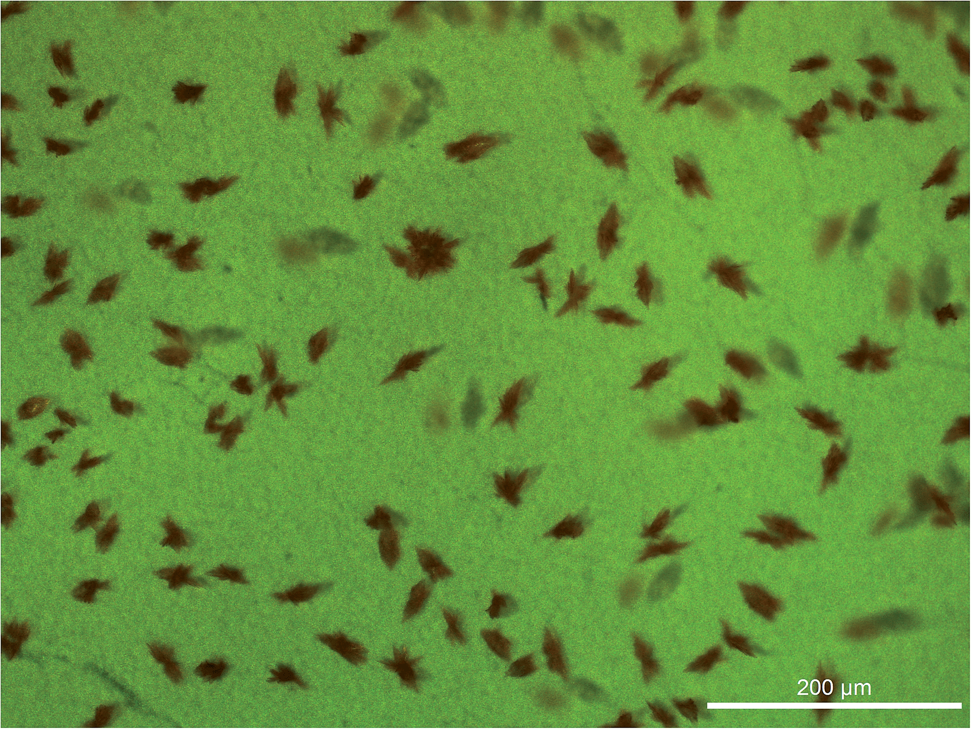 | ||
| Fig. 1 Crystal formation in sealed DSCs containing electrolyte E1 and the dye [Cu(1)(4)]+ (Leica MC170 HD microscope). | ||
Co2+/Co3+ electrolytes in 3-methoxypropionitrile
The problems encountered with the combination of [Cu(1)(4)]+ and electrolytes E1 or E2 led us to change the solvent to 3-methoxypropionitrile (MPN) which is widely employed in DSCs.6,47 Electrolyte E3 differs from E1 only in the solvent variation (Table 1). However, the lower solubility of [Co(phen)3][PF6]3 in MPN compared to MeCN resulted in the use of a 0.044 M solution of [Co(phen)3][PF6]3 in electrolyte E4 rather than the preferred 0.05 M. The concentrations of the other electrolyte components were reduced to maintain the same molar ratios in E3 and E4 (Table 1). Table 3 gives the performance parameters of masked, duplicate cells for each dye/electrolyte combination, and the corresponding J–V curves for the better performing DSC from each pair are depicted in Fig. 2.| Dye | Electrolyte | Cell number | J SC/mA cm−2 | V OC/mV | ff/% | η/% | Relativebη/% |
|---|---|---|---|---|---|---|---|
| a Measurements were made on a SolarSim 150 sun simulator. b Relative η is relative to N719 set at 100%. | |||||||
| [Cu(1)(2)]+ | E3 (bpy) | 1 | 6.98 | 596 | 66 | 2.75 | 38.6 |
| [Cu(1)(2)]+ | E3 | 2 | 6.41 | 605 | 62 | 2.41 | 33.8 |
| [Cu(1)(3)]+ | E3 | 1 | 8.24 | 583 | 61 | 2.92 | 41.0 |
| [Cu(1)(3)]+ | E3 | 2 | 8.66 | 619 | 65 | 3.50 | 49.2 |
| [Cu(1)(4)]+ | E3 | 1 | 9.06 | 598 | 64 | 3.47 | 48.7 |
| [Cu(1)(4)]+ | E3 | 2 | 9.58 | 594 | 65 | 3.69 | 51.8 |
| [Cu(1)(2)]+ | E4 (phen) | 1 | 7.68 | 559 | 64 | 2.73 | 38.3 |
| [Cu(1)(2)]+ | E4 | 2 | 7.15 | 530 | 64 | 2.42 | 34.0 |
| [Cu(1)(3)]+ | E4 | 1 | 8.61 | 637 | 61 | 3.34 | 46.9 |
| [Cu(1)(3)]+ | E4 | 2 | 8.14 | 643 | 56 | 2.92 | 41.0 |
| [Cu(1)(4)]+ | E4 | 1 | 8.54 | 620 | 60 | 3.17 | 44.5 |
| [Cu(1)(4)]+ | E4 | 2 | 8.57 | 622 | 60 | 3.17 | 44.5 |
| N719b | I3−/I− | 17.13 | 650 | 64 | 7.12 | 100 | |
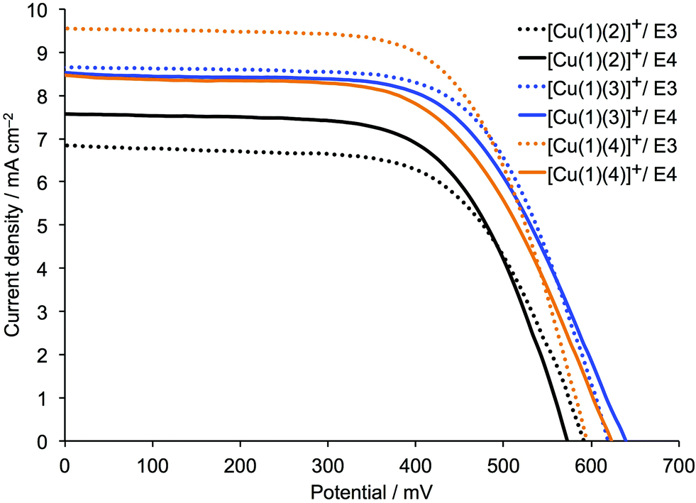 | ||
| Fig. 2 J–V curves measured on the day of sealing DSCs containing the dyes [Cu(1)(2)]+, [Cu(1)(3)]+ or [Cu(1)(4)]+ and electrolytes E3 or E4 (see Table 1). | ||
Irrespective of the cobalt complex used in the electrolyte, DSCs containing sensitizers [Cu(1)(3)]+ or [Cu(1)(4)]+ exhibit higher values of JSC and VOC than those containing [Cu(1)(2)]+. The superior performance of [Cu(1)(4)]+ is consistent with the results obtained using an I3−/I− electrolyte38 (Table S1†). Most importantly, the observed values of JSC for DSCs with cobalt electrolytes are substantially higher than for the same dyes with an I3−/I− electrolyte; values of JSC = 9.58 and 9.06 mA cm−2 for [Cu(1)(4)]+ with electrolyte E3 (Table 3) compare with a range of 5.98–6.81 mA cm−2 for [Cu(1)(4)]+ with I3−/I− (Tables S1 and S2†). For the dyes [Cu(1)(3)]+ and [Cu(1)(4)]+, higher values of VOC are observed for electrolyte E4 than for E3, consistent with the more positive redox potential of the [Co(phen)3]2+/3+ couple versus [Co(bpy)3]2+/3+.29,32 On the other hand, higher values of JSC are obtained for both [Cu(1)(3)]+ and [Cu(1)(4)]+ when the redox mediator is [Co(bpy)3]2+/3+. In terms of DSC efficiencies (Table 3), the use of [Co(bpy)3]2+/3+ is superior to [Co(phen)3]2+/3+.
Fig. 3 shows the EQE spectra of DSCs containing the dyes combined with the [Co(bpy)3]2+/3+ redox shuttle. The first point to note is the differences in the shapes of the EQE spectra compared to the corresponding spectra for the same dyes in combination with I3−/I− electrolyte (Fig. S1†). The gain in EQE in the region between 370 and 420 nm reflects the competing light absorption34,48 of I3− which reduces the number of photons being harvested by the copper dyes. Values of EQEmax show a marked increase on going from an I3−/I− to [Co(bpy)3]2+/3+ redox mediator (Table 4). A comparison of Fig. 3 and S1† also reveals enhanced quantum efficiency at higher wavelengths (570–620 nm) for all three dyes.
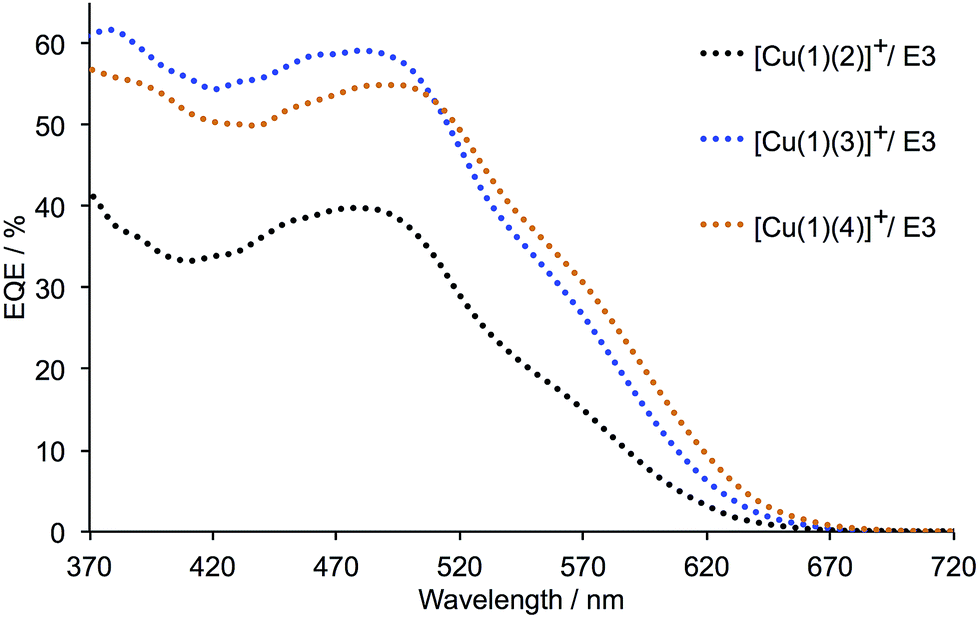 | ||
| Fig. 3 EQE spectra of DSCs containing the dyes [Cu(1)(2)]+, [Cu(1)(3)]+ or [Cu(1)(4)]+ and electrolyte E3 (with [Co(bpy)3]2+/3+). The spectrum for the better performing DSC of each pair measured for each dye is shown; see also Table 3. | ||
| Dye | Electrolyte | EQEmax/% | λ/nm | |
|---|---|---|---|---|
| [Cu(1)(2)]+ | E3 | 39.8 (sh. 17.4) | 480 (sh. 560) | This work |
| [Cu(1)(2)]+ | E3 | 37.0 (sh. 15.7) | 480 (sh. 560) | This work |
| [Cu(1)(2)]+ | I3−/I− | 37.9 | 480 | Ref. 38 |
| [Cu(1)(2)]+ | I3−/I− | 35.3 | 480 | Ref. 38 |
| [Cu(1)(3)]+ | E3 | 59.1 (sh. 30.4) | 480 (sh. 550) | This work |
| [Cu(1)(3)]+ | E3 | 56.1 (sh. 30.0) | 480 (sh. 550) | This work |
| [Cu(1)(3)]+ | I3−/I− | 37.3 | 480 | Ref. 38 |
| [Cu(1)(3)]+ | I3−/I− | 34.7 | 480 | Ref. 38 |
| [Cu(1)(4)]+ | E3 | 54.9 (sh. 30.6) | 490 (sh. 570) | This work |
| [Cu(1)(4)]+ | E3 | 51.3 (sh. 29.3) | 490 (sh. 570) | This work |
| [Cu(1)(4)]+ | I3−/I− | 36.6 (sh. 19.5) | 490 (sh. 570) | Ref. 38 |
| [Cu(1)(4)]+ | I3−/I− | 37.1 (sh. 19.5) | 490 (sh. 570) | Ref. 38 |
The mass transport problem that is known to affect [Co(diimine)3]n+/(n−1)+ redox mediators47 can be investigated by measuring the dependence of JSC for a given DSC on the incident light intensity.34 The DSC parameters for duplicate cells containing [Cu(1)(3)]+ or [Cu(1)(4)]+ and electrolyte E4 measured under different light intensities are given in Table 5. In keeping with the use of the I3−/I− electrolyte in the N719 reference DSC, there is an approximately linear dependence of JSC on light intensity and the photoconversion efficiency is essentially constant. However, the mass transport problem associated with [Co(phen)3]2+/3+ (electrolyte E4) manifests itself in the non-linear dependence between JSC and light intensity seen in Table 5 for each DSC containing the dyes [Cu(1)(3)]+ or [Cu(1)(4)]+.
| Dye | Cell number | Light intensityb/% | J SC/mA cm−2 | V OC/mV | ff/% | η/% |
|---|---|---|---|---|---|---|
| a Measurements were made on a LOT Quantum Design LS0811. b 100% light intensity = 1 sun = 1000 W m−2. | ||||||
| [Cu(1)(3)]+ | 1 | 100 | 4.32 | 632 | 65 | 1.79 |
| [Cu(1)(3)]+ | 1 | 50 | 2.93 | 598 | 68 | 2.39 |
| [Cu(1)(3)]+ | 1 | 10 | 0.75 | 543 | 72 | 2.95 |
| [Cu(1)(3)]+ | 2 | 100 | 4.26 | 634 | 64 | 1.73 |
| [Cu(1)(3)]+ | 2 | 50 | 2.85 | 605 | 69 | 2.37 |
| [Cu(1)(3)]+ | 2 | 10 | 0.65 | 544 | 73 | 2.59 |
| [Cu(1)(4)]+ | 1 | 100 | 4.07 | 609 | 61 | 1.52 |
| [Cu(1)(4)]+ | 1 | 50 | 2.92 | 587 | 65 | 2.23 |
| [Cu(1)(4)]+ | 1 | 10 | 0.79 | 540 | 72 | 3.05 |
| [Cu(1)(4)]+ | 2 | 100 | 4.05 | 620 | 57 | 1.43 |
| [Cu(1)(4)]+ | 2 | 50 | 3.04 | 600 | 61 | 2.24 |
| [Cu(1)(4)]+ | 2 | 10 | 0.81 | 552 | 72 | 3.21 |
| N719 | 1 | 100 | 11.77 | 690 | 72 | 5.89 |
| N719 | 1 | 50 | 5.82 | 664 | 74 | 5.71 |
| N719 | 1 | 10 | 1.32 | 597 | 73 | 5.74 |
Overall, we observe a marked improvement in the photoconversion efficiencies of all three sensitizers in DSCs on going from an I3−/I− to a [Co(bpy)3]2+/3+ or [Co(phen)3]2+/3+ electrolyte using MPN as solvent. The most promising combination of an FTO/TiO2/[Cu(1)(4)]+ photoanode in conjunction with a [Co(bpy)3]2+/3+ redox mediator where efficiencies of 3.47 and 3.69% were achieved; relative to the N719 reference DSC, these values correspond to relative η values of 48.7 and 51.8%. Significantly, the values of η = 3.47 and 3.69% are the highest efficiencies achieved for a heteroleptic copper(I) sensitizer using the ‘surfaces-as-ligands’ approach, the previous record being 3.16% with respect to 7.63% for N719.25
Electrochemical impedance spectroscopy (EIS)
EIS was used to evaluate the electrochemical behaviour of the DSCs in more detail. This technique allows one to measure the internal impedances of the DSC, and key parameters including the recombination resistance (Rrec), chemical capacitance (Cμ) and the electron lifetime (τ) (which is the product of Rrec and Cμ), can be obtained.49,50 Three sets of duplicate DSCs were used in the investigation. All DSCs contained the sensitizer [Cu(1)(4)]+ which was shown in the studies described above to be the best performing of [Cu(1)(2)]+, [Cu(1)(3)]+ and [Cu(1)(4)]+. Each set of DSCs used a different redox mediator ([Co(bpy)3]2+/3+, [Co(phen)3]2+/3+ or I3−/I−). The electrolyte compositions for the cobalt-based electrolytes are given in Table 1. The DSCs in the EIS study correspond to those in Table 3 with electrolytes E3 and E4, and to the DSCs from a set made using [Cu(1)(4)]+ and a standard I3−/I− electrolyte (Table S2†) which showed 2.43 and 2.46% efficiencies. The performances of these I3−/I−-containing DSCs are consistent with previously published data.38 Measured EIS data at two different light intensities are presented in Tables 6 and 7. Table 6 shows the impedance spectra of the DSCs, with one cell of each configuration measured at a bias light intensity of 22 mW cm−2. At this light intensity, the transport resistance (Rt) of the electrons in the semiconducting TiO2 is negligible. Furthermore, at this light intensity, the VOC values follow the same trend as those found in the J–V measurements under 1 sun (see Tables 3 and S2†), where electrolyte E4 gives the highest VOC values for [Cu(1)(4)]+. Table 7 shows the parameters obtained at low light intensity, where the transport resistance, Rt, can be studied. Ld which is the length of electron diffusion “backwards” in the semi-conductor should, in a well performing DSC electrode, be at least as long as the thickness of the porous TiO2 layer L to minimize back reactions.50 Hence, Ld/L > 1 must be fulfilled, since this implies that transit time in the semi-conductor is shorter than the electron lifetime. Pleasingly, in all DSCs measured in this study (Table 7), Ld (which is calculated as the square root of Rrec/Rt) is larger than L, and significantly so for the I3−/I− electrolyte cells, due to their higher Rrec and lower transport resistance.| Electrolyte used with dye [Cu(1)(4)]+ | R d/Ω | R rec/Ω | C μ/μF | R Pt/Ω | C Pt/μF | τ/ms | V OC/mV | η /% |
|---|---|---|---|---|---|---|---|---|
| a The cell efficiency is that of the particular cell measured with EIS. | ||||||||
| E3 (bpy) cell 1 | 112 | 86 | 479.3 | 7 | 4.5 | 41 | 646 | 3.47 |
| E3 (bpy) cell 2 | 97 | 72 | 507.8 | 7 | 4.3 | 36 | 641 | 3.69 |
| E4 (phen) cell 1 | 171 | 107 | 646.1 | 15 | 5.5 | 69 | 661 | 3.17 |
| E4 (phen) cell 2 | 157 | 103 | 641.2 | 31 | 2.3 | 66 | 665 | 3.17 |
| I3−/I− cell 1 | 5 | 224 | 461.8 | 8 | 5.6 | 103 | 579 | 2.73 |
| I3−/I− cell 2 | 6 | 188 | 486.8 | 10 | 5.2 | 91 | 593 | 2.62 |
| Electrolyte used with dye [Cu(1)(4)]+ | R t/Ω | R rec/Ω | C μ/μF | R Pt/Ω | C Pt/μF | τ/ms | L d/L (dimensionless) | V OC/mV |
|---|---|---|---|---|---|---|---|---|
| E3 (bpy) cell 1 | 93 | 2360 | 125.6 | 5 | 8.5 | 296 | 5 | 515 |
| E3 (bpy) cell 2 | 47 | 2079 | 141.0 | 6 | 4.9 | 293 | 7 | 515 |
| E4 (phen) cell 1 | 87 | 2753 | 162.3 | 15 | 6.3 | 447 | 6 | 518 |
| E4 (phen) cell 2 | 61 | 2325 | 180.3 | 29 | 2.3 | 419 | 6 | 540 |
| I3−/I− cell 1 | 40 | 6817 | 172.4 | 8 | 5.5 | 1175 | 13 | 462 |
| I3−/I− cell 2 | 35 | 5478 | 200.3 | 11 | 4.9 | 1097 | 12 | 474 |
From Table 6, Fig. 4 and 5c, it can be seen that the diffusion resistance, Rd (which is represented as the third arc from the left in each spectrum in Fig. 4a for DSCs with cobalt-electrolytes) is considerably pronounced. This particular arc is, however, barely seen in the spectrum for the DSC containing the I3−/I− based redox mediator. The relatively bulky cobalt complexes restrict the mass transport and lower the diffusion coefficient compared to the iodide system.34,51 Furthermore, it is clearly seen that Rd is larger for the [Co(phen)]2+/3+ than for the [Co(bpy)3]2+/3+.
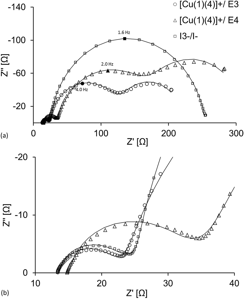 | ||
| Fig. 4 (a) Nyquist plot from EIS measurements of three DSCs having the electrolyte systems E3, E4 and I3−/I−, and (b) a zoom-in of the high frequency region. The larger Rrec of the I3−/I−-based system as well as the pronounced Rd of the cobalt-based electrolytes are clearly seen. The graphs presented here are the ones from each of the duplicate cells denoted ‘cell 1’. | ||
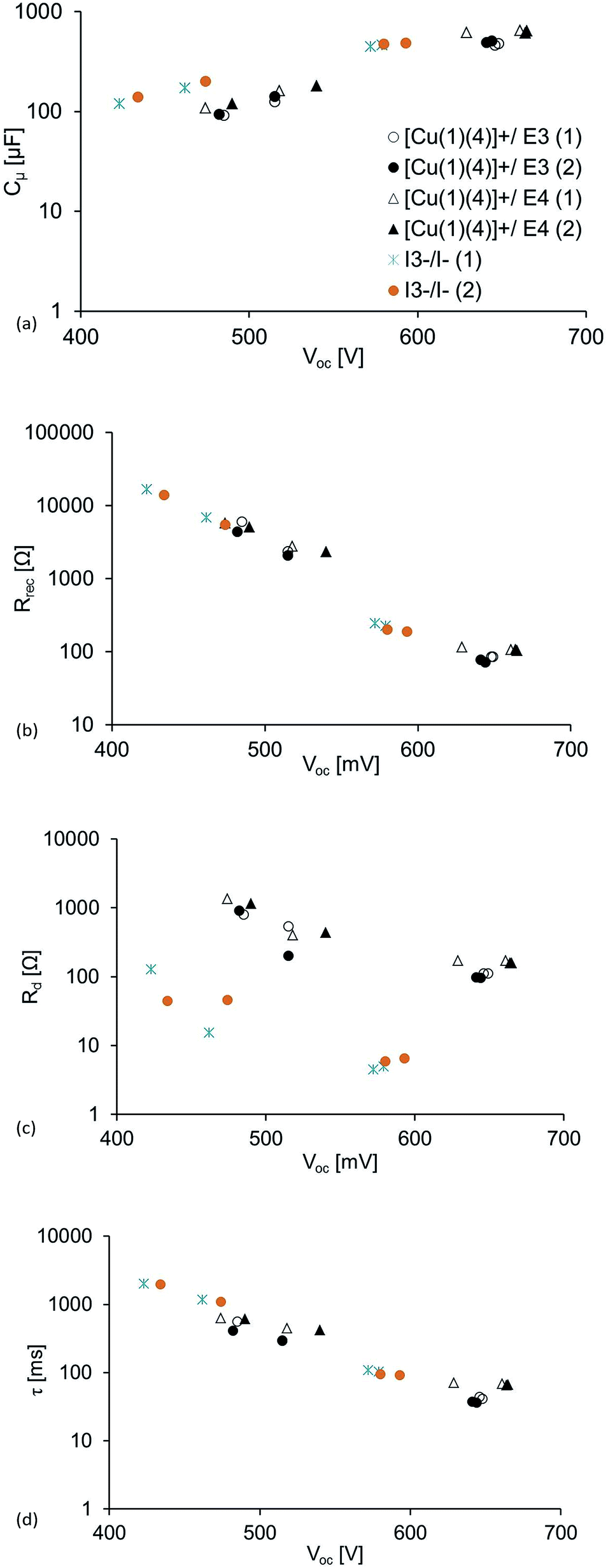 | ||
| Fig. 5 Plots of the parameters at different light intensities (0.22, 0.44, 13.2 and 22.0 mW cm−2) against VOC: (a) chemical capacitance, (b) recombination resistance, (c) diffusion resistance and (d) electron lifetime. For light intensities of 0.44 and 22 mW cm−2, values of VOC are given in Tables 6 and 7. Each VOC value is a result of each given light intensity. | ||
The recombination resistance, Rrec, is generally lower for the DSCs having cobalt electrolytes compared to I3−/I− (Table 6, Fig. 5b). This is also seen in the Nyquist plot in Fig. 4a, as the magnitude of Rrec (which is represented by the second arc from the left in each spectrum) is significantly larger for the DSC having the I3−/I− electrolyte. This is in agreement with the fast electron transfer from I− to regenerate the dye compared to the lower rate of reduction of I3− which minimizes the back reaction interfacial process (higher Rrec).52 For the cobalt-based electrolytes, the consequence is that the faster back reaction kinetics of the cobalt mediators decrease Rrec in accordance with the discussion above. However, the simpler outer sphere electron transfer of the cobalt redox mediators (in contrast to the iodide species, which involve the creation and breaking of chemical bonds as opposed to simple electron transfer),40 give the cobalt DSCs their higher JSC and chemical capacitance, Cμ. Cμ is related to the total density of electrons in the semi-conductor and typically rises exponentially at higher light intensities;49 this is also seen in Fig. 5a. Rt, which is strongly dependent on the electrolyte,49 is higher in the cobalt-based DSCs than in the I3−/I−-containing DSCs (Table 7). As the voltage of the cell is higher and Rt becomes insignificant, the more positive redox potential of the cobalt mediators and simpler charge transfer kinetics result in a higher Cμ. The relatively high Rrec of the I3−/I−-based DSCs results in the larger values of electron lifetime presented in Fig. 5b and Tables 6 and 7; this decreases exponentially upon increasing the light intensity. However, the high Cμ of the cobalt-based DSCs results in the larger JSC seen for these DSCs (Table 3).
If one considers VOC, Rrec and Cμ for DSCs with [Co(bpy)3]2+/3+ and [Co(phen)3]2+/3+, it appears that the [Co(phen)3]2+/3+ electrolyte should be superior of the two in terms of DSC efficiency. However, its higher resistance to mass transport is detrimental, limiting the JSC to a greater extent, and resulting in the [Co(bpy)3]2+/3+ electrolyte having the highest DSC efficiency. On the other hand, in the iodide systems, Rd is insignificant, but here, the much lower VOC and, despite the high Rrec, the moderate chemical capacitance result in the more modest overall DSC performance.
Conclusions
The performances of DSCs containing the sensitizers [Cu(1)(2)]+, [Cu(1)(3)]+ and [Cu(1)(4)]+ combined with each of the redox shuttles [Co(bpy)3]3+/2+ [Co(phen)3]3+/2+ or I3−/I− have been investigated. For all three dyes, the photoconversion efficiency is enhanced by using [Co(bpy)3]2+/3+ or [Co(phen)3]2+/3+ in place of I3−/I−. This is consistent with the faster charge-transfer kinetics and more positive redox potential of [Co(bpy)3]2+/3+ or [Co(phen)3]2+/3+versus I3−/I−. The best performing DSC contains the [Cu(1)(4)]+ dye combined with a [Co(bpy)3]2+/3+ redox mediator; value of η = 3.47 and 3.69% for duplicate DSCs relative to η = 7.12% for an N719 reference DSC are the highest efficiencies achieved for a heteroleptic copper(I) sensitizer using our ‘surfaces-as-ligands’ approach. The results of an EIS study demonstrate that the improved performance of the [Co(bpy)3]2+/3+ or [Co(phen)3]2+/3+-containing DSCs compared to the devices containing the I3−/I− electrolyte is mainly due to the more rapid charge exchange kinetics exhibited by the cobalt redox mediators and their more positive redox potentials. This results in an improved chemical capacitance and VOC. However, on going from I3−/I− to cobalt-based cells, the recombination rate increases as a consequence of the faster kinetics. In the present investigation which uses 3-methoxypropionitrile as solvent, [Cu(1)(4)]+ combined with the [Co(bpy)3]2+/3+ electrolyte leads to the highest DSC efficiency. However, given the EIS parameters and the high VOC for the [Co(phen)3]2+/3+ system, it seems likely that a solvent with a lower viscosity should render the [Co(phen)3]2+/3+ electrolyte the more advantageous, and we are currently investigating this option.Acknowledgements
We thank the Swiss National Science Foundation, the European Research Council (Advanced Grant 267816 LiLo), the Swiss Nano Institute (for the purchase of the EIS instrument) and the University of Basel for financial support.Notes and references
- M. Grätzel, Acc. Chem. Res., 2009, 42, 1788 CrossRef PubMed; M. Grätzel, Inorg. Chem., 2005, 44, 6841 CrossRef PubMed; M. Grätzel, J. Photochem. Photobiol., C, 2003, 4, 145 CrossRef and references therein.
- Dye Sensitized Solar Cells, ed. K. Kalyanasundaram, CRC Press, Boca Raton, 2010 Search PubMed.
- A. Mishra, M. Fischer and P. Bäuerle, Angew. Chem., Int. Ed., 2009, 48, 2474 CrossRef CAS PubMed.
- A. Yella, H.-W. Lee, H. N. Tsao, C. Yi, A. K. Chandiran, M. K. Nazeeruddin, E. W.-G. Diau, C.-Y. Yeh, S. M. Zakeeruddin and M. Grätzel, Science, 2011, 334, 629 CrossRef CAS PubMed.
- T. Higashino and H. Imahori, Dalton Trans., 2015, 44, 448 RSC.
- A. Hagfeldt, G. Boschloo, L. Sun, L. Kloo and H. Pettersson, Chem. Rev., 2010, 110, 6595 CrossRef CAS PubMed.
- A. Hagfeldt and M. Grätzel, Acc. Chem. Res., 2000, 33, 269 CrossRef CAS PubMed.
- Y. Xie, Y. Tang, W. Wu, Y. Wang, J. Liu, X. Li, H. Tian and W.-H. Zhu, J. Am. Chem. Soc., 2015, 137, 14055 CrossRef CAS PubMed.
- H. Ozawa, Y. Okuyama and H. Arakawa, ChemPhysChem, 2014, 15, 1201 CrossRef CAS PubMed.
- K. Kakiage, Y. Aoyama, T. Yano, T. Otsuka, T. Kyomen, M. Unno and M. Hanaya, Chem. Commun., 2014, 50, 6379 RSC.
- C.-Y. Chen, M. Wang, J.-Y. Li, N. Pootrakulchote, L. Alibabaei, C.-H. Ngoc-le, J.-D. Decoppet, J.-H. Tsai, C. Grätzel, C.-G. Wu, S. M. Zakeeruddin and M. Grätzel, ACS Nano, 2009, 3, 3103 CrossRef CAS PubMed.
- S. Mathew, A. Yella, P. Gao, R. Humphry-Baker, B. F. E. Curchod, N. Ashari-Astani, I. Tavernelli, U. Rothlisberger, M. K. Nazeeruddin and M. Grätzel, Nat. Chem., 2014, 6, 242 CrossRef CAS PubMed.
- K. Kakiage, Y. Aoyama, T. Yano, K. Oya, T. Kyomen and M. Hanaya, Chem. Commun., 2015, 51, 6315 RSC.
- Z. Yao, M. Zhang, H. Wu, L. Yang, R. Li and P. Wang, J. Am. Chem. Soc., 2015, 137, 3799 CrossRef CAS PubMed.
- K. Kakiage, Y. Aoyama, T. Yano, K. Oya, J.-I. Fujisawa and M. Hanaya, Chem. Commun., 2015, 51, 15894 RSC.
- N. Alonso-Vante, J.-F. Nierengarten and J.-P. Sauvage, J. Chem. Soc., Dalton Trans., 1994, 1649 RSC.
- N. Armaroli, G. Accorsi, F. Cardinali and A. Listorti, Top. Curr. Chem., 2007, 280, 69 CrossRef CAS and references therein.
- A. Lavie-Cambot, M. Cantuel, Y. Leydet, G. Jonusauskas, D. M. Bassani and N. D. McClenaghan, Coord. Chem. Rev., 2008, 252, 2572 CrossRef CAS.
- S. Sakaki, T. Kuroki and T. Hamada, J. Chem. Soc., Dalton Trans., 2002, 840 RSC.
- T. Bessho, E. C. Constable, M. Graetzel, A. Hernandez Redondo, C. E. Housecroft, W. Kylberg, M. K. Nazeeruddin, M. Neuburger and S. Schaffner, Chem. Commun., 2008, 3717 RSC.
- C. E. Housecroft and E. C. Constable, Chem. Soc. Rev., 2015, 44, 8386 RSC and references therein.
- M. Magni, P. Biagini, A. Colombo, C. Dragonetti, D. Roberto and A. Valore, Coord. Chem. Rev., 2016, 322, 69 CrossRef CAS.
- H. J. Snaith, Energy Environ. Sci., 2012, 5, 6513 Search PubMed.
- H. J. Snaith, Nat. Photonics, 2012, 6, 337 CrossRef CAS.
- F. J. Malzner, S. Y. Brauchli, E. C. Constable, C. E. Housecroft and M. Neuburger, RSC Adv., 2014, 4, 48712 RSC.
- M. Sandroni, L. Favereau, A. Planchat, H. Akdas-Kilig, N. Szuwarski, Y. Pellegrin, E. Blart, H. Le Bozec, M. Boujtita and F. Odobel, J. Mater. Chem. A, 2014, 2, 9944 CAS.
- Z. Yu, M. Gorlov, J. Nissfolk, G. Boschloo and L. Kloo, J. Phys. Chem. C, 2010, 114, 10612 CAS.
- G. Boschloo and A. Hagfeldt, Acc. Chem. Res., 2009, 42, 1819 CrossRef CAS PubMed.
- Z. Sun, M. Liang and J. Chen, Acc. Chem. Res., 2015, 48, 1541 CrossRef CAS PubMed.
- B. Pashaei, H. Shahroosvand and P. Abbasi, RSC Adv., 2015, 5, 94814 RSC.
- S. M. Feldt, E. A. Gibson, E. Gabrielsson, L. Sun, G. Boschloo and A. Hagfeldt, J. Am. Chem. Soc., 2010, 132, 16714 CrossRef CAS PubMed.
- T. W. Hamann, Dalton Trans., 2012, 41, 3111 RSC.
- See for example: S. Nakade, Y. Makimoto, W. Kubo, T. Kitamura, Y. Wada and S. Yanagida, J. Phys. Chem. B, 2005, 109, 3488 CrossRef CAS PubMed; S. Yun, Y. Liu, T. Zhang and S. Ahmad, Nanoscale, 2015, 7, 11877 RSC.
- H. Nusbaumer, S. M. Zakeeruddin, J.-E. Moser and M. Grätzel, Chem.–Eur. J., 2003, 9, 3756 CrossRef CAS PubMed.
- B. Bozic-Weber, E. C. Constable, S. O. Fürer, C. E. Housecroft, L. J. Troxler and J. A. Zampese, Chem. Commun., 2013, 49, 7222 RSC.
- L. N. Ashbrook and C. M. Elliott, J. Phys. Chem. C, 2013, 117, 3853 CAS.
- B. Bozic-Weber, S. Y. Brauchli, E. C. Constable, S. O. Fürer, C. E. Housecroft, F. J. Malzner, I. A. Wright and J. A. Zampese, Dalton Trans., 2013, 42, 12293 RSC.
- S. O. Fürer, B. Bozic-Weber, M. Neuburger, E. C. Constable and C. E. Housecroft, RSC Adv., 2015, 5, 69430 RSC.
- See for example: B. M. Klahr and T. W. Hamann, J. Phys. Chem. C, 2009, 113, 14040 CAS.
- See for example: S. Carli, E. Busatto, S. Caramori, R. Boaretto, R. Argazzi, C. J. Tipson and C. A. Bignozzi, J. Phys. Chem. C, 2013, 117, 5142 CAS.
- B. Bozic-Weber, E. C. Constable, C. E. Housecroft, P. Kopecky, M. Neuburger and J. A. Zampese, Dalton Trans., 2011, 40, 12584 RSC.
- H. Zabri, I. Gillaizeau, C. A. Bignozzi, S. Caramori, M.-F. Charlot, J. Cano-Boquera and F. Odobel, Inorg. Chem., 2003, 42, 665 CrossRef PubMed and references cited therein.
- See for example: M. Nilsing, P. Persson and L. Ojamäe, Chem. Phys. Lett., 2005, 415, 375 CrossRef CAS.
- Y. Ooyama and Y. Harima, Eur. J. Org. Chem., 2009, 2903 CrossRef CAS.
- F. J. Malzner, S. Y. Brauchli, E. Schönhofer, E. C. Constable and C. E. Housecroft, Polyhedron, 2014, 82, 116 CrossRef CAS.
- A. Fischer, H. Pettersson, A. Hagfeldt, G. Boschloo, L. Kloo and M. Gorlov, Sol. Energy Mater. Sol. Cells, 2007, 91, 1062 CrossRef CAS.
- J. Wu, Z. Lan, J. Lin, M. Huang, Y. Huang, L. Fan and G. Luo, Chem. Rev., 2015, 115, 2136 CrossRef CAS PubMed.
- S. M. Feldt, G. Wang, G. Boschloo and A. Hagfeldt, J. Phys. Chem. C, 2011, 115, 21500 CAS.
- F. Fabregat-Santiago, J. Bisquert, G. Garcia-Belmonte, G. Boschloo and A. Hagfeldt, Sol. Energy Mater. Sol. Cells, 2005, 87, 117 CrossRef CAS.
- J. Bisquert, F. Fabregat-Santiago, I. Mora-Sero, G. Garcia-Belmonte and S. Gimenez, J. Phys. Chem. C, 2009, 113, 17278 CAS.
- H. Nusbaumer, J.-E. Moser, S. M. Zakeeruddin, M. K. Nazeeruddin and M. Graetzel, J. Phys. Chem. B, 2001, 105, 10461 CrossRef CAS.
- A. Colombo, C. Dragonetti, M. Magni, D. Roberto, F. Demartin, S. Caramori and C. A. Bignozzi, ACS Appl. Mater. Interfaces, 2014, 6, 13945 CAS.
Footnote |
| † Electronic supplementary information (ESI) available: Tables S1 and S2: DSC parameters for DSCs with [Cu(1)(2)]+, [Cu(1)(3)]+ and [Cu(1)(4)]+ and I3−/I− electrolyte; Table S3: EIS data; Fig. S1: EQE spectra for DSCs with [Cu(1)(2)]+, [Cu(1)(3)]+ and [Cu(1)(4)]+ and I3−/I− electrolyte. See DOI: 10.1039/c6ta04879j |
| This journal is © The Royal Society of Chemistry 2016 |