 Open Access Article
Creative Commons Attribution 3.0 Unported Licence
The use of protic ionic liquids with cathodes for sodium-ion batteries
T.
Vogl†
a,
C.
Vaalma†
a,
D.
Buchholz
a,
M.
Secchiaroli
b,
R.
Marassi
b,
S.
Passerini
*a and
A.
Balducci
*a
aHelmholtz Institute Ulm (HIU), Electrochemistry I, 89081 Ulm, Germany. E-mail: stefano.passerini@kit.edu; andrea.balducci@kit.edu
bSchool of Science and Technology, University of Camerino, I-62032 Camerino, Italy
First published on 6th June 2016
Abstract
Herein, we report for the first time the use of a protic ionic liquid as a component of a new Na-ion battery electrolyte. The protic ionic liquid has been tested in combination with two different types of sodium-ion cathode materials, polyanionic Na3V2(PO4)3 and layered Na0.67Mn0.89Mg0.11O2, in order to reveal its impact on the electrode material electrochemical performance. The results evidence that this novel electrolyte performs very well in combination with a polyanionic electrode material, while it shows poor performance with a layered oxide material.
Introduction
Induced by the growing concern about ending fossil fuel reserves and increasing awareness of environmental pollution, batteries are attracting enormous interest since they allow the storage of electrochemical energy with little maintenance and relatively high power and energy capability for mobile as well as stationary applications. Within this storage technology, lithium-ion batteries (LIBs) are the most widely used representatives, which have benefited from intensive research efforts over the last 30 years. Triggered by the search for cost reduction and growing concerns about the price and availability of Li-ion raw material resources, a significant part of battery research has changed its focus to sodium-ion batteries (SIBs), which share the working principle with LIBs but benefit from more abundant and less pricy raw materials, backed by a foreseen comparable performance.1For both battery technologies, similar electrolytes are used, which are based on organic solvents like propylene, ethylene and dimethyl carbonate and alkali-metal conductive salts with hexafluorophosphate as the anion.2 Although these relatively cheap solutions have enabled the boom of rechargeable Li-ion batteries in the past few years, a major drawback has ever since dominated the discussions and concerns about these batteries: organic electrolyte-based batteries embody safety issues due to the flammability of the solvents. As a result of unwanted events, such as alkali metal dendritic plating upon charging at low temperature resulting in short circuit between the anode and cathode, spontaneous heat release can lead to degradation of the anodic SEI, which in turn generates further heat finally ending in the so-called thermal runaway, causing a massive volume expansion, burning or even explosion of the cell.3 Although eminent efforts have been made to reduce this risk, external heat, unfortunate coincidences and aging still represent a potential risk. A possible solution could therefore be an electrolyte, which shows a different, lower and negligible ability to catch fire, at best with similar chemical–physical properties so that it could easily replace the presently used solutions and therefore act as a drop-in technology with little expense for exchange. The most suitable candidates for this are the so-called ionic liquids (ILs), salts which are liquid at ambient temperature and show low vapor pressure, ionic character and high thermal and chemical stabilities.4
IL-based electrolytes are generally free of additional solvents and only consist of weakly coordinating ionic pairs, with organic molecular cations and inorganic anions.2,5 Unlike for LIBs, relatively few studies have been reported for the use of IL-based electrolytes in SIBs.2,6–8 General drawbacks of ILs in LIBs and SIBs are associated with their high viscosity, which results in low ionic mobility and, finally, cell performance especially at high current densities.2,4 Therefore, one strategy to overcome this issue has been the structural modification of the common organic cations replacing a side chain with a proton, i.e., forming a protic ionic liquid (PIL). Electrolytes based on PILs were successfully used in combination with materials for LIBs.4,9,10 Interestingly, to the best of our knowledge, there is no study available for the application of PIL-based electrolytes in SIBs. This is surprising, since protic ionic liquids have shown comparably higher current density capabilities in LIB studies, i.e., using lithium salts.4,9,10
Consequently, the aim of this work is to verify if PILs are also suitable for implementation in SIBs. For this purpose, sodium bis(trifluoromethanesulfonyl)imide (NaTFSI) was introduced into N-butyl-pyrrolidinium bis(trifluoromethanesulfonyl)imide (PyrH4TFSI) to form a sodium-ion conducting electrolyte further characterized for conductivity, viscosity, electrochemical stability, and cycling stability. As cathode materials, sodium vanadium phosphate (Na3V2(PO4)3, NVP) and sodium manganese magnesium oxide (Na0.67Mn0.89Mg0.11O2, NaMM) were used while the anode consisted of activated carbon (AC). For comparison, electrolytes based on an aprotic ionic liquid (AIL, N-butyl-N-methyl-pyrrolidinium bis(trifluoromethanesulfonyl)imide, Pyr14TFSI) and an organic solvent (propylene carbonate, PC) were prepared and characterized in the same way.
Experimental
The pyrrolidinium-based PIL (PyrH4TFSI) was synthesized following a procedure analogous to that described elsewhere.11 PC (BASF, 99.95%) and Pyr14TFSI (Iolitec, 99%) were used without further purification. The water contents of the ILs and PC were measured using coulometric Karl-Fischer titration, and were found to be lower than 10 ppm. As electrolytes, solutions of 0.3 M NaTFSI (Solvionic, 99.5%) in the above mentioned “solvents” were prepared dissolving the NaTFSI at 60 °C. Conductivity and viscosity were determined as reported in a previous study.12 All the electrochemical tests were carried out with three-electrode Swagelok® type cells. The cells were assembled in an argon-filled glovebox with oxygen and water contents lower than 1 ppm. Electrochemical stability windows (ESWs) were determined by linear sweep voltammetry (LSV) as reported in the literature.13 All measurements were carried out using a silver wire as the pseudo-reference electrode.Sodium vanadium phosphate (NVP) composite electrodes were prepared as in a previously published study.14 The composition of the dry electrodes was 80 wt% of the active material, 10 wt% of conductive agent Super C65® and 10 wt% of polyvinylidene fluoride (PVdF) as the binder. The average electrode mass loading was 1.6 mg cm−2; the electrode area was 1.13 cm2.
Oversized activated carbon (AC)-based anodes were prepared by stirring polytetrafluoroethylene (PTFE, 60 wt% aqueous dispersion, Sigma Aldrich), Super C65® as a conductive agent and the activated carbon DLC Super 30® (NORIT®), dry weight ratio: 5 wt% of PTFE, 10 wt% of Super C65® and 85 wt% of DLC Super 30®, in ethanol at 150 °C until the latter was mostly evaporated. The resulting slurry was then casted on a glass plate and electrodes with a diameter of 12 mm were cut out and then dried.
Na0.67Mn0.89Mg0.11O2 (NaMM) was synthesized by a simplified co-precipitation method: an aqueous solution of magnesium and manganese acetates (tetrahydrates, ≥99.0%, Sigma Aldrich) was added dropwise to a stirring aqueous solution of 0.67 equivalents of sodium carbonate (monohydrate, ≥99.5%, Sigma Aldrich) in ambient atmosphere. Due to the insufficient amount of carbonate in the combined mixture, the precipitation of manganese and magnesium carbonate is incomplete and an excess of dissolved magnesium and manganese acetates remains dissolved. The combined solutions are stirred for 30 minutes, followed by the removal of water in a rotary evaporator until a viscous residue remains. The residue is heated up in a muffle furnace in air for 4 hours at 375 °C (heating rate 1.5 °C min−1) and furnace cooled. The resulting dark powder is ground, annealed at 900 °C for 6 hours (heating rate 5 °C min−1), furnace cooled, ground, screened over a sieve (mesh size below 45 μm) and used for electrode preparation without any further treatment.
NaMM electrodes were prepared by ball milling 85 wt% active material, 10 wt% Super C65 (IMERYS), and 5 wt% PVdF (6020 Solef®, Arkema Group) with consequent casting on Al foil. The active material mass loading of the electrodes was about 2.1 mg cm−2.
NVP-based electrodes were used as working electrodes and oversized AC electrodes were used as counter and reference electrodes. As a separator, a Whatman® GF/D glass microfiber filter (675 μm thickness) drenched with 200 μL of electrolyte was used. All the electrochemical measurements were carried out using a MACCOR Series 4000 battery tester. Constant current cycling (CC) was carried out at 40 °C using current densities ranging from 1C to 20C taking into account the theoretical capacity of NVP (118 mA h g−1) when cycled between 2.5 and 3.8 V (vs. Na/Na+).14 The cells were cycled via the limited cathode with cut-off potentials of 0.1 and 1.1 V (vs. AC). The voltage of the full cells and anodes was also recorded. Galvanostatic cycling experiments with NaMM were carried out in the same way with cut-off potentials of −0.7 and 1.3 V using a constant current density of 100 mA g−1.
Ex situ X-ray diffraction investigations were performed using Cu Kα radiation (λ = 0.154 nm) on a Bruker D8 Advance diffractometer in the 2θ range from 10° to 90°. For that, cycled electrodes were disassembled from the cells in an argon filled dry box, rinsed with DMC, fixed on a single crystal silicon sample holder with carbon tape and sealed with a plastic dome before transfer to the XRD. Samples for ex situ SEM were handled in the same way and SEM images were recorded using a high-resolution scanning electron microscope (FE-SEM, Zeiss Auriga).
Results and discussion
Transport properties
Fig. 1a compares the ionic conductivity of the three electrolytes (0.3 M NaTFSI in PyrH4TFSI, Pyr14TFSI and PC) in the temperature range between 20 and 80 °C. This concentration of conductive salt was chosen, since it was the maximum amount of salt soluble in PyrH4TFSI. At temperatures up to 50 °C, the PC-based electrolyte has the highest conductivity (e.g. 5.3 mS cm−1 at 40 °C). However, the ionic conductivity of the IL-based electrolytes increases faster than that of the organic solvent-based one. Accordingly, the ionic conductivities of 0.3 M NaTFSI electrolyte solutions increase after heating (20 to 80 °C) from 3.6 to 8.8, 1.5 to 12.5 and 1.3 to 10.7 mS cm−1 for PC, PyrH4TFSI and Pyr14TFSI solvents, respectively.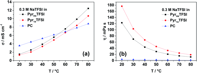 | ||
| Fig. 1 Ionic conductivity (a) and viscosity (b) of the investigated electrolytes (0.3 M NaTFSI in PyrH4TFSI; Pyr14TFSI or PC) in the temperature range between 20 and 80 °C. | ||
It is important to notice that the PIL-based electrolyte is slightly more conductive than the AIL-based one. This trend has already been shown for IL-based electrolytes containing LiTFSI.9 At 40 °C, 0.3 M NaTFSI in PyrH4TFSI has a conductivity of 3.9 mS cm−1, while in Pyr14TFSI, the conductivity is 3.4 mS cm−1.
Not only does the ionic conductivity of an electrolyte matter for the application in electrochemical energy storage devices, but its viscosity is also important for the cell performance because of appropriate electrode wetting. The viscosity of the considered electrolytes is shown in Fig. 1b. The trend for the two IL-based electrolytes is again the same as that observed for lithium-based electrolytes with the respective PIL and AIL.9 The viscosity of 0.3 M NaTFSI in PyrH4TFSI on average is about 30% lower than 0.3 M NaTFSI in Pyr14TFSI. However, the PC-based electrolyte is the lowest over the whole considered temperature range between 20 and 80 °C. At 40 °C, the viscosity of the organic electrolyte is 2.7 mPa s, while the PIL- and AIL-based ones have viscosities of 43.7 and 67.1 mPa s, respectively.
Electrochemical characterization
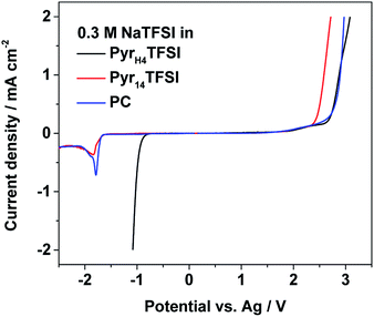
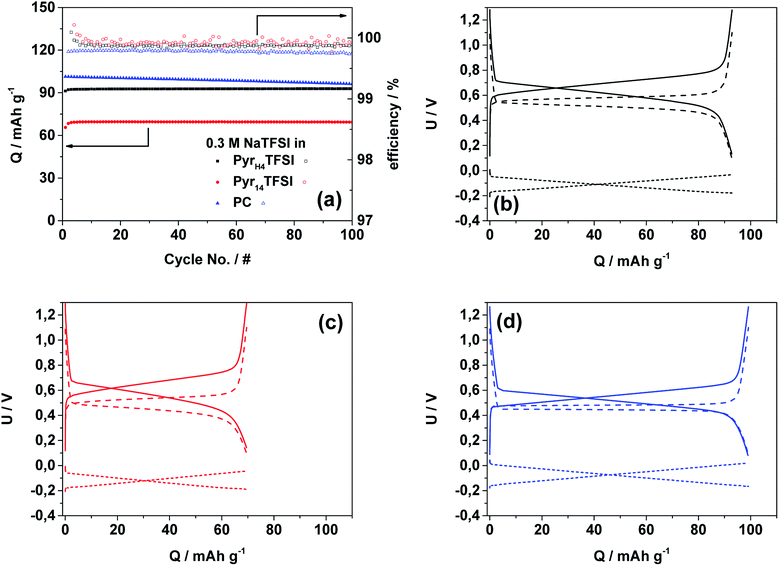
Fig. 2 reports the electrochemical stability windows of all investigated electrolytes at 40 °C. Their anodic stability is at least 2.0 V (vs. Ag pseudo-reference), i.e., in accordance with results of other TFSI-based systems.15,16 In principle, all three electrolytes should share the same anodic stability limit determined by the decomposition of TFSI, but due to the use of the pseudo-reference electrode, these results can be only taken as an indication for stability limits rather than exact values.15,16 The cathodic stability of the PIL-based electrolyte matches with the stability reported for this PIL.17 However, the cathodic stability of the AIL- and PC-based electrolyte is unexpected, since both solvents should be stable until sodium plating. Using the Ag pseudo-reference electrode, in fact, sodium plating should occur at a potential of ∼−2.7 V (vs. Ag) whereas in these measurements, it occurs already at ∼−1.7 V (vs. Ag). The reason for this discrepancy should be further investigated. Nevertheless, taking into account the obtained results, the electrochemical stability limits appear large enough for the cycling of NVP–AC or NaMM–AC full cells.The cycling stability and the corresponding efficiency of the NVP–AC cells cycled in the three different electrolytes are displayed in Fig. 3a. The current density corresponds to 1C (118 mA g−1). The cell made with the PIL-based electrolyte shows a very stable cycling behavior for 100 cycles with a specific discharge capacity of ∼93 mA h g−1 and coulombic efficiency of >99.9%. The cell with the AIL-based electrolyte shows, as well, very stable cycling behavior and similar coulombic efficiency, but about 25% lower specific discharge capacity (∼69 mA h g−1). It should be noted that the obtained coulombic efficiency values are extremely high, demonstrating that the use of activated carbon as the anode effectively eliminates the effect of unwanted compounds usually forming at the reactive sodium metal/electrolyte interface.3 The cell cycled with the organic electrolyte shows the highest initial discharge capacity (∼101 mA h g−1), but coupled with substantial fading. The capacity loss during these 100 cycles is ∼5 mA h g−1 and, even more important, the coulombic efficiency is slightly lower (>99.8%).
Fig. 3b–d display the 50th cycle voltage profiles of the NVP–AC cells. For all electrolytes, the typical shape of the NVP charge/discharge profiles is visible.14 However, it should be highlighted that the voltage efficiency (calculated from the average voltages during charge and discharge processes) is different for the three cells. The cell containing the PC-based electrolyte reveals the highest voltage efficiency of about 94%, while those of the cells containing the ILs are about 90%.
The performance at increased current densities is depicted in Fig. 4. At a first glance, the PC-based electrolyte outperforms both IL-based electrolytes. In fact, the capacity retention of the cells containing the IL-based electrolytes is significantly lower than that of the cell including the organic electrolyte. At 10C rate, the latter cell still delivers 88% of its initial capacity while those using the PIL- and AIL-based electrolytes deliver only 24% and 17%, respectively. It is important to notice that the specific capacity of the PyrH4TFSI-based electrolyte is always higher than that of the Pyr14TFSI-based one, indicating that, also in SIBs, the use of PILs appears beneficial compared to that of AILs. In a previous study, we showed that the performance of a similar lithium-based material (lithium vanadium phosphate, LVP) in PIL-based electrolytes almost reached the same performance as that in organic solvent-based electrolytes.9 However, considering the above reported result, this does not seems to be the case in SIBs. Nevertheless, it should be remarked that the lithium salt concentration in the mentioned study was higher (0.5 M LiTFSI) compared to the sodium salt concentration used in this study (0.3 M NaTFSI). The lower salt concentration in the considered PIL-based electrolyte leads to lower viscosities but, very likely, it has a negative influence on the Na+ ion mobility, which in turn leads to lower electrochemical performance at increased current densities. In spite of this, the results showed above clearly prove that sodium-based materials can be successfully cycled in PILs. In addition, these results show that the use of PILs can enable an improved electrochemical performance with respect to specific capacity and capacity retention as compared to conventional AIL-based electrolytes.
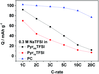 | ||
| Fig. 4 Rate performance of NVP‖AC cells at 40 °C at different current densities (1C is equivalent to 118 mA g−1) with 0.3 M NaTFSI in PyrH4TFSI; Pyr14TFSI or PC as the electrolyte. | ||
Cycling of NaMM
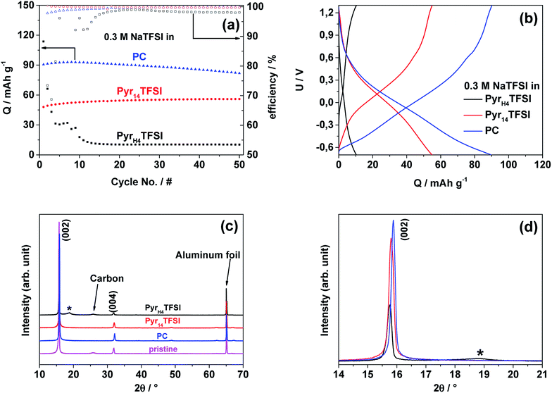
To identify the feasibility of layered cathode materials with PILs, NaMM was electrochemically tested in the same setup as NVP for comparison (Fig. 5a). Layered materials have been reported to work well with both organic carbonate- and AIL-based electrolytes.18–21 In fact, NaMM electrodes show good and stable electrochemical performance with a capacity of about 90 mA h g−1 and 57 mA h g−1 in the PC- and AIL-based electrolyte, respectively. Unfortunately, a rapid capacity fade in the PIL-based electrolyte is observed. The different electrochemical performance is in good accordance with the potential profiles of the 25th cycle in Fig. 5b, in which a strong polarization of the PIL-based cell is observed. The voltage efficiencies underline these different reversibilities. The cell containing the PIL-based electrolyte reveals the lowest voltage efficiency of about 36% while the cells containing the AIL- and PC-based electrolytes show voltage efficiencies of 89% and 87% respectively. These results seem to suggest that a different interaction between the NaMM electrode and the three investigated electrolytes is taking place. It is known that layered materials are more sensitive to proton intercalation with respect to polyanionic materials, like NVP, leading to rapid structural degradation and fading of electrochemical performance.22–26 Taking this point into account, it is reasonable to suppose that the proton in the PIL cation might be responsible for the capacity fade observed above. Previously, PIL-based electrolytes have been proved to be compatible with a large variety of anodic and cathodic materials for LIBs.9,17,27,28To the best of our knowledge, this work represents the first attempt toward the use of a PIL-based electrolyte in combination with a layered cathode such as NaMM. In order to reveal the origin of the above-mentioned degradation process, we have performed ex situ XRD of NaMM electrodes, cycled in PIL- and PC-based electrolytes. The X-ray diffractograms in the 2θ range of 10–70° and 14–21° are depicted in Fig. 5c and d, respectively. It should be noted that all diffractograms were normalized on the intensity and position of the main aluminum foil reflection (65.25° 2θ). The comparison of the X-ray diffractograms of the pristine material and cycled electrodes indicates a strong preferred orientation in the latter. For the cycled electrodes, the (002) diffraction peak shows a lower intensity and is broadened for the cell cycled in the PIL-based electrolyte, which indicates a change in the direction of the c-axis. The most significant difference, however, is a broad reflection at about 19° 2θ (marked with an asterisk) which is only found in the diffractogram of the electrode cycled in the PIL-based electrolyte. The position of the new reflection is in good accordance with the reported protonated layered structures and offers a reasonable explanation for the rapidly fading electrochemical performance.29 Note that phase transitions to O-type phases as well as water intercalation can be excluded as the origin for the diffraction peak since all cells were disassembled when the electrode potential was below 3.4 V (vs. Na/Na+) and avoiding exposure to humid air (i.e., handled in an argon atmosphere).30 The sensitivity of layered oxides towards Na+–H+ exchange is most probably related to the higher reactivity of the oxygen anions in layered oxides than that in polyanionic materials (e.g. phosphates like NVP).23 The driving force for the Na+–H+ exchange could be the increased positive charge density of the proton as compared to Na+ as well as the formation of hydrogen bridge bonds.31 The intercalation of protons seems to be irreversible, reasonably reducing (or even blocking) the Na-ion diffusion pathways in the cathode structure, leading to increased electrode polarization.25 The SEM images in Fig. 6 indicate the formation of a surface layer in the PIL-based electrolyte which is in accordance with the formation of a protonated layered phase in the XRD measurements. Considering these results, the use of PIL-based electrolytes in combination with Na-based layered oxides appears therefore problematic. It has to be noticed that the formation of the protonated phase in Na-based layered oxides is more likely than in the Li-based one due to the difference in the cation size, interlayer distance, and charge density as well as repulsion of adjacent layers.23,25,29 For this reason, the behavior of Li-based layered oxides in PIL-based electrolytes could be different. Nevertheless, further investigations appear necessary to confirm the abovementioned hypothesis. These investigations, however, are out of the scope of this study and are not further considered herein.
 | ||
| Fig. 6 SEM images of cycled NaMM-based electrodes (from left to right: pristine vs. cycled in PIL vs. cycled in PC). | ||
Conclusions
In this study, we showed for the first time that a PIL-based electrolyte can be used with a polyanionic SIB cathode material, NVP, showing improved electrochemical performance in comparison with AILs. As a matter of fact, the NVP–AC cell using the PIL-based electrolyte offers higher specific capacity with respect to the “classical” AIL. Furthermore, the use of this novel electrolyte allows the realization of devices with high cycling stability. Taking these results into account, PILs can be therefore seen as a new and promising class of electrolytes for SIBs. Nevertheless, further investigations are certainly needed. First of all, it will be necessary to investigate the Na+ transference number in these electrolytes and to compare it with those of “conventional ILs” and organic electrolytes. Furthermore, it will be necessary to optimize the cell configuration/electrode balance. This, in fact, would further increase the cell performance and it would allow a more precise evaluation of the energy density which could be delivered by these types of devices.32 Finally, another important aspect that should be investigated in the future is the behavior of layered oxide-based cathodes in this class of electrolytes. From the results reported here, such an electrode/electrolyte combination seems to be somehow problematic and therefore, such studies will be important to assess the advantages and limitations related to the use of PIL-based electrolytes in SIBs.Acknowledgements
The authors wish to thank the Deutsche Forschungsgemeinschaft (DFG) within the project “Protic ionic liquids as electrolytes for lithium-ion batteries” for the financial support.References
- N. Yabuuchi, K. Kubota, M. Dahbi and S. Komaba, Chem. Rev., 2014, 114, 11636–11682 CrossRef CAS PubMed.
- A. Ponrouch, D. Monti, A. Boschin, B. Steen, P. Johansson and M. R. Palacín, J. Mater. Chem. A, 2015, 3, 22–42 RSC.
- G. G. Eshetu, S. Grugeon, H. Kim, S. Jeong, L. Wu, G. Gachot, S. Laruelle, M. Armand and S. Passerini, ChemSusChem, 2016, 9, 462–471 CrossRef CAS PubMed.
- D. R. MacFarlane, N. Tachikawa, M. Forsyth, J. M. Pringle, P. C. Howlett, G. D. Elliott, J. H. Davis, M. Watanabe, P. Simon and C. A. Angell, Energy Environ. Sci., 2014, 7, 232–250 Search PubMed.
- C. Austen Angell, Y. Ansari and Z. Zhao, Faraday Discuss., 2012, 154, 9–27 RSC.
- J. Serra Moreno, G. Maresca, S. Panero, B. Scrosati and G. B. Appetecchi, Electrochem. Commun., 2014, 43, 1–4 CrossRef CAS.
- A. Ponrouch, R. Dedryvère, D. Monti, A. E. Demet, J. M. Ateba Mba, L. Croguennec, C. Masquelier, P. Johansson and M. R. Palacín, Energy Environ. Sci., 2013, 6, 2361 Search PubMed.
- A. Fukunaga, T. Nohira, R. Hagiwara, K. Numata, E. Itani, S. Sakai and K. Nitta, J. Appl. Electrochem., 2016, 46, 487–496 CrossRef CAS.
- T. Vogl, S. Menne, R.-S. Kühnel and A. Balducci, J. Mater. Chem. A, 2014, 2, 8258 RSC.
- T. Vogl, S. Menne and A. Balducci, Phys. Chem. Chem. Phys., 2014, 16, 25014–25023 RSC.
- L. Timperman, P. Skowron, A. Boisset, H. Galiano, D. Lemordant, E. Frackowiak, F. Béguin and M. Anouti, Phys. Chem. Chem. Phys., 2012, 14, 8199 RSC.
- R.-S. Kühnel and A. Balducci, J. Phys. Chem. C, 2014, 118, 5742–5748 CrossRef.
- S. Menne, R.-S. Kühnel and A. Balducci, Electrochim. Acta, 2013, 90, 641–648 CrossRef CAS.
- A. Moretti, M. Secchiaroli, D. Buchholz, G. Giuli, R. Marassi and S. Passerini, J. Electrochem. Soc., 2015, 162, A2723–A2728 CrossRef CAS.
- G. B. Appetecchi, M. Montanino, D. Zane, M. Carewska, F. Alessandrini and S. Passerini, Electrochim. Acta, 2009, 54, 1325–1332 CrossRef CAS.
- G. B. Appetecchi, M. Montanino, A. Balducci, S. F. Lux, M. Winterb and S. Passerini, J. Power Sources, 2009, 192, 599–605 CrossRef CAS.
- S. Menne, M. Schroeder, T. Vogl and A. Balducci, J. Power Sources, 2014, 266, 208–212 CrossRef CAS.
- L. G. Chagas, D. Buchholz, L. Wu, B. Vortmann and S. Passerini, J. Power Sources, 2014, 247, 377–383 CrossRef CAS.
- I. Hasa, S. Passerini and J. Hassoun, J. Power Sources, 2016, 303, 203–207 CrossRef CAS.
- D. Buchholz, C. Vaalma, L. Gomes and S. Passerini, J. Power Sources, 2015, 282, 581–585 CrossRef CAS.
- D. Buchholz, L. G. Chagas, M. Winter and S. Passerini, Electrochim. Acta, 2013, 110, 208–213 CrossRef CAS.
- J. Choi and A. Manthiram, J. Mater. Chem., 2006, 16, 1726–1733 RSC.
- R. Benedek, M. M. Thackeray and A. van de Walle, Chem. Mater., 2008, 20, 5485–5490 CrossRef CAS.
- Y. Wang, J. Lou, W. Wu, C. Wang and Y.-Y. Xia, J. Electrochem. Soc., 2007, 154, A228 CrossRef CAS.
- X. Gu, J. Liu, J. Yang, H. Xiang, X. Gong and Y. Xia, J. Phys. Chem. C, 2011, 115, 12672–12676 CrossRef CAS.
- C. M. Fang and G. a. de Wijs, Chem. Mater., 2006, 18, 1169–1173 CrossRef CAS.
- A. Brandt, J. Pires, M. Anouti and A. Balducci, Electrochim. Acta, 2013, 108, 226–231 CrossRef CAS.
- N. Bockenfeld, M. Willeke, J. Pires, M. Anouti and A. Balducci, J. Electrochem. Soc., 2013, 160, A559–A563 CrossRef.
- W. C. Hamilton and J. A. Ibers, Acta Crystallogr., 1963, 16, 1209–1212 CrossRef CAS.
- D. Buchholz, L. G. Chagas, C. Vaalma, L. Wu and S. Passerini, J. Mater. Chem. A, 2014, 2, 13415 RSC.
- Q. Shu, L. Chen, Y. Xia, X. Gong and X. Gu, J. Phys. Chem. C, 2013, 117, 6929–6932 CrossRef CAS.
- F. Wang, X. Wang, Z. Chang, X. Wu, X. Liu, L. Fu, Y. Zhu, Y. Wu and W. Huang, Adv. Mater., 2015, 27, 6962 CrossRef CAS PubMed.
Footnote |
| † TV and CV contributed equally to this work. |
| This journal is © The Royal Society of Chemistry 2016 |

