
 Open Access Article
 This Open Access Article is licensed under a
 Creative Commons Attribution 3.0 Unported Licence
N-doped Li4Ti5O12 nanoflakes derived from 2D protonated titanate for high performing anodes in lithium ion batteries†
Erwin F.
Rodriguez
ab,
Fang
Xia
bc,
Dehong
Chen
*a,
Anthony F.
Hollenkamp
d and
Rachel A.
Caruso
*ab
aParticulate Fluids Processing Centre, School of Chemistry, The University of Melbourne, Melbourne, VIC 3010, Australia. E-mail: rcaruso@unimelb.edu.au; dehongc@unimelb.edu.au
bManufacturing, The Commonwealth Scientific and Industrial Research Organisation (CSIRO), Clayton, VIC 3168, Australia
cSchool of Engineering and Information Technology, Murdoch University, Murdoch, WA 6150, Australia
dEnergy, The Commonwealth Scientific and Industrial Research Organisation (CSIRO), Clayton, VIC 3168, Australia
First published on 29th April 2016
Abstract
Safety, the current rate capability and cycle life are important features of high performance lithium ion batteries (LIBs). Herein dehydrated, mesoporous nitrogen doped Li4Ti5O12 (N-LTO) containing highly crystalline, 2D nano-sized flakes were prepared via a facile hydrothermal process followed by calcination in air. A layered protonated titanate with a small quantity of nitrogen compounds was precipitated by the hydrothermal method, and used as the precursor for Li4Ti5O12 (LTO). The presence of nitrogen within the intermediate led to nitrogen doped LTO after calcination. The optimal calcination temperature was obtained by monitoring the thermal transformation from the protonated titanate precursor to spinel LTO using in situ and ex situ analyses. The optimised N-LTO nanoflakes showed excellent high current rate capability and cycle life when applied as an anode for LIBs: having a capacity of 95.4 ± 16.5 mA h g−1 when cycled at a very high current (120C), and exhibiting a low capacity loss (∼9%) after 2288 cycles at 5C. These properties are attributed to the combined characteristics of these N-LTO nanoflakes, including abundant mesopores, high surface area (86 m2 g−1), 2D nanoflake building blocks, nitrogen doping, as well as being water-free and highly crystalline.
1 Introduction
Despite powering most portable electronic devices, lithium ion batteries (LIBs) do not fulfil the requirements for large-scale applications (e.g. electric vehicles) in terms of safety, lifespan, and power capability.1 The low working potential vs. Li/Li+ of commonly-used carbonaceous anodes leads to the formation of an unstable solid electrolyte interface, and to lithium metal plating at fast charging rates, both of which cause safety issues.1,2 LTO offers a safe working potential of 1.55 V vs. Li/Li+.3,4 Moreover, LTO has “zero-strain” owing to minimal variation in the unit cell during lithiation/delithiation,5,6 which makes a long cycle-life in LIBs possible. However, the intrinsic low electric conductivity of LTO (10−7 to 10−8 S cm−1)6,7 gives rise to a large polarisation at high currents that reduces the current rate capability. Also, LTO has a moderate Li+ diffusion rate that is not sufficient for achieving high current rate capabilities.8Employing porous networks comprising nano-sized building blocks is an effective approach to improve the current rate capability of LIBs that does not require the use of an excessive amount of conductive additives.9 Of particular interest are thin nanoflake morphologies, due to a reduced diffusion pathlength for Li ions, which can enhance the lithiation rate at high currents.10 Moreover, mesoporous networks can provide abundant paths for electron travel and an intimate electrolyte/LTO contact.10,11 Another strategy to enhance the electron transport within LTO is nitrogen doping12–16 with most methods to dope N in LTO conducted at high temperature in the presence of a nitrogen source and under a reducing atmosphere.12,13,15
It is recognised that high crystallinity is required to obtain high performance LTO, thus many syntheses used high temperature to ensure high crystallinity,17–19 but at the cost of excessive crystal growth. Alternatively, a low annealing temperature preserves the morphology and a high surface area, but the product suffered high crystallographic strain, exhibiting poor performance under galvanostatic cycling.18 Furthermore, a low annealing temperature does not ensure the total removal of water of crystallisation from the structure. Trace water can react with phosphorus pentafluoride, PF5, (generated from the decomposition of lithium hexafluorophosphate, LiPF6) to form acidic hydrogen fluoride, which has destructive effects on both battery cell components and active materials.20,21
Porous LTO for LIBs has been fabricated using diverse synthesis strategies,22–30 including spray drying, plasma jet synthesis, templating, hydrothermal synthesis and solution-combustion synthesis. Herein the synthesis of a nitrogen doped mesoporous LTO structure (N-LTO) composed of nanoflakes with an optimal crystallinity and a water-free composition is described. A soluble titanium peroxide solution was hydrothermally treated to achieve a layered lithium protonated titanate (LHT) with nanoflake morphology having NH4+ intercalated between the TiO6 octahedral layers. On calcination, mesoporous N-LTO structures were achieved. The thermal transformation from the orthorhombic LHT to cubic LTO was investigated by in situ and ex situ techniques to find an optimal calcination temperature for preparing an active LTO material with a highly crystalline, water-free composition, high surface area, mesoporosity and 2D nano-sized flakes. Moreover, the nitrogen doping was achieved without the further addition of nitrogen sources. The integrated features of the fabricated N-LTO enable this mesoporous material to deliver an ultra-high rate capability with long cycle-life.
2 Experimental
2.1 Materials and synthesis
The chemicals used during synthesis were titanium(IV) isopropoxide (TIP, 97% Sigma-Aldrich), lithium hydroxide monohydrate (LiOH·H2O, 99.99% Sigma-Aldrich), ammonia solution (NH3·H2O, 30% AR Chem-Supply) and hydrogen peroxide (H2O2, 30% AR Chem-Supply). All chemicals were used as received. The water used in all experiments was passed through a Millipore Milli-Q ultrapure water purification system and had a resistivity higher than 18.2 MΩ cm.The LTO was synthesised as follows: a 0.2 M titanium peroxide solution with lithium was prepared by stirring water (100 mL), LiOH·H2O (1.145 g), NH3 solution (9.55 mL) and H2O2 solution (30.35 mL) together for 10 minutes at room temperature, followed by the dropwise addition of TIP (9.16 mL added within 1 min). The mixture was stirred until all the precipitates had dissolved. Caution should be taken when adding TIP, because the reaction is exothermic. The solution was then made up to 150 mL with water, resulting in a transparent yellow solution with pH ∼ 11. The final mixture had NH3![[thin space (1/6-em)]](https://www.rsc.org/images/entities/char_2009.gif) :H2O2:LiOH:Ti molar ratios of 5:10:0.91:1. An aliquot of this solution (40 mL) was placed into a PTFE-lined autoclave (volume 50 mL) and heated in an oven at 140 °C for 15 h. Once cooled to room temperature, the resultant light yellowish precipitate together with the mother solution (pH ∼ 11) was heated at ∼80 °C with constant stirring for ∼1 h to evaporate the water. The powder was further dried in an oven at ∼90 °C for 1 h. This dried product was labelled LHT. A portion of the dried powder was separated for the thermal transformation study, while the rest was heated in air from room temperature to 550 °C at 2 °C min−1 and then calcined at the targeted temperature for 2 h in order to transform the LHT into N-LTO.
:H2O2:LiOH:Ti molar ratios of 5:10:0.91:1. An aliquot of this solution (40 mL) was placed into a PTFE-lined autoclave (volume 50 mL) and heated in an oven at 140 °C for 15 h. Once cooled to room temperature, the resultant light yellowish precipitate together with the mother solution (pH ∼ 11) was heated at ∼80 °C with constant stirring for ∼1 h to evaporate the water. The powder was further dried in an oven at ∼90 °C for 1 h. This dried product was labelled LHT. A portion of the dried powder was separated for the thermal transformation study, while the rest was heated in air from room temperature to 550 °C at 2 °C min−1 and then calcined at the targeted temperature for 2 h in order to transform the LHT into N-LTO.
2.2 Characterisation
Powder X-ray diffraction (XRD) measurements were conducted on a Bruker D8 Advances Diffractometer with Cu Kα radiation at room temperature, while Rietveld quantitative phase analysis of the XRD data was performed using Topas v4.2 software. Scanning electron microscopy (SEM) and energy dispersive X-ray spectroscopy (EDS) were performed on a FEI Quanta 200F environmental scanning electron microscope to observe the morphology and the chemical composition of the sample. The samples were not sputter-coated. Transmission electron microscopy (TEM), high resolution TEM (HRTEM) images and selected area electron diffraction (SAED) patterns were obtained on a FEI Tecnai F20 transmission electron microscope at 200 kV. Thermogravimetric analysis (TGA) and single differential thermal analysis (DTA) were conducted simultaneously on a Mettler Toledo TGA/SDTA851e instrument. Samples were heated from 25 to 600 °C at 2, 5 or 10 °C min−1 under air (30 mL min−1). Derivative thermogravimetry (DTG) was obtained by taking the derivative of the mass loss percentage (TGA) curve. Nitrogen gas sorption data were collected using a Micromeritics TriStar 3000 surface area and porosity analyser. Before the test, the samples were degassed under vacuum at 120 °C overnight. To determine the specific surface area, a standard multipoint Brunauer–Emmett–Teller method (BET) was applied to the adsorption data in the P/P0 range from 0.05 to 0.20. To obtain the pore diameter distribution, the Barrett–Joyner–Halenda (BJH) model was applied using the adsorption branch of the isotherms. Attenuated total reflectance-Fourier transform infrared (ATR-FTIR) spectra were obtained using a Bruker TENSOR 27 spectrometer equipped with an ATR sampling accessory (GladiATR, PIKE Technologies) at room temperature after drying the samples at 120 °C overnight.The in situ high temperature X-ray diffraction (HTXRD) experiment for monitoring phase transformation was performed on an Inel Equinox 3000 powder diffractometer using Co Kα radiation (λ = 0.1789 nm). The diffractometer is equipped with a Debye–Scherrer CPS120 position-sensitive detector, which spans a 2θ range of 0–120° and hence allows XRD data to be collected rapidly.31 The powder materials were loaded into a fused quartz glass capillary tube (1 mm diameter × 0.05 mm wall thickness × 50 mm in length), which was then fixed to the X-ray beam centre. The capillary was heated to 570 °C by a stream of hot air 3 mm beneath the capillary with a heating rate of 2 °C min−1. The temperature was calibrated using a potassium nitrate temperature standard, which undergoes a phase transition at 128.0 °C and melts at 333.6 °C. During the experiment, the capillary was open to air, and was rotated (30 rpm) continuously to ensure temperature homogeneity and to minimise potential effects of preferred orientation. Each XRD pattern was collected for 2 min, which means each XRD pattern represents a temperature increase of about 4 °C during the heating stage.
The chemical composition of the sample surface was recorded using an X-ray photoelectron spectrometer (XPS) VG ESCALAB 220i-XL (UK) equipped with a twin crystal monochromated Al Kα X-ray source, which emitted a photon energy of 1486.6 eV at 10 kV and 22 mA. A typical operating pressure of ∼7 × 10⁻⁹ mbar was employed. Spectral resolution was fixed at either 1.0 eV (survey scans) or 0.05 eV (regional scans). Curve fitting and quantification of XPS spectra were conducted using CasaXPS software. Ti 2p and N 1s peaks were curve-fitted using a Gaussian/Lorentzian (30) line shape with Shirley background type. Binding energy was calibrated with respect to the C 1s peak at 285.0 eV.
2.3 Electrochemical characterisation
The working electrode was prepared by thoroughly mixing 80 wt% synthesised N-LTO, 10 wt% carbon black (∼40 nm size, Super P®), and 10 wt% polyvinylidene difluoride (PVDF, Sigma-Aldrich) dissolved in N-methyl-2-pyrrolidone (NMP, Aldrich). The slurry was uniformly cast on an etched Al foil (30 μm thickness, JCC Co. Ltd.) and then dried at 80 °C before roll-pressing. The electrodes were further dried overnight under vacuum at 100 °C to remove residual water and NMP. The typical loading of active material was ∼2 mg cm−2 (32 ± 3 μm in thickness). Discs of 15.5 mm diameter were punched out, and half coin cells (CR2032) were assembled in an argon-filled glove box using lithium metal as the counter electrode, porous polyethylene membrane (5P09B, SOLUPOR®, Lyndall) as a separator, and LiPF6 (1 M) dissolved in a mixture of ethylene carbonate, dimethyl carbonate, and diethyl carbonate (EC:DMC:DC = 1:1:1 v/v) as the electrolyte. The galvanostatic charge/discharge test was performed using a MACCOR series 4000 battery tester, increasing the current every 5 cycles between 1 and 3 V with rates of 0.2, 0.5, 1.0, 2.0, 5.0, 10, 20, 40, 60, 80 and 120C (using a theoretical capacity of 175 mA h g−1). In total, 4 half-cells were tested for each sample (the results are presented as means ± standard deviations). The cyclic voltammetry (CV) measurements were carried out by a Solartron 1470 Multistat battery tester unit at various scan rates within 1 and 3 V. The electrochemical impedance spectroscopy (EIS), at a bias potential of 3.1 V, was carried out by applying a sine wave with amplitude of 10 mV over the frequency range from 100 kHz to 0.1 Hz by using a frequency response analyser (Solartron 1255B). A commercial LTO (com-LTO, Titan Kogyo, Ltd.) was used as a control sample.
3 Results and discussion
To fabricate a high performance N-LTO for LIBs, layered LHT was first prepared by hydrothermal crystallisation from a titanium peroxide solution containing Li+ ions, and then N-LTO was produced by calcination of LHT at an optimal temperature.The 2D LHT nanoflakes are shown in the corresponding SEM and TEM images (Fig. 1a and c). These nanoflakes were randomly orientated, which gave porous features to the dried LHT agglomerates. The mesoporosity of LHT was confirmed by the nitrogen gas sorption, revealing a type IV isotherm and a pore diameter distribution centred at around 7.6 nm (Fig. 2a and b, respectively). The LHT nanoflakes were 20–40 nm in width and 3–6 nm in thickness (Fig. 1c and d). The 2D morphology and thinness of these nanoflakes facilitates the formation of 2D LTO nanoflakes after an optimised calcination. Also, the random arrangement of the LHT nanoflakes helps in retaining porous features. A layered orthorhombic structure was revealed by XRD, with Rietveld refinement lattice parameters (a = 16.90, b = 3.78 and c = 2.99 Å) that are in close agreement with layered Li1.81H0.19Ti2O5·xH2O (JCPDS Card No. 47-0123).32 The HRTEM image (Fig. 1d) shows the lattice fringes with an approximate 0.78 nm d-spacing in the lateral view of a nanosheet that can be assigned to the (200) plane of layered orthorhombic LHT. An XPS spectrum was recorded to identify the elemental oxidation states of the dried LHT (Fig. 2). Nitrogen was revealed in the survey and high resolution XPS scans of the LHT (Fig. 2c and e, respectively), revealing an estimated atomic percentage of 2.1%. In the high resolution scan (Fig. 2e), two peaks were found in the N 1s region. The main peak at 407.6 eV can be related to NO3− with an oxidation state of +5 for nitrogen.33 This nitrate is expected to be adsorbed on the surface since intercalation of NO3− between the layers of the orthorhombic LHT would be prohibited as a result of repulsive forces between NO3− and the negative charge of “TiO6” octahedrons. The hump at ∼400 eV (LHT in Fig. 2e) could be assigned to the N 1s binding energy of a small quantity of ammonium cations,34 which might be intercalated between the TiO6 octahedron layers of the LHT. Nitrate formed from NH3 oxidation by H2O2 during the hydrothermal synthesis. It is worth noting that the intercalation of Li+ within the TiO6 layers is more favourable than that of NH4+ and H3O+ due to the low ionic size (ionic size: Li+ = 0.76 Å < H3O+ = 0.90 Å < NH4+ = 1.61 Å)35 and high electropositive features of Li+. The Ti 2p double peak at 458.7 and 464.4 eV (Ti 2p1/2 and 2p3/2, Fig. 2f) is in line with a Ti oxidation state of +4.13,36 Moreover, the EDS spectrum (Fig. S1†) presented peaks mainly for titanium and oxygen, with a trace amount of nitrogen. This small presence of nitrogen is in accordance with the XPS observations.
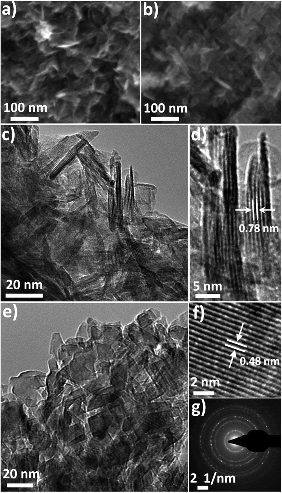 | ||
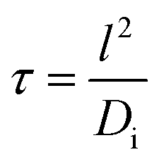
| Fig. 1 (a) SEM and (c and d) TEM images of the LHT showing the 2D morphology. (b) SEM and (e) TEM images of the N-LTO after calcination at 550 °C showing the 2D nanoflake building blocks. (f) HRTEM image showing the lattice fringe spacing of the (111) plane and (g) the corresponding SAED pattern of N-LTO nanoflakes, confirming the Li4Ti5O12 crystal phase. | ||
 | ||
| Fig. 2 (a) Nitrogen sorption isotherms and (b) BJH adsorption pore diameter distribution for uncalcined LHT and N-LTO after calcination at 550 °C, as indicated. (c and d) XPS survey scan for the uncalcined LHT and N-LTO after calcination at 550 °C, respectively. High-resolution (e) N 1s and (f) Ti 2p XPS spectra for the layered LHT and calcined N-LTO, as indicated in the images. | ||
LTO nanoflakes can provide high Li ion mobility due to the nanoscale length for Li ion diffusion. Also, porous structures can facilitate the infiltration of electrolyte, and provide an interconnected network that enhances electron travel. Therefore, to fabricate a material with these characteristics from the LHT, careful control of the thermal phase transformation process from orthorhombic LHT to spinel LTO is required, and the optimal calcination temperature was determined to be when high crystallinity and small crystal growth with minor 2D morphology change was observed. The thermal phase transformation was revealed by combining the results of thermal analysis, in situ HTXRD, ex situ XRD and FTIR spectrometry. Fig. 3a and b show the thermal analysis (TGA and DTG curves) obtained by heating LHT at 2 °C min−1 and the HTXRD patterns recorded at the same heating rate, respectively. Additional thermal analysis data (Fig. S2a and b†) obtained by heating LHT samples at 5 and 10 °C min−1 are provided in the ESI† along with a discussion. The HTXRD suggested that the calcination proceeded via a simple phase transformation from the orthorhombic layered LHT to cubic spinel LTO with no intermediate phases observed, which was compatible with the results of ex situ room temperature XRD obtained at different calcination temperatures (Fig. 3c). The thermal analysis presented a four-stage process, labelled as A, B, C and D (Fig. 3a and Table S1†). Room temperature to approximately 140 °C delimits stage A, in which the LHT powder lost ∼14.5% of the initial mass, presenting an endothermic peak at ∼58 °C.
 | ||
| Fig. 3 (a) TGA (black line) and DTG (blue line) curves combined with (b) in situ HTXRD patterns (viewed down the intensity axis), where the heating rate was 2 °C min−1 for both experiments. A, B, C and D indicate the four stages of the thermal transformation. The chemical species present at the beginning and end of heating are labelled at the bottom. The open circles on the TGA curve represent the temperature at which the corresponding samples were analysed by room temperature XRD. (c) Room temperature XRD patterns at different calcination temperatures, as indicated. The samples were calcined at a heating rate of 2 °C min−1, but without isothermal steps. (d) FTIR spectra of the samples calcined at 240, 380 and 550 °C, as indicated. | ||
Since HTXRD did not show any phase transition at this stage, the mass loss was attributed mainly to the evaporation of absorbed water. Table S1 in the ESI† summarises the results for the four stages.
Stage B from ∼140 to ∼280 °C showed an endothermic event at ∼208 °C accompanied by a sudden mass loss of 9.4% that could be related to a release of more strongly bound water of crystallisation. Again, no phase transformation was observed in the HTXRD. However, the loss of water of crystallisation was also supported by XRD data, showing that the diffraction peaks had not only broadened, but also shifted to a higher diffraction angle (Fig. 3c). This shift suggested a shrinkage of the (200) plane d-spacing from 8.46 to 8.21 Å, which can be attributed to a loss of crystalline water from in between the layers of the (200) plane.
At the beginning of stage C (∼280 to ∼400 °C) the mass remained constant even though the XRD peaks were losing intensity, preluding the phase transformation. Afterwards, progressive phase transformation from orthorhombic layered LHT to cubic spinel LTO, as monitored by HTXRD, was accompanied by a mass loss (∼2.4%) with an exothermic event at ∼360 °C (see Fig. S2a and b† in the DTA curve for the exothermic event). The structure after calcination at 380 °C (Fig. 3c) showed broadened XRD peaks indexed to LTO, and the broadened hump at around 10° could be a residue of the layered structure. The poor crystallinity of the LTO species at 380 °C could be attributed to two things: amorphous feature obtained as the octahedral TiO6 of the layered structure collapsed and started forming the cubic spinel LTO and remnant water of crystallisation within the disordered structure. The remaining water of crystallisation was confirmed by FTIR spectra (Fig. 3d). For the samples calcined at 240 and 380 °C, the hump in the band of the 1590–1660 cm−1 region can be assigned to the H2O bending vibration, and the broad hump at the 3000–3600 cm−1 interval can be related to H2O stretching vibration.37
Stage D from ∼400 to ∼550 °C showed no further phase change (HTXRD in Fig. 3b and XRD in Fig. 3c), but the crystallinity of the LTO was greatly increased when raising the temperature, as indicated by the sharp rise of the diffraction peaks (at 550 °C in Fig. 3c). In this stage, the thermal analysis showed an endothermic event at ∼475 °C accompanied by a 5.9% mass loss, which might be associated with a final release of water of crystallisation and less significantly a decomposition of nitrate adsorbed on the outer surfaces. The exothermic decomposition of the nitrate was not observed in the DTA due to its small quantity compared to the overall composition. Above 550 °C there were no further changes in the sample mass, but calcination at 700 °C led to a crystal growth and loss of the nanoflake morphology (Fig. S3†). The removal of water and nitrate at 550 °C can be confirmed by FTIR (Fig. 3d). The disappearance of both bands belonging to bending vibration (1590–1660 cm−1 interval) and stretching vibration (3000–3600 cm−1 interval) of water is in accordance with the removal of crystalline water from the spinel LTO by calcination at 550 °C. Also, the fade of the band at around the 1300–1500 cm−1 interval38,39 (Fig. 3d) can be attributed to a nitrate loss. The Rietveld refinement of the XRD pattern for the sample calcined at 550 °C showed lattice parameters a = b = c = 8.355 Å, consistent with the reported value for LTO (JCPDS card no. 49-0207).3 Therefore, the optimal calcination temperature was set at 550 °C, at which high crystallinity and dehydrated LTO was obtained. It is worth noting that the phase transformation temperature and thermal events during the calcination of LHT can dramatically vary, according to the method used for the synthesis of LHT; for instance, the intercalation of ionic liquid in the layered titanate structure during the synthesis40 could dramatically change the thermal events.
To confirm the high electrochemical performance for LIBs, the calcined sample (N-LTO) was galvanostatically tested at increasing currents, and cycled (Fig. 4a and b). Table 1 presents the reversible discharge capacity, discharge retention and coulombic efficiency for selected currents. The N-LTO delivered a larger reversible discharge capacity of 168.6 ± 12.5 mA h g−1 at low current (0.2C). At high currents of 60C and 120C, the reversible discharge capacities were 128.1 ± 9.0 and 95.4 ± 16.5 mA h g−1, respectively, which is a 77.8 and 56.6% retention based on 0.2C. Whereas, com-LTO (XRD pattern and SEM image are presented in Fig. S4†) had a capacity of 143 ± 17.5 mA h g−1 at 0.2C and was unable to intercalate lithium for currents over 40C (Fig. 4a). Importantly, high stability at continuous charge/discharge (i.e. long cycle-life) was delivered by N-LTO (Fig. 4b). After 500 cycles at 5C, the cell had suffered a capacity loss of less than 3%, and even after 2288 cycles it retained 91% of the capacity. This high electrochemical performance of N-LTO for LIBs can be related to the properties of the calcined sample: high crystallinity, 2D nano-sized flake building blocks, nitrogen doping and mesoporous features.
 | ||
| Fig. 4 (a) Current rate capabilities of the calcined N-LTO and commercial LTO (com-LTO) samples, (b) cycle-life performance at 5C (performed after 55 cycles of the current rate capability test), (c) galvanostatic voltage profiles of the calcined N-LTO with an increasing current rate, and (d) initial three galvanostatic voltage profiles at 0.2C. (e) Scheme of Li+ transport pathways in the calcined N-LTO nanoflake. | ||
| Current (C rate) | Discharge capacity (mA h g−1) | Discharge retention (%) | Coulombic efficiency (%) |
|---|---|---|---|
| 0.2C | 168.6±12.5 |
100 | 98 |
| 5C | 150.5±9.7 |
89.3 | 100 |
| 20C | 141.3±10.7 |
83.8 | 100 |
| 60C | 128.1±9.0 |
76.0 | 100 |
| 80C | 116.3±14.7 |
69.0 | 100 |
| 120C | 95.4±16.5 |
56.6 | 100 |
The nitrogen doping was investigated by XPS, and the morphology by SEM and TEM. The XPS analysis of the calcined powder indicated the presence of a small quantity of nitrogen (Fig. 2d), which came from the decomposition of the nitrate and ammonium, and showed an estimated atomic percentage of 0.7%. In the N 1s region, the binding energy showed a hump at 399.8 eV (Fig. 2e), which relates to N atoms with lower oxidation state than that of nitrites (+3) and nitrates (+5),33,41 but higher than that of TiN (−3).36 The N peak around 400 eV could be attributed to nitrogen doping in titanium oxides including LTO.13,34,41 Titanium with an oxidation state +4 was demonstrated by XPS since the double Ti 2p core level peaks (Ti 2p1/2 and 2p3/2) fell at 458.5 and 464.2 eV (Fig. 2f), and the absence of a peak near 455.3 eV indicated the absence of titanium with an oxidation state of +3.13,36 This is in agreement with the white colour of the N-LTO. The N doped on the surface of LTO can enhance the Li ion diffusion as well as electron transport through the interface of the nanoflakes.12,13 The locally modified crystals near the surface can enhance the electron transfer and the lithium diffusion,13,15 since the mixture of valence states on the surface could activate the chemical reaction.12,13,15 The 2D morphology and porous features were revealed by both SEM and TEM (Fig. 1b and e, respectively). The N-LTO nanoflakes were 20–40 nm in-length and randomly assembled to form irregular agglomerates. These N-LTO nanoflakes were around 8–12 nm thick, which is thicker than the uncalcined LHT nanoflakes (3–6 nm). This increase in thickness on calcination was also observed in other layered LHT studies.42,43 The HRTEM images revealed fringes with a d-spacing of ∼0.48 nm (Fig. 1f), corresponding to the (111) plane of spinel LTO. Moreover, the SAED pattern confirmed that the lattice fringes belonged to LTO, with the distinct rings indicating both high crystallinity and random orientation of the nanoflakes (Fig. 1g). XRD and HRTEM techniques did not detect any nitrogen related compounds because of the low content of nitrogen. The 2D morphology and nanoscale size also contributed to the high current rate capability of N-LTO. The time of diffusion can be expressed as follows:10
The high rate capability was also enhanced by the mesoporous features of the N-LTO. Nitrogen gas sorption was conducted to study the porosity (Fig. 2a and b). The isotherms of the N-LTO (Fig. 2a) were classified as type IV, with a hysteresis loop bordering between the H1 and H2 types. These observations were in line with the porous features observed in the SEM and TEM images (Fig. 1b and e). The thermal transformation resulted in a loss of BET surface area from 146 m2 g−1 for LHT to 86 m2 g−1 for N-LTO when calcined at 550 °C. The relatively broad pore diameter distribution centred at around 15.3 nm for N-LTO was due to interparticle spaces between the randomly-oriented nanoflakes. The BJH pore diameter distribution narrowed after calcination at 550 °C (Fig. 2b), and the total pore volume increased due to rearrangement of the mesoporous structure and crystallisation. The surface area and mesoporous properties enabled an intimate contact between the electrolyte and the active material (N-LTO), facilitating Li+ transport through the mesopores of the N-LTO nanoflakes. Additionally, the cross-linked framework of the mesoporous structure and the N doping in the LTO surface facilitated electron transport, as revealed by the lower charge transfer resistance of the N doped LTO compared to com-LTO (Fig. S5†). Therefore, the mesoporous N-LTO showed high performance at high currents, which was also confirmed by the low polarisation when the current density was increased (Fig. 4c), as the voltage separations were not significant until 20C (0.176 V separation). Thus, neither the Li+ and electron transport nor the Li+ insertion into the bulk LTO was severely hindered at high currents until 20C. This demonstrates the beneficial electrochemical properties of the mesoporous N-LTO that was thermally treated at 550 °C.
The galvanostatic voltage profiles obtained at 0.2C (Fig. 4d) have a voltage plateau at 1.55 V, which was ascribed to a two-phase reaction of LTO.5 The coulombic efficiency for the first galvanostatic cycle of the synthesised N-LTO was 82%. From Fig. 4d, it can be estimated that nearly 44% of the capacity loss of the first cycle belonged to the plateau at 1.55 V, the voltage at which the reduction of Ti4+ to Ti3+ occurs. This initial loss of discharge capacity was attributed to irreversible lithium insertion into the interfaces between LTO flakes and parasitic reactions with surface hydroxyl groups. Both phenomena are caused by the large surface area of the mesoporous structure.44,45 The presence of hydroxyl groups on the surface could be attributed to absorbed water from the air.46 After the third cycle, the coulombic efficiency had stabilised at ∼98%, whilst at high currents the efficiency remained close to 100% (Table 1). Additionally, CV at a 0.05 mV s−1 sweep rate showed that the cathodic and anodic peaks were at 1.52 and 1.64 V, respectively (Fig. S6a†), which agreed well with the reported redox peaks of LTO.28,29,42 The voltammograms did not present any redox peaks for other TiO2 polymorphs, which confirmed the complete transformation to LTO.45 CV conducted at increasing voltage sweep rates showed an increasing voltage separation of the paired redox peaks (Fig. S7a†). The peak current (Ip) relationship with the scan rate (v) followed the power law, Ip ∝ vb, delivering b values of about 0.56 (Fig. S7b† and inset linear equations). A value higher than 0.50 indicates that the transferred current was a combination of two processes:47 the Li+ diffusion through the LTO bulk and the pseudocapacitive storage of Li+ on the surface. The pseudocapacitive behaviour was due to the high surface area and fast electron transfer, agreeing with the improved electrochemical performance of the N-LTO nanoflakes.
In addition, the polarisation of the galvanostatic voltage profile upon consecutive cycles did not increase significantly through the 64th to 2288th cycles (Fig. S6b†), showing the high stability of the N-LTO nanoflakes. Being water-free, the synthesised LTO was highly stable, as this material would not release water that could react with the PF5 from the electrolyte to form HF,48 which degrades the active material in LIBs.20,21 The high stability of the N-LTO material was also attributed to the intrinsic zero-strain property of LTO and the stable mesoporous structure of the N-LTO. The high performance of the N-LTO nanoflakes at high currents exceeded other high performance materials reported in the literature.13,26,27,29 For example, a porous LTO synthesised by a solution-combustion method was able to intercalate lithium at 100C with a capacity of 70 mA h g−1,26 which was less than the capacity of 95.4 ± 16.5 mA h g−1 achieved on the N-LTO nanoflakes at a higher 120C rate. Also, nitrogen doped LTO synthesised by a solid state reaction13 was able to intercalate Li at 20C delivering a capacity of 102 mA h g−1 but this value is much lower than that (141.3 ± 10.7 mA h g−1) of the N-LTO at 20C (Table 1). It is also worth mentioning that the prepared electrodes had an average loading of ∼2 mg cm−2 (32 ± 3 μm in thickness), implying that higher energy-density batteries can be prepared from this mesoporous N-LTO, which is not the case for thin film electrodes. LTO thin film electrodes with a loading of 0.1–0.3 mg cm−2 (2–4 μm in thickness) were able to cycle at the very high current of 250C,45 since such thin films do not suffer from the issues of Li diffusion and electron transfer.
4 Conclusions
Mesoporous N-doped LTO was synthesised using a facile hydrothermal synthesis followed by calcination at a mild temperature in air. The resulting water-free, mesoporous N-LTO featuring high crystallinity, and nano-sized flakes was prepared by a thermal phase transformation from the layered LHT nanoflakes. A single phase transformation from layered orthorhombic LHT into the cubic spinel LTO (without intermediate phase) was revealed, and the optimal calcination temperature of 550 °C was determined using in situ and ex situ XRD and TGA-DTA techniques. This calcination temperature was high enough to obtain water-free LTO with high crystallinity without losing the 2D nanoflake morphology and mesoporosity. The resulting N-LTO delivered a very high electrochemical performance as an anode for LIBs, being able to intercalate/deintercalate Li+ reversibly at a very high current (120C) with an impressive capacity of 95.4 ± 16.5 mA h g−1. The N-LTO was very stable over 2288 cycles at 5C delivering over 91% capacity retention. The high performance of N-LTO as an anode for LIBs was a result of the combined features, including high surface area, mesoporous structure, 2D nano-sized flakes, water-free crystals, high crystallinity and nitrogen doping. The combined in situ and ex situ analysis methods described here can be also extended for optimising the thermal treatment of other active materials for LIBs.Acknowledgements
E. R. acknowledges the David Lachlan Hay Memorial Fund (The University of Melbourne) for financial support during the preparation of this manuscript. R. A. C. acknowledges the Australian Research Council for a Future Fellowship (FT0990853).References
- Z. Yang, J. Zhang, M. C. W. Kintner-Meyer, X. Lu, D. Choi, J. P. Lemmon and J. Liu, Chem. Rev., 2011, 111, 3577–3613 CrossRef CAS PubMed.
- P. Verma, P. Maire and P. Novak, Electrochim. Acta, 2010, 55, 6332–6341 CrossRef CAS.
- T. Ohzuku, A. Ueda and N. Yamamoto, J. Electrochem. Soc., 1995, 142, 1431–1435 CrossRef CAS.
- Z. Chen, I. Belharouak, Y. K. Sun and K. Amine, Adv. Funct. Mater., 2013, 23, 959–969 CrossRef CAS.
- S. Scharner, W. Weppner and P. Schmid-Beurmann, J. Electrochem. Soc., 1999, 146, 857–861 CrossRef CAS.
- C. Y. Ouyang, Z. Y. Zhong and M. S. Lei, Electrochem. Commun., 2007, 9, 1107–1112 CrossRef CAS.
- D. Young, A. Ransil, R. Amin, Z. Li and Y. M. Chiang, Adv. Energy Mater., 2013, 3, 1125–1129 CrossRef CAS.
- N. Takami, K. Hoshina and H. Inagaki, J. Electrochem. Soc., 2011, 158, A725–A730 CrossRef CAS.
- Y. Ren, L. J. Hardwick and P. G. Bruce, Angew. Chem., Int. Ed., 2010, 122, 2624–2628 CrossRef.
- P. G. Bruce, B. Scrosati and J. M. Tarascon, Angew. Chem., Int. Ed., 2008, 47, 2930–2946 CrossRef CAS PubMed.
- E. F. Rodriguez, D. Chen, A. F. Hollenkamp, L. Cao and R. A. Caruso, Nanoscale, 2015, 7, 17947–17956 RSC.
- B. F. Wang, J. S. Wang, J. Cao, H. H. Ge and Y. F. Tang, J. Power Sources, 2014, 266, 150–154 CrossRef CAS.
- Z. Wan, R. Cai, S. Jiang and Z. Shao, J. Mater. Chem., 2012, 22, 17773–17781 RSC.
- H. Li, L. Shen, K. Yin, J. Ji, J. Wang, X. Wang and X. Zhang, J. Mater. Chem. A, 2013, 1, 7270–7276 CAS.
- K. S. Park, A. Benayad, D. J. Kang and S. G. Doo, J. Am. Chem. Soc., 2008, 130, 14930–14931 CrossRef CAS PubMed.
- Z. J. Ding, L. Zhao, L. M. Suo, Y. Jiao, S. Meng, Y. S. Hu, Z. X. Wang and L. Q. Chen, Phys. Chem. Chem. Phys., 2011, 13, 15127–15133 RSC.
- H. C. Chiu, N. Brodusch, R. Gauvin, A. Guerfi, K. Zaghib and G. P. Demopoulos, J. Electrochem. Soc., 2013, 160, A3041–A3047 CrossRef CAS.
- A. Laumann, M. Bremholm, P. Hald, M. Holzapfel, K. T. Fehr and B. B. Iversen, J. Electrochem. Soc., 2012, 159, A166–A171 CrossRef CAS.
- Y. J. Sha, B. T. Zhao, R. Ran, R. Cai and Z. P. Shao, J. Mater. Chem. A, 2013, 1, 13233–13243 CAS.
- D. Aurbach, B. Markovsky, G. Salitra, E. Markevich, Y. Talyossef, M. Koltypin, L. Nazar, B. Ellis and D. Kovacheva, J. Power Sources, 2007, 165, 491–499 CrossRef CAS.
- K.-X. Wang, X.-H. Li and J.-S. Chen, Adv. Mater., 2015, 27, 527–545 CrossRef CAS PubMed.
- F. X. Wu, Z. X. Wang, X. H. Li, H. J. Guo, P. Yue, X. H. Xiong, Z. J. He and Q. Zhang, Electrochim. Acta, 2012, 78, 331–339 CrossRef CAS.
- K. Hsiao, S. Liao and J. Chen, Electrochim. Acta, 2008, 53, 7242–7247 CrossRef CAS.
- S. M. Chang, E. F. Rodriguez Tolava, Y. J. Yang, H. C. Li, R. C. Lee, N. L. Wu and C. C. Hsu, J. Am. Ceram. Soc., 2014, 97, 708–712 CrossRef CAS.
- E. M. Sorensen, S. J. Barry, H. K. Jung, J. M. Rondinelli, J. T. Vaughey and K. R. Poeppelmeier, Chem. Mater., 2005, 18, 482–489 CrossRef.
- A. S. Prakash, P. Manikandan, K. Ramesha, M. Sathiya, J. M. Tarascon and A. K. Shukla, Chem. Mater., 2010, 22, 2857–2863 CrossRef CAS.
- J. Chen, L. Yang, S. Fang and Y. Tang, Electrochim. Acta, 2010, 55, 6596–6600 CrossRef CAS.
- S. L. Chou, J. Z. Wang, H. K. Liu and S. X. Dou, J. Phys. Chem. C, 2011, 115, 16220–16227 CAS.
- J. Chen, L. Yang, S. Fang, S.-I. Hirano and K. Tachibana, J. Power Sources, 2012, 200, 59–66 CrossRef CAS.
- F. X. Wu, X. H. Li, Z. X. Wang and H. J. Guo, Nanoscale, 2013, 5, 6936–6943 RSC.
- I. C. Madsen, N. V. Y. Scarlett and B. I. Whittington, J. Appl. Crystallogr., 2005, 38, 927–933 CrossRef CAS.
- M. Sugita, M. Tsuji and M. Abe, Bull. Chem. Soc. Jpn., 1990, 63, 1978–1984 CrossRef CAS.
- J. Baltrusaitis, P. M. Jayaweera and V. H. Grassian, Phys. Chem. Chem. Phys., 2009, 11, 8295–8305 RSC.
- M. Sathish, B. Viswanathan, R. P. Viswanath and C. S. Gopinath, Chem. Mater., 2005, 17, 6349–6353 CrossRef CAS.
- R. D. Shannon, Acta Crystallogr., Sect. A: Cryst. Phys., Diffr., Theor. Gen. Crystallogr., 1976, 32, 751–767 CrossRef.
- N. C. Saha and H. G. Tompkins, J. Appl. Phys., 1992, 72, 3072–3079 CrossRef CAS.
- H. Lutz, in Solid Materials, Springer Berlin Heidelberg, 1988, vol. 69, ch. 3, pp. 97–125 Search PubMed.
- B. Westerberg and E. Fridell, J. Mol. Catal. A: Chem., 2001, 165, 249–263 CrossRef CAS.
- S. Ito, T. Kitamura, Y. Wada and S. Yanagida, Sol. Energy Mater. Sol. Cells, 2003, 76, 3–13 CrossRef CAS.
- J. Liu, J. S. Chen, X. Wei, X. W. Lou and X.-W. Liu, Adv. Mater., 2011, 23, 998–1002 CrossRef CAS PubMed.
- C. Di Valentin, G. Pacchioni, A. Selloni, S. Livraghi and E. Giamello, J. Phys. Chem. B, 2005, 109, 11414–11419 CrossRef CAS PubMed.
- L. L. Xiao, G. Chen, J. X. Sun, D. H. Chen, H. M. Xu and Y. Zheng, J. Mater. Chem. A, 2013, 1, 14618–14626 CAS.
- Y. Q. Wang, L. Gu, Y.-G. Guo, H. Li, X. Q. He, S. Tsukimoto, Y. Ikuhara and L.-J. Wan, J. Am. Chem. Soc., 2012, 134, 7874–7879 CrossRef CAS PubMed.
- W. J. H. Borghols, M. Wagemaker, U. Lafont, E. M. Kelder and F. M. Mulder, J. Am. Chem. Soc., 2009, 131, 17786–17792 CrossRef CAS PubMed.
- L. Kavan, J. Prochazka, T. M. Spitler, M. Kalbac, M. Zukalova, T. Drezen and M. Grätzel, J. Electrochem. Soc., 2003, 150, A1000–A1007 CrossRef CAS.
- M. Q. Snyder, W. J. DeSisto and C. P. Tripp, Appl. Surf. Sci., 2007, 253, 9336–9341 CrossRef CAS.
- K. Zhu, Q. Wang, J. H. Kim, A. A. Pesaran and A. J. Frank, J. Phys. Chem. C, 2012, 116, 11895–11899 CAS.
- S. F. Lux, I. T. Lucas, E. Pollak, S. Passerini, M. Winter and R. Kostecki, Electrochem. Commun., 2012, 14, 47–50 CrossRef CAS.
Footnote |
| † Electronic supplementary information (ESI) available. See DOI: 10.1039/c6ta01954d |
| This journal is © The Royal Society of Chemistry 2016 |