 Open Access Article
Creative Commons Attribution 3.0 Unported Licence
Maghemite nanoparticles decorated on carbon nanotubes as efficient electrocatalysts for the oxygen evolution reaction†
Mohammad
Tavakkoli
*a,
Tanja
Kallio
a,
Olivier
Reynaud
b,
Albert G.
Nasibulin
bcd,
Jani
Sainio
b,
Hua
Jiang
b,
Esko I.
Kauppinen
b and
Kari
Laasonen
*a
aDepartment of Chemistry, Aalto University, School of Chemical Technology, P.O. Box 16100, FI-00076 Aalto, Finland. E-mail: mohammad.tavakkoli@aalto.fi; kari.laasonen@aalto.fi
bDepartment of Applied Physics, Aalto University, School of Science, P.O. Box 15100, FI 00076 Aalto, Finland
cSt. Petersburg Polytechnic University, 195251, St. Petersburg, Russia
dSkolkovo Institute of Science and Technology, 143025, Skolkovo, Moscow Region, Russia
First published on 9th March 2016
Abstract
The oxygen evolution reaction (OER) is a critical reaction in electrochemical water splitting and rechargeable metal–air batteries to generate and store clean energy. Therefore, the development of efficient and low cost electrocatalysts for the OER with high activity and stability is of great technological and scientific interest. We demonstrate here for the first time that maghemite (γ-Fe2O3) nanoparticles decorated on carbon nanotubes (CNTs) function as low cost, highly active and durable OER electrocatalysts. The material generates a current density of 10 mA cm−2 at overpotentials of 0.38 and 0.34 V in 0.1 and 1 M NaOH, respectively. These values are comparable to those of the best OER electrocatalysts reported so far. Moreover, γ-Fe2O3/CNTs show a stable performance at a potential of ∼1.64 V vs. RHE during 25 h stability tests. The γ-Fe2O3 nanoparticles are formed from carbon encapsulated iron nanoparticles (CEINs) during the first OER measurements of the CEIN/CNT electrode. The CEIN/CNT material itself is synthesized by a fast and low cost floating catalyst chemical vapor deposition method in a one-step synthesis with a similar growth process to that of CNTs.
1. Introduction
A promising method for the large-scale storage of intermittent energy from the sun, wind, and other renewable sources in the form of hydrogen (H2) fuel is electrolytic water splitting in which hydrogen and oxygen gases are formed (H2O → H2 + ½O2).1–3 A critical step in the electrolysis of water is the oxygen evolution reaction (OER) which is kinetically sluggish since it involves four proton-coupled electron transfer steps and dioxygen bond formation (4OH− → O2 + 2H2O + 4e−).4 The slow kinetics of the OER limits the efficiency of hydrogen production from water splitting.5 Thus, efficient catalyst materials are required to expedite the OER on the anode for generating hydrogen at the cathode with a favorable rate at relatively low applied voltages. For the OER, oxides of iridium (IrO2) and ruthenium (RuO2) are the active electrocatalysts with relatively low overpotentials and Tafel slopes.1,6–8 However, the high cost and scarcity of such noble metal based catalysts restrict their large-scale commercial applications. To replace these precious catalysts for the OER, the development of efficient catalysts based on the first-row transition metals such as Ni, Fe, Co and Mn has attracted increasing attention.4,8–19 Transition metal nanoparticles used as active catalysts are mostly decorated on conductive supports with high-surface area to facilitate charge transfer and to increase the number of active catalytic sites. Among such catalyst supports, carbon nanotubes (CNTs) are extremely attractive for heterogeneous electrocatalysis because of their unique structure and excellent electrical conductivity.20–22 Furthermore, CNTs have shown high stability for OER measurements in alkaline solutions23,24 making them interesting supports for OER catalysts.17,18,20,25Recently, we presented a new strategy to synthesize metal nanoparticle/CNT hybrid materials in which both the catalyst particles and the CNT support are simultaneously synthesized by a novel one-step chemical vapor deposition (CVD) synthesis.26 Here, we have used this fast and low cost CVD synthesis to grow carbon encapsulated iron nanoparticles (CEINs) decorated on CNTs (CEIN/CNT). In this study, we show that during the first potential sweeps for measuring the activity of this material for the OER, CEINs are altered to maghemite (γ-Fe2O3) nanoparticles while the crystalline structure of CNTs is preserved. Then, the formed γ-Fe2O3/CNT material shows stable and high catalytic activity for the OER. It should be noted that the growth mechanism of the initial CEIN/CNT sample is similar to that of CNTs. However, the catalytic activity of this material is dramatically enhanced for the OER and comparable to the best electrocatalysts reported so far. Here, we also consider the change in the structure of carbon encapsulated metal nanoparticles, reported as highly active and durable catalyst materials,26–30 and CNTs during the OER electrochemical measurements.
2. Results and discussion
2.1. Catalyst synthesis and characterization
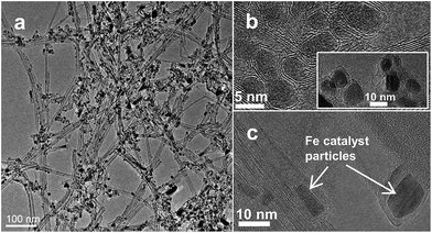
A one-step floating catalyst (aerosol) CVD synthesis was utilized to grow the CEIN/CNT material (see synthesis details in the ESI and Fig. S1†). This synthesis process has been recently used to produce highly conductive transparent films31 and active catalyst materials for the hydrogen evolution reaction.26 Shortly, an aerosolized feedstock solution of ferrocene (C10H10Fe) and thiophene (C4H4S) in toluene (C7H8) was introduced into a heated quartz tube. Ferrocene was decomposed to Fe nanoparticles at a high temperature. Toluene and ethylene (C2H4) were the carbon sources for the CNT synthesis. The utilization of hydrocarbons results in a high reaction yield which is a key parameter for industrial applications.31Fig. 1 shows transmission electron microscopy (TEM) images of the synthesized material in which we can see a mixture of CNTs and CEINs decorated on the CNTs. Iron nanoparticles used for the growth of CEINs and CNTs are shown in high-resolution TEM (HRTEM) images in Fig. 1b and c, respectively.After the decomposition of ferrocene, toluene and ethylene in the reactor, in the nucleation process of CNTs, graphene layers first appear around the metal clusters. Subsequently, the metal cluster assumes a conical shape and forms the characteristic protrusion, which expels a CNT and, then, elongates by the large forces exerted by the surrounding carbon tubes. In our sample, we observed (Fig. S2†) iron particles at different CNT growth steps from carbon-enclosed particles to particles with conical shapes and elongated particles surrounded by CNTs. The CEINs might be synthesized at the end of the hot zone of the reactor where they do not have enough time to form CNTs. This growth mechanism of CNTs and CEINs is suggested on the basis of earlier in situ observations for the growth of CNTs.32–34 The growth is highly dependent on the amount of iron source as, according to our earlier observations, the amount of CEINs will be decreased dramatically when the concentration of ferrocene is decreased.31 Size distribution analysis of Fe nanoparticles in CEINs (Fig. S3†) was performed from the HRTEM images of the CEIN/CNT sample and resulted in an average size of 5.4 nm for the carbon encapsulated metallic iron nanoparticles.
The catalytic activity of the CEIN/CNT catalyst for the OER was evaluated using a standard three-electrode electrochemical configuration in aqueous NaOH purged with N2 (see details of electrochemical procedures in the ESI†). Fig. S4† shows the first five OER sweeps for the CEIN/CNT sample in alkaline 0.1 and 1 M NaOH solutions, indicating that the current is almost stabilized after 3 anodic sweeps. The higher current in the first sweeps is attributed to the oxidation of carbon and iron. The following discussions show that during a few cycles in the OER potential region in an alkaline solution the CEIN/CNT material is converted to γ-Fe2O3/CNTs. This material exhibits high and stable catalytic activity for the OER.
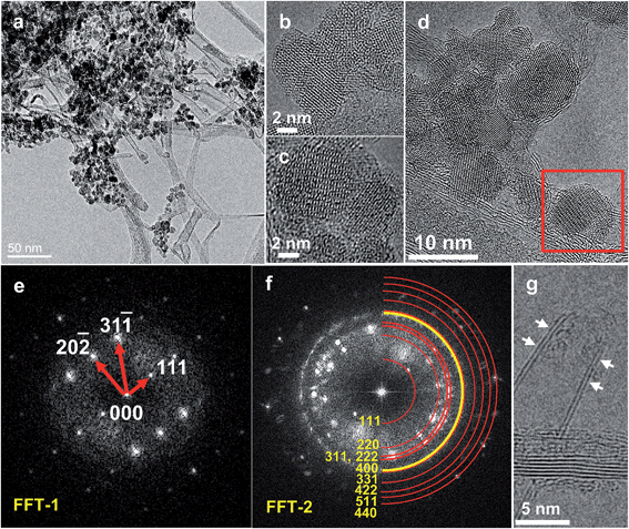
Fig. 2 displays TEM images taken from the CEIN/CNT material after the stabilization of the OER current in 0.1 M NaOH by the continuous potential cycling between 1.0 and 1.65 V vs. reversible hydrogen electrode (RHE). Compared to Fig. 1 for the initial CEIN/CNT sample, it is visible that the graphene layers surrounding Fe nanoparticles in CEINs are diminished here. The TEM crystallographic investigations based on experimental and simulated electron diffraction ring patterns (Fig. 2e and f) clearly indicate that the uncovered nanoparticles are maghemite (γ-Fe2O3). These results exhibit that the CEINs with pure Fe metallic cores have been transformed to γ-Fe2O3 nanoparticles after the potential cycling. Fig. 2g indicates that although the graphite structure of the surface of the CNTs is preserved the hemispherical end-caps of the CNTs have also been opened by the continuous cycling in the alkaline solution. The presence of pentagonal rings and the great strain on the carbon atoms at the hemispherical tips of the CNTs and graphene layers surrounding the Fe particles in CEINs make them more reactive compared to the hexagonal structure of the sidewalls of the CNTs.35 This causes the caps of the CNTs and carbon cages around the Fe nanoparticles to selectively react with hydroxide (OH−) ions in the alkaline solution and thus they are stripped off. Subsequently, hydroxide ions react with the iron nanoparticles to form γ-Fe2O3 nanoparticles. Size distribution analysis of the γ-Fe2O3 nanoparticles (Fig. S5†) was performed from the HRTEM images of the γ-Fe2O3/CNT sample and resulted in an average size of 6.3 nm for the nanoparticles. The observed growth in the size of the nanoparticles is expected as oxygen is incorporated in the lattice of the metallic iron.
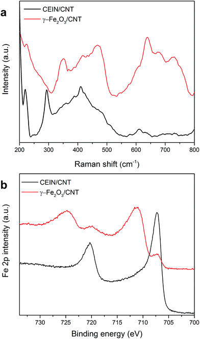
Raman spectroscopy of the CEIN/CNT and the γ-Fe2O3/CNT samples (Fig. S6†) revealed an increase of the relative amount of disordered carbon atoms as the ratio of D and G band intensities (ID/IG) increased from 0.37 in the initial CEIN/CNT sample to 0.88 after current stabilization upon the above-mentioned repeated OER sweeps (see details of Raman data in the ESI†). The increase in ID/IG is attributed to the presence of oxygen-containing groups on the CNT surface formed during the electrochemical treatment. However, the change in polarization curves cannot be attributed to the CNTs, since repeated potential cycling of pristine CNTs in the alkaline solution in the similar potential range has not shown any significant change in the OER polarization curves compared to the pristine CNTs.23 After the OER current of CEIN/CNT is stabilized and γ-Fe2O3/CNTs is formed, Raman spectra at the low-frequency region (Fig. 3a) display the appearance of new features mainly at around 350 and 700 cm−1 which are attributed to the Raman active modes of maghemite, Eg and A1g, respectively.36,37
Fig. 3b and S7† demonstrate spectra taken by X-ray photoelectron spectroscopy (XPS) of the CEIN/CNT sample before and after 3 OER sweeps (anodic potential sweeps between 1.0 and 1.65 V) at a scan rate of 5 mV s−1 and a rotation of 1600 rpm in 1 M NaOH. In addition, the corresponding elemental compositions are represented in Table S1.† In Fig. 3, there are two main peaks at binding energies of ∼707 and ∼720 eV for CEIN/CNT which were ascribed to the metallic Fe 2p3/2 and Fe 2p1/2 peaks, respectively. However, after 3 OER sweeps only a small amount of pure metallic Fe in the XPS spectrum was detected and additional Fe 2p3/2 and Fe 2p1/2 peaks were detected at 711.2 and 724.7 eV, respectively, which are similar to the values reported for maghemite (γ-Fe2O3) nanoparticles in the literature.38–40 These results further evidence that the metallic iron and the surrounding carbon layers are oxidized during the electrochemical treatment.
Fig. S8† shows cyclic voltammetry (CV) curves of the CEIN/CNT electrode before and after cycling the potential of the electrode between 1.0 and 1.65 V until the OER current is stabilized and γ-Fe2O3/CNTs are formed. In the active region of iron (between −0.45 and 0.45 V) two main anodic and cathodic peaks of iron at ∼0.25 (peak I) and ∼−0.11 V (peak II) appear. These peaks come from reversible redox reactions of the uncovered iron particles:41,42
| Peak I: Fe(OH)2 → FeOOH |
| Peak II: FeOOH → Fe(OH)2 |
The intensities of these peaks were weak in the initial CEIN/CNT sample since most of the iron particles are covered by graphene layers. After the potential cycling, the faradaic currents increase dramatically in the active region, attributed to the activation of iron oxide nanoparticles as a consequence of the removal of the carbon cages surrounding Fe nanoparticles in the CEINs.
Nieuwoudt et al. investigated the composition of the passive film formed on iron in 0.05 M NaOH by in situ Raman microspectroscopy.42 They indicated that after potential cycling in NaOH solution α-FeOOH, γ-FeOOH, δ-FeOOH and γ-Fe2O3 are the possible forms of the passive layers on iron. However, they have shown that the main passive layer is γ-Fe2O3 if the voltage applied to iron is close to the OER potential range. These results are in agreement with the above presented results based on HRTEM, XPS and Raman analysis, showing that after voltammetric cycling of the carbon enclosed Fe nanoparticles between 1.0–1.65 V (the potential range close to the OER scan), the Fe particles in the CEIN/CNT sample are converted mainly to γ-Fe2O3.
2.2. Oxygen evolution activity and discussion
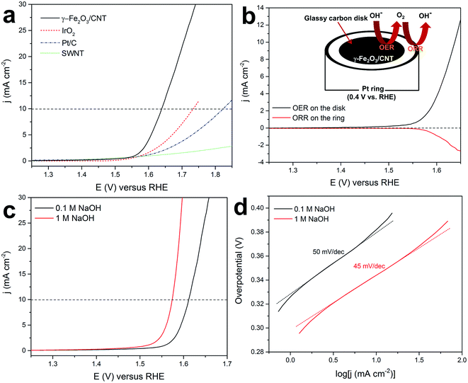
As explained before and shown in Fig. S9,† γ-Fe2O3/CNTs were obtained by sweeping or cycling the potential applied to the CEIN/CNT electrode continuously between 1 and 1.65 V vs. RHE in NaOH until stabilized current for the OER was established. Fig. 4a shows typical rotating disk electrode (RDE) polarization curves of the OER on the stabilized γ-Fe2O3/CNT sample compared to single-walled carbon nanotubes (SWNTs), Pt/C, and IrO2 electrodes in 0.1 M NaOH. The γ-Fe2O3/CNT material exhibited a high OER catalytic activity with an onset overpotential of merely 300 mV (the thermodynamic oxygen evolution potential is 1.23 V vs. RHE) in 0.1 M NaOH. All the measured catalysts were deposited on a glassy carbon electrode with a similar loading of ∼0.2 mg cm−2.The current observed in the high applied potential range can result from a four electron transfer reaction resulting in oxygen evolution or from an unwanted two electron transfer reaction resulting in hydrogen peroxide formation. On the other hand, oxidation of the CNT support as a side reaction can also take place. To investigate the efficiency of the OER, the oxygen evolution at γ-Fe2O3/CNTs is also monitored with a rotating ring disk electrode (RRDE) in nitrogen-saturated 0.1 M NaOH.5,8,23 In RRDE measurements, the evolved oxygen at the disk was then reduced at the surrounding Pt ring electrode that was held at 0.4 V. Fig. 4b shows that at the potentials above the onset of the OER (1.53 V) for the disk electrode, the current attributed to the oxygen reduction reaction (ORR) at the Pt ring electrode is detected, indicating the evolution and the following reduction of oxygen at the disc and ring electrodes, respectively. The RRDE measurements can be also used for quickly screening the approximate Faradaic efficiency of O2 production (ε), by the equation of jORR/jOER × N, where jORR and jOER are current densities measured on the Pt ring and on the glassy carbon disc, respectively, and N is the collection efficiency of the RRDE.8,13,23 In general, ε > 90% for the OER at different measurements on the γ-Fe2O3/CNT catalyst was obtained in 0.1 M NaOH. It should be noted that small errors in the ring current and collection efficiency can lead to relatively large errors in ε, but RRDE measurements are still useful for rapidly screening the approximate faradaic efficiency.8 By changing the ring electrode potential to 1.4 V, the generation of H2O2 was monitored. Through this measurement, no detectable current from H2O2 oxidation at the Pt ring was observed, indicating that H2O2 is not produced on the disc electrode (Fig. S10†). These results confirmed that the water oxidation at the γ-Fe2O3/CNT electrode proceeds via a 4-electron transfer process to generate dioxygen (the OER pathway: 4OH− → O2 + 2H2O + 4e−).
Fig. 4c demonstrates OER polarization curves with iR compensation obtained with γ-Fe2O3/CNTs in 0.1 and 1 M NaOH. The potentials required to obtain a current density of 10 mA cm−2 are measured to be 1.61 and 1.57 V in 0.1 and 1 M NaOH, respectively. These values are comparable to the recently reported highly active transition-/noble-metal and non-metal catalysts for the OER (see Table S2†). Fig. 1d shows the Tafel plots of γ-Fe2O3/CNTs in the OER derived from Fig. 1c. γ-Fe2O3/CNTs resulted in Tafel slopes of 50 and 45 mV per decade in 0.1 and 1 M NaOH, respectively, which are smaller than the values recently reported for carbon and/or metal hybrids.13,19,43,44 The Tafel plots with good linearity and small slopes imply that γ-Fe2O3/CNTs are an efficient catalyst for the OER with a high electrical conductivity for fast electron transfer. Hence, γ-Fe2O3/CNTs are introduced as a novel non-precious catalyst for the OER with an activity that rivals the most active reported electrocatalysts for the OER (Table S2†).
The electrochemically active surface area (ECSA) of the γ-Fe2O3/CNT catalyst was estimated from the electrochemical double-layer capacitance of the catalytic surface8,23 (see Calculation details in the ESI†). The double-layer capacitance was calculated from the non-faradaic capacitive current associated with the charging current measured from the cyclic voltammograms (CVs) at different scan rates (Fig. S11†).8,23,45 The ECSA and roughness factor (RF) of the γ-Fe2O3/CNT catalyst were estimated to be 35 cm2 and 280, respectively, which are significantly higher than the corresponding values of the previously reported highly active catalysts for the OER,8,23 indicating a large active surface area contributing to the high activity of the investigated electrocatalyst.
Previous studies have resulted in poor OER catalytic activity for hematite (α-Fe2O3),12 Fe films10 and modified CNTs with Fe2O3 (probably α-Fe2O3) nanoparticles.23 Recently, the synthesis of maghemite nanorods anchored on 3D nitrogen doped carbon nanotubes showed an improvement in the activity of iron oxide for OER electrocatalytic activity, although the activity was still significantly lower than the highly reported active electrocatalysts for the OER.46 In contrast, we observed a high OER catalytic activity for γ-Fe2O3 nanoparticles decorated on the CNTs. The high OER activity in our catalyst is attributed to the maghemite (γ-Fe2O3) nanoparticles compared to hematite (α-Fe2O3), and very high ECSA of the γ-Fe2O3/CNT catalyst synthesized in this work as well as high conductivity of the catalyst brought by the CNT support.
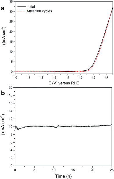
For the γ-Fe2O3/CNT electrode, stability tests were performed in 0.1 M NaOH by cycling the potential between 1 and 1.75 V at a scan rate of 50 mV s−1 (Fig. 5a) and measuring the time dependence of the current density at a static potential of 1.64 V where the current density is ∼10 mA cm−2 (Fig. 5b). The upper limit for cycling stability measurements (1.75 V) corresponds roughly to a current density of ∼30 mA cm−2. The OER polarization curves of γ-Fe2O3/CNTs before and after 100 potential cycles (Fig. 5a) revealed no observable degradation in the OER activity and, as shown above (see TEM images in Fig. 2 which were taken after the stability measurements), the γ-Fe2O3 nanoparticles are still well dispersed on the CNT support. Likewise, the chronoamperometric curve (Fig. 5b) showed that the current density remains stable, apart from a small fluctuation in the current, during the course of the water electrolysis. This fluctuation is attributed to oxygen gas bubbles formed by molecular oxygen evolved in the reaction. These hydrophobic gas bubbles are prone to attach on the electrocatalyst surface resulting in temporary blocking of the active surface sites until they grow large enough and are detached form the surface, resulting in the observed fluctuation in the current. These results indicate that γ-Fe2O3/CNTs are stable and active electrocatalysts for the OER in alkaline media.
Electrochemical purification is an efficient way to purify CNTs from iron impurities.47 To observe the contribution of CNTs in the OER activity of the CEIN/CNT sample, we electrochemically purified the CEIN/CNT sample from iron impurities through 5 potential cycles between 1 and 1.6 V vs. RHE in 0.5 M H2SO4 at a scan rate of 50 mV s−1. TEM images from the CEIN/CNT material after purification (Fig. S12†) indicate the removal of iron impurities from the surface of the CNTs. Furthermore, the HRTEM images from the purified sample demonstrate that this electrochemical purification opens the caps of the CNTs while the structure of the sidewalls of the CNTs is preserved. After purification, CNTs confirmed negligible OER catalytic activity in 0.1 M NaOH alkaline solution, compared to the γ-Fe2O3/CNT catalyst (Fig. S13†). Therefore, the high catalytic activity in γ-Fe2O3/CNTs is associated solely to the γ-Fe2O3 nanoparticles decorated on the CNT support.
3. Conclusions
In summary, the CEIN/CNT material is synthesized by a fast and low cost floating catalyst CVD method in a one-step synthesis with a similar growth process to that of the CNTs. By cycling or sweeping the potential applied to the CEIN/CNT electrode, carbon cages in CEINs and the caps of the CNTs are selectively stripped off from the electrode. Subsequently, γ-Fe2O3 nanoparticles decorated on the CNTs (γ-Fe2O3/CNTs) are formed with high activity and durability for catalyzing the OER, comparable to the most active OER electrocatalysts. This study shows for the first time that iron oxide can be used directly as a highly active electrocatalyst material for the OER. Our findings open the door to new OER catalyst materials synthesized by modifying the growth process of CNTs as one of the most interesting materials in science and industry. The unique electrical and magnetic properties of maghemite nanoparticles can also expand the potential applications of this material.Acknowledgements
This work is supported by Aalto University (MOPPI project in AEF program) and Academy of Finland (the DEMEC and SUPER projects). This work made use of the Aalto University Nanomicroscopy Center (Aalto-NMC) premises.References
- M. G. Walter, E. L. Warren, J. R. McKone, S. W. Boettcher, Q. Mi, E. A. Santori and N. S. Lewis, Chem. Rev., 2010, 110, 6446–6473 CrossRef CAS PubMed.
- T. R. Cook, D. K. Dogutan, S. Y. Reece, Y. Surendranath, T. S. Teets and D. G. Nocera, Chem. Rev., 2010, 110, 6474–6502 CrossRef CAS PubMed.
- N. S. Lewis and D. G. Nocera, Proc. Natl. Acad. Sci. U. S. A., 2006, 103, 15729–15735 CrossRef CAS PubMed.
- M. Gong and H. Dai, Nano Res., 2015, 8, 23–39 CrossRef CAS.
- J. Suntivich, K. J. May, H. A. Gasteiger, J. B. Goodenough and Y. Shao-Horn, Science, 2011, 334, 1383–1385 CrossRef CAS PubMed.
- Y. Lee, J. Suntivich, K. J. May, E. E. Perry and Y. Shao-Horn, J. Phys. Chem. Lett., 2012, 3, 399–404 CrossRef CAS PubMed.
- T. Reier, M. Oezaslan and P. Strasser, ACS Catal., 2012, 2, 1765–1772 CrossRef CAS.
- C. C. L. McCrory, S. Jung, J. C. Peters and T. F. Jaramillo, J. Am. Chem. Soc., 2013, 135, 16977–16987 CrossRef CAS PubMed.
- L. Trotochaud, J. K. Ranney, K. N. Williams and S. W. Boettcher, J. Am. Chem. Soc., 2012, 134, 17253–17261 CrossRef CAS PubMed.
- M. W. Louie and A. T. Bell, J. Am. Chem. Soc., 2013, 135, 12329–12337 CrossRef CAS PubMed.
- M. Ledendecker, G. Clavel, M. Antonietti and M. Shalom, Adv. Funct. Mater., 2015, 25, 393–399 CrossRef CAS.
- R. D. L. Smith, M. S. Prévot, R. D. Fagan, Z. Zhang, P. A. Sedach, M. K. J. Siu, S. Trudel and C. P. Berlinguette, Science, 2013, 340, 60–63 CrossRef CAS PubMed.
- T. Y. Ma, S. Dai, M. Jaroniec and S. Z. Qiao, J. Am. Chem. Soc., 2014, 136, 13925–13931 CrossRef CAS PubMed.
- W. Zhou, X.-J. Wu, X. Cao, X. Huang, C. Tan, J. Tian, H. Liu, J. Wang and H. Zhang, Energy Environ. Sci., 2013, 6, 2921–2924 CAS.
- Z. Zhao, H. Wu, H. He, X. Xu and Y. Jin, Adv. Funct. Mater., 2014, 24, 4698–4705 CrossRef CAS.
- Y. Yang, H. Fei, G. Ruan, C. Xiang and J. M. Tour, ACS Nano, 2014, 8, 9518–9523 CrossRef CAS PubMed.
- X. Lu and C. Zhao, J. Mater. Chem. A, 2013, 1, 12053–12059 CAS.
- K. Mette, A. Bergmann, J.-P. Tessonnier, M. Hävecker, L. Yao, T. Ressler, R. Schlögl, P. Strasser and M. Behrens, ChemCatChem, 2012, 4, 851–862 CrossRef CAS.
- S. Dou, L. Tao, J. Huo, S. Wang and L. Dai, Energy Environ. Sci., 2016 10.1039/c6ee00054a.
- Y. Liang, Y. Li, H. Wang and H. Dai, J. Am. Chem. Soc., 2013, 135, 2013–2036 CrossRef CAS PubMed.
- G. G. Wildgoose, C. E. Banks and R. G. Compton, Small, 2006, 2, 182–193 CrossRef CAS PubMed.
- W. Zhang, P. Sherrell, A. I. Minett, J. M. Razal and J. Chen, Energy Environ. Sci., 2010, 3, 1286–1293 CAS.
- X. Lu, W.-L. Yim, B. H. R. Suryanto and C. Zhao, J. Am. Chem. Soc., 2015, 137, 2901–2907 CrossRef CAS PubMed.
- Y. Cheng, C. Xu, L. Jia, J. D. Gale, L. Zhang, C. Liu, P. K. Shen and S. P. Jiang, Appl. Catal., B, 2015, 163, 96–104 CrossRef CAS.
- M. Gong, Y. Li, H. Wang, Y. Liang, J. Z. Wu, J. Zhou, J. Wang, T. Regier, F. Wei and H. Dai, J. Am. Chem. Soc., 2013, 135, 8452–8455 CrossRef CAS PubMed.
- M. Tavakkoli, T. Kallio, O. Reynaud, A. G. Nasibulin, C. Johans, J. Sainio, H. Jiang, E. I. Kauppinen and K. Laasonen, Angew. Chem., Int. Ed., 2015, 54, 4535–4538 CrossRef CAS PubMed.
- X. Zou, X. Huang, A. Goswami, R. Silva, B. R. Sathe, E. Mikmeková and T. Asefa, Angew. Chem., 2014, 126, 4461–4465 CrossRef.
- J. Deng, P. Ren, D. Deng and X. Bao, Angew. Chem., Int. Ed., 2015, 54, 2100–2104 CrossRef CAS PubMed.
- J. Wang, G. Wang, S. Miao, J. Li and X. Bao, Faraday Discuss., 2014, 176, 135–151 RSC.
- Y. Hu, J. O. Jensen, W. Zhang, L. N. Cleemann, W. Xing, N. J. Bjerrum and Q. Li, Angew. Chem., Int. Ed., 2014, 53, 3675–3679 CrossRef CAS PubMed.
- O. Reynaud, A. G. Nasibulin, A. S. Anisimov, I. V. Anoshkin, H. Jiang and E. I. Kauppinen, Chem. Eng. J., 2014, 255, 134–140 CrossRef CAS.
- H. Yoshida, S. Takeda, T. Uchiyama, H. Kohno and Y. Homma, Nano Lett., 2008, 8, 2082–2086 CrossRef CAS PubMed.
- M. Kumar, Carbon Nanotube Synthesis and Growth Mechanism, InTech, 2011 Search PubMed.
- C. T. Wirth, S. Hofmann and J. Robertson, Diamond Relat. Mater., 2009, 18, 940–945 CrossRef CAS.
- P. M. Ajayan, T. W. Ebbesen, T. Ichihashi, S. Iijima, K. Tanigaki and H. Hiura, Nature, 1993, 362, 522–525 CrossRef CAS.
- A. M. Jubb and H. C. Allen, ACS Appl. Mater. Interfaces, 2010, 2, 2804–2812 CAS.
- D. L. A. de Faria, S. Venâncio Silva and M. T. de Oliveira, J. Raman Spectrosc., 1997, 28, 873–878 CrossRef CAS.
- T. Hyeon, S. S. Lee, J. Park, Y. Chung and H. B. Na, J. Am. Chem. Soc., 2001, 123, 12798–12801 CrossRef CAS PubMed.
- H. Park, P. Ayala, M. A. Deshusses, A. Mulchandani, H. Choi and N. V. Myung, Chem. Eng. J., 2008, 139, 208–212 CrossRef CAS.
- Z. Sun, Z. Liu, Y. Wang, B. Han, J. Du and J. Zhang, J. Mater. Chem., 2005, 15, 4497–4501 RSC.
- A. H. L. Goff, J. Flis, N. Boucherit, S. Joiret and J. Wilinski, J. Electrochem. Soc., 1990, 137, 2684–2690 CrossRef.
- M. K. Nieuwoudt, J. D. Comins and I. Cukrowski, J. Raman Spectrosc., 2011, 42, 1353–1365 CrossRef CAS.
- T. Y. Ma, S. Dai, M. Jaroniec and S. Z. Qiao, Angew. Chem., Int. Ed., 2014, 53, 7281–7285 CrossRef CAS PubMed.
- S. Mao, Z. Wen, T. Huang, Y. Hou and J. Chen, Energy Environ. Sci., 2014, 7, 609–616 CAS.
- J. D. Benck, Z. Chen, L. Y. Kuritzky, A. J. Forman and T. F. Jaramillo, ACS Catal., 2012, 2, 1916–1923 CrossRef CAS.
- T. Sharifi, W. L. Kwong, H.-M. Berends, C. Larsen, J. Messinger and T. Wågberg, Int. J. Hydrogen Energy, 2016, 41, 69–78 CrossRef CAS.
- A. Heras, A. Colina, J. López-Palacios, P. Ayala, J. Sainio, V. Ruiz and E. I. Kauppinen, Electrochem. Commun., 2009, 11, 1535–1538 CrossRef CAS.
Footnote |
| † Electronic supplementary information (ESI) available: Materials synthesis, electrochemical procedures, ECAS calculations, TEM images, Raman spectroscopy, XPS, RDE and RRDE measurements, CV curves, and supporting data. See DOI: 10.1039/c6ta01472k |
| This journal is © The Royal Society of Chemistry 2016 |

