
 Open Access Article
 This Open Access Article is licensed under a
 Creative Commons Attribution 3.0 Unported Licence
Optimized light-driven electrochemical water splitting with tandem polymer solar cells†
Serkan
Esiner
a,
Gijs W. P.
van Pruissen
a,
Martijn M.
Wienk
ab and
René A. J.
Janssen
*ab
aMolecular Materials and Nanosystems, Institute for Complex Molecular Systems, Eindhoven University of Technology, P. O. Box 513, 5600 MB Eindhoven, The Netherlands. E-mail: r.a.j.janssen@tue.nl
bDutch Institute for Fundamental Energy Research, De Zaale 20, 5612 AJ Eindhoven, The Netherlands
First published on 3rd March 2016
Abstract
Tandem polymer solar cells are used for light-driven electrochemical water splitting. To attain a high enough electrochemical potential a new wide band gap electron donor polymer (PTPTIBDT-OD) is developed and used in combination with [70]PCBM as an electron acceptor in a tandem device architecture with two identical photoactive layers. This homo-tandem device comprises an intermediate ZnO/PEDOT:PSS/MoO3 charge recombination layer to connect the two subcells electrically and optically. The homo-tandem solar cell has an open-circuit voltage of 1.74 V and reaches a power conversion efficiency (PCE) of 5.3%. In combination with RuO2 as the electrocatalyst for oxygen evolution and RuO2 or Pt catalysts for hydrogen evolution, sunlight-driven electrochemical water splitting occurs with a solar-to-hydrogen conversion efficiency of ηSTH = 4.3%. Owing to the very high fill factor of the polymer tandem cell (0.73), water splitting takes place near the maximum power point of the homo-tandem solar cell. As a consequence, the difference between PCE and ηSTH is only due to the overpotential losses.
Introduction
Electrochemical water splitting occurs at a standard potential of 1.23 V but in practice substantially higher potentials (1.4 to 1.8 V) are required due to overpotentials for the hydrogen and oxygen evolution reactions. As a consequence, sunlight-driven electrochemical water splitting devices use multi-junction cell configurations in which two or more photovoltaic cells are stacked and connected in series to reach the high potential while still using an appreciable part of the solar spectrum. Triple junction stacks of amorphous silicon solar cells are often used for light-driven electrochemical water splitting purposes, because the summed voltage of the three cells provides the required potential.1–4 Recently, we demonstrated that triple junction polymer-fullerene solar cells can also be used successfully for this purpose.5,6 If the water splitting potential is sufficiently reduced by using appropriate catalysts for hydrogen and oxygen evolution, tandem solar cells may also be used.7,8 This is beneficial in terms of device fabrication, because there is one less junction and photoactive layer, and also in terms of the overall solar-to-hydrogen conversion efficiency. In principle, a tandem solar cell can generate up to 50% higher current density than a triple junction cell at the same optical band gap,7 because the photon flux is distributed over only two instead of three absorber layers. Provided that the required electrochemical potential is achieved, the solar to hydrogen conversion efficiency (ηSTH) only depends on the current density of the solar cell during operation. Hence tandem cells offer an advantage. Of course, the electrochemical potential for sunlight-driven electrochemical water splitting poses a lower threshold for the optical band gap of the semiconductors that can be used. The minimum optical band gap is higher for tandem cells than that for triple junction cells, and this limits the use of the complete solar spectrum.In our recent example of a water splitting device, a triple junction polymer solar cell operating at a voltage of 1.49 V was used in combination with RuO2 electrocatalysts for hydrogen and oxygen evolution.6 A tandem solar cell that is intended to split water at this potential requires an open-circuit voltage (Voc) of about 1.75 V and only a few examples of polymer tandem solar cells with such high Voc exist, using absorber layers with a wide optical band gap.5,9–11 The higher Voc is generally achieved at the cost of lower current densities and wide band gap materials that can provide high current densities are scarce.12,13
One approach towards a high voltage tandem cell is a device configuration in which both photoactive layers are composed of the same wide band gap material. These homo-tandem cells can provide higher efficiencies compared to the corresponding single junction devices because of improved absorption of light and enhanced charge collection.9,14–16 When light is distributed over two identical but thinner layers, light absorption can be equally high as in one thick layer, but bimolecular recombination of charges decreases because the distance over which charges are collected is reduced,9 resulting in an overall higher efficiency.
In this paper we demonstrate light-driven electrochemical water splitting using a series connected tandem polymer solar cell. In order to achieve a sufficiently high Voc, a new wide band gap material PTPTIBDT-OD (poly(4,10-(2-octyldodecyl)-4,10-dihydrothieno[2′,3′:5,6]-pyrido[3,4-g]thieno[3,2-c]isoquinoline-5,11-dione)-co-benzo[1,2-b:4,5-b′]dithiophene, Fig. 1) has been developed. The polymer comprises an electron deficient pentacyclic lactam unit that was recently introduced in donor–acceptor conjugated copolymers to afford optical band gaps higher than 1.7 eV in combination with a Voc of about 0.9 V, when copolymerized with different π-conjugated donors.17–20 To ensure a loss free series connection of the two subcells, we introduce a ZnO/PEDOT:PSS/MoO3 stack as the intermediate recombination layer. Light-driven electrochemical water splitting performed with RuO2–RuO2 and RuO2–Pt electrodes in 1.0 M KOH electrolyte shows a solar to hydrogen conversion efficiency of ∼4.3%.
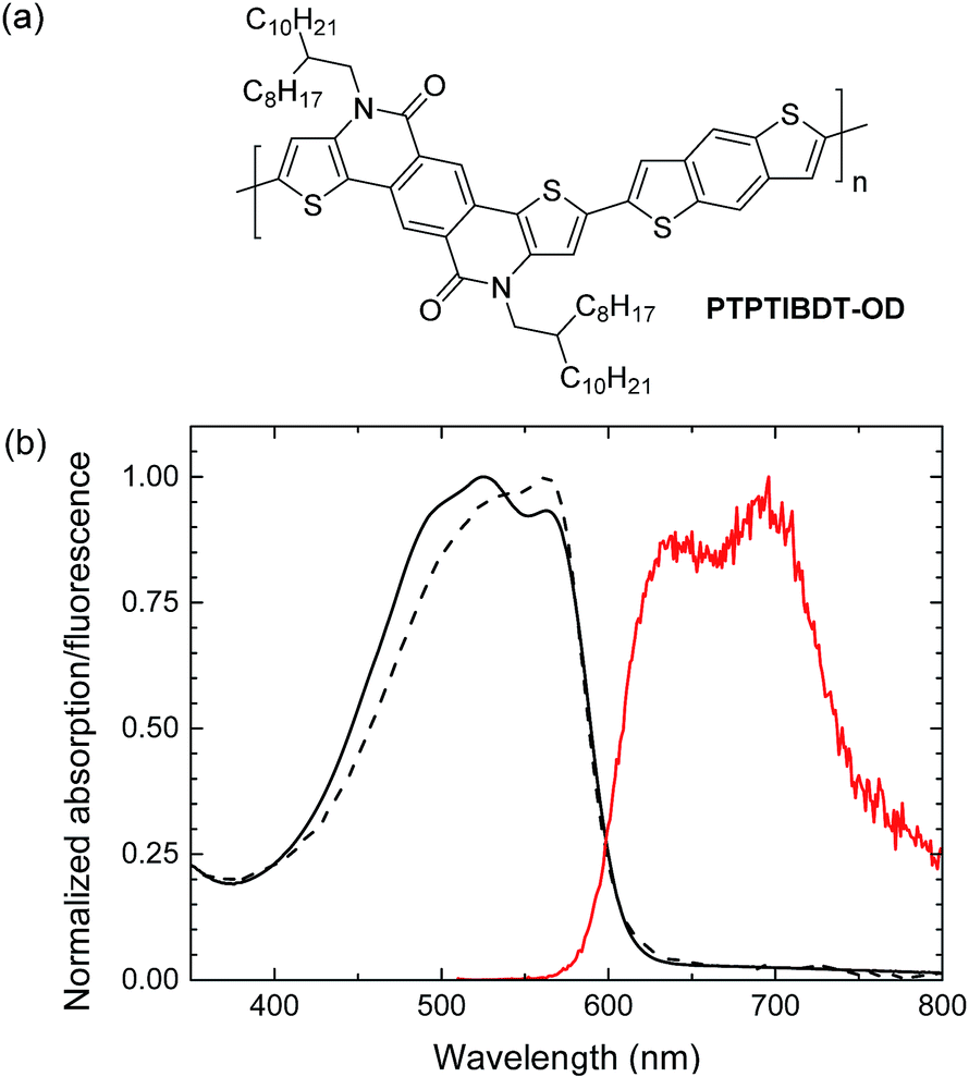 | ||
| Fig. 1 (a) Structure of PTPTIBDT-OD. (b) UV-vis absorption (black) and fluorescence (red) spectra of PTPTIBDT-OD in chloroform solution (dashed line) and as thin film (solid lines). | ||
Results and discussion
Synthesis and characterization
PTPTIBDT-OD was synthesized by a Stille polymerization of 2,8-dibromo-4,10-di(2-octyldodecyl)-4,10-dihydrothieno[2′,3′:5,6]-pyrido[3,4-g]thieno[3,2-c]isoquinoline-5,11-dione with 2,6-bis(trimethylstannyl)benzo[1,2-b:4,5-b′]dithiophene as described in detail in the ESI.† The resulting polymer had a Mn = 35.4 kg mol−1. The optical band gap (Eg) of PTPTIBDT-OD is 2.04 eV as determined from the onset of absorption in chloroform solution and thin film (Fig. 1). PTPTIBDT-OD shows a weak fluorescence at 642 nm (1.93 eV) with a vibronic progression towards lower energies. The oxidation and reduction potentials of PTPTIBDT-OD were measured using cyclic voltammetry on spin-coated thin films on ITO covered glass substrates in acetonitrile containing 0.1 M TBAPF6 as the electrolyte, resulting in estimates for the frontier orbital energy levels of EHOMO = −5.75 eV and ELUMO = −3.19 eV. The electrochemical band gap, ECVg = 2.56 eV, is significantly larger than the optical band gap.Single and tandem junctions
When blended with [70]PCBM ([6,6]-phenyl-C71-butyric acid methyl ester), a single junction solar cell of PTPTIBDT-OD provides a Voc of 0.90 V in a cell configuration with transparent ITO/PEDOT:PSS bottom and reflective LiF/Al top electrodes. The optimized single junction PTPTIBDT-OD:[70]PCBM cell has a PCE of about 5.2% (Table 1). The J–V characteristics and the EQE measurement of this cell are shown in Fig. 2. The short-circuit current density (Jsc) determined from the EQE after integration with the AM1.5 G solar spectrum amounts to Jsc = 8.38 mA cm−2 and is slightly larger than the one determined from the J–V characteristics (Jsc = 8.19 mA cm−2). The optimized cell has a notably high fill factor (0.70) which places the voltage of the maximum power point (Vmax = 0.73 V) close to Voc (0.90 V). Optimized PTPTIBDT-OD:[70]PCBM films show narrow fibre-like structures and crystalline regions in transmission electron microscopy (TEM) images (Fig. 3). With such a high fill factor, a homo-tandem solar cell of the PTPTIBDT-OD:[70]PCBM blend can have a high voltage at the maximum power point, sufficient for light-driven electrochemical water splitting. However, reaching a sufficiently high voltage in a tandem configuration is not trivial. The reason is the nature of the recombination contact. In the frequently used recombination contact of a bilayer of ZnO and pH neutral PEDOT:PSS,21 the pH neutral PEDOT:PSS layer, which serves as the hole extracting contact for the back cell, has a lower work function (4.65 eV) than that of the common, highly acidic, PEDOT:PSS (5.05 eV).22 The reduced work function limits the maximum voltage of the second subcell. The use of pH neutral PEDOT:PSS is dictated by the high solubility of ZnO in water at a low pH, which prevents spin coating acidic PEDOT:PSS on top of a ZnO layer.21 If the back cell uses a polymer with a deep HOMO level to reach a high Voc, the large difference between the low work function of pH neutral PEDOT:PSS and the deep HOMO of the polymer causes a non-ohmic contact and introduces losses in the Voc of the back cell.5,22 A partial solution for increasing the work function of pH neutral PEDOT:PSS is spin coating a thin Nafion layer on top.5,22 However, a considerable portion of the lost voltage still remains to be recovered after adding the Nafion layer.5,22| Device | Hole transport layer in the recombination contact | J sc [mA cm−2] | V oc (V) | FF | PCE (%) |
|---|---|---|---|---|---|
| Single | 8.19 | 0.90 | 0.70 | 5.2 | |
| Tandem | pH neutral PEDOT:PSS | 3.84 | 1.53 | 0.69 | 4.0 |
| Tandem | pH neutral PEDOT:PSS + Nafion | 3.91 | 1.58 | 0.64 | 3.9 |
| Tandem | pH neutral PEDOT:PSS + MoO3 | 3.91 | 1.72 | 0.75 | 5.0 |
| Tandem optimized | pH neutral PEDOT:PSS + MoO3 | 4.19 | 1.74 | 0.73 | 5.3 |
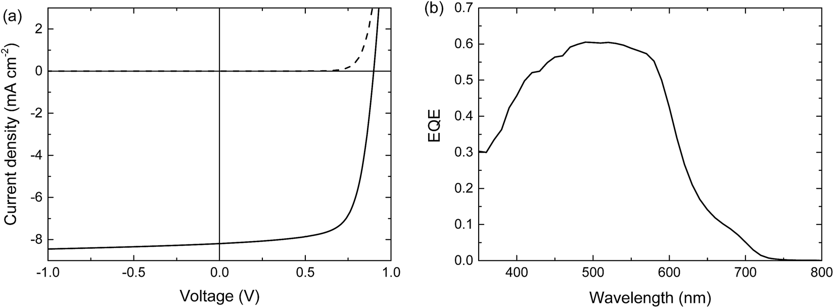 | ||
| Fig. 2 Optimized single junction PTPTIBDT-OD:[70]PCBM solar cell. (a) J–V characteristics under the dark (dashed line) and simulated AM1.5 G illumination (solid line). (b) EQE. | ||
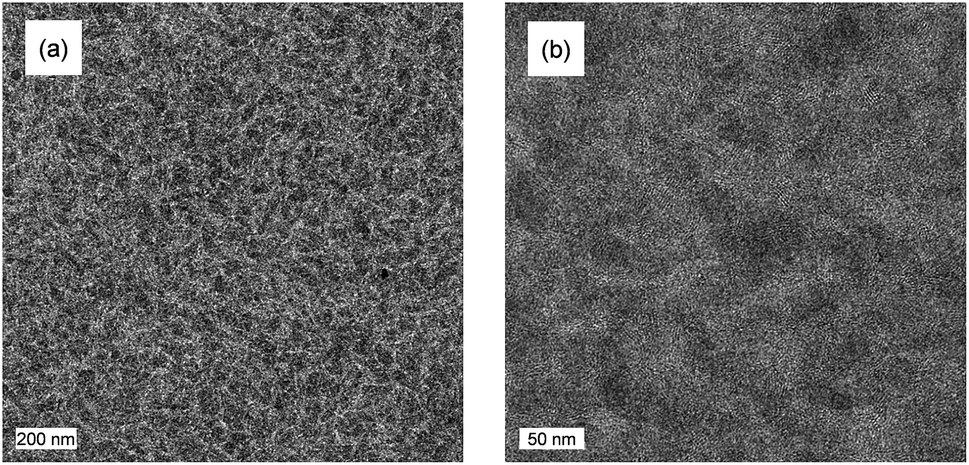 | ||
| Fig. 3 TEM images showing the morphology of the optimized photoactive layers; scale bars are 200 nm (a) and 50 nm (b). | ||
Another approach to improve the work function of pH neutral PEDOT:PSS is depositing a thin layer of molybdenum oxide (MoO3) onto pH neutral PEDOT:PSS by thermal evaporation. Evaporated MoO3 is a well-known hole collector that can replace PEDOT:PSS in normal configuration single junctions.23 Because of its high work function (5.40 eV), MoO3 is expected to prevent voltage losses in high voltage back cells. MoO3 is also commonly used as a hole extracting contact in inverted single junction cell configurations.24,25 Yang et al. have also used MoO3 in the intermediate contact of an inverted tandem solar cell.16
Homo-tandem PTPTIBDT-OD:[70]PCBM cells were made with additional Nafion or MoO3 layers to modify the work function of pH neutral PEDOT:PSS. The tandem device layout is shown in Fig. 4a. In Fig. 4b and Table 1 we show the tandem device characteristics. In these tandem cells, both photoactive layers were around 110 nm and initially no optimization was made for front and back cell thicknesses. As expected, the tandem cell without any work function modification layer resulted in a low Voc of 1.53 V. With the addition of the Nafion layer, the Voc improved slightly to 1.58 V, but MoO3 is significantly more effective in increasing the Voc up to 1.72 V. After optimizing the tandem cell by reducing the front cell thickness for a more balanced current generation in the front and back cells of the series connected tandem solar cell,26 the resulting cell had a PCE of about 5.3% (Table 1).
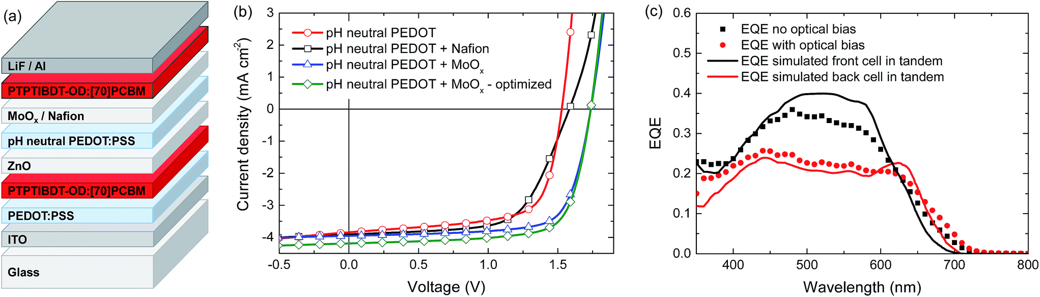 | ||
| Fig. 4 (a) Layout of the PTPTIBDT-OD:[70]PCBM homo-tandem polymer solar cell with Nafion or MoO3 layers in the intermediate contact. (b) Comparison of the J–V characteristics of PTPTIBDT-OD:[70]PCBM homo-tandem solar cells with and without Nafion or MoO3 layers in the intermediate contact. (c) EQE measurement of a PTPTIBDT-OD:[70]PCBM homo-tandem cell with and without optical bias (markers) in comparison with simulated EQEs of the subcells inside the tandem cell (solid lines). | ||
To further characterize the tandem solar cell, the external quantum efficiency (EQE) was measured. Because the solar cell consists of two identical absorber layers, the conventional tandem EQE measurement method described by Gilot et al.27 cannot be applied.28 Due to the interference effects in the layer stack, a different spectral response is expected for the front and the back cell inside the tandem.28 The data markers in Fig. 4c show two different responses recorded when the EQE of the homo-tandem cell was measured without (black squares) and with (red circles) bias light (at an intensity of 532 nm to give a Jsc equivalent to that for AM1.5 G white light), both measured at zero electrical bias for the tandem cell. The two measurements clearly show different spectral responses. To gain more insight into the origin of this difference, optical modelling using the transfer matrix formalism was performed on the homo-tandem device. The simulations use the wavelength dependent refractive index (n) and extinction coefficient (k) for all layers in the stack. The n and k values determined for the PTPTIBDT-OD:[70]PCBM blend are shown in the ESI.† The simulations provide the fraction of light absorbed by the front and back cells inside the tandem cell. The fraction of absorbed light at each wavelength was then corrected by the internal quantum efficiency (IQE) to obtain an estimate for the EQE of each of the two subcells (solid lines in Fig. 4c). The IQE used in the simulations was determined from the ratio of a single junction EQE and the fraction of absorbed photons, and was assumed to be the same for both subcells. When the experimental and simulated EQEs are compared, it is observed that the EQE measurement without optical bias resembles the expected response of the front cell, while the measurement with optical bias coincides fairly well with the predicted response of the back cell (Fig. 4c). The latter is expected, because the front cell absorption at 532 nm is significantly higher than the back cell absorption (solid black line in Fig. 4c), such that under 532 nm illumination the back cell is current limiting and will be the one that is measured in an EQE experiment (red circles in Fig. 4c). The AM1.5 G integrated current density estimated from the light biased-EQE measurement is 4.00 mA cm−2 and corresponds (in a first approximation) to the short-circuit current of the tandem cell. Consistently, the value corresponds to Jsc = 4.19 mA cm−2, measured in the J–V characteristics. Without light bias, one would expect the EQE to always reflect the current-limiting subcell, but this only holds when both subcells exhibit a negligible dark current. Using the highly conductive pH neutral PEDOT in the intermediate contact, this condition is not always met, and in such a case the unbiased EQE can represent the response of the cell with the lowest dark current as explained in detail by Colsmann et al.29 This is what is seen in the un-biased EQE experiment. The magnitude of the measured EQE is then lower than that of the actual EQE and consequently the actual current generation of the subcell cannot be estimated in this case.
The Voc of the optimized tandem cell reached up to 1.74 V. Surprisingly, the fill factors of the homo-tandem cells with MoO3 layers were high (0.73–0.75) likely as a consequence of the reduced light intensity in the subcells compared to the single junction. Thus, the Vmax of the optimized tandem cell was very high (1.48 V). In fact this Vmax enables water splitting to take place at the maximum power point of this solar cell.
Light-driven electrochemical water splitting
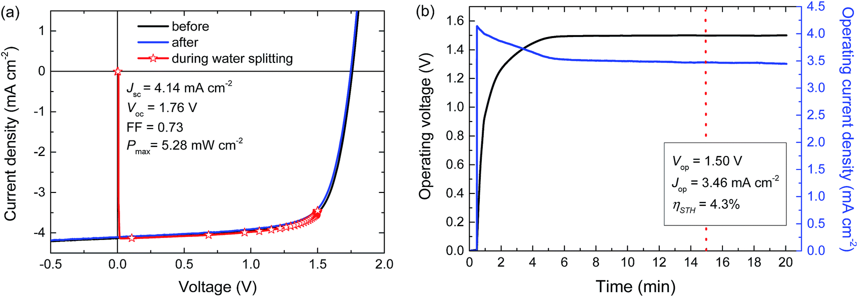
For a high solar-to-hydrogen energy conversion efficiency (ηSTH) in light-driven electrochemical water splitting, an optimized tandem solar cell (0.0676 cm2) was connected to two RuO2 catalytic electrodes on Ti substrates (∼1.2 cm2 catalyst) for oxygen and hydrogen evolution in 1.0 M KOH. The reasons for selecting RuO2 catalysts for both reactions are their low overpotentials, the ease of preparation and the good stability of the catalyst.6 The solar cell was illuminated with simulated AM1.5 G solar light for 20 min. The current density and voltage characteristics measured during a 20 min water splitting experiment are shown in Fig. 5. After 15 min of water splitting, the stabilized operating voltage (Vop) is 1.50 V, which is very close to the Vmax of the solar cell (1.48 V). Hence, the homo-tandem cell operates almost at its maximum power point, which is tailored to sunlight-driven electrochemical water splitting.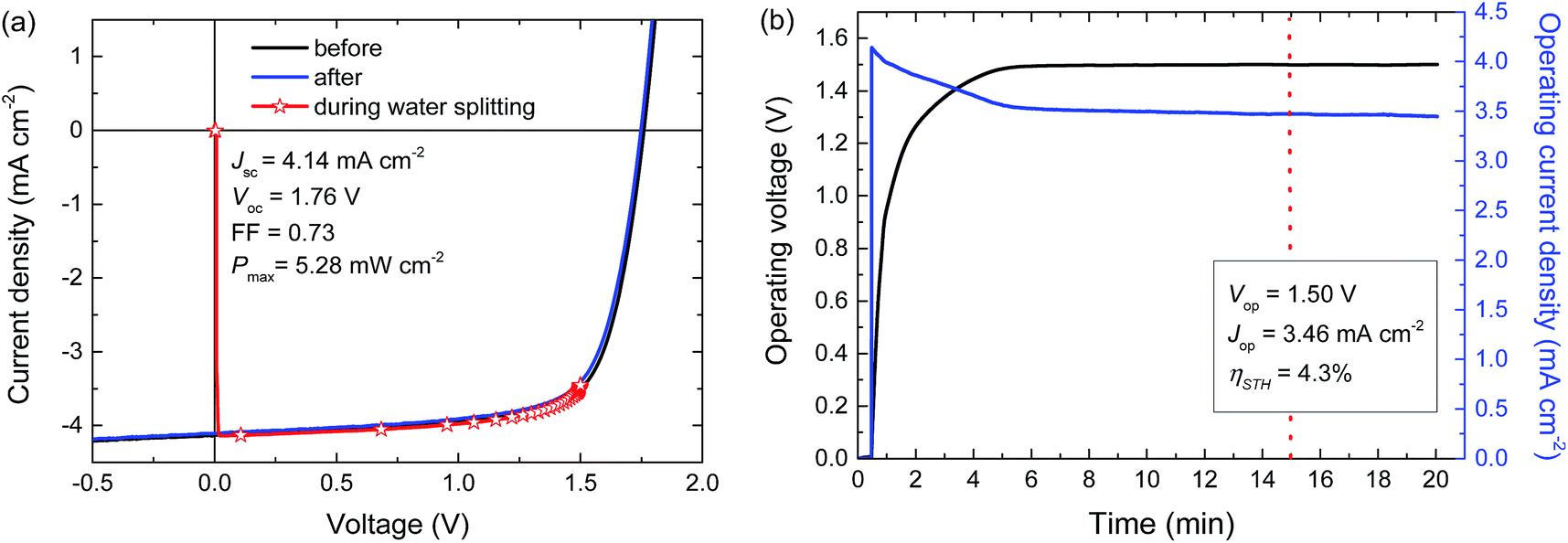 | ||
| Fig. 5 (a) J–V curves of the PTPTIBDT-OD:[70]PCBM homo-tandem cell before, during, and after the 20 min light-driven electrochemical water splitting experiment. (b) Simultaneous measurement of the operating voltage and current density of the device during light-driven electrochemical water splitting using RuO2 catalysts in 1.0 M KOH. The light source is not chopped and the electrolyte is not stirred during measurements. | ||
Fig. 5a shows the J–V characteristics of the solar cell just before, during and after the 20 min experiment. The J–V curves of the tandem cell before and after the water splitting experiment demonstrate the stability of the tandem cell during the test. The current under operation, Jop = 3.46 mA cm−2, shows a minimal decrease with time (Fig. 5b), reflecting the stability of the solar cell and the catalysts. Assuming 100% faradaic efficiency, the ηSTH = 1.23 × 3.46/100 = 4.3% after 15 min of operation (Table 2).
| OER | HER | V op [V] | J op [mA cm−2] | η STH [%] |
|---|---|---|---|---|
| RuO2 | RuO2 | 1.50 | 3.46 | 4.3 |
| RuO2 | Pt | 1.48 | 3.49 | 4.3 |
In the experiment we use a 0.0676 cm2 solar cell in combination with catalyst areas of 1.1 and 1.3 cm2. The relative areas of the solar cell and the catalyst are important for the overpotential. The Tafel plot in Fig. 6 shows the overpotentials for hydrogen and oxygen evolution for RuO2 catalysts as a function of the current density. At the current densities reached for the solar cell and the catalyst, the expected total overpotential is about 0.25 V, resulting in a total potential of 1.23 + 0.25 = 1.48 V, which is in very good agreement with the operating potential of 1.50 V (Fig. 5b). If the catalyst area would be reduced, the overpotential would increase and this would move the operating point away from the maximum power point of the solar cell. A reduction of the catalyst area by e.g. a factor of ten would increase the overpotential by 0.1 V and reduce ηSTH to 3.5%. Hence, balancing the nature and surface area of the catalysts with those of the materials used in the solar cell is crucial to achieve optimal performance.
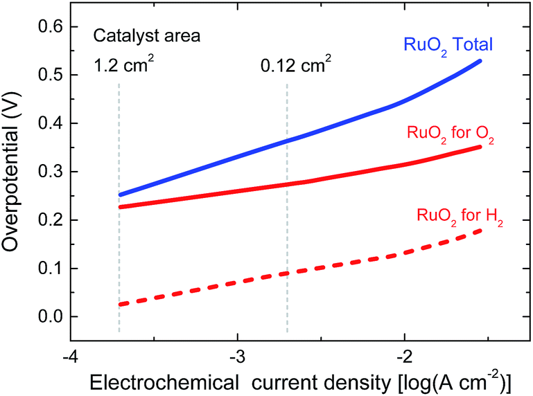 | ||
| Fig. 6 Tafel plots of RuO2 catalysts for hydrogen and oxygen evolution in 1.0 M KOH. The vertical lines indicate the current densities reached for the solar cell in Fig. 5b for two different catalyst areas during light-driven electrochemical water splitting. | ||
Next to RuO2 we also tested Pt as a catalyst for the hydrogen evolution reaction.3,7,8 For this purpose, the preceding experiment was repeated under identical conditions and with the same homo-tandem solar cell, only replacing the RuO2 catalyst for hydrogen evolution with a Pt plate (∼1.5 cm2). Fig. 7 shows the characterization of a 20 min water splitting experiment. The results are very similar to the previous experiment with two RuO2 catalysts. Replacing RuO2 with Pt for hydrogen evolution reduced the stabilized Vop to 1.48 V. The resulting Jop (3.49 mA cm−2) and ηSTH (1.23 × 3.49/100 = 4.3%) after 15 min of operation were very similar to those with RuO2 as the catalyst for hydrogen evolution. The stabilization of Vop and Jop in this case was faster. A reason can be that the charging of the double layer on Pt occurs faster than that on RuO2 for hydrogen evolution. The stability of the homo-tandem cell is evidenced in Fig. 6a.
 | ||
| Fig. 7 (a) J–V curves of the PTPTIBDT-OD:[70]PCBM homo-tandem cell before, during and after a 20 min light-driven electrochemical water splitting experiment. (b) Simultaneous measurement of the operating voltage and current density of the device during light-driven electrochemical water splitting using RuO2 and Pt catalysts in 1.0 M KOH. The light source is not chopped and the electrolyte is not stirred during measurements. | ||
For future and long term application the stability of the light-driven electrochemical water splitting stability is important. The 20 min experiments depicted in Fig. 5b and 7b indicate no fast degradation, but cannot be taken as evidence for stable operation. For stable light-driven water splitting the stability of the polymer solar cells and the catalysts is important. The stability of polymer solar cells has been discussed in several reviews30–32 and is determined by the stability of the active layer, the electrodes, and the interface layers which can be influenced by light, temperature, and the ingress of water and oxygen. The stability of RuO2 for oxygen and hydrogen evolution reactions in alkaline electrolytes has been described in detail,33 showing that dissolution of RuO2 during oxygen evolution is limiting the stability but that it is stable during hydrogen evolution. In the ESI† we demonstrate the stability of the RuO2 catalysts for 2 h, at current densities 20 times higher than in the water splitting experiments.
Conclusions
Light-driven electrochemical water splitting has been demonstrated using a new wide band gap semiconductor blend, PTPTIBDT-OD:[70]PCBM, in a homo-tandem cell configuration. To achieve a high enough voltage the homo-tandem cell uses an intermediate recombination contact layer that consists of a thin layer of MoO3 deposited on a conventional ZnO/pH neutral PEDOT:PSS junction to increase the work function at the hole extracting side of the stack.For light-driven electrochemical water splitting, the PTPTIBDT-OD:[70]PCBM homo-tandem cell was combined with a RuO2 catalyst for oxygen evolution and RuO2 or Pt catalysts for hydrogen evolution in 1.0 M KOH. The ηSTH is 4.3% and the device operated almost at the maximum power point of the solar cell due to its remarkably good fill factor (0.73). As a consequence, the difference between the PCE of the solar cell and the ηSTH of water splitting is solely due to overpotential losses. Further improvements in ηSTH will rely on improved polymer semiconductors to increase PCE and better electrocatalysts, rather than improving the design or optimization of the light-driven electrochemical water splitting device.
Experimental section
Materials
All commercial chemicals were used as received. Ruthenium(III) chloride (35–40% Ru) was obtained from Acros Organics. The platinum plate was obtained from Drijfhout. PTPTIBDT-OD was synthesized as described in the ESI.† [70]PCBM was obtained from Solenne BV. Water used in depositions and electrolytes was purified in a Millipore system and has a resistance of at least 18 MΩ.Electrochemical measurements
Cyclic voltammetry (CV) was conducted under an inert atmosphere using an Autolab PGSTAT30 with a three electrode setup equipped with an ITO working electrode covered with a spin coated polymer film, a silver counter electrode, and a silver electrode coated with silver chloride (Ag/AgCl) as the quasi reference electrode in combination with ferrocene/ferrocenium (Fc/Fc+) as the internal standard. A 1 M solution of tetrabutylammonium hexafluorophosphate (TBAPF6) in acetonitrile was used as the electrolyte. HOMO and LUMO levels were calculated from the oxidation and reduction potentials Eox/redvs. Fc/Fc+ using EHOMO/LUMO = −5.23 − qEox/red eV.The Tafel plot was constructed from the cyclic voltammetry (CV) measurements performed in the stationary current mode as described in detail in ref. 6.
RuO2 catalysts from thermal decomposition
Ti substrates (thickness 0.5 mm, 1.5 cm × 2 cm) were sonicated in acetone and then treated with air plasma in a Femto PCCE low pressure plasma system (Diener Electronic). A 270 W plasma was applied for 2 min. The RuO2 catalyst was prepared via thermal decomposition of RuCl3. For this purpose an aqueous RuCl3 solution (200 μL of a 0.2 M) was placed on a titanium substrate to form a catalyst area of about 1.3 cm2. The substrate was first dried at 90 °C on a hot plate for 20 min and then oxidized at 350 °C in air in an oven for 3 h.Device preparation
Photovoltaic devices were prepared first by spin casting a 40 nm thick PEDOT:PSS (Clevios® P VP AI 4083, H. C. Starck) onto pre-cleaned glass substrates with indium tin oxide (ITO) patterns (Naranjo Substrates). Prior to spin casting, PEDOT:PSS was filtered through an Acrodisc® LC25mm syringe filter with a 0.45 μm PVDF membrane. Then, the active layer was spin cast. Single junction devices were completed by thermally evaporating a back contact of 1 nm LiF and 100 nm Al at 3 × 10⁻⁷ mbar. For the tandem devices with a Nafion layer, the intermediate contact consisting of ZnO nanoparticles (∼30 nm), pH neutral PEDOT:PSS (∼15 nm), and Nafion (∼4 nm) was deposited sequentially by spin casting. For devices with the MoO3 layer, first ZnO nanoparticles (∼30 nm) and pH neutral PEDOT:PSS (∼15 nm) were spin cast. Afterwards, a 10 nm thick MoO3 film was deposited by thermal evaporation. For optimal performance, ZnO nanoparticles were deposited inside a glovebox with a nitrogen environment, while all other layers were spin cast in air. No heat treatment was applied to any of the layers. Layer thicknesses were measured with a Veeco Dektak 150 surface profiler.For PTPTIBDT-OD:[70]PCBM homo-tandems, both active layers were spin cast from a solution of PTPTIBDT-OD and [70]PCBM (1![[thin space (1/6-em)]](https://www.rsc.org/images/entities/char_2009.gif) :1.5 w/w) in chloroform containing 10 vol% o-DCB at 7 mg mL−1 polymer concentration. ZnO nanoparticles34,35 of ∼5 nm diameter were spin cast from a solution of 10 mg mL−1 ZnO in isopropanol (IPA). The pH neutral PEDOT:PSS was prepared by diluting Orgacon Neutral pH PEDOT:PSS from Agfa with ultra-pure water at a 1:1 volume ratio and adding 200 μL L−1 IPA. The solution was then filtered with a 5.0 μm Whatman Puradisc FP30 syringe filter. Nafion® (Aldrich chemistry, perfluorinated ion exchange resin 5 wt% in a mixture of lower aliphatic alcohols and H2O, containing 45% water) was first diluted in ethanol with a 1:200 volume ratio. The resulting solution was spin cast directly onto pH neutral PEDOT for an optimized thickness of 2–5 nm.
:1.5 w/w) in chloroform containing 10 vol% o-DCB at 7 mg mL−1 polymer concentration. ZnO nanoparticles34,35 of ∼5 nm diameter were spin cast from a solution of 10 mg mL−1 ZnO in isopropanol (IPA). The pH neutral PEDOT:PSS was prepared by diluting Orgacon Neutral pH PEDOT:PSS from Agfa with ultra-pure water at a 1:1 volume ratio and adding 200 μL L−1 IPA. The solution was then filtered with a 5.0 μm Whatman Puradisc FP30 syringe filter. Nafion® (Aldrich chemistry, perfluorinated ion exchange resin 5 wt% in a mixture of lower aliphatic alcohols and H2O, containing 45% water) was first diluted in ethanol with a 1:200 volume ratio. The resulting solution was spin cast directly onto pH neutral PEDOT for an optimized thickness of 2–5 nm.
Characterization
A Keithley 2400 source-measurement unit was used to measure current density to voltage (J–V) characteristics of the devices. The illumination was carried out with ∼100 mW cm−2 white light from a tungsten–halogen lamp filtered by a Schott GG385 UV filter and a Hoya LB120 daylight filter. No mismatch correction was performed. The measurements were performed inside a glovebox with a nitrogen atmosphere. The tandem devices were exposed to UV illumination (with a Spectroline EN-160L/F 365 nm lamp from Spectronics Corporation) for about 10 min to provide an ohmic contact between the ZnO and pH neutral PEDOT layers before being measured. To prevent parasitical charge collection due to the high lateral conductivity of pH neutral PEDOT, tandem and triple junction devices were measured with a mask that is slightly smaller than the device area, which is determined by the overlap of the ITO and Al electrodes. The actual device area was 0.09 cm2, while the corresponding mask size was 0.0676 cm2. For single junction devices, more accurate short circuit currents under AM1.5 G were calculated by convolution of the EQE measurements with the AM1.5 G solar spectrum.EQE measurements were performed in a homebuilt set-up. Mechanically modulated (SR 540, Stanford Research) monochromatic (Oriel Cornerstone 130) light from a 50 W tungsten halogen lamp (Osram 64610) was used as a probe light together with continuous bias light from a solid state laser (B&W Tek Inc., λ = 532 nm, 30 mW) through an aperture of 2 mm diameter. The intensity of the bias laser was adjusted using a variable neutral density filter. The response was recorded using a lock-in amplifier (Stanford Research Systems SR830), over a resistance of 50 Ω. For all the single junction devices, the measurement was carried out under a representative illumination intensity (AM1.5 G equivalent, provided by the 532 nm laser). A calibrated silicon solar cell was used as the reference. The devices were kept behind a quartz window in a nitrogen filled box during the measurements.
Solar to hydrogen conversion efficiencies were determined using a home-built setup. As the water splitting experiments took place in air, the solar cells were kept behind a quartz window in a nitrogen filled box and connected to the catalysts through external cables. The solar cell was illuminated with white-light from a tungsten–halogen lamp (∼100 mW cm−2) filtered by using a Schott GG385 UV filter and a Hoya HMC 80A 72 mm daylight filter. The solar cell was positioned by ensuring that the short-circuit current in this setup corresponds to AM1.5 G power standards. A Keithley 2600 source-measurement unit was used for the simultaneous measurement of current and voltage during water splitting.
Optical simulations
The optical modelling was done in SetFos version 3.2 (Fluxim AG, Switzerland). The optical constants for PTPTIBDT-OD:[70]PCBM were determined from reflection/transmission measurements on active layers on quartz.Acknowledgements
This project was carried out within the research programme of BioSolarCells, co-financed by the Dutch Ministry of Economic Affairs. This work is part of the research programme of the Foundation for Fundamental Research on Matter (FOM), which is part of the Netherlands Organization for Scientific Research (NWO). The research leading to these results has further received funding from the European Research Council under the European Union's Seventh Framework Programme (FP/2007-2013)/ERC Grant Agreement No. 339031 and the Mujulima project, Grant Agreement No. 604148. The research is part of the Solliance OPV programme and received funding from the Ministry of Education, Culture, and Science (NWO Gravity program 024.001.035).Notes and references
- M. Frites, W. B. Ingler Jr and S. U. M. Khan, J. Technol. Innovations Renewable Energy, 2014, 3, 6–11 CrossRef.
- S. Y. Reece, J. A. Hamel, K. Sung, T. D. Jarvi, A. J. Esswein, J. J. H. Pijpers and D. G. Nocera, Science, 2011, 334, 645–648 CrossRef CAS PubMed.
- G. H. Lin, M. Kapur, R. C. Kainthla and J. O. ' M. Bockris, Appl. Phys. Lett., 1989, 55, 386–387 CrossRef CAS.
- Y. Yamada, N. Matsuki, T. Ohmori, H. Mametsuka, M. Kondo, A. Matsuda and E. Suzuki, Int. J. Hydrogen Energy, 2003, 28, 1167–1169 CrossRef CAS.
- S. Esiner, H. van Eersel, M. M. Wienk and R. A. J. Janssen, Adv. Mater., 2013, 25, 2932–2936 CrossRef CAS PubMed.
- S. Esiner, R. E. M. Willems, A. Furlan, W. Li, M. M. Wienk and R. A. J. Janssen, J. Mater. Chem. A, 2015, 3, 23936–23945 CAS.
- O. Khaselev, A. Bansal and J. A. Turner, Int. J. Hydrogen Energy, 2001, 26, 127–132 CrossRef CAS.
- S. Licht, B. Wang, S. Mukerji, T. Soga, M. Umeno and H. Tributsch, Int. J. Hydrogen Energy, 2001, 26, 653–659 CrossRef CAS.
- D. J. D. Moet, P. de Bruyn, J. D. Kotlarski and P. W. M. Blom, Org. Electron., 2010, 11, 1821–1827 CrossRef CAS.
- C.-Y. Chang, L. Zuo, H.-L. Yip, C.-Z. Li, Y. Li, C.-S. Hsu, Y.-J. Cheng, H. Chen and A. K.-Y. Jen, Adv. Energy Mater., 2014, 4, 1301645 Search PubMed.
- L. Zuo, C.-C. Chueh, Y.-X. Xu, K.-S. Chen, Y. Zang, C.-Z. Li, H. Chen and A. K.-Y. Jen, Adv. Mater., 2014, 26, 6778–6784 CrossRef CAS PubMed.
- T. E. Kang, T. Kim, C. Wang, S. Yoo and B. J. Kim, Chem. Mater., 2015, 27, 2653–2658 CrossRef CAS.
- J. Yuan, Z. Zhai, H. Dong, J. Li, Z. Jiang, Y. Li and W. Ma, Adv. Funct. Mater., 2013, 23, 885–892 CrossRef CAS.
- Y. Liu, C.-C. Chen, Z. Hong, J. Gao, Y. M. Yang, H. Zhou, L. Dou, G. Li and Y. Yang, Sci. Rep., 2013, 3, 3356 Search PubMed.
- H. Zhou, Y. Zhang, C.-K. Mai, S. D. Collins, G. C. Bazan, T.-Q. Nguyen and A. J. Heeger, Adv. Mater., 2015, 27, 1767–1773 CrossRef CAS PubMed.
- J. You, C.-C. Chen, Z. Hong, K. Yoshimura, K. Ohya, R. Xu, S. Ye, J. Gao, G. Li and Y. Yang, Adv. Mater., 2013, 25, 3973–3978 CrossRef CAS PubMed.
- J. Cao, Q. Liao, X. Du, J. Chen, Z. Xiao, Q. Zuo and L. Ding, Energy Environ. Sci., 2013, 6, 3224–3228 CAS.
- Q. Liao, J. Cao, Z. Xiao, J. Liao and L. Ding, Phys. Chem. Chem. Phys., 2013, 15, 19990–19993 RSC.
- M. K. Poduval, P. M. Burrezo, J. Casado, J. T. Lopez Navarrete, R. P. Ortiz and T.-H. Kim, Macromolecules, 2013, 46, 9220–9230 CrossRef CAS.
- C. Zuo, J. Cao and L. Ding, Macromol. Rapid Commun., 2014, 35, 1362–1366 CrossRef CAS PubMed.
- J. Gilot, M. M. Wienk and R. A. J. Janssen, Appl. Phys. Lett., 2007, 90, 143512 CrossRef.
- D. J. D. Moet, P. de Bruyn and P. W. M. Blom, Appl. Phys. Lett., 2010, 96, 1535041 Search PubMed.
- Y. Sun, C. J. Takacs, S. R. Cowan, J. H. Seo, X. Gong, A. Roy and A. J. Heeger, Adv. Mater., 2011, 23, 2226–2230 CrossRef CAS PubMed.
- S. Kundu, S. R. Gollu, R. Sharma, S. Ga, A. Ashok, A. R. Kulkarni and D. Gupta, Org. Electron., 2013, 14, 3083–3088 CrossRef CAS.
- A. K. K. Kyaw, D. H. Wang, V. Gupta, J. Zhang, S. Chand, G. C. Bazan and A. J. Heeger, Adv. Mater., 2013, 25, 2397–2402 CrossRef CAS PubMed.
- J. Gilot, M. M. Wienk and R. A. J. Janssen, Adv. Mater., 2010, 22, E67–E71 CrossRef CAS PubMed.
- J. Gilot, M. M. Wienk and R. A. J. Janssen, Adv. Funct. Mater., 2010, 20, 3904–3911 CrossRef CAS.
- R. Timmereck, K. Leo and M. Riede, Prog. Photovoltaics, 2015, 23, 1353–1356 Search PubMed.
- D. Bahro, M. Koppitz, A. Mertens, K. Glaser, J. Mescher and A. Colsmann, Adv. Energy Mater., 2015, 5, 1501019 Search PubMed.
- N. Grossiord, J. M. Kroon, R. Andriessen and P. W. M. Blom, Org. Electron., 2012, 13, 432–456 CrossRef CAS.
- J. U. Lee, J. W. Jung, J. W. Jo and W. H. Jo, J. Mater. Chem., 2012, 22, 24265–24283 RSC.
- M. Jørgensen, K. Norrman, S. A. Gevorgyan, T. Tromholt, B. Andreasen and F. C. Krebs, Adv. Mater., 2012, 24, 580–612 CrossRef PubMed.
- S. Cherevko, S. Geiger, O. Kasian, N. Kulyk, J.-P. Grote, A. Savan, B. R. Shrestha, S. Merzlikin, B. Breitbach, A. Ludwig and K. J. J. Mayrhofer, Catal. Today, 2016, 262, 170–180 CrossRef CAS.
- C. Pacholski, A. Kornowski and H. Weller, Angew. Chem., Int. Ed., 2002, 41, 1188–1191 CrossRef CAS.
- W. J. E. Beek, M. M. Wienk, M. Kemerink, X. Yang and R. A. J. Janssen, J. Phys. Chem. B, 2005, 109, 9505–9516 CrossRef CAS PubMed.
Footnote |
| † Electronic supplementary information (ESI) available: Synthetic procedures. See DOI: 10.1039/c5ta10459a |
| This journal is © The Royal Society of Chemistry 2016 |