
 Open Access Article
 This Open Access Article is licensed under a
 Creative Commons Attribution 3.0 Unported Licence
Cross-linked single-walled carbon nanotube aerogel electrodes via reductive coupling chemistry†
Martina
De Marco
a,
Foivos
Markoulidis
a,
Robert
Menzel
bc,
Salem M.
Bawaked
d,
Mohamed
Mokhtar
d,
Shaeel A.
Al-Thabaiti
d,
Sulaiman N.
Basahel
d and
Milo S. P.
Shaffer
*a
aDepartment of Chemistry, Imperial College London, UK. E-mail: m.shaffer@imperial.ac.uk
bSchool of Chemistry, University of Leeds, LS2 9JT, UK
cBio Nano Consulting, The Gridiron Building, One Pancras Square, London, N1C 4AG, UK
dDepartment of Chemistry, Faculty of Science, King Abdulaziz University, Jeddah, Saudi Arabia
First published on 3rd March 2016
Abstract
Single-walled carbon nanotube (SWCNT) anions can be cross-linked by a dielectrophile to form covalent, carbon-bonded organogels. Freeze-drying produces cryogels with low density (2.3 mg cm−3), high surface area (766 m2 g−1), and high conductivity (9.4 S m−1), showing promise as supercapacitor electrodes. Counterion concentration controls debundling, grafting ratio, as well as all the resulting properties.
In the past decade, single-walled carbon nanotubes (SWCNTs) have been assembled into three-dimensional architectures, in order to combine their intriguing properties (mechanical,1,2 thermal3 and electrical,4 very high aspect ratio and high surface area5) with the unique features of porous networks.6 To this end, SWCNTs have been trapped within other gel-forming systems such as polymers,7–9 DNA,10 surfactants,11 silica12 and resorcinol–formaldehyde.13 To avoid the contaminating, often insulating, secondary gel-former, SWCNTs have been cross-linked using a range of strategies, including cycloaddition reactions,14 Sonogashira coupling,15 linking of pre-introduced carboxyl16 or hydroxyl17 functionalities with bi- (or tri)-functional reagents, and even dry via electron beam irradiation.18 However, existing methods tend to degrade the SWCNTs aspect ratio, damage the carbon framework and debundle inefficiently. A network derived from individualised, covalently interconnected, high aspect ratio SWCNTs is the ideal target for maximising surface area and accessible porosity, while retaining high conductivity, important for applications including catalysis, energy storage, controlled release systems and other multifunctional devices.19–21
Overcoming the intrinsic, strong, van der Waals interactions (∼40kBT nm−1) that drive SWCNT bundle formation is challenging.22 Ultrasonication is damaging, hard to scale and yields only low concentrations of individualised SWCNTs.23 Covalent modification can limit bundling,24–26 though many routes also introduce damage,27 or only functionalise exposed bundle surfaces. In contrast, chemical reduction is a promising functionalisation strategy that can generate true solutions of individualised, negatively-charged SWCNT ions (nanotubides)28–30 at high concentrations, avoiding the damage caused by sonication or aggressive oxidation.31 Nanotubides can react with an extensive variety of functional groups including alkyl/aryl halides,32,33 peroxides,34 disulfides,35 epoxides36etc.; however, cross-linking reactions via this route have not yet been explored. The present study uses difunctional reagents to cross-link nanotubide solutions to form fully carbon-bonded covalent organogels.
Liquid ammonia,37 THF38 and DME39 are the most common solvents employed for reductive chemistry; however N,N-dimethylacetamide (DMAc) has recently been shown to be particularly suitable for a convenient, one-pot reaction,40 using Na/naphthalene as a charge transfer agent. p-Diiodobenzene (p-DIB) was selected as a soluble, rigid, potentially conjugated, dielectrophilic cross-linking agent, using the established iodide reactivity (Fig. 1). A relatively high nominal SWCNT concentration (0.15 M) was selected to increase chances of network formation, whilst remaining within the range found to be effective for simple nanotubide grafting reactions.40,41
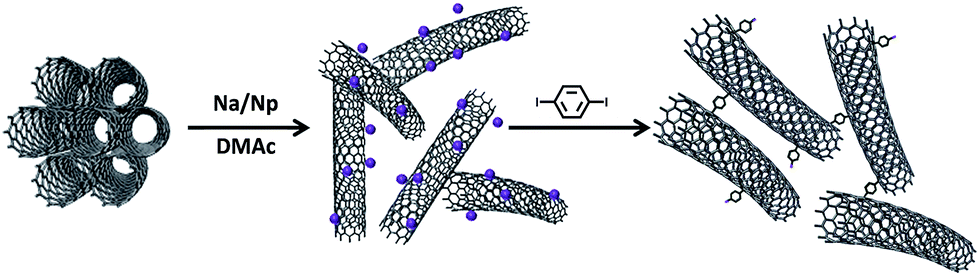 | ||
| Fig. 1 Representation of the reaction sequence. | ||
Since the sodium concentration ([Na]) and/or degree of charge is known to control the level of solubilisation and functionalisation, a range of [Na] was tested, adding one equivalent of p-DIB (to Na) for the cross-linking, in order to identify the optimum conditions. At higher [Na], the immediate gelation of the network, following the addition of p-DIB, indicated successful cross-linking of the SWCNTs, through the double covalent attachment of phenyl groups. In contrast, using mono-substituted iodobenzene (IB) as the electrophile (SWCNT-IB control) led only to a liquid solution of functionalised CNTs (photograph S1c†).
During thermo-gravimetric analysis, under nitrogen, the grafted species decompose and desorb from the surface, as identified by mass spectroscopy (TGA-MS, Fig. 2a and S1†). A SWCNT control, treated in the same reaction conditions but without adding p-DIB (treated SWCNTs), has a very similar TGA trace to the pristine SWCNTs, indicating that the charging process has little effect on the CNT structure. A control adding p-DIB to the quenched nanotubides showed a very similar TGA to the treated SWCNTs, excluding a contribution from physisorption. The grafting ratio (GR), the weight ratio of the grafted species to the nanotube framework, was determined from the TGA data. GR and tendency to gel is correlated with [Na], and the corresponding C![[thin space (1/6-em)]](https://www.rsc.org/images/entities/char_2009.gif) :Na ratio (Fig. 2b). Although TGA shows that all the samples are functionalised, the samples at low sodium concentration ([Na] < 9 mM; (C:Na > 20)) did not gel. Selecting the correct [Na] (and hence C:Na ratio) is crucial to maximise the availability of negative charges on the nanotube surface and to prevent ‘salting out’ due to cation condensation on the nanotubide surface.42 Recent work has shown that [Na] is the critical parameter determining the level of functionalisation across all carbon concentrations.40,41 In the present study, the optimum is observed for an absolute metal concentration of 15 mM, providing a GR of 17 wt%.
:Na ratio (Fig. 2b). Although TGA shows that all the samples are functionalised, the samples at low sodium concentration ([Na] < 9 mM; (C:Na > 20)) did not gel. Selecting the correct [Na] (and hence C:Na ratio) is crucial to maximise the availability of negative charges on the nanotube surface and to prevent ‘salting out’ due to cation condensation on the nanotubide surface.42 Recent work has shown that [Na] is the critical parameter determining the level of functionalisation across all carbon concentrations.40,41 In the present study, the optimum is observed for an absolute metal concentration of 15 mM, providing a GR of 17 wt%.
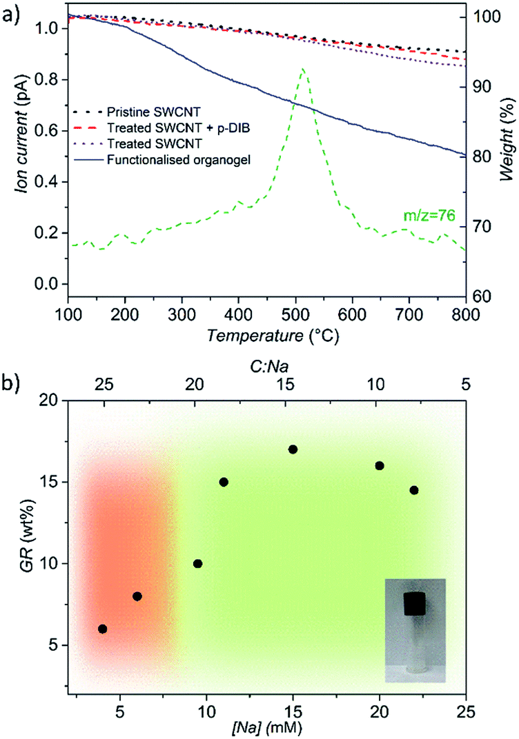 | ||
| Fig. 2 (a) TGA of pristine SWCNTs (dotted line) and control samples (dashed lines). TGA-MS of representative functionalised organogel (10 wt%, solid line) shows a weight loss related to the presence of the functional groups (m/z 76, C6H4+), (b) grafting ratios (wt%) versus [Na]. Green area indicates the zone of gel formation. | ||
Raman spectroscopy confirmed that covalent modification has occurred, without introducing excessive damage due to side reactions (Fig. S2†). The intensity ratio (ID/IG) of the D band (1293 cm−1) over the tangential mode G band (1590 cm−1) is commonly taken as an indication of the introduction of sp3 (or other) defects. The ID/IG ratio is consistently slightly raised (0.16–0.20) after the cross-linking reaction, compared to the treated (0.06) and pristine (0.05) SWCNTs, and is maximised at [Na] ∼ 15 mM, following the trend in GR.
Following oxygen quenching, the SWCNT DMAc-organogels were converted to hydrogels by a careful sequence of solvent exchanges (DMAc–THF–water, Fig. S3†) then freeze-dried, in order to preserve the 3D network structure from capillary collapse during solvent evaporation. The resulting highly porous (99.8%, Table S6†), low density (2–3 mg cm−3) cryogels exhibited minimal shrinkage (<∼1%) and retained defined, cylindrical shapes (Fig. S3b†), suggesting a network robustness derived from successful chemical cross-linking of the SWCNTs. Scanning Electron Microscopy (SEM) showed a hierarchical interconnected, ordered porous honeycomb structure, with straight and micrometer-sized parallel channels, formed during freezing, and walls of networked SWNTs (Fig. 3a and b). Transmission Electron Microscopy (TEM) images (Fig. 3c) confirmed successful network formation between small bundles and individual nanotubes, with much lower degree of bundling than the starting material (Fig. S5†).
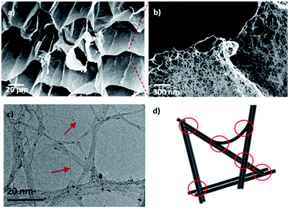 | ||
| Fig. 3 Dried cryogel (17 wt%) (a and b) SEM images at different magnifications, (c) TEM and (d) corresponding schematic, red arrows indicating individual nanotubes, red circles indicating the junction points. Black particles are residual Fe catalyst. | ||
XPS analysis identified residual iodine in the samples (Fig. S4†); however, direct iodination of the nanotube sidewalls is unlikely considering the absence of iodine in the XPS of the SWCNT-IB control. In the single electron transfer mechanism proposed for nanotubide grafting,35 the higher reactivity of benzene radicals should dominate the reaction. The iodine content (at%) in the cross-linked samples follows the general trend in grafting ratio (Fig. 4a), and can be related to the fraction of grafted phenyl groups that are cross-linked rather than monofunctionalised (‘CL:mono’, Fig. 4b & S4†). Di-reacted p-DIB at junctions (Fig. 3d) creates porosity by cross-linking the SWCNTs in a defined network, and all the associated iodine is subsequently washed out as NaI. However, in other locations, as the network forms, the SWCNTs are far from contact, and the rigid p-DIB can only react once, leaving phenyl iodide grafted to the sidewalls. The quantity of and distance between the junctions is presumably determined by extent of debundling, concentration and geometric constraints (related to the length of the CNTs and small size of p-DIB molecule). At higher [Na], where more salting out of bundles is expected, a higher proportion of cross-links are formed (greater CL:mono), most likely between parallel SWCNTs; randomly arranged, individualised SWCNTs offer a smaller fraction of sites for crosslinking. Interestingly, the degree of cross-linking correlates closely with the average pore size (nm) of the cryogels, calculated using Barrett, Joyner and Halenda analysis of the nitrogen adsorption data. Increased pore size can be attributed to a coarser network of more bundled/salted out SWNTs, which is also reflected in the pore size distribution (Fig. S7†).
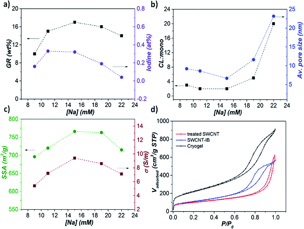 | ||
| Fig. 4 (a) Plot of GR (wt%) and iodine (at%) versus [Na], (b) estimated ratio of cross-linked/mono reacted phenyl groups (CL:mono, refer to Fig. S4† for the calculation) and average pore size (nm, Fig. S7†) versus [Na], (c) specific surface area (SSA, m2 g−1) and electrical conductivity (S m−1) versus [Na], (d) N2 adsorption/desorption isotherm of cryogel (17 wt%), SWCNT-IB and treated SWCNT. | ||
Nitrogen adsorption/desorption isotherms of the cryogels (Fig. 4d) are type IV, indicative of a mesoporous material. Consistent with a hierarchical structure, micropores are also present, evidenced by the steep isotherm profile at low relative pressure. Specific surface areas (SSAs) calculated according to the Brunauer–Emmett–Teller (BET) equation, range between 695 and 766 m2 g−1 (Table S6†), more than three times the SSA of the treated SWCNT control (217 m2 g−1) and double the SWCNT-IB control (366 m2 g−1), reflecting the effectiveness of cross-linking in preventing rebundling. The highest surface area is achieved for the sample charged with [Na] 15 mM (17 wt%), further confirming the importance of the sodium concentration in effective dissolution.
Interestingly, the volumetric electrical conductivity through the monolith is high (9.4 S m−1 at 10% of compression, Table S6†), given the low density, reflecting the intimate SWCNT cross-links. Smaller diameter bundles in networks have been reported to have improved electrical contacts, and therefore higher conductivity,43,44 consistent with the trend observed in Fig. 4c. It is important to note that all the trends in Fig. 4a–c, grafting ratio, degree of cross-linking, surface area, and electrical conductivity, as well as ID/IG, are closely correlated, and consistent with a maximised degree of individualisation in the network at an optimum [Na] of 15 mM.
As a preliminary illustration of the opportunities for electrochemical applications, a full working supercapacitor cell was assembled employing cryogel derived from [Na] = 15 mM as the active electrodes. The monolithic aerogels were combined with whisker-based current collectors to form a complete, symmetric, binderless electric double layer capacitor (EDLC), with 1 cm2 active electrode area (SI), and low charge transfer resistance (ESI, Fig. S9†). The specific electrode capacitance, calculated from cyclic voltammetry at 1 V s−1, was 55 F g−1 (Fig. S8a†), which is similar to recently reported values for denser aerogels incorporated in EDLC devices.45 One of the attractive features of such devices is their excellent cycling stability; indeed, after 105 cycles of galvanostatic charge–discharge (GCD), the nanotubide-derived electrode retained 88% of the initial capacitance and a Coulombic efficiency of 95% (Fig. 5), in agreement with similar energy storage devices,46 and confirming a robust and inherently porous structure.
 | ||
| Fig. 5 (a) Ragone plot of GCD-derived power and energy densities (per kg of active material), (b) plot of capacitance retention (%) and Coulombic efficiency (%) over 105 cycles of charge discharge at 50 mA. | ||
Moreover, due to the open porous network, the GCD curves display a symmetrical shape at high applied current, highlighting the high rate stability of the cryogel for EDLC applications (Fig. S8b†). Promising results were also obtained for GCD-derived energy density (Ed) and power density (Pd) (Fig. S8c†), showing good stability over long term cycling even in the absence of binders; the present device has comparable performance to current other CNT-based supercapacitors (Fig. S8d†). The results are a proof of concept that the directly networked SWCNTs can form fully functioning, binderless supercapacitors. Overall performance could be improved, for example by using different electrolytes (e.g. low-viscosity ionic liquids or aqueous systems), or tuning the electrode geometry. The use of supercritical rather than freeze-drying may enhance accessible area further, and offers routes to improve volumetric performance as energy storage electrodes.
Conclusions
The present work reports a successful new method of producing SWCNTs cryogels by cross-linking reduced salts with p-DIB and subsequent freeze-drying. This approach is particularly attractive compared to previous cross-linking strategies, as the SWCNTs can be individualised without shortening or other framework damage. The cross-linking reaction is intrinsically enabled by the charge-based dissolution mechanism, and leads to a direct carbon–carbon bonded network throughout the gel, maximising robustness and electrochemical stability. The unreacted iodide component may provide a useful site for further modification. The behaviour of the system expands and is consistent with developing understanding of nanotubide polyelectrolytes. A sodium concentration of 15 mM is found to maximise the debundling and the grafting ratio, leading to material with enhanced surface area (766 m2 g−1) and an abundant pore distribution at lower pore sizes (10–22 nm) estimated from BET (N2) measurements. These characteristics, in combination with good electrical conductivity (9.4 S m−1), low mass density (2.3 mg cm−3) and chemical stability, make the cryogels promising candidates for a variety of electrochemical energy-conversion technologies, as well as environmental applications such as sorption, separation and filtration. Preliminary electrochemical tests of EDLCs assembled with the current cryogel electrodes show good performance and stability over long cycles (105) of charge–discharge. The use of the same strategy with more concentrated, cleaner, more exfoliated and higher aspect ratio nanotubide solutions, different types and degrees of cross-linkers, and different drying protocols will allow the morphology of the aerogels to be optimised for different applications.Acknowledgements
The authors would like to thank Edward White for TEM images and Adam Clancy for discussion during the experiments. Financial support for this project was provided by the Deanship of Scientific Research at King Abdulaziz University (Grant D-1-434), and EPSRC grant EP/L001896/1.Notes and references
- J. P. Salvetat, J. M. Bonard, N. H. Thomson, A. J. Kulik, L. Forró, W. Benoit and L. Zuppiroli, Appl. Phys. A, 1999, 69, 255–260 CrossRef CAS.
- J.-P. Salvetat, G. A. D. Briggs, J.-M. Bonard, R. R. Bacsa, A. J. Kulik, T. Stöckli, N. A. Burnham and L. Forró, Phys. Rev. Lett., 1999, 82, 944–947 CrossRef CAS.
- J. Hone, M. Whitney, C. Piskoti and A. Zettl, Phys. Rev. B: Condens. Matter Mater. Phys., 1999, 59, R2514–R2516 CrossRef CAS.
- A. Javey, J. Guo, Q. Wang, M. Lundstrom and H. Dai, Nature, 2003, 424, 654–657 CrossRef CAS PubMed.
- A. Peigney, C. Laurent, E. Flahaut, R. R. Bacsa and A. Rousset, Carbon, 2001, 39, 507–514 CrossRef CAS.
- S. Nardecchia, D. Carriazo, M. L. Ferrer, M. C. Gutierrez and F. del Monte, Chem. Soc. Rev., 2013, 42, 794–830 RSC.
- Y. Li, D. Yang, A. Adronov, Y. Gao, X. Luo and H. Li, Macromolecules, 2012, 45, 4698–4706 CrossRef CAS.
- A. Koganemaru, Y. Bin, Y. Agari and M. Matsuo, Adv. Funct. Mater., 2004, 14, 842–850 CrossRef.
- J. Zou, J. Liu, A. S. Karakoti, A. Kumar, D. Joung, Q. Li, S. I. Khondaker, S. Seal and L. Zhai, ACS Nano, 2010, 4, 7293–7302 CrossRef CAS PubMed.
- G. N. Ostojic, ChemPhysChem, 2012, 13, 2102–2107 CrossRef CAS PubMed.
- M. B. Bryning, D. E. Milkie, M. F. Islam, L. A. Hough, J. M. Kikkawa and A. G. Yodh, Adv. Mater., 2007, 19, 661–664 CrossRef CAS.
- J. G. Duque, C. E. Hamilton, G. Gupta, S. A. Crooker, J. J. Crochet, A. Mohite, H. Htoon, K. A. D. Obrey, A. M. Dattelbaum and S. K. Doorn, ACS Nano, 2011, 5, 6686–6694 CrossRef CAS PubMed.
- M. A. Worsley, J. H. Satcher and T. F. Baumann, Langmuir, 2008, 24, 9763–9766 CrossRef CAS PubMed.
- M. Holzinger, J. Steinmetz, D. Samaille, M. Glerup, M. Paillet, P. Bernier, L. Ley and R. Graupner, Carbon, 2004, 42, 941–947 CrossRef CAS.
- R. Kumar and C. N. R. Rao, J. Mater. Chem. A, 2015, 3, 6747–6750 CAS.
- A. Satti, A. Perret, J. E. McCarthy and Y. K. Gun'ko, J. Mater. Chem., 2010, 20, 7941–7943 RSC.
- M. B. Jakubinek, B. Ashrafi, J. Guan, M. B. Johnson, M. A. White and B. Simard, RSC Adv., 2014, 4, 57564–57573 RSC.
- S. G. Miller, T. S. Williams, J. S. Baker, F. Solá, M. Lebron-Colon, L. S. McCorkle, N. G. Wilmoth, J. Gaier, M. Chen and M. A. Meador, ACS Appl. Mater. Interfaces, 2014, 6, 6120–6126 CAS.
- K. H. An, W. S. Kim, Y. S. Park, J. M. Moon, D. J. Bae, S. C. Lim, Y. S. Lee and Y. H. Lee, Adv. Funct. Mater., 2001, 11, 387–392 CrossRef CAS.
- E. Frackowiak and F. Béguin, Carbon, 2001, 39, 937–950 CrossRef CAS.
- L. Li, Z. Wu, S. Yuan and X.-B. Zhang, Energy Environ. Sci., 2014, 7, 2101–2122 CAS.
- L. Girifalco, M. Hodak and R. Lee, Phys. Rev. B: Condens. Matter Mater. Phys., 2000, 62, 13104–13110 CrossRef CAS.
- H. C. Yau, M. K. Bayazit, J. H. G. Steinke and M. S. P. Shaffer, Chem. Commun., 2015, 51, 16621–16624 RSC.
- J. E. Riggs, Z. Guo, D. L. Carroll and Y.-P. Sun, J. Am. Chem. Soc., 2000, 122, 5879–5880 CrossRef CAS.
- R. Bandyopadhyaya, E. Nativ-Roth, O. Regev and R. Yerushalmi-Rozen, Nano Lett., 2002, 2, 25–28 CrossRef CAS.
- C. A. Dyke and J. M. Tour, J. Phys. Chem. A, 2004, 108, 11151–11159 CrossRef CAS.
- J. Zhang, H. Zou, Q. Qing, Y. Yang, Q. Li, Z. Liu, X. Guo and Z. Du, J. Phys. Chem. B, 2003, 107, 3712–3718 CrossRef CAS.
- F. Liang, A. K. Sadana, A. Peera, J. Chattopadhyay, Z. Gu, R. H. Hauge and W. E. Billups, Nano Lett., 2004, 4, 1257–1260 CrossRef CAS.
- S. Fogden, C. A. Howard, R. K. Heenan, N. T. Skipper and M. S. P. Shaffer, ACS Nano, 2011, 6, 54–62 CrossRef PubMed.
- D. Wunderlich, F. Hauke and A. Hirsch, J. Mater. Chem., 2008, 18, 1493–1497 RSC.
- H. Yoon, M. Yamashita, S. Ata, D. N. Futaba, T. Yamada and K. Hata, Sci. Rep., 2014, 4, 3907 Search PubMed.
- B. Gebhardt, Z. Syrgiannis, C. Backes, R. Graupner, F. Hauke and A. Hirsch, J. Am. Chem. Soc., 2011, 133, 7985–7995 CrossRef CAS PubMed.
- J. Chattopadhyay, A. K. Sadana, F. Liang, J. M. Beach, Y. Xiao, R. H. Hauge and W. E. Billups, Org. Lett., 2005, 7, 4067–4069 CrossRef CAS PubMed.
- P. S. Engel, W. E. Billups, D. W. Abmayr, K. Tsvaygboym and R. Wang, J. Phys. Chem. C, 2008, 112, 695–700 CAS.
- J. Chattopadhyay, S. Chakraborty, A. Mukherjee, R. Wang, P. S. Engel and W. E. Billups, J. Phys. Chem. C, 2007, 111, 17928–17932 CAS.
- Y. Martinez-Rubi, B. Ashrafi, J. Guan, C. Kingston, A. Johnston, B. Simard, V. Mirjalili, P. Hubert, L. Deng and R. J. Young, ACS Appl. Mater. Interfaces, 2011, 3, 2309–2317 CAS.
- K. F. Kelly and W. E. Billups, Acc. Chem. Res., 2013, 46, 4–13 CrossRef CAS PubMed.
- D. Voiry, C. Vallés, O. Roubeau and A. Pénicaud, Carbon, 2011, 49, 170–175 CrossRef CAS.
- J. M. Englert, C. Dotzer, G. Yang, M. Schmid, C. Papp, J. M. Gottfried, H.-P. Steinrück, E. Spiecker, F. Hauke and A. Hirsch, Nat. Chem., 2011, 3, 279–286 CrossRef CAS PubMed.
- A. J. Clancy, J. Melbourne and M. S. P. Shaffer, J. Mater. Chem. A, 2015, 3, 16708–16715 CAS.
- T. Morishita, A. J. Clancy and M. S. P. Shaffer, J. Mater. Chem. A, 2014, 2, 15022–15028 CAS.
- G. S. Manning, J. Chem. Phys., 1969, 51, 924–933 CrossRef CAS.
- P. E. Lyons, S. De, F. Blighe, V. Nicolosi, L. F. C. Pereira, M. S. Ferreira and J. N. Coleman, J. Appl. Phys., 2008, 104, 044302 CrossRef.
- D. Hecht, L. Hu and G. Grüner, Appl. Phys. Lett., 2006, 89, 133112 CrossRef.
- E. Wilson and M. F. Islam, ACS Appl. Mater. Interfaces, 2015, 7, 5612–5618 CAS.
- P.-C. Chen, G. Shen, Y. Shi, H. Chen and C. Zhou, ACS Nano, 2010, 4, 4403–4411 CrossRef CAS PubMed.
Footnote |
| † Electronic supplementary information (ESI) available. See DOI: 10.1039/c5ta10311h |
| This journal is © The Royal Society of Chemistry 2016 |