‘Donor-free’ oligo(3-hexylthiophene) dyes for efficient dye-sensitized solar cells†
Received
11th November 2015
, Accepted 14th December 2015
First published on 16th December 2015
Abstract
The common trend in designing dyes for use in DSSCs with iodide-based electrolyte is based on a donor–π spacer–acceptor (D–π–A) architecture. Here, we report two ‘donor-free’ cyanoacrylic end-functionalized oligo(3-hexylthiophene) dyes (5T and 6T). Despite having no donor group, both dyes show reversible first oxidation process. Both 5T and 6T have n-hexyl alkyl chains to retard aggregation at different positions as well as different numbers of thiophene moieties. However, the dyes showed similar absorption properties and redox potentials. The DSSCs based on these dyes give power conversion efficiencies of more than 7%, although a significant difference in the VOC and FF has been observed. Using electrochemical impedance spectroscopy, this is attributed to the presence of more trap states when 6T attaches to TiO2 and modifies the surface, mainly affecting the fill factor. Overall, these dyes introduce a new and effective design concept for liquid-electrolyte DSSC sensitisers.
Introduction
Over the last 20 years, dye-sensitised solar cells (DSSCs) have attracted significant interest as low-cost alternatives to conventional photovoltaic technologies. They present a record efficiency (uncertified) of ∼13% under standard reporting conditions.1,2 Ruthenium complexes have been designed to work as sensitisers with standard I−/I3− liquid redox electrolyte, giving a record certified efficiency of 11.9 ± 0.4%.3,4 However, several challenges limit their development for large scale applications including material costs, difficulty in purification and environmental impact. In solid-state dye-sensitised solar cells (ssDSSC) where the liquid based I−/I3− redox couple is exchanged for a hole conductor, thinner TiO2 films are needed because of mass transport limitations or insufficient pore filling.5–7 Accordingly, metal-free organic sensitisers with high extinction coefficients have been developed and the overwhelming trend in designing these dyes is based on a donor–π spacer–acceptor (D–π–A) architecture.8,9 In such dyes, the donor and the π spacer part contain the HOMO of the dye while the LUMO is distributed on the acceptor part and the anchoring group. Upon excitation, the electrons move from donor to acceptor through the π-bridge. This modular design allows organic dyes to show great diversity and flexibility. Cyanoacrylic acid is a commonly used acceptor which decreases the energy gap between HOMO and LUMO, thus leading to a red shift of the lowest energy absorption maximum.10 Various donor groups have been investigated, including anthraquinone, boradiazaindacene, carbazole, coumarin, N,N-dialkylaniline, hemicyanine, heteroanthracene, indoline, merocyanine, tetrahydroquinoline, triarylamine, squaraine, perylene and polymeric species.11 The electron-donor group is usually bulky in order to reduce the electron recombination between redox electrolyte and the TiO2 surface and to stabilize the oxidized dye. The influence of the donor size in D–π–A dye was studied by Yang et al.9 A higher voltage was observed and reported when a bulky-indoline moiety was introduced as donor into the IQ4 dye.12
However, previous study in our group on ssDSSCs using a ‘donor-free’ sensitiser, cyanoacrylic end-functionalized oligo(3-hexylthiophene) (5T) and ‘donor–π–acceptor’ sensitiser based on the same structure (MK-2) showed that without an electron donor group, a significantly-higher open-circuit voltage (VOC) could be achieved while the short-circuit current (JSC) remained approximately the same. This resulted in a significantly higher over-all efficiency, comparable with the very best dyes for ssDSSCs. Devices using 5T as the sensitiser and spiro-OMeTAD as the hole-transport material gave an efficiency of 4.4% whereas the ones using MK-2 as the sensitiser gave only 2.8%.13
To follow up the above work, in the present study we have tested 5T in liquid-state dye-sensitised solar cells using classic I−/I3− redox couple. Another donor-free dye, 6T, which has one more thiophene unit than 5T, as well as a simpler synthetic scheme is also designed, synthesised, characterised and tested. To compare the performance of 5T and 6T with the traditional D–π–A dyes, we also fabricated the liquid-state dye-sensitised solar cells based on MK2 dye and using I−/I3− redox couple. The dyes studied in the present work have similar molecular backbone as MK2 – both use cyanoacrylic acid as an acceptor group and four thiophene derivatives as a π-spacer. While MK2 has a terminal carbazole donor group to complete the D–π–A structure, 5T and 6T have additional thiophene(s) to elongate the π-system to achieve a molecular size similar to MK2. The best PCE obtained with MK2, 5T, 6T and N719 are respectively, 5.05%, 7.64%, 7.07% and 8.89% (under the conditions optimized for N719). Most of the D–π–A dyes exhibiting good efficiencies in liquid-state dye-sensitised solar cells have complicated structures and have low synthetic yield.11 However, the donor-free dyes reported in the present study can be easily synthesised using cross-coupling and have high synthetic yield, opening a new strategy of designing highly efficient ‘donor-free’ dyes in the future. DSSCs using 6T showed significantly higher VOC but lower JSC and FF than those using 5T. By using electrochemical impedance spectroscopy (EIS), it was found that 6T leads to more trapping states, which may be attributed to the extra conjugation or different position of alkyl chain of 6T than 5T.
Results and discussion
Synthesis
The synthesis of oligo(3-hexylthiophene)s and poly(3-hexylthiophene) has been reported using several routes and the challenge is to separate the high-purity monodisperse regioregular oligo(3-hexylthiophene)s in reasonable quantities. The previous work in our group was based on extending the oligomer stepwise by one unit per cross-coupling followed by activation of the newly formed chain end to give 5T.14 This approach was part of a study to prepare shorter oligomers including 1–5 thiophene units,14 however it is not very efficient when the longer chains of 5T and 6T are specifically desired. In this work, 6T was therefore synthesised using a ‘Fibonacci Route’ reported by Heeney.15 The regioregularity of 6T is proven by the presence (brominated precursor) and absence (stannylated precursor) of 3-bond H–H coupling of the terminal protons in NMR. Also, 6T has a sharp melting point of 132 °C. The synthetic route is shown in Scheme 1. The synthesis of the oligomer (3HT)n was achieved by the coupling of Br–(3HT)n−x and (3HT)x–SnBu3. Thus, (3HT)n with n = 1, 2, 3, 5, 8, 13 and 21 can be obtained more efficiently than adding one thiophene unit per cross-coupling. Also, this strategy allowed easy purification by vacuum distillation of solvent and column chromatography. Finally, in this work, a thiophene unit functionalized with a cyanoacrylic end group was added to enable appropriate attachment to the TiO2. We note that this Fibonacci route leads to alkyl chains in a different position. The alkyl chains for 5T are at the 3-positions of the thiophene, however, for 6T, they are at the 2-positions. Alkyl chains were attached to the thiophene unit to avoid strong π–π interaction,16 which has been proven to lead to a decreased electron injection in the solar cells.17 Furthermore, alkyl chains play a role in reducing charge recombination between electrons in TiO2 and the redox electrolyte.18
 |
| | Scheme 1 The structure of 5T and 6T (above) and the synthetic procedure for the synthesis of 6T. | |
Optical properties
Optical properties of 5T and 6T were studied in dichloromethane at 2 × 10⁻⁶ M. For both dyes, the lowest energy absorption band is around 480 nm. The absorption band positions and their extinction coefficients are summarized in Table 1. The addition of thiophene unit and extension of π-system does not lead to significant changes in either the position of the lowest energy absorption band or the extinction coefficient of this band but has a stronger influence on the higher energy band, which corresponds to a π–π* transition of the thiophene backbone and is more intense for 6T (Fig. 1). This assignment was confirmed by measuring UV-vis spectra in different solvents [see the ESI Fig. S2(a)†]. In a mixture of acetonitrile and butanol, the lowest energy absorption band of both compounds blue shifted significantly while the higher energy band remained at the same wavelength, indicating the charge transfer nature of the lowest energy absorption band. Fig. 1 also gives the absorption spectra of 5T and 6T on 3 μm transparent TiO2 films. Both spectra broadened, implying the dyes form Herring-bone aggregates on TiO2 films.196T showed wider absorption than 5T on TiO2 film because of its extra conjugation. This has also been seen by Masumoto, et al.,20 who studied the optical properties of thiophene-based oligomers and found the effective conjugation length of oligothiophenes was six thiophene rings.
Table 1 Photophysical and electrochemical properties of 5T and 6T
|
|
λ
max
/nm (ε × 10−4/M−1 cm−1) |
E
ox
vs. NHE/V |
E
red
vs. NHE/V |
E
0–0
/eV |
ΔEelectrochemical/V |
E*dvs. NHE/V |
|
Absorption and emission spectra were measured in DCM with a concentration of 2 × 10⁻⁶ M at room temperature.
Potential was measured in DCM with 0.3 M [TBA][PF6] as electrolyte and calibrated with ferrocene/ferrocenium (Fc/Fc+) as an internal reference and converted to NHE by addition of 0.63 V.
0–0 transition energy, E0–0 estimated from the intercept of the normalized absorption and emission spectra in DCM.
Estimated excited state redox potential, estimated by subtracting E0–0 from the ground state oxidation potential.
|
|
5T
|
478 (3.9), 376 (2.4) |
1.08 |
−1.29 |
2.15 |
2.37 |
−1.07 |
|
6T
|
486 (3.9), 401 (3.1) |
0.98 |
−1.32 |
2.30 |
2.30 |
−1.32 |
 |
| | Fig. 1 UV-vis spectra of 5T and 6T at 2 × 10⁻⁶ M in DCM (a) and 3 μm transparent on TiO2 (b). | |
Photoluminescence was also studied in solution [see the ESI Fig. S2(b)†]. 5T and 6T both showed very broad emission response, covering the visible and even near-IR region. 5T showed a bigger Stokes-shift than 6T (5973 cm−1 and 2908 cm−1, respectively).
Electrochemical properties and DFT calculations
Electrochemical properties for 5T and 6T were investigated by cyclic voltammetry (CV) and square-wave voltammetry (SWV). Despite the fact that 5T and 6T don't have donor groups, both the dyes showed a reversible first oxidation process (ESI, Fig. S3 and S4†). The values against NHE are presented in Table 1. The addition of one more thiophene unit in 6T shifts the oxidation peak to less positive potential; 5T shows the first oxidation potential at 1.08 V whereas 6T shows it at 0.98 V (see ESI Tables S1–S3†). They are both higher than that of the iodide/triiodide (0.40 V vs. NHE) redox electrolyte energy level, guaranteeing good driving force for the dye regeneration. Little difference was observed for the reduction processes (5T: −1.29 V, 6T: −1.32 V vs. NHE). This is because the LUMO is localized mainly at the cyanoacrylic moiety and is little affected by the length of the thiophene chain. The electrochemical results were supported by DFT calculations. The energy level schemes for the Kohn–Sham orbitals of 5T and 6T, including selected Kohn–Sham orbitals and the HOMO–LUMO energy gap are shown in Fig. 2. For both 5T and 6T, the HOMO is distributed along the conjugated π-system and the LUMO is located on the cyanoacetic acid unit through the thiophene, allowing good charge separation and charge directionality after photo-excitation and preventing back regeneration of the dye with the injected electrons.21 Time-dependent DFT calculation was performed with a dichloromethane polarisable continuum model (PCM)22 using the CAM-B3LYP functional.23 The result is consistent with the experimental UV/vis and is shown in ESI Tables S1 and S2.†
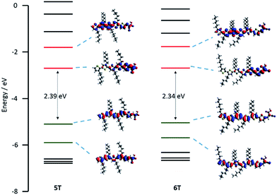 |
| | Fig. 2 Energy level schemes for the Kohn–Sham orbitals of 5T and 6T, including selected Kohn–Sham orbitals and the HOMO–LUMO energy gap. | |
Photovoltaic performance of DSSCs
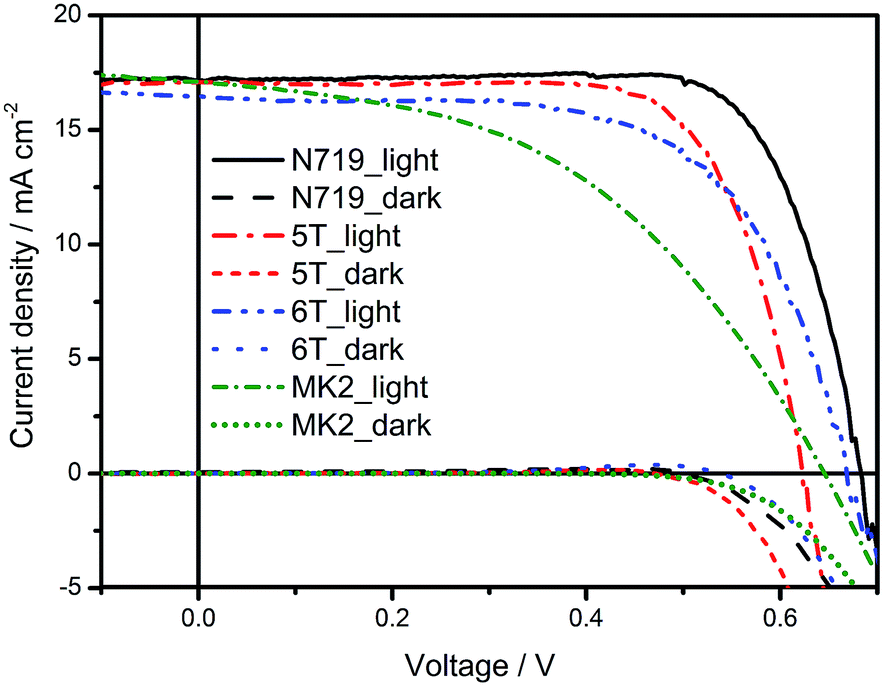
The photovoltaic performance of the DSSCs based on iodide/triiodide redox electrolyte using the 5T and 6T dyes was analysed as a function of dye soaking time of 3–24 hours and compared with DSSCs using N719 (ESI Fig. S4–S6†). The best performance for all the dyes was observed for the devices soaked for 24 hours. To compare the performance of 5T and 6T with the traditional D–π–A dyes, DSSCs based on MK2 dye were also fabricated. The J–V characteristics of the best cells are shown in Fig. 3 and the corresponding device characteristics along with the estimated amount of dye loaded on 18 μm TiO2 photoelectrodes soaked in the corresponding dyes for 24 hours are given in Table 2. N719 has the highest JSC because it exhibits the widest absorption spectrum. The IPCE of DSSCs using 5T and 6T (see ESI Fig. S8†) exceeded 60% over most of visible light region from 400 nm to 650 nm, with a maximum of ∼80% at around 500 nm and the lowest values were between 650 and 700 nm. N719 showed better performance in this region. The slight shift in the absorption onset of the 6T as compared to 5T on TiO2 [Fig. 1(b)] is also evident from the shift in the IPCE (Fig. S8†) and results in a higher VOC for 6T compared to 5T (Table 2). The absorbed amount of dye increased slightly with increasing the number of thiophene. This can be understood in terms of increased π–π interaction with expanding π-conjugation. 6T would form a thicker aggregate on TiO2 surface due to increased number of thiophene and since the adsorbed dye amount of the former is larger than the 5T it would in turn result in slower diffusion of redox species in the mesoporous TiO2 leading to increased charge transport resistance (as observed in the EIS measurements discussed later) leading to lower FF. A higher dye loading of the 6T compared to 5T on TiO2 (Table 2), however, doesn't lead to a higher short circuit photocurrent as might be expected. Hagberg et al. observed similar trends in a series of organic chromophores when the π-conjugation between the donor (triphenylamine moiety) and the acceptor (cyanoacetic acid moiety) were systematically extended.24 A similar trend was also observed by Barea et al. in n-thiophene absorbers when increasing the conjugation length from 2 to 6.21 Such a decrease in JSC was attributed to the differences in dye binding and orientation affecting injection efficiency.21,24 Overall, the best PCE efficiencies obtained were N719 (8.94%), 5T (7.64%) and 6T (7.07%). 5T has a lower PCE than N719 mainly due to a loss in VOC, which is not unusual in organic dyes. A significant decrease in the fill factor is observed when comparing the devices using 6T and others. In contrast, the best PCE efficiency obtained in DSSCs based on MK2 (processed under conditions optimised for N719) is 5.05%, with JSC of 17.64 mA cm−2, VOC of 0.64 V and FF of 45.0%. The best PCE value reported in literature for MK2 sensitised DSSCs is 8.3% with JSC of 15.22 mA cm−2, VOC of 0.73 V and FF of 75.0%.25 The higher JSC and lower FF observed in the present study could be related to the photoelectrode thickness of 18 μm in contrast to the 16 μm reported in literature. Whereas the lower VOC is related to the electrolyte composition, especially the iodine concentration of 0.2 M in the former in contrast to 0.03 M used in the present study.
 |
| | Fig. 3
J–V characteristics and IPCEs of the DSSCs using N719, 5T and 6T under dark and under AM1.5 simulated sunlight of illumination of 100 mW cm−2. | |
Table 2 Photovoltaic performance for the champion cells measured under AM 1.5 illumination. The photoelectrodes were soaked in the dye solution for 24 hours
| Dye |
J
SC/mA cm−2 |
V
OC/V |
FF/% |
Efficiency/% |
Dye loading/×107 mol cm−2 |
|
N719
|
17.48 |
0.68 |
74.7 |
8.89 |
3.04 |
|
5T
|
17.15 |
0.62 |
72.0 |
7.64 |
5.09 |
|
6T
|
16.85 |
0.67 |
62.8 |
7.07 |
5.38 |
Electrochemical impedance spectroscopy (EIS)
In order to understand the reasons behind the observed photovoltaic performance as a function of thiophene chain length, detailed impedance spectroscopy measurements were performed on the best cells under illumination from a LED at different bias potentials in the frequencies between 1 MHz and 0.1 Hz. The data were fitted using the transmission line model.26,27 The equivalent circuit is shown in Fig. S9.† From the fittings, charge transfer resistance (RCT), electron transport resistance (Rtrans) and chemical capacitance of TiO2 (CChem) were extracted. The electron lifetime and electron transport time were calculated according to the equations: τe = RCT × CChem and τtrans = Rtrans × CChem, respectively. Fig. 4 shows the charge transfer resistance and the chemical capacitance of the TiO2 as a function of voltage and the electron lifetime as a function of capacitance. Although it is increasingly common to use the chemical capacitance as a reference for the relative position of the conduction band edge in different devices, Barnes, et al.28 have highlighted the need to analyse both charge and transport data in addition to simple electron lifetime measurements when drawing conclusions about DSSC behaviour, for the reason that some dyes may modify the distribution of trap states as well as shifting the semiconductor conduction band. Based on this knowledge, we first examine the relationship between transport time and capacitance. The longer transport time of 6T over 5T indicates more trap states in the presence of 6T (Fig. 4(a)) also consistent with the higher capacitance for 6T (Fig. 4(b)). A low FF is generally ascribed to high series resistance,29,30 which includes the redox reaction resistance at the counter electrode, the resistance of electron transport by ions in the electrolyte and electron transport through the TiO2. The longer transport time for 6T indicates a higher resistance for transport, which leads to a lower FF and a slightly lower JSC for 6T than the other dyes. This may be caused by the extra conjugation of 6T compared to 5T, or the different position of the alkyl chains which modifies the TiO2 surface differently. The longer electron lifetime for 6T over 5T [Fig. 4(c)], despite the higher number of traps, corresponds with the experimental VOC which is higher for 6T. In contrast, 5T and N719 have similar trap states, so any different device behaviour can be attributed to a shift of conduction band edge, possibly related to the different protonation state of N719 compared with 5T and 6T. From Fig. 4(c)N719 has much longer electron lifetime than 5T and this leads to a final VOC value trend of N719 > 6T > 5T.
 |
| | Fig. 4 (a) Transport time plotted against capacitance of the TiO2. (b) Charge transfer resistance and chemical capacitance of the TiO2 plotted against the voltage. (c) Electron lifetime plotted against capacitance of the TiO2. | |
Conclusions
Two ‘donor-free’ cyanoacrylic end-functionalized oligo(3-hexylthiophene) dyes (5T and 6T) have been synthesised, and this dye design used for the first time as effective sensitizers for liquid-state dye-sensitized solar cells with I−/I3− redox couple, giving power conversion efficiency of 7.64% and 7.07%, respectively. 6T showed a significantly higher VOC than 5T but lower JSC and FF. By using electrochemical impedance spectroscopy (EIS), it was found that 6T has more trap states, attributed to the extra conjugation or different position of alkyl chain of 6T. These dyes can be easily synthesised using cross-coupling and showed reversible first oxidation processes even without donor groups. Overall, this opens up a new strategy for future dye design with the potential for simpler dyes and also new insights into optimised sensitizer design and performance.
Experimental
Synthetic procedure
Materials.
All reagents were purchased from either Sigma-Aldrich or Alfa-Aesar and were used as received without further purification. Tributyl(3,4′,4′′,4′′′,4′′′′-pentahexyl[2,2′:5′,2′′:5′′,2′′′:5′′′,2′′′′-quinquethiophen]-5-yl)-stannane was synthesised according to literature15 and the detailed experimental method is in the ESI.†
Synthesis of 4′,4′′,4′′′,4′′′′,4′′′′′-pentahexyl-[2,2′:5′,2′′:5′′,2′′′:5′′′,2′′′′:5′′′′,2′′′′′-sexithiophen]-5-carbaldehyde.
Tributyl(3,4′,4′′,4′′′,4′′′′-pentahexyl[2,2′:5′,2′′:5′′,2′′′:5′′′,2′′′′-quinquethiophen]-5-yl)-stannane (800 mg, 0.71 mmol) and 5-bromo-2-thiophenecarboxaldehyde (100 mg, 0.52 mmol) were dissolved in anhydrous toluene (10 ml) and bubbled with N2 for 30 min. Tetrakis(triphenylphosphine) palladium (Pd(PPh3)4) (40 mg, 0.035 mmol) was added and the solution was bubbled with N2 for another 10 min before the solution was heated to 90 °C for 72 h. The organic solvents were removed by vacuum, then the crude product was purified by column chromatography (SiO2, hexane) to give a red oil (290 mg, 59% yield). 1H NMR (500 MHz, CDCl3): 9.48 (s, 1H), 7.31 (s, 1H), 7.10 (s, 1H), 7.07 (s, 1H), 6.99 (m, 1H), 6.98 (s, 1H), 6.82 (d, J = 4.0 Hz, 1H), 6.77 (d, J = 4.0 Hz, 1H), 6.60 (m, 1H), 2.87–2.68 (m, 8H), 2.4 (t, J = 7.7 Hz, 2H), 1.73–1.62 (m, 10H), 1.28–1.15 (m, 30H), 0.91–0.84 (m, 15H).
Synthesis of 2-cyano-3-[4′,4′′,4′′′,4′′′′,4′′′′′-pentahexyl[2,2′:5′,2′′:5′′,2′′′:5′′′,2′′′′:5′′′′,2′′′′′-sexithiophen]-5-yl]acrylic acid (6T).
4′,4′′,4′′′,4′′′′,4′′′′′-pentahexyl-[2,2′:5′,2′′:5′′,2′′′:5′′′,2′′′′:5′′′′,2′′′′′-sexithiophen]-5-carbaldehyde (290 mg, 0.31 mmol) and cyanoacetic acid (40 mg, 0.46 mmol) were dried under vacuum. Then ethanol (2.5 ml) was added and the solution was bubbled with N2 for 10 min. Piperidine (132 mg, 1.55 mmol) was added and the reaction was heated up to 75 °C for 6 h. Then, the mixture was poured into 100 ml of aqueous HCl 1 M and extracted with diethyl ether. The crude was purified by size exclusion column chromatography (Biobeads S-X3, DCM) to give a red solid (210 mg, 67% yield). 1H NMR (500 MHz, CDCl3): 8.32 (s, 1H), 7.70 (d, J = 4.2 Hz, 1H), 7.29 (s, 1H), 7.25 (d, J = 4.0 Hz, 1H), 7.04 (s, 1H), 7.01–6.99 (m, 2H), 6.98 (s, 1H), 6.93 (s, 1H), 2.84–2.76 (m, 8H), 2.64 (t, 7.7 Hz, 2H), 1.75–1.64 (m, 10H), 1.48–1.32 (m, 30H), 0.96–0.90 (m, 15H). MS ESI (m/z): [M]+ calcd 1009.41500. Found: 1009.41166. Anal. calc. for C58H75NO2S6: C 68.93, H 7.48, N 1.39. Found: C 69.01, H 7.55, N 1.37%. Melting point: 132 °C.
Methods
Chemical characterisation.
1H NMR spectra were recorded on Bruker Advance 500 spectrometer. The deuterated solvents are indicated; chemical shifts, δ, are given in ppm, referenced to TMS, standardized by the solvent residual signal (1H). Coupling constants (J) are given in hertz (Hz). MS were recorded on ThermoElectron MAT 900 using electrospray ionization (ESI) technique. Elemental analyses were carried out by Stephen Boyer at London Metropolitan University using a Carlo Erba CE1108 Elemental Analyser.
Electrochemical characterisation.
All cyclic voltammetry and square wave voltammetry measurements were carried out in anhydrous CH2Cl2 using 0.3 M [TBA][PF6] electrolyte in a three-electrode system. The solution was purged with N2 prior to measurement. The working electrode was a Pt disk. The reference electrode was Ag/AgCl and the counter electrode was a Pt rod. All measurements were made at room temperature using an μAUTOLAB Type III potentiostat, driven by the electrochemical software GPES. Cyclic voltammetry (CV) measurements used scan rates of 0.1, 0.2, 0.4, 0.6, 0.8 and 1 V s−1. Square wave voltammetry (SWV) experiments were carried out at a step potential of 4 mV, a square wave amplitude of 25 mV and a square wave frequency of 15 Hz, giving a scan rate of 40 mV s−1. Ferrocene was used as internal standard in each measurement and potentials are quoted versus NHE against which ferrocene/ferrocenium was observed at 0.63 V.
Optical characterisation.
Solution UV-visible absorption spectra were recorded using Jasco V-670 UV/vis/NIR spectrophotometer controlled using the SpectraManager software. Photoluminescence (PL) spectra were recorded with Fluoromax-3 fluorimeter controlled by the ISAMain software. All samples were measured in a 1 cm cell at room temp. with dichloromethane as a solvent. Concentration of 2 × 10⁻⁶ M were used for UV/visible and PL.
Computational details.
The molecular structures were optimised in vacuum, using the software Avogadro31 to enter the starting geometry. Then the structure was optimised in dichloromethane, using the optimised structure from vacuum. All calculations were carried out using the Gaussian 09 program32 with the hybrid B3LYP functional23 and the standard 6-31G(d) basis set. Time-dependent DFT calculations (TD-DFT) were performed using Gaussian 09 program with a dichloromethane polarisable continuum model (PCM)22 using CAM-B3LYP functional. The 20 lowest singlet electronic transitions were calculated and processed with the GaussSum software package.33
Solar cell fabrication.
To make the working electrodes, fluorine doped tin oxide (FTO) coated glass was washed using 2% Hellmanex solution and then by sonication in distilled water, acetone and methanol. The glasses were further cleaned by UV-ozone cleaner for 20 min. The cleaned glass was pre-treated with a solution of TiCl4 (40 mM in water) at 80 °C for 30 min, rinsed with water and ethanol and sintered at 450 °C for 30 min. The working electrodes were screen printed using commercial TiO2 paste (DSL 18NR-T, Dyesol) as the transparent layer and (DSL 18NR-AO, Dyesol) as the scattering layer. The total thickness of the TiO2 layer was maintained at 18 μm and the area of the layer was 0.28 cm2. The films were dried at 125 °C for 6 min and gradually heated over an hour to 510 °C and annealed for 10 min using a programmable hotplate. The films were allowed to cool to room temperature and post-treated with TiCl4 (40 mM in water) at 80 °C for 30 min and sintered at 500 °C for 30 min. When the temperature dropped to about 80–100 °C, the working electrodes were put into 0.5 mM dye solution in acetonitrile![[thin space (1/6-em)]](https://www.rsc.org/images/entities/char_2009.gif) :t-butanol (1:1) and soaked for different time durations (3–24 hours). The electrodes were removed and washed with the same solvent mixture, to remove any unbound dye molecules. Counter electrodes were prepared by drilling a hole into pre-cut FTO glass. The FTO glass pieces were washed with distilled water, 0.1 M HCl in ethanol and finally acetone. The electrodes were heated at 400 °C for 15 min both before and after a layer of Platisol (Solaronix) was applied. The solar cells were then assembled in the sandwich mode where the two electrodes were stuck together using thermoplastic (Surlyn). The electrolyte used was a mixture of 1-butyl-3-methylimidazolium iodide (1.3307 g, 1 M), I2 (0.0381 g, 0.03 M), LiI (0.067 g, 0.1 M), 4-tert butylpyridine (0.3380 g, 0.5 M), guanidine thiocyanate (0.059 g, 0.1 M) in acetonitrile (4.25 ml) and valeronitrile (0.75 ml). To compare the performance of 5T and 6T with the traditional D–π–A dyes, we also fabricated the DSSCs based on MK2 dye and using the same redox couple mentioned above. The electrolyte was introduced by vacuum suction into the hole and the hole was sealed by cover glass. The J–V measurements were carried out using a computer-controlled digital source meter (Keithley 2400) under simulated AM1.5G irradiation from a solar simulator (92250 A, Newport, USA) under 1 sun equivalent (100 W m−2) condition. A light mask was used on the DSSCs, so the illuminated active area of DSSC was fixed to 0.126 cm2. Incident photon-to-current conversion efficiency (IPCE) measurements were carried out with a Bentham PVE300 photovoltaic spectral response system controlled by BenWin+ software, light intensity was measured by a calibrated silicon photodiode (300–1100 nm).
:t-butanol (1:1) and soaked for different time durations (3–24 hours). The electrodes were removed and washed with the same solvent mixture, to remove any unbound dye molecules. Counter electrodes were prepared by drilling a hole into pre-cut FTO glass. The FTO glass pieces were washed with distilled water, 0.1 M HCl in ethanol and finally acetone. The electrodes were heated at 400 °C for 15 min both before and after a layer of Platisol (Solaronix) was applied. The solar cells were then assembled in the sandwich mode where the two electrodes were stuck together using thermoplastic (Surlyn). The electrolyte used was a mixture of 1-butyl-3-methylimidazolium iodide (1.3307 g, 1 M), I2 (0.0381 g, 0.03 M), LiI (0.067 g, 0.1 M), 4-tert butylpyridine (0.3380 g, 0.5 M), guanidine thiocyanate (0.059 g, 0.1 M) in acetonitrile (4.25 ml) and valeronitrile (0.75 ml). To compare the performance of 5T and 6T with the traditional D–π–A dyes, we also fabricated the DSSCs based on MK2 dye and using the same redox couple mentioned above. The electrolyte was introduced by vacuum suction into the hole and the hole was sealed by cover glass. The J–V measurements were carried out using a computer-controlled digital source meter (Keithley 2400) under simulated AM1.5G irradiation from a solar simulator (92250 A, Newport, USA) under 1 sun equivalent (100 W m−2) condition. A light mask was used on the DSSCs, so the illuminated active area of DSSC was fixed to 0.126 cm2. Incident photon-to-current conversion efficiency (IPCE) measurements were carried out with a Bentham PVE300 photovoltaic spectral response system controlled by BenWin+ software, light intensity was measured by a calibrated silicon photodiode (300–1100 nm).
Electrochemical impedance spectroscopy (EIS).
Electrochemical impedance spectroscopy (EIS) was performed using the AUTOLAB PGSTAT30 potentiostat controlled by FRA software, version 4.9.007. The cells were measured in a frequency range between 7 MHz and 0.02 Hz with forward bias potentials controlled by the intensity of LED lights. The resulting impedance spectra were analysed with Z-view software (Scribner Associate Inc) version 3.3a on the basis of the two channel transmission line model.
Acknowledgements
We thank China Scholarship Council, the University of Edinburgh and the EPSRC Apex project (EP/M023532/1) for financial support. Open data: http://dx.doi.org/10.7488/ds/279. C. L. B. and A. O. B. thank Regione Lombardia and Fondazione Cariplo for financial support and the use of instrumentation purchased through the “SmartMatLab Centre” project.
Notes and references
- A. Yella, H. W. Lee, H. N. Tsao, C. Y. Yi, A. K. Chandiran, M. K. Nazeeruddin, E. W. G. Diau, C. Y. Yeh, S. M. Zakeeruddin and M. Gratzel, Science, 2011, 334, 629 CrossRef CAS PubMed.
- S. Mathew, A. Yella, P. Gao, R. Humphry-Baker, B. F. E. Curchod, N. Ashari-Astani, I. Tavernelli, U. Rothlisberger, M. K. Nazeeruddin and M. Gratzel, Nat. Chem., 2014, 6, 242 CrossRef CAS PubMed.
- M. A. Green, K. Emery, Y. Hishikawa, W. Warta and E. D. Dunlop, Prog. Photovoltaics, 2015, 23, 1 Search PubMed.
-
R. Komiya, A. Fukui, N. Murofushi, N. Koide, R. Yamanaka and H. Katayama, presented in part at the Technical Digest, 21st International Photovoltaic Science and Engineering Conference, Fukuoka, 2011 Search PubMed.
- J. Garcia-Canadas, F. Fabregat-Santiago, H. J. Bolink, E. Palomares, G. Garcia-Belmonte and J. Bisquert, Synth. Met., 2006, 156, 944 CrossRef CAS.
- K. Tennakone, G. R. Kumara and A. R. Kumarasinghe, Semicond. Sci. Technol., 1995, 10, 1689 CrossRef.
- F. Fabregat-Santiago, J. Bisquert, L. Cevey, P. Chen, M. K. Wang, S. M. Zakeeruddin and M. Gratzel, J. Am. Chem. Soc., 2009, 131, 558 CrossRef CAS PubMed.
- E. Gabrielsson, H. Ellis, S. Feldt, H. N. Tian, G. Boschloo, A. Hagfeldt and L. C. Sun, Adv. Energy Mater., 2013, 3, 1647 CrossRef CAS.
- J. B. Yang, P. Ganesan, J. Teuscher, T. Moehl, Y. J. Kim, C. Y. Yi, P. Comte, K. Pei, T. W. Holcombe, M. K. Nazeeruddin, J. L. Hua, S. M. Zakeeruddin, H. Tian and M. Gratzel, J. Am. Chem. Soc., 2014, 136, 5722 CrossRef CAS PubMed.
- Z. S. Wang, Y. Cui, K. Hara, Y. Dan-Oh, C. Kasada and A. Shinpo, Adv. Mater., 2007, 19, 1138 CrossRef CAS.
- A. Hagfeldt, G. Boschloo, L. C. Sun, L. Kloo and H. Pettersson, Chem. Rev., 2010, 110, 6595 CrossRef CAS PubMed.
- K. Pei, Y. Z. Wu, A. Islam, Q. Zhang, L. Y. Han, H. Tian and W. H. Zhu, ACS Appl. Mater. Interfaces, 2013, 5, 4986 CAS.
- A. Abate, M. Planells, D. J. Hollman, S. D. Stranks, A. Petrozza, A. R. S. Kandada, Y. Vaynzof, S. K. Pathak, N. Robertson and H. J. Snaith, Adv. Energy Mater., 2014, 4, 1400166 Search PubMed.
- M. Planells, A. Abate, H. J. Snaith and N. Robertson, ACS Appl. Mater. Interfaces, 2014, 6, 17226 CAS.
- F. P. V. Koch, P. Smith and M. Heeney, J. Am. Chem. Soc., 2013, 135, 13695 CrossRef CAS PubMed.
- M. K. Nazeeruddin, P. Pechy, T. Renouard, S. M. Zakeeruddin, R. Humphry-Baker, P. Comte, P. Liska, L. Cevey, E. Costa, V. Shklover, L. Spiccia, G. B. Deacon, C. A. Bignozzi and M. Gratzel, J. Am. Chem. Soc., 2001, 123, 1613 CrossRef CAS PubMed.
- N. Koumura, Z. S. Wang, S. Mori, M. Miyashita, E. Suzuki and K. Hara, J. Am. Chem. Soc., 2006, 128, 14256 CrossRef CAS PubMed.
- L. Schmidt-Mende, J. E. Kroeze, J. R. Durrant, M. K. Nazeeruddin and M. Gratzel, Nano Lett., 2005, 5, 1315 CrossRef CAS PubMed.
- M. Guo, P. Diao, Y. H. Ren, F. S. Meng, H. Tian and S. M. Cai, Sol. Energy Mater. Sol. Cells, 2005, 88, 23 CrossRef CAS.
- Y. Kanemitsu, K. Suzuki, Y. Masumoto, Y. Tomiuchi, Y. Shiraishi and M. Kuroda, Phys. Rev. B: Condens. Matter Mater. Phys., 1994, 50, 2301 CrossRef CAS.
- E. M. Barea, R. Caballero, F. Fabregat-Santiago, P. de La Cruz, F. Langa and J. Bisquert, ChemPhysChem, 2010, 11, 245 CrossRef CAS PubMed.
- M. Cossi and V. Barone, J. Chem. Phys., 2001, 115, 4708 CrossRef CAS.
- A. D. Becke, J. Chem. Phys., 1993, 98, 1372 CrossRef CAS.
- D. P. Hagberg, J.-H. Yum, H. Lee, F. De Angelis, T. Marinado, K. M. Karls-son, R. Humphry-Baker, L. Sun, A. Hagfeldt, M. Grtzel and M. K. Nazeerud-din, J. Am. Chem. Soc., 2008, 130, 6259 CrossRef CAS PubMed.
- Z.-S. Wang, N. Koumura, Y. Cui, M. Takahashi, H. Sekiguchi, A. Mori, T. Kubo, A. Furube and K. Hara, Chem. Mater., 2008, 20, 3993 CrossRef CAS.
- F. Fabregat-Santiago, J. Bisquert, G. Garcia-Belmonte, G. Boschloo and A. Hagfeldt, Sol. Energy Mater. Sol. Cells, 2005, 87, 117 CrossRef CAS.
- F. Fabregat-Santiago, G. Garcia-Belmonte, I. Mora-Sero and J. Bisquert, Phys. Chem. Chem. Phys., 2011, 13, 9083 RSC.
- P. R. F. Barnes, K. Miettunen, X. E. Li, A. Y. Anderson, T. Bessho, M. Gratzel and B. C. O'Regan, Adv. Mater., 2013, 25, 1881 CrossRef CAS PubMed.
- J. D. Roy-Mayhew, D. J. Bozym, C. Punckt and I. A. Aksay, ACS Nano, 2010, 4, 6203 CrossRef CAS PubMed.
- F. Fabregat-Santiago, J. Bisquert, E. Palomares, L. Otero, D. B. Kuang, S. M. Zakeeruddin and M. Gratzel, J. Phys. Chem. C, 2007, 111, 6550 CAS.
- M. D. Hanwell, D. E. Curtis, D. C. Lonie, T. Vandermeersch, E. Zurek and G. R. Hutchison, J. Cheminf., 2012, 4, 17 CAS.
-
R. A, M. J. Frisch, G. W. Trucks, H. B. Schlegel, G. E. Scuseria, M. A. Robb, J. R. Cheeseman, G. Scalmani, V. Barone, B. Mennucci, G. A. Petersson, H. Nakatsuji, M. Caricato, X. Li, H. P. Hratchian, A. F. Izmaylov, J. Bloino, G. Zheng, J. L. Sonnenberg, M. Hada, M. Ehara, K. Toyota, R. Fukuda, J. Hasegawa, M. Ishida, T. Nakajima, Y. Honda, O. Kitao, H. Nakai, T. Vreven, J. A. Montgomery Jr, J. E. Peralta, F. Ogliaro, M. Bearpark, J. J. Heyd, E. Brothers, K. N. Kudin, V. N. Staroverov, R. Kobayashi, J. Normand, K. Raghavachari, A. Rendell, J. C. Burant, S. S. Iyengar, J. Tomasi, M. Cossi, N. Rega, J. M. Millam, M. Klene, J. E. Knox, J. B. Cross, V. Bakken, C. Adamo, J. Jaramillo, R. Gomperts, R. E. Stratmann, O. Yazyev, A. J. Austin, R. Cammi, C. Pomelli, J. W. Ochterski, R. L. Martin, K. Morokuma, V. G. Zakrzewski, G. A. Voth, P. Salvador, J. J. Dannenberg, S. Dapprich, A. D. Daniels, O. Farkas, J. B. Foresman, J. V. Ortiz, J. Cioslowski and D. J. Fox, Gaussian 09, revision D.01, Gaussian Inc., Wallingford CT, 2009 Search PubMed.
- N. M. O'Boyle, A. L. Tenderholt and K. M. Langner, J. Comput. Chem., 2008, 29, 839 CrossRef PubMed.
Footnote |
| † Electronic supplementary information (ESI) available. See DOI: 10.1039/c5ta09133k |
|
| This journal is © The Royal Society of Chemistry 2016 |
Click here to see how this site uses Cookies. View our privacy policy here. 
 Open Access Article
 This Open Access Article is licensed under a