
 Open Access Article
 This Open Access Article is licensed under a
 Creative Commons Attribution 3.0 Unported Licence
Assembly of emulsion droplets into fibers by microfluidic wet spinning†
Robert V.
Bell
ab,
Christopher C.
Parkins
a,
Robert A.
Young
a,
Corinna M.
Preuss
a,
Molly M.
Stevens
b and
Stefan A. F.
Bon
*a
aDepartment of Chemistry, University of Warwick, Coventry CV4 7AL, UK. E-mail: S.bon@warwick.ac.uk; Web: http://www.bonlab.info Tel: +44 (0)2476 574009
bDepartment of Materials, Department of Bioengineering and Institute for Biomedical Engineering, Imperial College London, Exhibition Road, London SW7 2AZ, UK
First published on 8th December 2015
Abstract
We show that emulsion droplets stabilized by branched copolymers and Laponite clay discs can be assembled into supracolloidal fibers with control of the fiber composition and length. Upon drying they transform into a light-weight highly porous nanocomposite material. We demonstrate that the fibers made from emulsion droplets can be used to release volatile compounds in a time-controlled manner.
Introduction
Fibers are an intriguing class of materials. They can be fabricated through a spinning process in which a liquid based mixture, referred to as spinning dope, is extruded through an orifice hereby generating a jet, which can subsequently be solidified through either coagulation/precipitation and/or gelation. Nature exploits this technology to produce a plethora of natural fibers, the two extremes being spidersilk,1 a super strong and extensible liquid-crystalline fiber, and soft hydrogel double-strings of toad eggs, as spawn by the common toad (Bufo bufo). The production of manmade fibers using dry and wet spinning techniques – both starting from a liquid mixture – goes back to the 19th century. An early example is the development of rayon fibers initiated by the discovery by Schweizer in 1857, who found that cellulose could be dissolved in and re-precipitated from an aqueous solution of ammonia and copper(II) hydroxide (coined Schweizer's reagent (dry or wet)).2 Examples of wet-spun high performance fibers include ultrahigh molecular weight poly(ethylene) fibers,3 and polyaramid fibers.4,5An emerging trend is the development of soft, often hydrogel-based, fibers wet spun into water. In lab-based environments, microfluidics is used as a versatile technology platform to fabricate a wide range of soft matter fibers aiming for applications in tissue engineering, such as the fabrication of micro- and nano-scale scaffolds or cell encapsulates,6–9 or conductors.10 The advantage is taken from the fact that microfluidic systems are characterized by the low Reynolds number flow regime, which dictates that all fluid flow in the channels is laminar.11,12 Application of coaxial flow of fluids in the microchannels, where the inner continuous flow of the fiber precursor solution or dispersion is sheathed by a second liquid phase, allows for easy fiber formation. The fiber precursor solution undergoes either physical or chemical change, for instance precipitation by solvent exchange,13 crosslinking with Ca2+,14 or by photopolymerization,15 to produce a continuous solid fiber. A great variety of microfluidically spun fibers with diverse shapes, dimensions, and encapsulates have been reported, including solid/porous fibers,13 tubular fibers,15,16 hybrid fibers,14,17 Janus fibers,18 spatially controlled fibers,19–21 flat fibers with grooves,22 crimped fibers,23 and nanofibers.24 An example that drew our particular interest was recently reported by Qin and co-workers who combined a droplet microfluidic technique with a wet-spinning process to produce fibers with spatially arranged single emulsion droplets, which they referred to as biomimetic bamboo-like hybrid microfibers.14 We asked ourselves whether it would be possible to fabricate fibers which were made through the assembly of emulsion droplets, the so-called HIPE (High Internal Phase Emulsion) fibers. We took inspiration from the work of Weaver and co-workers who reported a class of synthetic biphasic soft materials called ‘Engineered emulsions’, where highly stable emulsion droplets are organized into macroscopic supracolloidal structures by shape templating and molding.25 The emulsion droplets are stabilized with pH-responsive branched copolymers p(PEGMA5/MAA95–EGDMA10–DDT10) to generate highly stable emulsion droplets and to provide surface functionality on the droplets. The assembly process of the emulsion droplets is driven by the controllable formation of multiple hydrogen bonds between the branched copolymers by changing the pH of the solution to acidic conditions. The macroscopic supracolloidal structures can be reversibly assembled and disassembled owing to the pH-dependence of the non-covalent hydrogen bonding.
Herein, we show the fabrication of fibers from emulsion droplets. We use a flow-focussing microfluidic set-up whereby a generated jet of emulsion droplets stabilized by amphiphilic pH-responsive branched copolymers (pH-BCPs) and reinforced by Laponite clay discs is exposed to an external surrounding liquid flow of lower pH. Proton diffusion into the stream of emulsion droplets induces the self-assembly process leading to the formation of a continuous supracolloidal fiber. We demonstrate that the fiber can disintegrate back into a collection of individual emulsion droplets upon increasing the pH to basic conditions. We discuss the control of the fiber composition hereby using two and three combined streams of emulsion droplets to generate Janus fibers, and using ferrofluids to produce magnetic fibers. We show the control of fiber length by employing air bubbles as a means to produce short fibers of discrete length. Looking towards applications we demonstrate the use of our supracolloidal emulsion droplet fibers as a material to control the delivery of volatile compounds through evaporation, and we show that the dried fibers are a highly porous nanocomposite and light material.
Results and discussion
An amphiphilic pH-responsive branched copolymer based on poly(ethylene glycol) methyl ether methacrylate (PEGMA) and methacrylic acid (MAA) with hydrophobic dodecane functionalized chain ends was synthesized by thiol-regulated free radical polymerization p(PEGMA4.4/MAA95.6–EGDMA7.5–DDT10.7), as previously reported by Weaver and co-workers (Fig. 1a).25 The synthesis details, the 1H NMR spectrum and information on the molar mass distribution of the pH-BCP are provided in the ESI (Fig. S1A, S2 and Table S1).† PEGMA and MAA functionalities were chosen to provide steric and electrostatic stabilization for the emulsion droplets under neutral or basic solution, as well as to provide the ability to form multiple hydrogen bonds between these two domains under acidic conditions, enabling emulsion droplets to assemble. The molar ratio of EG![[thin space (1/6-em)]](https://www.rsc.org/images/entities/char_2009.gif) :MAA in the pH-BCP was chosen to equal 1:1 as hydrogen bonding between these moieties occurs in 1:1 stoichiometry.26 The chain transfer agent, 1-dodecanethiol (DDT), was particularly selected to provide hydrophobic chain ends in the polymer. The branched architecture of the pH-BCP was generated by the addition of the branching agent, ethylene glycol dimethacrylate (EGDMA). The branched architecture of the polymer ensures multiple potential points of attachment to the surface of an emulsion droplet, compared to its linear analogue, hereby improving adhesion and plausibly enhancing the colloidal stability of the droplet.
:MAA in the pH-BCP was chosen to equal 1:1 as hydrogen bonding between these moieties occurs in 1:1 stoichiometry.26 The chain transfer agent, 1-dodecanethiol (DDT), was particularly selected to provide hydrophobic chain ends in the polymer. The branched architecture of the pH-BCP was generated by the addition of the branching agent, ethylene glycol dimethacrylate (EGDMA). The branched architecture of the polymer ensures multiple potential points of attachment to the surface of an emulsion droplet, compared to its linear analogue, hereby improving adhesion and plausibly enhancing the colloidal stability of the droplet.
 | ||
| Fig. 1 (a) Schematic illustration of the chemical structure (top) and architecture (bottom) of the pH-BCP (PEGMA4.4/MAA95.6–EGDMA7.5–DDT10.7) (blue = PEGMA domain, red = MAA domain, black = the branching unit (EGDMA) and yellow = the hydrophobic chain ends (DDT)). (b) Schematic representation of the Laponite platelet functionalized with the pH-BCP (pH-BCP-Laponite). The pH-BCP adsorbs on the positive rim of the platelet by electrostatic interactions and hydrogen bonding. (c) Schematic illustration of the Pickering oil-in-water emulsion droplet stabilized with the pH-BCP-Laponite. The pH-BCP-Laponite acts as a Pickering stabilizer with additional electrostatic and steric stabilizations arising from the pH-BCP adsorbed on the positive rim of the Laponite platelet. (d) Light micrograph of Pickering oil-in-water emulsion droplets stabilized with pH-BCP-Laponite in basic aqueous solution (pH 11). The scale bar represents 25 μm. | ||
Initially, we ran a series of fiber fabrications using the pH-BCP as the sole stabilizer for the emulsion droplets, which resulted in very weak and fragmented fibers. To overcome this issue, we employed Laponite clay platelets to reinforce (i) the stability of the emulsion droplets rendering the system towards a Pickering stabilization,27 hereby increasing the adhesion interaction of the now pH-BCP Laponite composite, and (ii) the interaction between the individual emulsion droplets, hereby enhancing the mechanical properties of the assembled supracolloidal fiber. Laponite clay is synthetic nano-sized discs (chemical composition of Na+0.7 [(Si8Mg5.5Li0.3)O20(OH)4]−0.7) with a cationic rim of a thickness of ca. 0.92 nm and anionic faces of approximately 25–30 nm in diameter.28–30
To produce the pH-BCP Laponite Pickering composite, the clay discs were hydrated with water to form an aqueous dispersion. A physical transition was observed from a free flowing aqueous solution to a gel after a few minutes of mixing. This physical transition arises from the delamination of the layered Laponite platelets to individual charged platelets (negative faces and positive rims). The Laponite platelets in the dispersion started to interact with each other and form a gel, owing to the electrostatic interaction between the negative faces and the positive rims of the platelets.31 In addition, van der Waals attractions exist between these platelets owing to the high concentration of Laponite in the system.32 Afterwards, a basic aqueous pH-BCP solution (pH 10) was added to the Laponite gel. Upon addition of the polymer solution, the gel instantaneously collapsed and formed a viscous liquid, indicating that there was an interaction between the Laponite platelets and the pH-BCP. The viscous liquid exhibited a pH value of ∼9.8, which arises from the buffering effect of Laponite. At this pH value, the carboxylic groups of the pH-BCP are completely deprotonated creating a negatively charged state polymer. The pKa of the pH-BCP was determined to be 6.46 by titration (see ESI,† Fig. S3). The negatively charged pH-BCP is more likely to be repelled by the negatively charged faces of the platelets and, thus, adsorbs onto the positive rim of the platelets. Furthermore, the ethylene glycol moieties in our branched copolymer can undergo hydrogen bond interactions with the rim (functional groups: Si–OH and Mg–OH). A pH-BCP functionalized Laponite platelet (pH-BCP-Laponite) is illustrated in Fig. 1b.
Oil-in-water emulsions (50:50 vol%) stabilized with pH-BCP-Laponite were prepared by homogenizing the oil phase (dodecane) in basic aqueous pH-BCP-Laponite solution (pH ∼ 9.8). The pH-BCP-Laponite stabilizes the emulsion droplets by (i) Pickering stabilization from the Laponite platelets, (ii) the amphiphilic pH-BCP located at the positive rim of the platelets that offers electrostatic stabilization from the MAA domain under neutral and basic conditions, and (iii) steric stabilization by the PEGMA domain. The multiple hydrophobic chain ends provide strong oil-droplet surface adsorption (Fig. 1c). The emulsions were left for 48 hours. In the meantime, the emulsion droplets creamed owing to lower oil density, and reached an emulsion volume fraction value of 0.81 (High Internal Phase Emulsion, HIPE). The creamed emulsion droplets did not coalesce, and no oil separation was observed over 12 weeks. The emulsion droplets can be simply re-dispersed by gentle agitation in neutral or basic aqueous solution. Laser diffraction measurements on the emulsion in basic aqueous solution (pH 11) revealed a monomodal population of emulsion droplets ranging from 3.1 μm to 33.9 μm, with an average droplet diameter of 12.4 μm (see ESI,† Fig. S4). A light micrograph of Pickering oil-in-water emulsion droplets stabilized with pH-BCP-Laponite is shown in Fig. 1d.
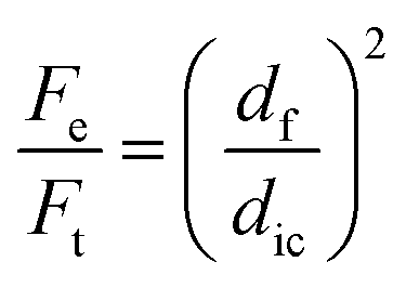
The HIPE fibers were spun by employing a double coaxial laminar flow microfluidic device composed of two pulled inner capillaries (injection and collection inner capillaries) and one regular glass capillary (outer capillary) (Fig. 2a). The two inner capillaries were aligned within the outer capillary to produce a flow-focusing junction where the HIPE fiber is fabricated through the assembly of the emulsion droplets. The injection inner capillary contained the concentrated emulsion, and the outer capillary contained the sheath fluid (acidic water at pH 3). Both the emulsion and sheath fluid were kept at continuous flow. Upon contact with the acidic water, the emulsion droplets lose their electrostatic repulsive interaction as now the carboxylic acid groups become protonated. Upon collision with one another they are ‘locked’ through a combination of van der Waals interactions and hydrogen bonding, hereby producing a uniform fiber composed of emulsion droplets in a continuous manner (see ESI,† Fig. S5). An interesting feature of the produced fiber is that the assembly process is reversible. The addition of a base results in the disintegration of the HIPE fiber into individual emulsion droplets (Fig. 2b, and ESI,† Movie S1). The fabrication of the HIPE fibers by microfluidics raised some challenges initially. First, the capillary was prone to clogging, which leads to limitation on the length of the HIPE fiber that can be created. Furthermore, the HIPE fibers were in their ‘stressed’ state when they are initially exposed to the acidic environment. The ‘stressed’ state HIPE fiber tends to break when moved. The HIPE fibers attain their ‘relaxed’ state with time and, therefore, the fibers were not moved for 30 minutes after exposure to acidic aqueous solution. These issues were overcome by the addition of poly(vinyl alcohol) (PVA) to the sheath fluid, as PVA acts as a lubricant for the fiber extrusion, and matches the viscosity of the sheath fluid with the concentrated emulsion. Thus, the HIPE fiber can be subjected to movement even in its ‘stressed’ state when PVA is present in the system. The addition of PVA in the sheath fluid allows for fabrication of uniform continuous HIPE fibers with ease (see ESI,† Fig. S6). HIPE fibers with desired lengths can be generated by separating the concentrated emulsion into defined segments in the injection inner capillary with air bubbles prior to the exposure to the sheath fluid (Fig. 2c). Interestingly, under the experimental flow conditions we applied, the following simple relationship holds:
 | ||
| Fig. 2 (a) Schematic representation of the fabrication of a microfluidically spun HIPE fiber. The diagram shows coaxial flow channels in the microfluidic device, where the inner and outer capillaries contain concentrated emulsion and acidic water, respectively, in a continuous flow. A continuous HIPE fiber is produced upon exposure of the emulsion to the acidic water. The acidic conditions allow the formation of multiple hydrogen bonds between emulsion droplets, initiating them to assemble into a macroscopic supracolloidal fiber. (b) Photograph of a HIPE fiber in acidic aqueous solution (top left), and disintegration into individual dispersed emulsion droplets upon the addition of base (top right). Scale bars represent 1 cm. Light micrographs of the HIPE fiber under acidic conditions (bottom left) and the disintegrated HIPE fiber under basic conditions (bottom right). Scale bars represent 50 μm and 25 μm, respectively. (c) Photograph of HIPE fibers with uniform length. The HIPE fibers with uniform length were fabricated by utilizing air bubbles as a cutting mechanism. The scale bar represents 0.5 cm. (d) Photograph of an asymmetric Janus HIPE fiber. Scale bars represent 0.1 cm (top) and 300 μm (bottom). (e) Photograph of an asymmetric HIPE fiber consisting of three different sections ‘toothpaste’. Scale bars represent 0.1 cm (top) and 300 μm (bottom). (f) Photograph of a magnetic HIPE fiber attracted by an external magnet (fiber with a slight yellow color – left hand side), and no magnetic response with the non-magnetic HIPE fiber (white color fiber – right hand side). The scale bar represents 1 cm. | ||
In which Fe is the volumetric flow rate of the emulsion, Ft is the combined flow rates of both the emulsion and the outer sheath fluid, df is the diameter of the fiber and dic is the inner diameter of the collection channel. It shows that there is essentially no liquid exchange and that the fiber is composed of 81 vol% oil droplets.
The solid and liquid contents of the HIPE fiber were calculated by monitoring the mass loss at 30–1000 °C by thermo-gravimetric analysis (see ESI,† Fig. S7). The fibers consist of 98.32% liquid (dodecane and water) and 1.68% solid, with a mass percent ratio of 0.70:1 of the polymer (pH-BCP and PVA) to Laponite. The incorporation of PVA into the sheath fluid prevents the HIPE fiber to fully disintegrate into individual dispersed emulsion droplets when base is added. Also, permanently cross-linking the HIPE fiber (fabricated with sheath fluid containing PVA) with calcium ions completely stops the disintegration process of the HIPE fiber under basic conditions.
The HIPE fibers can serve as a carrier for oils and hydrophobic dissolved/dispersed ingredients with various cross-sectional segments, which can be achieved easily by incorporating hydrophobic materials into the oil phase of the emulsion droplets prior to the emulsification process. In order to demonstrate this design concept, we produced a variety of fibers of different colors (employing dyes) (see ESI,† Fig. S8). Asymmetric fibers were also fabricated by providing the injection inner capillary with multiple inlets containing a continuous flow of emulsions loaded with different dyes. These Janus (red and blue segments) and ‘toothpaste’ (white, red, and blue segments) asymmetric fibers are depicted in Fig. 2d and e. The width of each section in the HIPE fiber can be easily changed by varying the flow rate of the concentrated emulsions. HIPE fibers with a magnetic response were also fabricated by the addition of ferrofluid in the oil phase of the emulsion (see ESI,† Fig. S9, and Movie S2). As seen in Fig. 2f, the magnetic HIPE fiber (fiber with a slight yellow color) is attracted by an external magnet, whereas the non-magnetic HIPE fiber (white color fiber) is not subjected to the magnetic forces of the magnet.
The emulsion droplets in the fibers are held together by a continuous honeycomb clay-polymer network. When the HIPE fibers were air dried, hereby removing the water and dodecane through evaporation, the nanocomposite structure was retained with the fibers staying intact. There was a decrease of 22.2% ± 3.2% in the volume of the fiber when dried, and a decrease in the length and diameter of 60% ± 2.84% and 60.7% ± 3.25%, respectively. Therefore, the fiber dries isotropically, as 0.63 = 0.22. The HIPE fiber became more rigid upon drying but remarkably could be bent multiple times without breakage (ESI,† Movie S3). The surface morphology and internal structure of the dried fiber were observed by focused ion beam scanning electron microscopy (FIB/SEM) (Fig. 3). The surface morphology was rough and dotted with pores throughout the surface of the fiber (Fig. 3a), the diameters of the pores being within the dimensions of the original emulsion droplets. The internal structure of the HIPE fiber was exposed through ablation of the surface regions of the HIPE fiber with the ion beam. A highly interconnected honeycomb macroporous structure was observed (Fig. 3b). The internal pores are micron sized almost spherical voids originating from the emulsion droplets (templates) and are interconnected via numerous smaller pores originating from the interstitial spaces due to packing. Owing to the highly porous structure of the dried HIPE fiber, a very light weight material was generated. The structural density of the nanocomposite mesh was determined by pycnometry at a value of 2.04 g cm−3 ±0.02 g cm−3, which aligns with the TGA data stating a mass ratio of Laponite clay (d = 2.65 g cm−3) and polymer (d ≈ 1.2 g cm−3) of 1:0.7. The measured bulk density of the fiber is 0.044 g cm−3, in agreement with the calculated value using the TGA and pycnometry data of (0.0168 × 2.04/0.78) = 0.044 g cm−3, which makes our fiber only approximately 36 times heavier than air. The magnetically responsive HIPE fibers were also dried and retained their magnetic properties (ESI,† Movie S4).
 | ||
| Fig. 3 FIB/SEM micrographs of the dried HIPE fiber. (a) Surface morphology of the dried HIPE fiber. The scale bars represent 325 μm (left hand side), 20 μm (right hand side). (b) The ablation of the surface material to reveal the internal structure of the dried HIPE fiber. The internal structure of the dried HIPE fiber shows a highly interconnected macroporous structure with micron sized almost spherical voids that are interconnected via numerous smaller pores. The scale bars represent 50 μm (left hand side) and 2.5 μm (right hand side). | ||
Our HIPE fibers can be potentially used to deliver oils, for example fragrances or insect repellants. For this purpose we investigated the evaporation of the liquid phases of a series of HIPE fibers at ambient temperature with time, which were ionically crosslinked with different amounts of calcium ions (Fig. 4a). The evaporation profiles show two distinct stages. The first stage (from 0 to ∼120 minutes), represents the evaporation of mostly water from the HIPE fiber. Extrapolation of the stage 2 data to time = 0 s would state that the all the fibers contain approximately 45% dodecane, in contrast with the earlier stated 76 wt% (=81 vol%). The reasons for this are that the fibers are collected/stored in an acidic water bath and are non-drained and, therefore, contain roughly an additional 30 wt% of water. The second stage (∼120 to ∼8000 minutes), refers to the slow evaporation of the oil phase from the HIPE fiber. It is clear that the extent of Ca2+ cross-linking has a marked effect on the evaporation rate of the dodecane. The fibers were post-annealed at 220 °C for 30 minutes to remove remaining traces of water and oil from the HIPE fiber. The mass difference in the HIPE fiber after annealing is caused by the incorporation of calcium chloride into the fiber. The light micrographs of the HIPE fibers (crosslinked at different calcium concentrations) at different points of time and after annealing are shown in Fig. 4b, demonstrating the same effect. The clearer contrast (transition from light to dark) is the result of the higher refractive index difference due to presence of air inside the fiber.
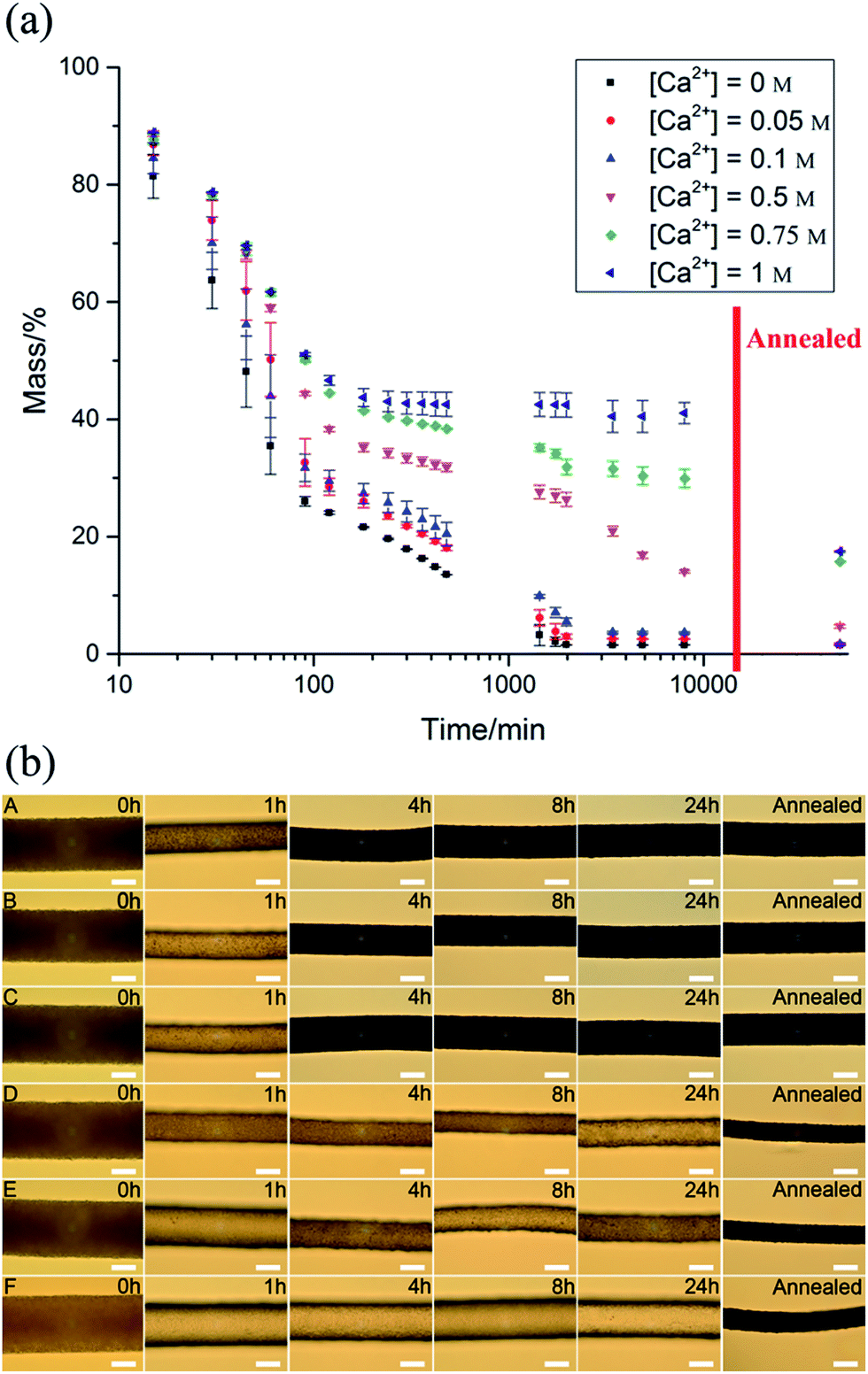 | ||
| Fig. 4 (a) The evaporation of the liquid phases of the HIPE fiber at ambient temperature with time (crosslinked at different calcium concentrations). The mass of the HIPE fiber was recorded over time and annealed at 220 °C to determine the final mass of the dried HIPE fiber. (b) The light micrographs of the HIPE fibers (crosslinked at different calcium concentrations) at different points of time and after annealing (annealed at 220 °C for 30 minutes) ([Ca2+] = 0 M (A), 0.05 M (B), 0.1 M (C), 0.5 M (D), 0.75 M (E), and 1 M (F)). Scale bars represent 100 μm. | ||
Conclusions
We have shown that soft matter fibers can be made through the assembly of emulsion droplets with a potential application as evaporative dispensers. The essential step was to lock the droplets together with a nanocomposite mesh of Laponite clay and hyperbranched copolymer, which possess the capability to undergo secondary interactions (ionic and hydrogen bond interactions). We believe that the use of liquid flow to direct the assembly of colloidal components – in this case droplets – illustrates an innovative pathway to generate supracolloidal structures away from random equilibrium based assembly processes. It opens up an exciting opportunity in the design process of colloidal formulations for a variety of application areas.Acknowledgements
We would like to thank BYK Additives Ltd. for providing the Laponite clay.Notes and references
- F. Vollrath and D. P. Knight, Nature, 2001, 410, 541 CrossRef CAS PubMed.
- G. B. Kauffman, J. Chem. Educ., 1984, 61, 1095 CrossRef CAS.
- C. E. Meihuizen, A. J. Pennings and A. Zwijnenburg, (Stamicarbon, B. V.) US Pat., 4137394, 1979.
- S. L. Kwoleck, (Du Pont) US Pat., 3819587, 1967.
- L. Vollbracht and T. J. Veerman, (Akzo N. V.) US Pat., 4308374, 1981.
- H. Onoe, T. Okitsu, A. Itou, M. Kato-Negishi, R. Gojo, D. Kiriya, K. Sato, S. Miura, S. Iwanaga, K. Kuribayashi-Shigetomi, Y. T. Matsunaga, Y. Shimoyama and S. Takeuchi, Nat. Mater., 2013, 12, 584 CrossRef CAS PubMed.
- Y. Jun, M. J. Kim, Y. H. Hwang, E. A. Jeon, A. R. Kang, S. H. Lee and D. Y. Lee, Biomaterials, 2013, 34, 8122 CrossRef CAS PubMed.
- M. Yamada, R. Utoh, K. Ohashi, K. Tatsumi, M. Yamato, T. Okano and M. Seki, Biomaterials, 2012, 33, 8304 CrossRef CAS PubMed.
- C. M. Hwang, Y. Park, J. Y. Park, K. Lee, K. Sun, A. Khademhosseini and S. H. Lee, Biomed. Microdevices, 2009, 11, 739 CrossRef CAS PubMed.
- J. Puigmartí-Luis, D. Schaffhauser, B. R. Burg and P. S. Dittrich, Adv. Mater., 2010, 22, 2255 CrossRef PubMed.
- D. J. Beebe, G. A. Mensing and G. M. Walker, Annu. Rev. Biomed. Eng., 2002, 4, 261 CrossRef CAS PubMed.
- H. A. Stone, A. D. Stroock and A. Ajdari, Annu. Rev. Fluid Mech., 2004, 36, 381 CrossRef.
- C. M. Hwang, A. Khademhosseini, Y. Park, K. Sun and S. H. Lee, Langmuir, 2008, 24, 6845 CrossRef CAS PubMed.
- Y. Yu, H. Wen, J. Ma, S. Lykkemark, H. Xu and J. Qin, Adv. Mater., 2014, 26, 2494 CrossRef CAS PubMed.
- W. Jeong, J. Kim, S. Kim, S. Lee, G. Mensing and D. J. Beebe, Lab Chip, 2004, 4, 576 RSC.
- C.-H. Choi, H. Yi, S. Hwang, D. A. Weitz and C.-S. Lee, Lab Chip, 2011, 11, 1477 RSC.
- E. Um, J. K. Nunes, T. Pico and H. A. Stone, J. Mater. Chem. B, 2014, 2, 7866 RSC.
- J.-H. Jung, C.-H. Choi, S. Chung, Y.-M. Chung and C.-S. Lee, Lab Chip, 2009, 9, 2596 RSC.
- S. Cho, T. S. Shim and S.-M. Yang, Lab Chip, 2012, 12, 3676 RSC.
- E. Kang, G. S. Jeong, Y. Y. Choi, K. H. Lee, A. Khademhosseini and S.-H. Lee, Nat. Mater., 2011, 10, 877 CrossRef CAS PubMed.
- L. Leng, A. McAllister, B. Zhang, M. Radisic and A. Günther, Adv. Mater., 2012, 24, 3650 CrossRef CAS PubMed.
- E. Kang, Y. Y. Choi, S. K. Chae, J. H. Moon, J. Y. Chang and S. H. Lee, Adv. Mater., 2012, 24, 4271 CrossRef CAS PubMed.
- J. K. Nunes, H. Constantin and H. A. Stone, Soft Matter, 2013, 9, 4227 RSC.
- S. K. Chae, E. Kang, A. Khademhosseini and S. H. Lee, Adv. Mater., 2013, 25, 3071 CrossRef CAS PubMed.
- J. V. M. Weaver, S. P. Rannard and A. I. Cooper, Angew. Chem., Int. Ed., 2009, 48, 2131 CrossRef CAS PubMed.
- R. T. Woodward and J. V. M. Weaver, Polym. Chem., 2011, 2, 403 RSC.
- T. Ngai and S. A. F. Bon, Particle-Stabilized Emulsions and Colloids, The Royal Society Of Chemistry, 2015 Search PubMed.
- L. Rosta and H. R. von Gunten, J. Colloid Interface Sci., 1990, 134, 397 CrossRef CAS.
- R. G. Avery and J. D. F. Ramsay, J. Colloid Interface Sci., 1986, 109, 448 CrossRef CAS.
- E. Balnois, S. Durand-Vidal and P. Levitz, Langmuir, 2003, 19, 6633 CrossRef CAS.
- H. Z. Cummins, J. Non-Cryst. Solids, 2007, 353, 3891 CrossRef CAS.
- A. Mourchid, A. Delville, J. Lambard, E. Lécolier and P. Levitz, Langmuir, 1995, 11, 1942 CrossRef CAS.
Footnote |
| † Electronic supplementary information (ESI) available: Experimental section of the paper can be found in the ESI. See DOI: 10.1039/c5ta08917d |
| This journal is © The Royal Society of Chemistry 2016 |