
 Open Access Article
 This Open Access Article is licensed under a
 Creative Commons Attribution 3.0 Unported Licence
Cylindrical chains of water drops condensing on microstructured lubricant-infused surfaces†
Tadashi
Kajiya‡
a,
Sanghyuk
Wooh‡
a,
Yunchan
Lee
 b,
Kookheon
Char
b,
Doris
Vollmer
a and
Hans-Jürgen
Butt
*a
b,
Kookheon
Char
b,
Doris
Vollmer
a and
Hans-Jürgen
Butt
*a
aMax Planck Institute for Polymer Research, Ackermannweg 10, 55128 Mainz, Germany. E-mail: butt@mpip-mainz.mpg.de
bThe National Creative Research Initiative Center for Intelligent Hybrids & the WCU Program of Chemical Convergence for Energy and Environment, School of Chemical and Biological Engineering, Seoul National University, Seoul 08826, Korea
First published on 2nd November 2016
Abstract
We studied the condensation of water drops on a micro-structured lubricant-infused surfaces. Hierarchical micro-prism surfaces were fabricated by soft imprinting with wet TiO2 nanoparticle paste. After hydrophobization, the patterned surfaces were infused with silicone oil as a lubricant. When cooling at high humidity (over 80%), water drops nucleate and start growing on the surface. Once they have reached a certain size, the drops at neighboring channels of the micro-prisms attract each other and spontaneously form cylindrical chains. These chains of drops align perpendicular to the prism array. The morphology and the length-to-width ratio of the chains of drops depend on the thickness of the lubricant layer. This new concept of water drop alignment on lubricant-infused surfaces offers a new route for pattern formation with condensed drops.
I. Introduction
Condensation of water drops from the atmosphere onto a solid surface is a daily-observed phenomenon. Dew in the morning and fogging of glasses and windscreens are typical examples. Condensation has been generally studied in technological applications for thermal management and heat transfer in power generation1 and continuous water harvesting by dew or fog.2–4Condensed drops are also used to pattern surfaces known as breath figures5,6 and to fabricate micro-particles7. When blowing humid air over a polymer solution whose solvent has a low boiling point and is immiscible with water, evaporative cooling leads to the condensation of water drops at the surface of the polymer solution. These drops can form a hexagonal array. After evaporation of the liquids, a hexagonal array of bubbles is left in the polymer. In this way, regular arrays of pores in a polymer film can be prepared.8,9
Research on the condensation has been extended to lubricant-infused surfaces. These micro- or nano-textured surfaces are infused with a non-volatile lubricant of low surface tension.10–12 A thin lubricant layer covers the solid substrate and is kept in place by capillary forces. When placing a drop of an immiscible liquid on a lubricant-infused surface, the drops slide off at tilt angles of a few degrees.13–15 Anaud et al. and Park et al. have shown the facile collection of condensed drops.16,17 Kim et al. demonstrated the good anti-icing properties,18 as the drops are removed before ice-formation sets in.
In our previous work, we imaged the condensation of water drops onto lubricant-infused square arrays of micro-pillars by confocal microscopy.19 Here, we describe the condensation dynamics of water drops on lubricant-infused porous surfaces with a hierarchical nano- and microstructure. Rather than the 2D regular arrays, we used a 1D symmetry. The surface consists of linear arrays of TiO2 micro-prisms with nanometer-sized porosity, which is infused with silicone oil. While condensing, the water drops aligned perpendicular to the prism arrays and form long cylindrical chains. Micro-structuring the lubricant infused surface leads to the self-assembly of condensing drop. We investigate how the shape of chains depends on the parameters such as the thickness of the lubricant. We also discuss the mechanisms of chain droplet formation.
II. Materials and methods
The micro-prism patterned mesoporous titanium dioxide (TiO2) surfaces (Fig. 1a) were prepared by soft-lithography using wet TiO2 nanoparticle paste, following the procedure described by Kim et al.20 and Wooh et al.21,22 TiO2 nanoparticle paste (18NR-T, Dyesol, particle diameter: 20 nm) was blade coated on a silicon wafer and then gently imprinted with a micro-prism patterned polydimethylsiloxane (PDMS) mold. The PDMS mold consisted of micro-prism pattern with a peak-to-peak distance of 25 μm and a slope of 45°. The imprinted paste was annealed at 70 °C for 10 min to evaporate solvent and to solidify the paste. After detaching the PDMS mold, the patterned TiO2 paste was sintered at 500 °C for 30 min to decompose residual organics. The surface nano-roughness is necessary to keep the lubricant layer on the surface and provide a reservoir of lubricant. The surface was hydrophobized before coating with lubricant in order to prohibit the water drop adhering on the surface. For hydrophobization of the patterned surface, the surface was modified with trichloro(1H,1H,2H,2H-perfluorooctyl)silane by chemical vapor deposition for 2 hours in a pre-evacuated desiccator.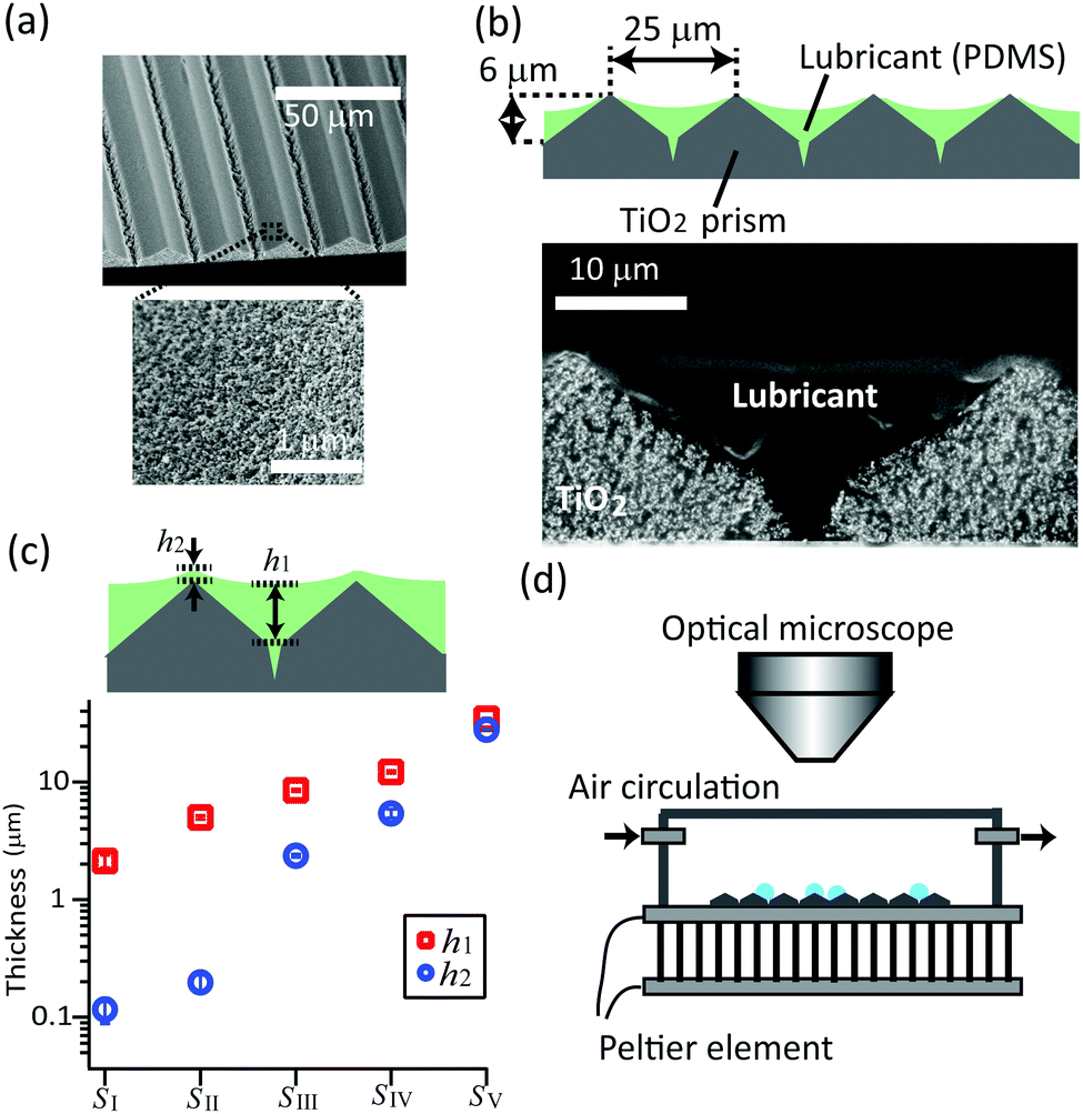 | ||
| Fig. 1 (a) Scanning electron microscope (SEM) images of the micro-prism patterned mesoporous TiO2 surface. The surface consists of a regular array of 2D prism patterns (top) that is mesoporous with ∼10 nm size pores (bottom). (b) Schematic and SEM image of TiO2 surface infused with silicone oil as lubricant. The silicone oil was spin-coated at 5000 rpm for 30 s. (c) Plot of the thickness of lubricant layer. The largest and smallest thickness (h1, h2) are plotted. The sample surfaces are, SI: diluted silicone oil (by THF at 25 wt%) spin-coated at 5000 rpm. SII: silicone oil spin-coated at 5000 rpm. SIII: spin-coated at 3500 rpm. SIV: spin-coated at 2000 rpm. SV: blade coated with 50 μm spacers. The SEM images of surfaces SI (with thinnest lubricant layer) and SV (with thickest lubricant layer) are shown as Fig. S1 (ESI†). (d) Setup for the water drop condensation. | ||
TiO2 micro-prism arrays were infused with silicone oil (molecular weight: 9.7 kDa) by spin-coating for 30 s. The lubricant thickness was controlled by changing the rotation speed (2000, 3500 and 5000 rpm), or by diluting the silicone oil (25 wt%) with tetrahydrofuran (THF). In order to reach a lubricant thicknesses over 35 μm, silicone oil was applied by blade coating with 50 μm spacers.
The thickness of lubricant layers was measured using a cross-sectional scanning electron microscope (SEM, low voltage 1530 Gemini LEO, Zeiss) (Fig. 1b), after crosslinking the silicone oil on the surfaces. To crosslink, vinyl-terminated silicone oil with similar molecular weight (molecular weight: 9.4 kDa, viscosity: 0.2 Pass, DMS-V22 from Gelest Inc.) with a crosslinker (2 wt%, HMS-301 from Gelest Inc.) and a platinum catalyst (0.0125 wt%, SIP6831.2 from Gelest Inc.) was used. This crosslinkable silicone oil mixture was coated on the prism-patterned mesoporous surface and cut after 6 hours of curing at 60 °C. The volume shrinkage after crosslinking was below 1%. The silicone oil infiltrated the porous TiO2 and also covered the micro patterns (Fig. 1b bottom). The thickness of the silicone oil layer at the bottom (h1) and at the top (h2) of prisms are plotted in Fig. 1c. While for sample SI to SIV the thickness varies and h1 is lower than h2, for sample SV the micropattern is fully masked by the lubricant and h1 ≈ h2.
The surface tensions of water (saturated with silicone oil) of γw = 44 mN m−1 and silicone oil (saturated with water) γo = 20 mN m−1 were measured using the pendant drop method (OCA35; DataPhysics, Germany).
Condensation of water drops was monitored using a video microscope (Nikon stereomicroscope SMZ-U with a 2× objective) connected to a CCD camera (Basler, model) (Fig. 1c). The temperature of the substrate was controlled with a Peltier module situated underneath the substrate. The sample was placed in a closed plastic chamber, under which a constant air flow at controlled humidity was circulated. To create an air flow with constant humidity (83 ± 3% at a temperature of 21 ± 1), a stream of dry and humid air (made by bubbling through a bottle filled with water) were mixed at controlled flow rates (20 ± 10 ml min−1 and 220 ± 15 ml min−1). The substrate temperature was cooled down to 1 °C at a cooling rate of 0.25 ± 0.03 °C s−1.
III. Results
Several stages of the condensation process could be distinguished (Fig. 2, supplemental Movie S1, ESI†):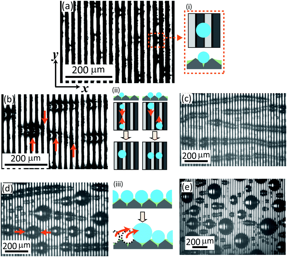 | ||
| Fig. 2 Sequential optical microscope images of the condensing water drops on a prism-patterned lubricant infused surface (surface SIII). Images were acquired after (a) 40 s, (b) 80 s, (c) 120 s and (d) 360 s (e) 1000 s. The x axis is directed perpendicular to the prism lines and the y axis is parallel to the prism. (a) Initially, the drops nucleate randomly on the surface. As the light illuminates from the left top side, the white and black areas corresponds to the left and right flanks of the prisms, respectively (schematic (i)) (b) when the drops grow to a certain size, they interact attractively. Drops nucleated on the same prism line come close and merge (schematic (ii) left). The drops nucleated at the neighboring channels also attract, but they do not coalesce. As a result, they align to the same position on y axis (schematic (ii) right). (c) Finally, the drops form cylindrical chains. (d) and (e) At a last stage, coalescence occurs over the neighboring channel (schematic (iii)). Chains of drops merge to a large spherical drop. | ||
– Nucleation and growth: after cooling was started, tiny water drops (dark elliptical spots) nucleate at random positions on the surface and grow (Fig. 2a). The light is coming from the left top side and illuminates the left flanks of the prisms (white areas). The dark areas correspond to the right flanks of the prisms (schematic (i)). Due to the surface geometry underneath the lubricant, water drops initially condense along the valleys of the prisms and grow individually.
– Attraction and formation of cylindrical chains of drops (Fig. 2b): drops that nucleated in the same valley of the prism come close and coalesce into bigger drops (schematic (ii) left). At the same time, drops in neighboring valleys attract and align at the same y-position. However, they do not coalesce (schematic (ii) right). The drops assemble into long cylindrical chains. In a chain, neighboring drops are separated by lamellae of silicone oil (Fig. 2c).
– Coalescence perpendicular to the prism: once the drops exceed a certain size, the drops within the cylindrically-shaped chains coalesce (schematic (iii)). These larger drops move in x direction and merge with neighboring drops one by one (Fig. 2d and e). When the coalesced drops have reached a radius of 3–5 times the prism spacing (Fig. 2d and e) they get pinned. Then, they only slide at tilt angles above 45°. Coalescence also creates new free surface and fresh nucleation occurs.
The length of the chains of drops lx and width ly are plotted as a function of time (Fig. 3a). lx and ly denote the maximum value measured in the x and y directions for each chain of drops.
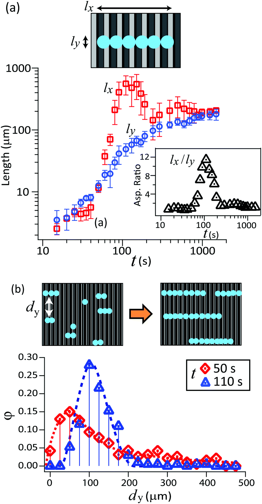 | ||
Fig. 3 (a) Plot of the two mean extension of the condensed drops. As illustrated in the schematic, lx is perpendicular and ly is parallel to the direction of the prisms (with surface SIII, ![[h with combining macron]](https://www.rsc.org/images/entities/i_char_0068_0304.gif) = 4.5 μm). The aspect ratio (lx/ly) is also plotted in the inset. (b) Probability distribution of the spacing between drops in y direction (dy), obtained from multiple data on the surfaces SII and SIII. Initially, the drops are distributed randomly in y direction (left schematic). With the formation of long cylindrical chains of drops, the spacing dy becomes uniform, which is nearly 4 times bigger than the prism gap (right schematic). = 4.5 μm). The aspect ratio (lx/ly) is also plotted in the inset. (b) Probability distribution of the spacing between drops in y direction (dy), obtained from multiple data on the surfaces SII and SIII. Initially, the drops are distributed randomly in y direction (left schematic). With the formation of long cylindrical chains of drops, the spacing dy becomes uniform, which is nearly 4 times bigger than the prism gap (right schematic). | ||
At the early stage when the water drops nucleate and grow individually, the drops have a spherical cap shape. Therefore, the lengths lx and ly increase proportional to each other. The drops start attracting each other when the drop's diameter approaches roughly 5 μm, which is the order of prisms’ height. Drops at neighboring prism channels align at the same y position, forming chains. Meanwhile, the individual drops in a chain grow together. It is not clear yet if the drops in a chain grow independently and just have a similar condensation kinetics, or if they are linked by diffusion of water from one drop to a neighboring one. lx increases much faster than ly at this stage, and the aspect ratio lx/ly exceeds 10. Finally, the chains of drops start to coalesce perpendicular to the prism. The chain-shaped drop transforms into a large spherical cap, therefore the aspect ratio lx/ly approaches unity.
We also analyzed how the drop–drop spacing changes with the creation of cylindrical-shaped chains of drops. For an ensemble of drops, we measured the distance of drops across the y axis (dy). The value dy is measured for adjacent cylindrical chains of drops which have an overlap at the same micro-prism channel. The probability distribution of dy is plotted in Fig. 3b.
At the early stage (t ≤ 50 s) just after the drop starts forming a chain of two or three drops, these drops are separated across the y axis at random. Measured spacing dy is distributed in a broad range. As the alignment of drops continues (t = 50 s), the chains of drops are placed rather uniformly in y direction. The dy distribution shows a sharp peak at dy = 100 ± 5 μm, which is 4 times larger than the pillar gap. To check how the geometry of the prism influences the formation of the cylindrical chains of drops, we condensed drops on lubricant-infused prism arrays with different peak-to-peak distances: 10 μm and 50 μm (Fig. S3, ESI†). The condensed drops form cylindrical chains on all prism sizes. It turned out that the mean spacing dy depends on the peak-to-peak distance of the micro-prism. dy was roughly 4 times larger than the peak-to-peak distance.
IV. Discussion
We suggest that the self-assembly of drops to cylindrical chains originates from the competition between two mechanisms: capillary attraction and topological confinement (Fig. 4a). The high mobility of drops provided by the lubricant is a prerequisite.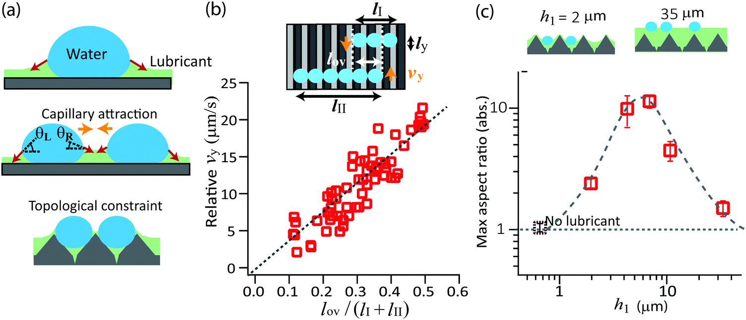 | ||
| Fig. 4 (a) Mechanisms for the line drop formation; capillary attraction by the lubricant meniscus and topological confinement by the prism structure. (b) Relative y velocity (vy) of two cylindrical chains of drops approaching each other. The data are plotted against the ratio of two lengths in x direction; the overlap length (lov) at which the two chains of drops overlap along x axis, and the total length (lI + lII). (c) Plot of the maximum value of the aspect ratio (lx/ly) versus the largest lubricant thickness (h1). To achieve long cylindrical chains, there is an optimal lubricant thickness at 5 ± 2 μm, which is close to the prism height. | ||
On lubricant-infused surfaces, a water drops first nucleate on the free surface of lubricant.19 In the early stage they form a liquid lens. Since the drops are small, one can neglect gravity and the two surfaces are shaped like spherical caps with two radii of curvature. These radii of curvature are given by γw/Rw = γlw/Rlw.19,23 Here, γw is the surface tension of water saturated with silicon oil, γlw is the interfacial tension of the silicone oil/water interface, Rw is the radius of curvature of the top side of the lens and Rlw is the radius of curvature of the bottom side of the lens. After some time the lens has grown into a size that its bottom comes into contact with the TiO2 surface. A solid three-phase contact line forms where the lubricant, TiO2, and water meet. The creation of the solid contact line is indicated by the observation that the water drops do not slide down even when tilting the surface up to 45°.
After the water lens comes into contact with the hydrophobized TiO2, further growth leads to an increase in circumference and in height. The fluid three-phase contact line, where water, lubricant and air meet, is shifted upward. The balance of the interfacial tensions creates the lubricant meniscus, found around the drop's perimeter, which has a negative curvature.24 For isolated drops, the horizontal components of the surface tension of the lubricant/air interface cancel each other when integrating around the fluid contact line.25 The surface tension dragging to the right is equal to the surface tension dragging to the left (Fig. 4a top). When a neighboring drop has grown large enough that the menisci start overlapping, the angle of the interface facing the second drop changes. It changes in such a way that the horizontal component increases (Fig. 4a middle). This leads to a net attractive force. Such phenomenon is similar to the lateral attraction between two particles which are suspended on a free liquid surface.26–28
Suppose that the lubricant fills the spacing between the micro-prisms up to slightly below the peaks of the prisms (surfaces SII and SIII, Fig. 1). When the condensed water drops are smaller than the prism spacing, they are confined between the peaks of prisms. These drops are mobile along the valley of prisms (y direction), but the prism's peak hinders the drops to move perpendicularly (x direction). Meanwhile, the lubricant meniscus reaches the adjacent prism channel. Therefore, the drops in the neighboring channels start attracting each other. As a result, the drops are aligned in the x direction.
For a qualitative evaluation of the velocity, we consider the situation where the two cylindrical chains of length (lI, lII) and of width ly approach each other at relative velocity vy (Fig. 4b). Capillary attraction should occur only when the two menisci overlap. We denote the length where two chains overlap along the x axis as lov. The net attractive capillary force is mainly applied at this overlap region. The capillarity attractive force Fc is approximately given as,
Fc ≈ lovγlub|cos![[thin space (1/6-em)]](https://www.rsc.org/images/entities/char_2009.gif) θL − cosθR|. θL − cosθR|. | (1) |
Here, the angles θL and θR refer to the left and right slopes of the lubricant meniscus at the liquid contact line (Fig. 4a) with the drop and γlub is the surface tension of the lubricant. Following this attraction, the drops move towards each other. The speed is a balance between attraction and viscous friction. Assuming that viscous friction Fv is proportional to the chains lengths,
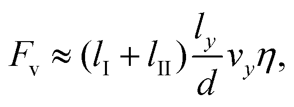 | (2) |
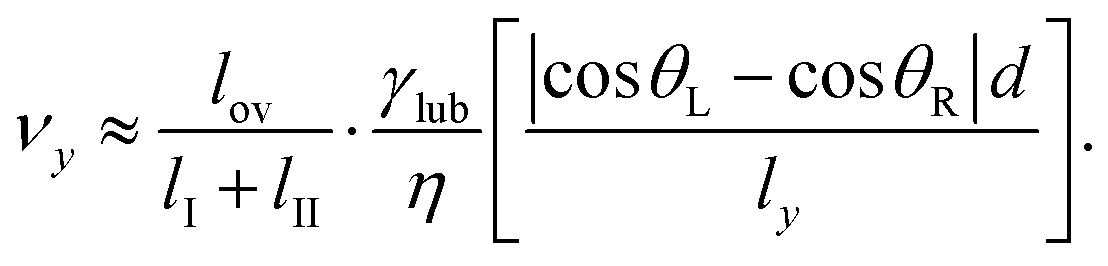 | (3) |
From multiple measurements on the surfaces SII and SIII, we measured the relative velocity (vy) of two chains of drops which are attracting, and plotted as a function of the length ratio lov/(lI + lII). The proportionality was indeed observed (Fig. 4b). The prefactor γlubd|cosθL − cosR|/(ηly) in the example shown in Fig. 4b was 62 μm s−1. With γlub = 0.02 N m−1, η = 0.2 Pa s and ly ≈ 50 μm (twice the spacing of the microstructure) we estimate d|cosθL − cosR| ≈ 3 nm. The angles of the meniscus at both sides of the chains are not largely different and we estimate that |cosθL − cosθR| is of order 0.01 to 0.1. This leads to an estimate for the thickness of the lubricant layer beneath the drop of order 300 to 30 nm, neglecting contributions of the disjoining and Laplace pressure.
The formation of the cylindrical chains of drops is influenced by the thickness of the lubricant (Fig. 4c). If the lubricant thickness is very thin compared to the prism height, the lubricant meniscus does not reach the adjacent prism line. The onset of the attractive movement is delayed. Before the drops attract, they already grow sufficiently large to coalesce over the prism across the x axis. On the other hand, if the lubricant layer is thicker than the prism structure, the whole surface is completely covered. The condensed drops with their respective lubricant menisci are not anymore influenced by the topological confinement set by the prisms. The drops move in all directions, even perpendicular to the prism pattern. Once the drops come close, they simply merge into a large spherical cap drop.
Experimentally, we measured the maximum aspect ratio lx/ly on surfaces with different lubricant thickness, and plotted the maximum ratio as a function of the largest lubricant thickness h1 (Fig. 4c). In order to achieve long chains of drops, we found that there is an optimal thickness of 7–9 μm, which corresponds to the depth of prism channels.
V. Conclusion
Water condensing on lubricant-infused surfaces patterned with linear micro-prisms forms parallel chains of drops. This hierarchical and spontaneous structural formation of water drops is caused by the lubricant film which provides a high mobility of the drops and a long-range capillary attraction. The water drops at the neighboring valleys of micro-prisms attract each other and align perpendicular to the prism array. With optimal lubricant thickness, long cylindrical-shaped chains of drops are formed, which are dispersed quite uniformly across the line. We suggest that such self-assembly of water drops originates from the capillary attraction by the lubricant meniscus and topological confinement set by the prisms. Our results imply that the use of lubricant-infused surfaces with specific surface geometry enables to realize patterns with condensing drops.Acknowledgements
This project was funded by ERC for the advanced grant 340391-SUPRO. DV acknowledges support by COST1106. TK and SW acknowledges support by the Alexander Humboldt Foundation for financial support. TK greatly thanks Masao Doi and François Lequeux for theoretical discussion. KC acknowledges the financial supports from the National Research Foundation of Korea (NRF) for the National Creative Research Initiative Center for Intelligent Hybrids (no. 2010-0018290), the IRTG Program (no. 2011-0032203), and the World Class University Program of Chemical Convergence for Energy & Environment (R31-10013).References
- N. Miljkovic and E. N. Wang, MRS Bull., 2013, 38, 397–406 CrossRef CAS.
- K. S. Udell, Int. J. Heat Mass Transfer, 1985, 28, 485–495 CrossRef CAS.
- A. R. Parker and C. R. Lawrence, Nature, 2001, 414, 33–34 CrossRef CAS PubMed.
- D. Beysens, C. R. Phys., 2006, 7, 1082–1100 CrossRef CAS.
- C. Huang, T. Kamra, S. Chandhary and X. Shen, ACS Appl. Mater. Interfaces, 2014, 6, 5971–5976 CAS.
- A. Zhang, H. Bai and L. Li, Chem. Rev., 2015, 115, 9801–9868 CrossRef CAS PubMed.
- X. Xiong, W. Zou, Z. Yu, J. Duan, X. Liu, S. Fan and H. Zhou, Macromolecules, 2009, 42, 9351–9356 CrossRef CAS.
- U. H. F. Bunz, Adv. Mater., 2006, 18, 973–989 CrossRef CAS.
- H. Bai, C. Du, A. Zhang and L. Li, Angew. Chem., Int. Ed., 2013, 52, 12240–12255 CrossRef CAS PubMed.
- A. Lafuma and D. Quéré, Europhys. Lett., 2011, 96, 56001 CrossRef.
- T. S. Wong, S. H. Kang, S. K. Y. Tang, E. J. Smythe, B. D. Hatton, A. Grinthal and J. Aizenberg, Nature, 2011, 477, 443–447 CrossRef CAS PubMed.
- J. D. Smith, R. Dhiman, S. Anand, E. Garduno, R. E. Cohen, G. H. McKinley and K. K. Varanasi, Soft Matter, 2013, 9, 1772–1780 RSC.
- F. Schellenberger, J. Xie, N. Encinas, A. Hardy, M. Klapper, P. Papadopoulos, H.-J. Butt and D. Vollmer, Soft Matter, 2015, 11, 7617–7626 RSC.
- X. Dai, B. B. Stogin, S. Yang and T.-S. Wong, ACS Nano, 2015, 9, 9260–9267 CrossRef CAS PubMed.
- E. Jenner and B. D’Urso, Appl. Phys. Lett., 2013, 103, 251606 CrossRef.
- S. Anand, A. T. Paxson, R. Dhiman, J. D. Smith and K. K. Varanasi, ACS Nano, 2012, 6, 10122–10129 CrossRef CAS PubMed.
- K.-C. Park, P. Kim, A. Grinthal, N. He, D. Fox, J. C. Weaver and J. Aizenberg, Nature, 2016, 531, 78–82 CrossRef CAS PubMed.
- P. Kim, T.-S. Wong., J. Alvarenga, M. J. Kreder, W. E. Adorno-Martinez and J. Aizenberg, ACS Nano, 2012, 6, 6569–6577 CrossRef CAS PubMed.
- T. Kajiya, F. Schellenberger, P. Papadopoulos, D. Vollmer and H.-J. Butt, Sci. Rep., 2016, 6, 23687 CrossRef CAS PubMed.
- Y. S. Kim, K. Y. Suh and H. H. Lee, Appl. Phys. Lett., 2001, 79, 2285 CrossRef CAS.
- S. Wooh, H. Yoon, J.-H. Jung, Y.-G. Lee, J. H. Koh, B. Lee, Y. S. Kang and K. Char, Adv. Mater., 2013, 25, 3111–3116 CrossRef CAS PubMed.
- S. Wooh, J. H. Koh, S. Lee, H. Yoon and K. Char, Adv. Funct. Mater., 2014, 24, 5550–5556 CrossRef CAS.
- H. M. Princen and S. G. Mason, J. Colloid Sci., 1965, 20, 246–266 CrossRef CAS.
- C. M. Knobler and D. Beysens, Europhys. Lett., 1988, 6, 707–712 CrossRef.
- A. Steyer, P. Guenoun and D. Beysens, Phys. Rev. E: Stat., Nonlinear, Soft Matter Phys., 1993, 48, 428–431 CrossRef CAS.
- W. A. Gifford and L. E. Scriven, Chem. Eng. Sci., 1971, 26, 287–297 CrossRef CAS.
- D. Dushkin, P. A. Kralchevsky, H. Yoshimura and K. Nagayama, Phys. Rev. Lett., 1995, 75, 3454–3457 CrossRef PubMed.
- P. A. Kralchevsky and K. Nagayama, Adv. Colloid Interface Sci., 2000, 85, 145–192 CrossRef CAS PubMed.
Footnotes |
| † Electronic supplementary information (ESI) available. See DOI: 10.1039/c6sm01883a |
| ‡ These authors contributed equally to this work. |
| This journal is © The Royal Society of Chemistry 2016 |