
 Open Access Article
 This Open Access Article is licensed under a Creative Commons Attribution-Non Commercial 3.0 Unported Licence
Durable and scalable icephobic surfaces: similarities and distinctions from superhydrophobic surfaces
H.
Sojoudi
ab,
M.
Wang
a,
N. D.
Boscher
ac,
G. H.
McKinley
*b and
K. K.
Gleason
*a
aDepartment of Chemical Engineering, Massachusetts Institute of Technology, 77 Massachusetts Avenue, Cambridge, MA 02139, USA. E-mail: kkg@mit.edu
bDepartment of Mechanical Engineering, Massachusetts Institute of Technology, 77 Massachusetts Avenue, Cambridge, MA 02139, USA. E-mail: gareth@mit.edu
cMaterials Research and Technology Department, Luxembourg Institute of Science and Technology, 5 Avenue des Hauts-Fourneaux, Esch/Alzette, L-4362, Luxembourg
First published on 30th November 2015
Abstract
Formation, adhesion, and accumulation of ice, snow, frost, glaze, rime, or their mixtures can cause severe problems for solar panels, wind turbines, aircrafts, heat pumps, power lines, telecommunication equipment, and submarines. These problems can decrease efficiency in power generation, increase energy consumption, result in mechanical and/or electrical failure, and generate safety hazards. To address these issues, the fundamentals of interfaces between liquids and surfaces at low temperatures have been extensively studied. This has lead to development of so called “icephobic” surfaces, which possess a number of overlapping, yet distinctive, characteristics from superhydrophobic surfaces. Less attention has been given to distinguishing differences between formation and adhesion of ice, snow, glaze, rime, and frost or to developing a clear definition for icephobic, or more correctly pagophobic, surfaces. In this review, we strive to clarify these differences and distinctions, while providing a comprehensive definition of icephobicity. We classify different canonical families of icephobic (pagophobic) surfaces providing a review of those with potential for scalable and robust development.
1 Introduction
Some reports define icephobicity as low adhesion strength between ice and a solid surface.1–5 Most utilize reduced shear adhesion stress,6,7 but some use reduced normal adhesion strength.8–11 Some other scholars define icephobicity as the ability to delay and prevent ice nucleation and formation on surfaces induced either by pouring a supercooled water12–15 (below the normal freezing temperature of 0 °C) on the substrate or lowering the substrate temperature after a droplet is placed on the surface.16–18 (Such abilities depend on whether a droplet of supercooled water freezes at the interface and can be characterized by the time delay of heterogeneous ice nucleation.) An impact test to examine rebounding droplets has also been suggested, implying that icephobic surfaces repel incoming small droplets (e.g. of rain or fog) at temperatures below the freezing point. By analogy with the classical Greek origins of the etymology for hydrophobic and oleophobic surfaces, we also note here that such diverse phenomena should be gathered under the broad heading of pagophobicity (pagos = ice (Greek)). These different definitions of pagophobicity (icephobicity) correspond to different, although related, properties of anti-icing surfaces.Thus, anti-icing surfaces must display a comprehensive set of characteristics.19 Water in its solid form should be prevented or delayed in forming on such surfaces, or if formed, the rate of accumulation on the surface should be slowed down. Additionally, the adhesion of ice to the underlying substrate should be reduced, such that it can be easily removed. For engineering applications, these attributes are required for ice in its myriad forms. Despite recent advances,20 anti-icing technologies which can prevent or retard formation, adhesion, and accumulation of frost, rime, glaze, bulk ice, and dry/wet snow or their combination are still missing. Practical embodiments of this technology are desired for a wide range of applications including locks and dams,21 solar panels,22 and wind turbines.23 Therefore, the structural and chemical integrity of icephobic surfaces used in practice must be able to withstand erosion, wear, and other weathering conditions. Furthermore, these surfaces must be scalable, inexpensive, environmentally friendly, and mechanically durable.
In this review, we first seek to clarify the differences between ice, frost, glaze, rime, snow, and other forms of solid water which can form from liquid water and/or water vapour under various conditions. Table 1 provides a summarized definition of each type of solid water. In order to study and comprehend the best strategies for developing icephobic surfaces, we initially focus on classifying existing literature based on various aspects of icephobicity in order to enable a valid performance comparison of various methods for making icephobic surfaces. While much of this literature uses rough and dry superhydrophobic coatings directly applied on hard substrates (i.e. steel, aluminum, silicon),15,17,24 other approaches include utilization of liquid-infiltrated porous solids which are wet and smooth4,25–27 or application of viscoelastic rubbers which are soft, smooth, and can be dry16,28,29 or wet (i.e. oil-infused).30
| Frost | Sparse dendritic crystal structures; nucleates from the vapor phase via desublimation or condensation followed by freezing.20 |
| Glaze | Clear, dense, and hard ice; forms from freezing rain of large droplets with diameters ranging from 70 μm to even a few millimetres.20 |
| Rime | White, brittle, and feather-like ice that forms because of freezing of supercooled droplets with diameters in the range of 5–70 μm originating from clouds or fog.20 |
| Snow | A mixture of ice and water. Snow is ‘dry’ when the air temperature is below −1 or −2 °C, but at temperatures closer to freezing point a thin layer of water covers ice, creating wet ice with properties between ice and water. |
| Ice | A brittle frozen state of water which can appear transparent or a more or less opaque bluish-white color depending on the presence of impurities such as particles of soil or bubbles of air. |
Superhydrophobic surfaces, i.e. those characterized by high water contact angle (WCA) and low WCA hysteresis with air pockets trapped between water and the underlying surface texture, have shown promising anti-icing performance.1,9,19 Superhydrophobic surfaces have been observed to enhance the rebound of incoming droplets at low substrate temperatures and high relative humidity.31 Additionally, such coatings have been reported to provide reduced normal and/or shear adhesion of ice to the underlying surface,9 to result in a delay in water freezing on surfaces,12 and to reduce or even completely inhibit nucleation and accumulation of ice and/or snow on surfaces.32,33 However, some other studies challenge the icephobic performance of superhydrophobic surfaces in high relative humidity environments.5,14,34 Despite recent advances,20 anti-icing technologies which can prevent or retard nucleation, adhesion, and accumulation of frost, rime, glaze, bulk ice, and dry/wet snow or their combination are still missing. For practical icephobic applications, the surfaces have to withstand erosion, wear, UV radiation, and other weathering conditions in terms of their structural and chemical integrity. Furthermore, for commercial adoption, the engineered surfaces have to be inexpensive, environmentally-friendly, and enable scalable manufacturing. While previous reviews of icephobicity or pagophobicity have been inspired from biology for surface design,10 or relied on construction of superhydrophobic surfaces for icephobic applications,35 or considered the design of surfaces based upon thermodynamic and fluid mechanical considerations,36 this paper focuses on elucidating the broad definition of icephobicity while reviewing the available methods for manufacturing of scalable and durable pagophobic surfaces.
2 Definition, classification, and performance comparison of pagophobic surfaces
2.1 Classification of pagophobic surfaces based on various surface attributes
Questions concerning correlation of surface characteristics (i.e. roughness, chemistry, porosity) and icephobicity are not clearly answered yet. This is due to different prevailing definitions of icephobicity and proposed test methods to evaluate icephobic performance of a given surface. For example, those scholars who consider a reduction in ice adhesion strength as icephobicity, have primarily identified superhydrophobic surfaces as potential candidates for icephobic applications.3,18,24,37 However, depending on the measurement method, the prevailing icing conditions, and surface topography, other researchers have demonstrated contradictory results showing that textured superhydrophobic surfaces can increase the strength of ice adhesion.5 Another discrepancy arises between those who consider repelling droplets of supercooled water as a key feature of icephobicity. Based on this definition, a superhydrophobic surface does not ice if a supercooled droplet falls on it from a relatively large distance as the droplet will bounce off very rapidly before freezing. However, such superhydrophobic surfaces can readily be iced by immersion in supercooled water. Therefore it is essential to understand differences in pagophobic test methods and the state of substrates under these test conditions.In this review, the first important consideration is the relative humidity of the atmosphere when examining icephobicity of surfaces. Farhadi et al. have shown that the strength of ice adhesion increases three-fold when water vapor condenses on the surface as occurs for example under conditions of high humidity.24 Additional considerations include the surface topography (whether it is smooth or rough), liquid extent (whether it is dry or wet due to infiltration of a secondary liquid), and elasticity (whether a surface coating is directly applied to a hard substrate such as aluminum and steel or whether an intermediate soft elastomeric layer has been incorporated). Fig. 1a shows a schematic of how we classify icephobic coatings based on three distinctive surface attributes: elasticity (soft vs. hard), topography (smooth vs. rough), and liquid extent (dry vs. wet). Later, we will discuss different aspects of icephobicity using this classification to review recent advancements in the literature. These distinctive characteristics are also related to differences in the formation mechanism of ice, frost, snow, or their combination on smooth vs. rough, dry vs. wet, or soft vs. hard surfaces which can lead to differences in their icephobic performance. For example, Varanasi et al. have shown that frost can readily form everywhere on a rough superhydrophobic surface at relatively high humidity and the subsequent adhesion of ice on that surface is substantially higher than on a smooth substrate, suggesting superhydrophobic surfaces are not appropriate for icephobic applications.5
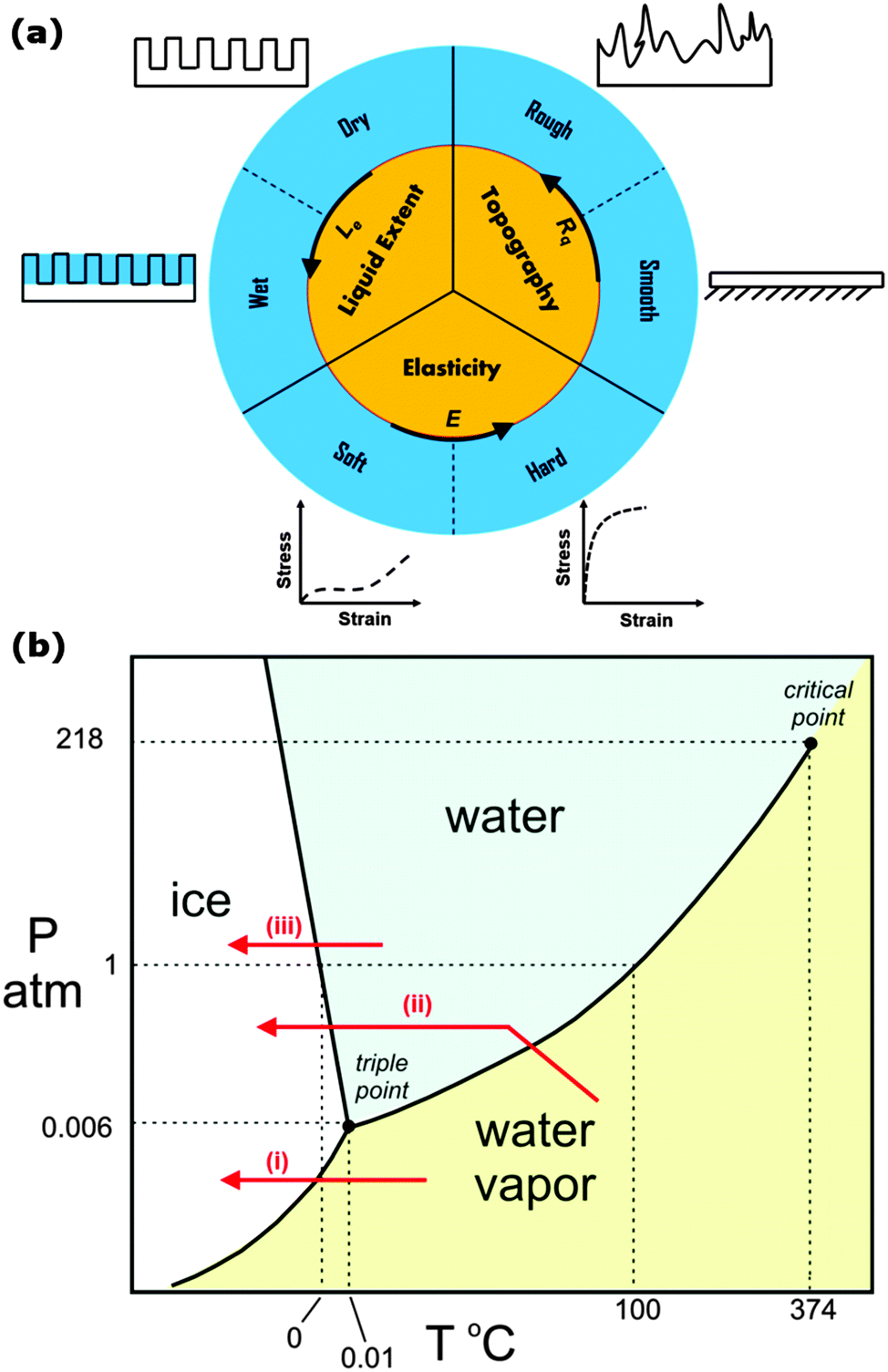 | ||
| Fig. 1 (a) A framework for classifying recently developed icephobic coatings. (b) Phase diagram for water indicating three different pathways for formation of water-based solid by changes in temperature and/or pressure of water. (i) Vapor–solid desublimation deposition, (ii) vapor–liquid–solid or condensation followed by freezing, and (iii) liquid–solid or freezing. | ||
Icephobic coatings are mostly developed based on inspiration from traditional superhydrophobic surfaces which are rough and dry. We will discuss this traditional category in detail in Section 2.2. A radically different class of ice-repellent materials have been developed that present a dynamic, molecularly smooth liquid interface which promotes liquid mobility retarding the pinning of freezing water droplets and showing dramatic reduction in ice adhesion and droplet retention size.25,26 These surfaces have been inspired by Nepenthes pitcher plants and created by infiltrating a micro/nanoporous substrate with a non-freezing lubricating liquid to produce a thin, ultrasmooth lubricating layer that enhances surface mobility of liquid drops. The approach is based on a uniform and flat liquid interface that minimizes contact angle hysteresis (i.e. the difference between advancing and receding contact angles) and therefore reduces the occurrence of pinned water droplets and their subsequent freezing on sub-cooled solid substrates. We categorize these slippery liquid-infused porous surfaces (SLIPS)26,38 as smooth, wet, and porous coatings developed on hard substrates to create icephobicity. It has also been reported that these SLIPS-coated surfaces show significantly increased supercooling performance and no detrimental effects after 150 freeze–thaw cycles.26 Even in a high humidity environment (e.g., 60% relative humidity), SLIPS-coated substrates remain ice/frost repellent by effectively shedding condensed water droplets. Varanasi and co-workers have found that external forces such as gravity can drain the excess liquid to attain a thermodynamically stable configuration of the surface.4,39 However, driven by capillary attraction, lubricant could be gradually depleted during deicing or defrosting cycles and SLIPS-coated surfaces can fail to provide lubrication under extended operation.10 More recently, Aizenberg and co-workers have reported that the thermodynamic stability of SLIPS can be improved by employing a closed-cell architecture.40 In general, the liquid layer is utilized to decrease or eliminate the interaction between the surface and ice so that the ice layer can be easily removed. Stone has highlighted the importance of SLIPS-coated surfaces for icephobic applications in a perspective article and has raised questions about the performance of these surfaces when extreme surface shear stresses are present and under laminar and turbulent flows.27
The coatings discussed above have been categorized based on their surface attributes (smooth vs. rough or dry vs. wet) and are typically applied to rigid substrates in order to obtain pagophobic characteristics. The third surface attribute for classification of icephobic coatings is the elasticity of the base layer (i.e. is the coating directly applied to a hard substrate or is a soft relatively thick layer used as a sacrificial base layer in order to intrinsically enhance icephobicity). In this regard, viscoelastic rubbers primarily formulated from low Tg silicones have been used as soft, tough, and smooth materials to promote icephobicity. Silicones are polymers that include any inert and synthetic compound made up of repeating units of the siloxane moiety (which is a functional group of two silicon atoms and one oxygen atom frequently combined with carbon and/ or hydrogen). Functional organic constituent are groups such as methyl, phenyl or trifluoropropyl moieties. Traditionally silicone has been used to make ice cube trays and flexible molds. Silicone films can also be applied to such silica-based substrates as glass to form a covalently bonded hydrophobic coating. Viscoelastic coatings based on polydimethylsiloxane have shown icephobic characteristics due to the combination of their low surface energy and outstanding elasticity. These silicone coatings have provided reduction factors up to 100 in the adhesion strength of ice to aluminum substrates.16
The use of silicone as an icephobic coating for a range of different surfaces has been promoted by Nusil Silicone Technology® (http://www.nusil.com).28 Susoff et al. have used Nusil R-1009® to obtain icephobicity with a lowered shear adhesion strength of 37 kPa. Nusil R-1009® is a one-component condensation curing silicone system that does not need any adhesion promoter. The coating can be applied by dip-coating from a 50 wt% solution in toluene followed by curing for two days at ambient temperature in the presence of air humidity. AMES Shield is another pioneering company which develops elastomeric ice-phobic coatings (http://www.amescorp.com).41 Their elastomeric coating has been custom formulated for unique application with base elastomers ranging from natural rubber composition, that are resistant to acids and bases, to exotic blends of high performance materials such as fluoroelastomer and fluorosilicone. Fluorosilicone-containing block copolymers have also been utilized as dry and smooth coatings to delay icing time at −15 °C temperature and to lower the ice shear adhesion strength to approximately 300 kPa.29 These are all examples of soft, smooth, and dry icephobic coatings. Silicone rubber coatings doped with titania or ceria nanopowders have also been prepared by spin-coating hexane-diluted suspensions onto aluminum substrates. These soft and dry coatings, are given a roughened texture by the nanoparticles, and this results in approximately 12–13 minutes delay in freezing water droplets.42
Elastomeric soft materials have also been used as sacrificial layers to promote icephobicity. Zhu et al. have introduced a composite liquid/solid material analogous to SLIPS surfaces based on silicone-oil-infused polydimethylsiloxane (PDMS) for ice-phobic coatings.30 The very large free-volume in the PDMS at ambient temperature acts as void space to accommodate the infused silicone oil. The result is a smooth, wet, and soft hydrophobic surface which has superior icephobic performance in low temperature and high humidity environments (and an ice adhesion strength of 50 kPa, only about 3% of the value on a bare aluminum). Dou et al. have also used an aqueous lubricating layer on a porous elastomer as a smooth, wet, and soft anti-icing coating. They have used polyurethane as the porous base due to its adhesiveness to a variety of substrates.43
2.2 From superhydrophobicity to icephobicity
Superhydrophobic surfaces mimicking lotus leaves and water strider legs are commonly designed to have topography on the micro to nanoscale which enables the entrapment of air between the surface texture and the overlying liquid (i.e. the Cassie or Cassie–Baxter state,44Fig. 2a). These surfaces naturally offer potential for pagophobic applications, where typically a rough coating is deposited on a hard substrate. During supercooling, trapped air in the surface textures of solid substrates can result in bouncing off or of “trampolining” the impacting and condensed water droplets before freezing. Liquid droplets on a rough substrate can also exist in the Wenzel state,45,46 where the liquid droplet displaces the air to fully wet the substrate. While some researchers have shown a transition from a Cassie–Baxter state to a Wenzel state when ice forms (Wenzel ice, Fig. 2a), others have claimed that a lower ice adhesion strength on superhydrophobic surfaces is indicative of water freezing in the Cassie–Baxter state and formation of a ‘Cassie ice’ or frost.47 Meuler et al. have argued that effective icephobic surfaces must resist transitions to the fully wetted state that may be brought about by the kinetic energy of impinging water droplets or by the condensation of moisture from the ambient atmosphere within the micro and/or nano texture of the substrate.47 In a Cassie ice state, the real contact area between ice and the solid substrate is reduced, resulting in reduction in the ice adhesion strength (Fig. 2b) whereas in a Wenzel ice state, the real contact area is increased due to surface topography, leading to an increase in the total ice adhesion strength. | ||
| Fig. 2 Various anti-icing technologies. (a) Schematic of a water droplet in the Wenzel vs. Cassie–Baxter state before freezing and possibility for formation of Wenzel ice or Cassie ice during sub cooling. (b) Water droplet in Cassie–Baxter state turns into Cassie ice on a superhydrophobic surface.17 (c) A bare aluminum substrate (left) and an aluminum substrate covered with a superhydrophobic coating (right) after “freezing rain.” So called “glaze” formation is less pronounced on the coated substrate.13 (d) Frost nucleation and growth occurs without any particular spatial preference on a superhydrophobic surface resulting in an increase in the ice adhesion strength.5 (e) Drop-by-drop accumulation and freezing of a growing supercooled water on a coated substrate; horizontal dashed line indicates crystallization front which starts at the liquid–solid contact area and gradually advances upward leading to an “ice finger.”14 (f) Outdoor test of comparative behavior of a coated (top) and bare (bottom) stainless steel in heavy snowfall at −3 °C, relative humidity of 99%, and wind velocity of 2 m s−1.64 Figures reproduced from5,13,14,17,64 with the permission of AIP, ACS, ACS, Elsevier, and ACS, respectively. | ||
Overall, the thermodynamic stability of surface superhydrophobicity under common engineering applications, which often involve high velocity water droplet impact, high humidity, or variable temperatures, has posed significant challenges in the field of icephobicity. Therefore, the pagophobic performance of a superhydrophobic surface must be discussed carefully based on different definitions of icephobicity and characteristic testing conditions. For example, it has been shown that superhydrophobic surfaces with low surface energy and rough textures can prevent ice formation only in a frost-free environment.25 Under high humidity conditions, these surfaces can induce ice nucleation at an even faster rate than smooth surfaces constructed from the equivalent materials due to their high surface area and increased nucleation site density. An alternative strategy has been proposed to simultaneously utilize superhydrophobic coatings along with de-icing systems in order to enhance shedding of water and removing extant ice/frost from the surfaces. Antonini et al. have shown that this combined strategy can reduce the energy required to avoid ice accretion on airplane wing by up to 80%.48 In summary, due to the lack of a unique definition for pagophobic surfaces and a plethora of pagophobicity test conditions, superhydrophobic surfaces might or might not be suitable for icephobic applications. In the following sections we will provide examples based on different characteristic measures and definitions of pagophobicity and will elucidate their differences.
2.3 Icephobicity based on ice nucleation mechanism and freezing delay
Researchers who study ice nucleation mechanisms define icephobicity as an ability to prevent or delay ice nucleation and deposition on surfaces. This ability depends on whether a droplet of supercooled water (below the normal freezing temperature of 0 °C) freezes at the interface and it can be characterized by a time delay for heterogeneous ice nucleation. Schutzius et al. have reviewed the fundamentals of nucleation and freezing delay, concluding that the nucleation temperature is relatively insensitive to surface nanoroughness, when surfaces have only a fraction of the area occupied with nanoscale pits below 10rc (a critical stable radius).36 They also found that an extraordinary delay in heterogeneous nucleation can be theoretically achieved by designing a surface composed of an array of nanoscale pits with small asperities, taking advantage of the presence of the quasi-liquid layer and the freezing-point depression of water.49 Keeping the radius of curvature of the rough bumps in contact with water smaller than the smallest stable ice nuclei formed increases the energy barrier for ice nucleus formation (and thus retards icing). Superhydrophobicity and pagophobicity can be linked where ice nucleation delay is the subject of interest by maximizing the solid–air fraction of the surface through enhanced topography. This roughness results in a reduction of the wetted area fraction which results in a reduction in the heat transfer and the probability of heterogeneous nucleation at the water–solid interface.32,35Conversely, Wilson et al. have suggested that ultra-smooth and chemically homogeneous interfaces of lubricant-based surfaces can also minimize or fully prevent icing by reducing the number of potential sites for nucleation.26 Based on classical nucleation theory-based analysis, Alizadeh and co-workers32,35 have estimated various homogeneous and heterogeneous nucleation rates under icing conditions as a function of surface wettability. They have found that the ice nucleation delay due to reduced water–solid contact area is prominent only at moderate degrees of supercooling; at supercooling temperature of closer to −40 °C (the homogeneous nucleation temperature of water), nucleation effects in bulk and at the air–water interface become equally important. Considerable freezing delay times, in a temperature range above the heterogeneous ice nucleation temperature (−40 °C), were obtained with an icephobic surface that was designed according to the above mentioned principles. Schutzius et al. have also shown that rational design frameworks can be used to systematically develop icephobic surfaces for inhibiting heterogeneous nucleation and promoting a freezing delay.36
2.4 Icephobicity based on freezing rain, supercooled droplet rebound, and supercooling of static droplets
Some naturally-occurring icing events are induced by impact of supercooled water droplets onto surfaces, and are commonly referred to as “freezing rain”, “atmospheric icing,” or “impact ice.”13 A clear, dense, and hard ice, known as “glaze”, can be formed due to freezing rain which consists of large water droplets with diameters ranging from 70 μm to a few millimetres.20 Smaller size supercooled droplets (with diameters in the range of 5–70 μm) which originate from clouds or fog can form a white, brittle, and feather-like ice, called “rime.”20 Some researchers have examined the superhydrophobicity of surfaces under extremely condensing conditions (−10 °C and relative humidity of 85–90%) and demonstrated they can also have ice-repellent character.11 The surface is referred to as ice-repellent (or pagophobic) when supercooled droplets of water at −10 °C and relative humidity of 90% bounce off the surface easily. Parameters such as droplet size, liquid surface tension, and impact velocity (ϑi) are the key factors in determining the droplet dynamics. A dimensionless number, the Weber number (We), can be used to examine the dynamics of droplets: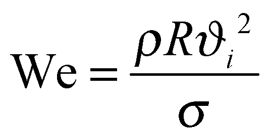 | (1) |
 | (2) |
Researchers have also discussed the key role of viscous dissipation of impact kinetic energy of water droplets during the spreading. When the energy dissipation during spreading is not too large, a fraction of the stored surface energy can be converted into kinetic energy and leads to droplet retracting and rebounding. If viscous effects dominate, the droplet remains pinned on the surface instead of fully retracting and rebounds before energy expends. Bird et al. have developed superhydrophobic surfaces with a surface topography that redistributes the liquid mass in the drop and thereby alters the drop hydrodynamics to reduce the contact time of a bouncing drop below the theoretical limit based on the Rayleigh time scale.51 On the other hand, the rate of ice formation speed in a supercooled water droplet on a solid surface depends on the growth rate of crystal nuclei. Ice formation in a supercooled water droplet on a subzero surface can be delayed but not fully prevented. Mishchenko et al. have shown that water droplets impinging on superhydrophobic surfaces can exhibit an anti-icing behavior if the time scale for droplet spreading and retracting from the surface is smaller than the ice nucleation time.31 Wang et al. have demonstrated a sliding angle of 22° under extremely condensing condition (−10 °C, relative humidity 90%), where both single and successive supercooled water droplets could rebound on the surface and roll off the surface at a tilt angle larger than 30°.11 They have also studied the role of droplet velocity, size, and test conditions (temperatures and relative humidity) and have shown that water droplets at Weber numbers as small as We = 0.8 can roll off these superhydrophobic surfaces at tilt angles of 10° at −10 °C temperatures and 85–90% RH, concluding that these surfaces could be ice-repellent.
Schutzius et al.,36 in their earlier review article, have highlighted the importance of droplet mobility at low temperatures concluding that for droplet impact, minimizing the contact time between substrate–supercooled water reduces the probability of droplet freezing. They also note that at low temperatures, the increased viscosity of water can affect the recoil dynamics of droplets impacting surfaces, and specifically the substrate–water contact time. This effect becomes dramatic when the impact velocity is sufficient to cause the liquid meniscus to partially penetrate the surface texture. By reducing the gap between surface features and moving towards nanotextured topography, one can minimize the potential for partial impalement of the water meniscus during drop impact. Similar to ice nucleation delay, the performance of superhydrophobic surfaces can be severely degraded in an environment where frost can form. In addition, the intervening gas layer between a substrate and an impacting water drop plays a very important role in drop dynamics and whether a drop will cause a transition from Cassie–Baxter to Wenzel state.31
Qualitative comparison of water freezing delays on untreated and coated surfaces have been investigated to examine the pagophobicity of surfaces (Fig. 2c).13,14 For example, Jung et al. have inkjet-deposited supercooled microdroplets allowing coalescence until spontaneous freezing of the accumulated mass occurs.14 They have shown that while hydrophobic surfaces show higher resistance to icing than rough hydrophilic surfaces, hydrophilic surfaces with roughness values close to the critical nucleus radius display an order of magnitude longer freezing delay times than typical hierarchically rough superhydrophobic surfaces.14
Freezing has also been studied for room temperature liquid droplets placed on subcooled surfaces. By analogy to the explanation for the ice nucleation delay, Tourkine et al. have proposed that the changing dynamics are due to a layer of air in the voids of a rough superhydrophobic coating that creates a thermal barrier which insulates the liquid from the surface, thus delaying freezing of a water droplet.12 In addition, Alizadeh et al. have suggested that the delayed freezing is induced by both a reduction of the water–solid interfacial area and an increase in nucleation activation energy, which are characteristics of high water contact angles on hydrophobic surfaces.32 In a more comprehensive study, Mishchenko et al. have studied freezing of static water droplets resting on supercooled surfaces as well as behavior of droplets dynamically impacting supercooled nano- and microstructured surfaces.31 They have shown a 16 second time delay for freezing of static water droplets on a low surface energy nanostructured silicon surface when compared to a bare silicon substrate. They have also shown the ability of these surfaces to remain ice-free down to temperatures of ca. −25 °C to −30 °C, as impacting droplets repel before ice nucleation occurs. The appropriate definition of icephobicity among these researchers therefore refers to surfaces which repel incoming water droplets (e.g. those originating from rain or fog) at temperatures below the freezing point or surfaces that delay and/or prevent freezing of static water droplets resting on those surfaces (Fig. 2e).14,19
2.5 Icephobicity based on frost formation or dew condensation
Vapor phase desublimation or condensation followed by freezing leads to formation of sparse dendritic crystal structures that become denser with time, commonly known as “frost.”20 Water vapor condensation is commonly observed in nature and in daily life as well. When the air temperature drops below the dew point, water vapor in the air becomes liquid and condensation occurs. Furuta et al. have shown a decrease in the water contact angle with decreasing surface temperature in a humid environment, suggesting a mode transition from Cassie–Baxter to Wenzel on a cold rough superhydrophobic surface.52 They observed a change of interfacial free energy of the solid–gas interface by water adsorption. This transition in the wetting state is likely due to the capillary condensation of liquid water in the crevices of the textured surface. For icephobic applications in a humid environment it is crucial to prevent this transition in order to prevent formation of so-called “Wenzel ice.” Wang et al. have developed superhydrophobic surfaces which retain water contact angles larger than 150° over a wide temperature range from −10 °C to 17.5 °C in an artificial climate chamber, suggesting their potential for icephobic applications. However, water vapor can desublimate onto a surface at low temperatures and directly form ice crystals or frost. Varanasi et al., have shown how frost formation can alter the wetting properties of a rough superhydrophobic surface, making it increasingly hydrophilic, causing a Cassie–Baxter to Wenzel wetting transition for impacting drops, with subsequent pinning and formation of “Wenzel” ice on the surface (Fig. 2d).5 Similar to the delay in freezing of water droplets, frost formation can be delayed as well. Liu et al. have shown a delay of 55 minutes in frost formation on superhydrophobic surfaces when compared to bare copper surfaces. They have also shown that the frost formed on superhydrophobic surfaces is weaker, looser, thinner, and easy to remove.53 Cai et al. have also shown a delay in frost formation on hydrophobic-coated surfaces when compared to bare surfaces. They also found that the frost formed on coated surfaces is less thick with sparse distribution and less deposition of ice crystals.54Lv et al. have discussed how self-removal of condensed water droplets is important before heterogeneous ice nucleation could occur.10 On superhydrophobic surfaces, condensed droplets with a size comparable to the capillary length may be removed under gravity via tilting the surfaces. However, the condensed microdroplets usually stay and ultimately freeze on the surfaces. Wang et al. have successfully enhanced the self-removal efficiency of condensed water microdroplets under high supersaturation by exploiting the pinning effects of the three phase contact line.55 A series of micropore arrays on nanostructured superhydrophobic surfaces are utilized to achieve this unique self-removal of microdroplets. In addition, it has been shown that frost growth can be delayed via self-removal of condensed water microdroplets by limiting the formation of interdrop ice bridges.56 In this context, icephobicity refers to the ability of surfaces to prevent or delay formation of frost and sometimes to the ability of textured surfaces to prevent the Cassie-to-Wenzel transition during supercooling or during Wenzel ice formation.
2.6 Pagophobicity based on ice adhesion
Lowering the adhesion of previously formed ice is critical as it can then be shed from the surface by action of wind, gravity, or vibration. Menini et al. have noted that interactions between ice and substrate is a combination of electrostatic forces, hydrogen bonding, van der Waals forces, and mechanical adhesion.57 At the atomic or molecular level, short range interaction forces are present such as covalent, electrostatic, and/or metallic forces (e.g. van der Waals forces). Mechanical adhesion may also occur due to mechanical interlocking of microscopic asperities at the interface between two materials.57As with the other aspects of pagophobicity explained earlier, it is also important to consider stability of the Cassie–Baxter wetting state on a superhydrophobic surface in the context of discussing ice adhesion strength. A Cassie–Baxter to Wenzel state transition can happen in a humid environment and if a droplet freezes in this condition, the adhesive strength of the resulting Wenzel ice on this rough substrate can be higher than on a smooth substrate. It is to be noted that only under fully oversaturated conditions would water vapor from the environment heavily condense inside the micro/nanostructure of a superhydrophobic surface, and the condensed water then takes the place of the air cushion. Chen et al. have shown that when this happens superhydrophobic surfaces do not reduce ice adhesion.34 Using a set up similar to the one described in Meuler et al.,3 they demonstrated that ice adhesion on textured superhydrophobic surfaces was comparable to that on superhydrophilic surfaces partially due to a mechanical interlocking between the ice and the surface topography.34 Li et al. have shown that the slipperiness of the ice surface can become important due to a lubricating layer of water on the surface which can originate from pressure-induced melting, frictional heating, and intrinsic premelting.58 This can impact the adhesion of previously-formed ice on various surfaces. Among these researchers, pagophobicity means reduced ice adhesion strength to a solid surface in shear or tensile adhesion experiments.
McKinley and co-workers have shown in a series of studies that the strength of ice adhesion on surfaces correlates well with the work of adhesion between a corresponding liquid droplet and underlying substrate.3,59 The work of adhesion between a liquid droplet and the underlying substrate can be calculated from the Young–Dupré equation as suggested by Gao and McCarthy:45,60
Wadh = γLV (1 + cos![[thin space (1/6-em)]](https://www.rsc.org/images/entities/char_2009.gif) θR) θR) | (3) |
Another source of discrepancy in evaluating pagophobicity based on ice adhesion strength might arise from differences in protocols for measuring the ice adhesion strength (in either shear or tension or mixed mode fracture). Some groups form ice on a rotating horizontal beam in a centrifuge apparatus,2 while others measure the shear strength for propelling ice off from the substrate,62 or measure the shear force for detaching ice formed between a (inner) cylindrical pin and (outer) cylindrical mould.16 For such researchers, pagophobicity implies a reduction in the normal and/or shear adhesion strength of ice through surface coating and/or texturing.
2.7 Icephobicity based on snow accumulation and adhesion
Snow is generally a mixture of ice and water and its adhesion to surfaces is affected by composition, the roughness/texture of the surface, atmospheric temperature, and wind velocity.22 At temperatures below −1 or −2 °C snow is dry but at higher temperatures a thin layer of water covers ice, creating wet ice or snow with intermediate properties between ice and water. The water content (wet vs. dry), surface properties (roughness, composition, heat capacity), ambient conditions (atmospheric temperature, wind velocity, wind direction, diurnal duration), and settling conditions (height, direction, angle) affect snow adhesion.63 Nakajima et al. have shown accelerated sliding of dry snow on a superhydrophobic surface and effective sliding of wet snow on a hydrophilic surface. They inferred that the sliding characteristics of dry snow and wet snow are governed by solid–solid friction and viscous flow, respectively. They have also demonstrated that the sliding characteristics of wet snow can be controlled by introducing hydrophilic channels to a superhydrophobic surface, suggesting surfaces with a reversible wettability switching property between superhydrophobicity and superhydrophilicity for anti-snow adhesion applications.63Fig. 2f shows the comparative behavior of an untreated and treated stainless steel in heavy snowfall at −3 °C.64 The significant difference in performance is due to the fact that heavy wet snow fall onto untreated steel remains fixed on the surface, followed by accumulation whereas the low adhesion of snow to the superhydrophobic surface contributes to its spontaneous removal under wind load and/or vibration of the test stand.Table 2 presents a list of the state-of-the-art pagophobic surfaces, which are guided by the aforementioned definitions, performances, and surface attributes of the coatings. Again, it should be noted that ice adhesion data in Table 2 were obtained with widely different testing methodologies. Furthermore, experimental protocols with regard to droplet freezing, frost formation, snow accumulation/adhesion, and ice/frost nucleation are not the same for all studies. Despite these differences, we believe that representing all of the data from literature in this format helps to elucidate the strength and shortcomings of different pagophobic surfaces.
| Ref. | Icephobic property | Icephobicity test | Pagophobic performance | Durability/scalability | Surface attributes |
|---|---|---|---|---|---|
| Wang et al.17 | Ice nucleation delay | Static droplet at −8 °C | 400 s on bare vs. 520 s on coated | —/✗ | Rough/dry/hard |
| Liao et al.15 | Supercooled droplet at −7 °C | 86 s on bare vs. 475 s on coated | ✓/✗ | Rough/dry/hard | |
| Mishchenko et al.31 | Static droplet at −20 °C | 16 s delay on coated | —/— | Rough/dry/hard | |
| Guo et al.145 | Static droplet at −10 °C | ∼7000 s delay on coated | ✓/— | Rough/dry/hard | |
| Jung et al.14 | Supercooled microdroplets | 800 s delay on coated | —/— | Rough/dry/hard | |
| Li et al.29 | Supercooled droplet at −15 °C | 186 s delay on coated | —/— | Smooth/dry/soft | |
| Arianpour et al.42 | Supercooled droplet at −15 °C | 12–13 minutes delay on coated | —/— | Rough/dry/soft | |
| Boinovich et al.64 | Preventing snow accumulation | Outdoor test at −3 °C and RH of 99%, wind velocity of 2 m s−1 | Qualitative prevention | ✓/— | Rough/dry/hard |
| Zhu et al.30 | Ice adhesion reduction | Shear ice adhesion strength | 50 kPa on coated, only about 3% of the value on a bare aluminum | ✗/✓ | Smooth/wet/soft |
| Sojoudi et al.59 | 158 ± 76 kPa on coated vs. 1010 ± 89 kPa on bare | ✓/✓ | Rough/dry/hard | ||
| Susoff et al.16 | 37 kPa on coated, reduction factor up to 100 when compared to bare | ✓/— | Smooth/dry/soft | ||
| Chen et al.34 | Ice adhesion increase | Ice adhesion shear and tensile strength | 77 ± 16 kPa on hydrophobic vs. 913 ± 138 kPa on superhydrophilic | —/— | Smooth/dry/hard |
| Susoff et al.16 | ∼10 kPa on coated | ✗/— | Rough/dry/hard | ||
| Yang et al.18 | Tensile/shear strength 110/60 kPa on coated and 1540/1210 kPa on bare | —/✓ | Smooth/dry/hard | ||
| Varanasi et al.5 | Ice adhesion + frost formation | Frost formation followed by ice adhesion | 56 ± 18 kPa on smooth substrate (2.5 times) increase in ice adhesion strength on rough superhydrophobic surface following frost formation | —/— | Rough/dry/hard |
| Kim et al.25 | Shear ice adhesion strength + preventing frost formation | 15 ± 3.6 kPa on coated vs. 1360 ± 210 kPa on bare + | ✓/✓ | Smooth/wet/hard | |
| 80% reduction in frost formation | |||||
| Wang et al.11 | Ice adhesion + droplet mobility | Tensile ice adhesion strength + droplet impact test at −10 °C and RH of 90% | 1700 kPa on superhydrophilic vs. 200 kPa on superhydrophobic | ✓/— | Rough/wet/hard |
| Droplet bouncing during impact test |
In summary, three pathways to formation of solid ice have been discussed: (i) vapor–solid desublimation or deposition, (i) vapor–liquid–solid or condensation followed by freezing, and (iii) direct liquid–solid freezing. Fig. 1b shows the phase diagram for water indicating these three different paths for ice type solid formation. Due to different mechanisms associated with each of these phase-transformation process, developing a single unifying surface structure or treatment that is able to address all of these simultaneously and universally inhibit icing is still very challenging.
As a consequence, we argue that the application-specific approaches and clear definitions are required when designing pagophobic surfaces. For example, the surface of airplane wings might experience freezing rain (of droplets with varying diameter), desublimation of water vapor or condensation followed by freezing, wet ice, snow, and/or their combination. These conditions can potentially result in the formation of various types of solid water such as ice, snow, glaze, rime, and frost, or their combination. Therefore, an icephobic surface designed for this particular application should be tested under extreme shear stresses, corresponding to laminar and turbulent flows, varying humidity level, and subcooling temperatures of −50 °C or higher. Such surfaces should possess various pagophobic attributes such as repelling droplets of supercooled water, preventing frost formation, delaying icing time, and reducing adhesion of solid ice. Design criteria for other applications, for example those in which the surface will always be immersed in cold/freezing water (e.g. a submarine surface) should focus on delaying heterogeneous ice nucleation, preventing transitions in the wettability state (from Cassie to Wenzel), and lowering the adhesion strength of solid ice after formation. We suggest a similar application-based approach when examining durability and scalability of pagophobic surfaces as discussed in the following sections.
3 Towards durable superhydrophobic and pagophobic surfaces
While the main research drivers for icephobic surfaces remain delaying nucleation, reducing the ice adhesion strength and preventing frost formation etc., prolonged service life time is also desired for the practical use of these pagophobic surfaces, because of the harsh environmental conditions involved in each specific application (e.g. wings of air-craft, wind turbines, solar panels, power lines, automobiles and roofs of any structures).27,65 Specifically, two main classes of durabilities that are critical to the outdoor real-life applications of superhydrophobic/ icephobic surfaces will be covered in this section,66 namely: (1) the resistance to failure of micro/nano surface structures upon mechanical impact (in the form of scratches, abrasions or high speed impacts);67,68 (2) the resistance of the chemical structure to decomposition by some portion of the solar spectrum.69,70In this section we provide; (1) a brief introduction of the common methods employed to create mechanically-durable superhydrophobic/icephobic surfaces, plus a summary of low surface energy compounds employed to achieve superhydrophobicity and/or pagophobicity; (2) unique approaches toward damage-tolerant, protective superhydrophobic surfaces that are self-repairable upon mechanical damage or plasma etching; (3) liquid infused surfaces with excellent icephobic performances; (4) superhydrophobic surfaces with UV durability; and (5) a summary of various techniques employed to quantify the surface durability. Having highlighting the similarities and distinctions between superhydrophobic and pagophobic surfaces in the previous section, we will only focus on reviewing the durability of superhydrophobic/icephobic surfaces without questioning their definition of icephobicity.
3.1 General approaches toward mechanically-durable superhydrophobic and pagophobic surfaces
The durability of icephobic surfaces with micro/nanostructured textures can be defined as the ability for the surface to maintain its surface topography and low surface energy under practical working conditions.66Fig. 3 shows examples of the structures created in recent years that are durable (each column shows one type of structure: micro, nano, micro/nano (hybrid or multiscale)). These structures were constructed by three different methods (each row shows one type of method): ‘top-down’ (Fig. 3a to c), ‘bottom-up’ (Fig. 3d to f) and the combination of ‘top-down’ and ‘bottom-up’ (Fig. 3g to i). In addition to the surface structure, low surface energy chemicals are commonly applied to coat the designed topography and render the desired superhydrophobic/icephobic properties. A summary of commonly-employed chemicals is shown in Fig. 4. Among them, the most popular chemicals are long chain perfluorosilanes, as shown in Fig. 4a–h.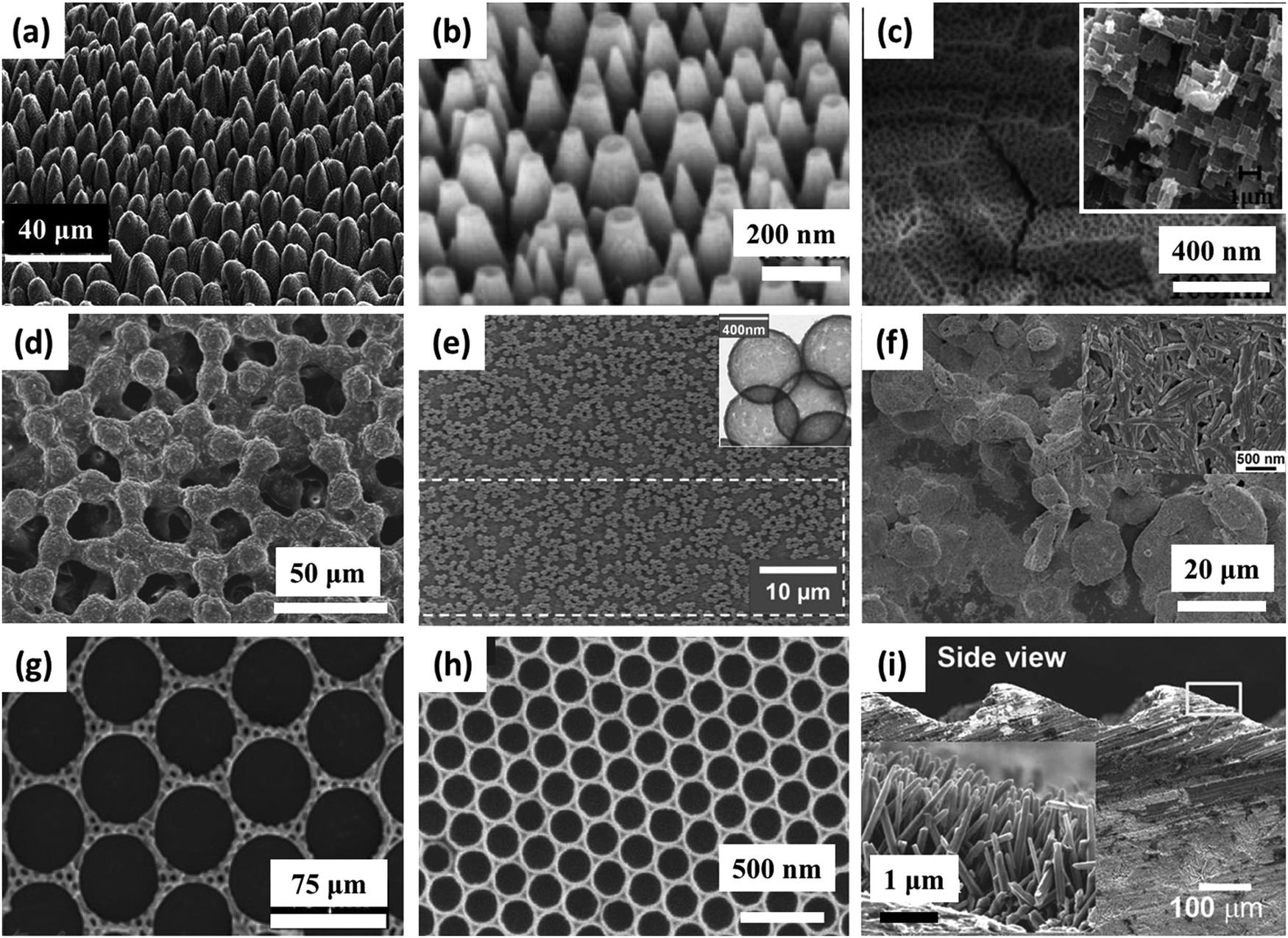 | ||
| Fig. 3 Examples of some surface textures investigated. First row, fabrication by top down methods: (a) micro scale structure fabricated by laser ablation,74 (b) glass surface with nanostructures after dry etching73 and (c) micro (inset) and nano structured Al surface by etching and anodizing.72 Second row fabrication by bottom up methods: (d) multilayer of spin-coated micro size PMMA spheres, crosslinked by silica,80 (e) glass slide with dip-coated silica nanoparticles sintered with silica bridges, inset shows the size of the individual hollow silica nanoparticles,81 and (f) hierarchical structure obtained from spray coated organosilane/attapulgite nanocomposite.55 Third row, fabrication by combined methods: (g) micro scale dual hole patterned CNT composite,88 (h) inverse monolayer nanostructure from colloidal assembly template and (i) machined steel surface with micro structures, inset shows ZnO nanohair grown on the surface.145 Figures reproduced from ref. 55, 72–74, 80, 81, 88 and 145 with permission from RSC, ACS, Springer, IOP, ACS, Wiley, Springer, and Wiley, respectively. | ||
 | ||
| Fig. 4 Representative compounds used in icephobic surface modification research. (a) (tridecafluoro-1,1,2,2,-tetrahydrooctyl)-trichlorosilane (FAS13-Cl), (b) (tridecafluoro-1,1,2,2,-tetrahydrooctyl)-triethoxysilane (POTS),92,94,96,97,101,102,104,109 (c) (heptadecafluoro-1,1,2,2-tetrahydrodecyl)-trichlorosilane (FAS17-1),80,106,124 (d) (heptadecafluoro-1,1,2,2-tetrahydrodecyl)-trimethoxysilane (FAS17-2),108,127 (e) (heptadecafluoro-1,1,2,2-tetrahydrodecyl)-triethoxysilane (FAS17-3),68,104,120,129,179 (f) (heptadecafluoro-1,1,2,2-tetrahydrodecyl)-triisopropoxysilane (FAS17-4),145 (g) (heptadecafluoro-1,1,2,2-tetrahydrodecyl)-dimethylchlorosilane (FAS17-5),76 (h) dodecafluoroheptyl-propyl-trimethoxysilane (FAS12),105,108 (i) 2-(perfluorooctyl) ethyl acrylate (F13-acrylate),123 (j) 2-(perfluorodecyl) ethyl acrylate (F17-acrylate),123 (k) tridecafluoro-1,1,2,2-tetrahydrooctylthiol (F13-thiol),79 (l) perfluorooctyl acid (C7F15-CO2H),93 (m) nonadecafluorodecanoic acid (C9F19-CO2H),180 (n) perfluorooctanesulfonic acid lithium salt (C8F17SO3Li),94 (o–q) alkyl-PO3H,181 (r) n-octadecyltrimethoxysilane (C18H37-silane),126 (s) n-octadecylthiol (C18H37-thiol),125 (t) n-octadecylamine (C18H37-amine),95 (u) n-tetradecyl acid (C13H27-CO2H),180 and (v) n-octadecyl acid (C17H35-CO2H).182–184 | ||
It is well recognized that multiscale micro/nano hierarchical structures typically offer superior performance. Barthwal et al.72 prepared hybrid structures on an aluminum substrate by employing chemical etching and aluminum surface anodization (Fig. 3c). Subsequent fluorination rendered the surface both superhydrophobic and superoleophobic. Tape adhesion tests (following the ASTM D3359-02 standard) were also carried out to quantify the mechanical stability of the as-prepared aluminum surface; the water and olive oil contact angles measured on these surfaces did not change after 10 repeated peel tests. Microhardness tests also showed that the micro/nano structured surface did not lose its superhydrophobicity or superoleophobicity after experiencing loads up to 80 kPa.
Similar approaches have been employed by Liao et al. to fabricate aluminum based superhydrophobic surfaces with micro/nanostructures.15 As previously noted (Table 1), these surfaces significantly delay ice nucleation and/or formation (by up to a factor of seven). Moreover, the surfaces maintain their superhydrophobicity after mechanical abrasion: (1) by water-drop impact, 5000 droplets; and (2) a sand impact test, 20 g, 210–350 μm in diameter, height up to 40 cm. Recent results from Wang et al.68 have shown that steel surfaces can also form micro/nanostructures by simple H2O2/acid etching treatment. The final fluorinated superhydrophobic surfaces maintain their superhydrophobicity after tape adhesion test (31.2 kPa) and sandpaper abrasion test (sandpaper as an abrading surface moved in one direction for 1.1 meter under 16 kPa gravity pressure). Moreover, water-dripping tests (with the substrate temperature held at −20 °C) demonstrated the ability for the superhydrophobic surfaces to quickly shed water droplets before freezing. A steam-freezing test (from 50 °C lowered to −20 °C at 90% humidity) further demonstrated the ability for the surfaces to reduce ice formation under very humid conditions.
Fig. 3d shows the microstructure of spin-coated poly(methyl methacrylate) (PMMA) microparticles covered with a crosslinked silica shell.80 After fluorination, the surface achieved superhydrophobicity with a static water contact angle of 167°. Lee et al.80 compared the hardness of the coating before and after silica crosslinking by employing a pencil hardness test (ASTM D3663). The electron irradiated (crosslinked) film passed a pencil hardness of 2H, indicating reasonable hardness of the film. In contrast, the pencil hardness of pristine PMMA/silicone grease film was substantially lower than 6B. Additional results from tape adhesion tests (ASTM D3359-02) and ultra-sonication confirmed the robustness of the surface after crosslinking.
A similar approach was adopted by Deng et al. to prepare transparent and mechanically-durable superhydrophobic surfaces using porous silica capsules (Fig. 3e).81 Chemical vapor deposition (CVD) of Tetraethyl orthosilicate (TEOS) in an environment of ammonia was employed to chemically crosslink dip-coated polystyrene (PS) nanoparticles. Superhydrophobicity was retained after a tape adhesion test (10 kPa) and a sand impacting test (sand size 100 to 300 μm, with an impact height of up to 30 cm).
Aside from fluorinated structures, long chain multifunctional organosilane (hexadecyltriethoxysilane) together with TEOS has also been employed to create crosslinked hybrid micro/nanostructures, as shown in Fig. 3f.55 The polymerized organosilane/attapulgite (a magnesium aluminium phyllosilicate) nanocomposite spray surface had a static contact angle of 161° and a sliding angle of 2°. Sand impact tests carried out using 100–300 μm sand grains at a height of 40 cm revealed that the surface can maintain its superhydrophobicity after undergoing sand tests with grain masses of 30 g or less (with static contact angle >150° and the sliding angle closes to 10°).
Instead of relying on a highly crosslinked silica network to enhance the mechanical durability, grafted and crosslinked polymer coatings showing durable anti-icing performances have been created in the Gleason group,59 using a versatile technique called initiated chemical vapor deposition (iCVD).37,82 Sojoudi et al.59 created divinyl benzene (DVB) and 1H, 1H, 2H, 2H-perfluorodecyl acrylate (PFDA) based smooth bilayer structures, with the crosslinked DVB network grafted directly to the silicon substrate. Repeated ice formation and ice removal steps did not alter the reduced ice adhesion strength measured on these fluoro-veneer surfaces. Furthermore, nanoscratch tests showed that the in situ grafting greatly reduced the possibility of coating delamination (Fig. 5a to d). Subsequent studies demonstrated that such grafted bilayer coatings can also significantly reduce the adhesion strength of clathrate hydrates, a subject related, but not identical, to icephobicity.83,84 It is worth noting that, this enhancement in the resistance to delamination as a result of direct surface grafting has been observed in multiple coatings created in the Gleason group.85,86 A passivation coating for silicon wafer constructed by iCVD deposited poly(ethylene glycol diacrylate) (pEGDA) with a grafted layer of 1,9-decadiene (DD) also exhibited no delamination during nanoscratch tests, whereas the same coating without the interstitial grafted layer showed serious delamination (Fig. 5e to h).86 Another grafted iCVD coating made of pPFDA-co-pDVB demonstrated excellent durability with no delamination during prolonged water vapor condensation tests carried out at 100 °C (Fig. 5i).85 In contrast, a fluorosilane-based grafted layer delaminated in only 30 min (Fig. 5j). Comparison of the heat transfer coefficient (HTC) vs. time for the different coatings further confirmed the durability of the grafted iCVD coating (Fig. 5k). In a separate study, a poly(trivinyltrimethylcyclotrisiloxane) based crosslinked iCVD coating demonstrated sustained electrical properties under physiological soak conditions for more than 2 years.87
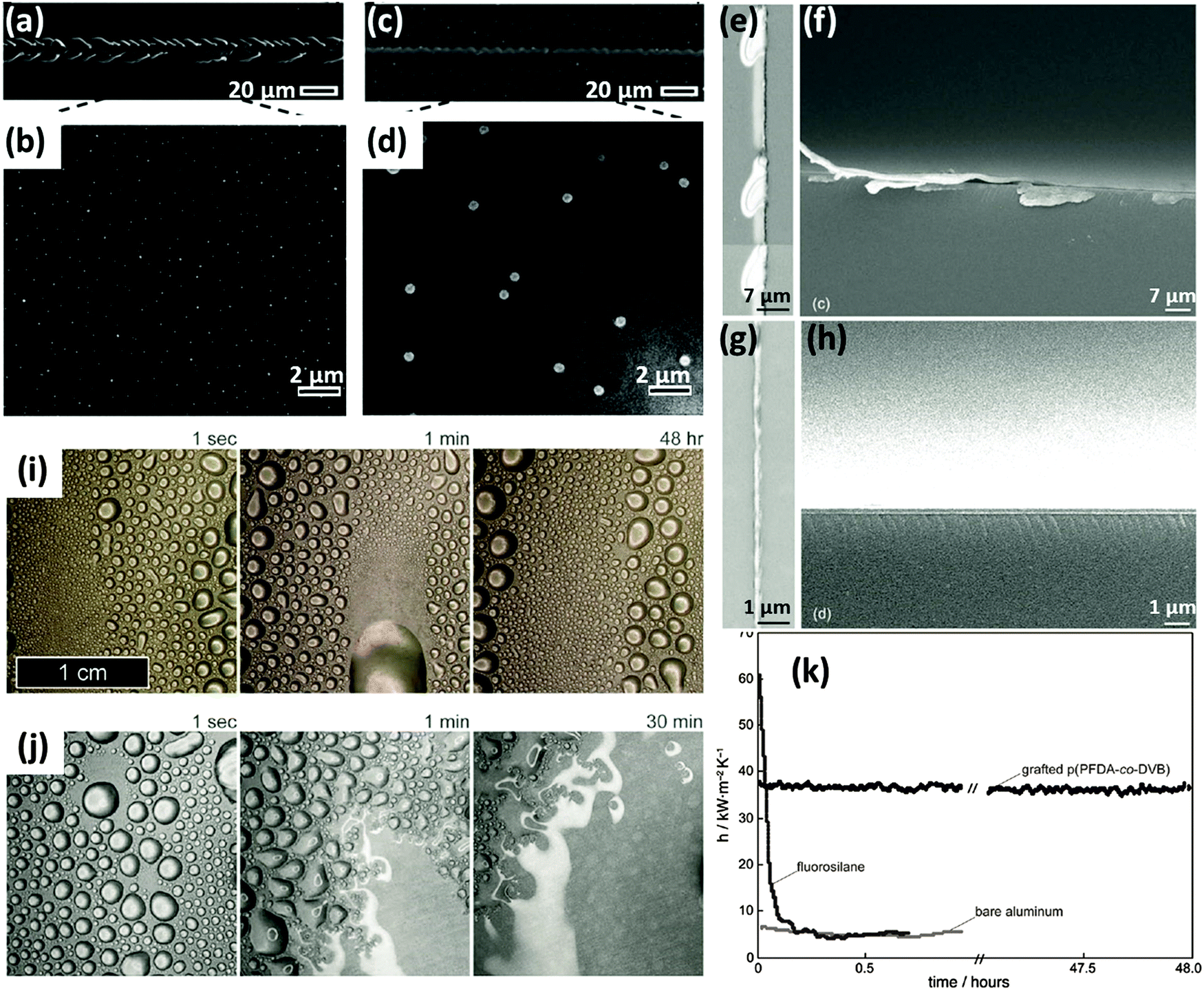 | ||
| Fig. 5 Enhanced durability of initiated chemical vapor deposited (iCVD) coatings by grafting. (a) and (b), SEM images of an ungrafted bilayer of poly (divinylbenzene)/poly(perfluorodecyl acrylate) (pDVB/pPFDA) showing delamination during nanoscratch tests,59 (c) and (d), SEM images of an grafted bilayer of pDVB/pPFDA showing no sign of delamination during nanoscratch tests;59 (e to h), iCVD deposited poly (ethylene glycol diacrylate) (pEGDA) with the grafted layer of 1,9-decadiene showing no delamination during nanoscratch tests (g, h), while same iCVD coating without grafted layer showing serious delamination (e, f);86 (i) prolonged dropwide condensation on grafted coating of pPFDA-co-DVB over a period of 48 h, at 100 °C, with no degradation,85 (j) grafted fluorosilane coating degraded over a period of 30 min,85 (k) heat transfer coefficient of aluminum substrates plotted vs. time, with no coating, with grafted iCVD coating, and grafted fluorosilane coating.85 Figures reproduced from ref. 59, 86 and 85 with the permissions from RSC, Wiley, and Wiley, respectively. | ||
Combined top-down and bottom-up methods have also been extended to hard steel surfaces (Fig. 3i) by: (1) machine abrading the steel surface to create robust microstructures; (2) zinc oxide nanohairs planting on top of the microstructures through adding seed crystals followed by synthesis inside a furnace; (3) fluorinating the micro/nanostructures. These surfaces retained their anti-icing properties after the ice formation/melting process was repeated for at least 20 times, indicating the durability of the surfaces. In a separate study, Boinovich et al.64 created durable superhydrophobic/icephobic surfaces by depositing hydrophobically-modified silicon nanoparticles on a chemically etched steel surfaces. It was found that the water contact angles and rolling angles for the superhydrophobic surfaces did not change after both tape adhesion test (130 kPa) and ultra-sonicating test (35 kHz, 55 W, 10 min). Furthermore, the surfaces maintained their superhydrophobicity after 100 ice formation/ice removal cycles.
3.2 Unique approaches toward damage-tolerant, protective or self-repairable superhydrophobic/icephobic surfaces
Three common characteristics shared by the aforementioned surface structures include: (1) the low surface energy materials and/or rough surface textures; (2) the surface topography is in direct contact with the imposed mechanical forces in the ice; (3) the icephobic surfaces fail once the surface chemistry and/or texture is damaged. As a result, a number of strategies aiming to solve these issues have been developed in the recent years.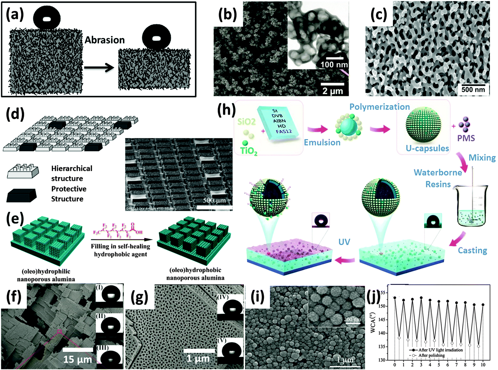 | ||
| Fig. 6 Representative strategies to enhance the durability of superhydrophobic/icephobic surfaces. (a) schematic illustration of a bulk material with low-surface-energy microstructures extending through its whole volume, sustains superhydrophobicity after mechanical abrasion;89 (b) candle soot template nanostructures, with fluorosilane (derived from tridecafluoro-1,1,2,2,-tetrahydrooctyl-trichlorosilane, FAS13-Cl) and nanostructures extended throughout the coating body;67 (c) silica rich glass nano structure from phase separation, with fluorosilane (derived from FAS13-Cl) and nanostructures extended throughout the coating body;90 (d) hierarchical micro and nano structures with protective pillars;91 (e), schematic depiction of filling a nanoporous alumina substrate with hydrophobic perfluorooctyl acid, (f) and (g) SEM images of anodized alumina with high density nanopores, representing the structure depicted in the scheme (e). (60% are pores, mean pore diameter is 40 nm and mean depth is 300 μm.) The insets are representative liquid droplets on perfluorooctyl acid loaded nanoporous alumina: (I) water, (II) glycerol, (III) CH2I2, (IV) hexadecane, (V) rapeseed oil;93 (h) schematics showing the procedure of fabricating UV responsive superhydrophobic coatings, (i) SEM images of UV responsive capsules before mixing with polysiloxane latex and (j) change of water contact angles as a function of repeated polishing and accelerated UV irradiation cycles.69 Figures reproduced from ref. 67, 69, 89–91, 93 with the permissions from Science, Wiley, RSC, IOP, ACS, and RSC, respectively. | ||
Deng et al.67 followed a different approach to create a fluorinated silica-based nanoporous structure (Fig. 6b). The candle soot was taken as the template followed by CVD deposition of TEOS in an ammonium vapor environment. Superamphiphobic character (i.e. strongly repellent towards both water and oil) was obtained after calcination and fluorination. The contact angles and sliding angles of both water and hexadecane droplets were almost identical before and after sand impacting test (using 20 g of 100–300 μm sands, at a height of 40 cm), although the silica shells were partially damaged by the process. The self-similarity of the fractal soot coating was deemed to be the major reason for maintaining the superamphiphobicity.
To further improve the robustness of such rough structures, Aytug et al. fabricated a nanostructured superhydrophobic surface from a spinodally phase-separated glass thin film (Fig. 6c).90 After fluorination, the monolithic nanoporous structure exhibited a static water contact angle of 163° and sliding angle of less than 5°. The surfaces were subjected to sand impact test (100 g of 100–300 μm highly abrasive Al2O3 particles at a height of 35 cm in 15 min) and simulated dust storm conditions (same amount of Al2O3 blasted at the same speed towards a superhydrophobic surface). The superhydrophobic performance of the surface was retained after these harsh tests.
As shown in Fig. 6e–g, Wang et al.93 used nanoporous anodized alumina to encapsulate the low surface energy chemical perfluorooctyl acid. The resulting surfaces exhibited superamphiphobicity towards both water and oils. Oxygen plasma treatment turned the superamphiphobic surfaces to superamphiphilic surfaces. However, the surfaces regained their superamphiphobicity after aging at room temperature for 48 h (or at 70 °C for 6 h). The release of the perfluorooctyl acid from nanopores and subsequent migration to the surface are the main driving forces behind this behavior. The surfaces were found to regain their superamphiphobicity after up to eight plasma treatment cycles. Aside from using nanoporous alumina as the reservoir, various structured materials have been selected to contain the low surface energy chemicals. Polyelectrolyte complex multilayers,92,94 polydopamine encapsulated mesoporous silica,95 electrochemically deposited porous poly(3,4-ethylenedioxythiophene) (PEDOT)96 and poly(urea-formaldehyde) capsules97 are some of the most recent choices and all of the resulting surfaces displayed self-repairing capabilities. The rate at which a plasma-damaged surface recovers its superhydrophobicity depends primarily on the temperature and humidity. In general, higher temperature and93 higher humidity92,95 allow a damaged surface to recover faster.
Specific trigger-based self-repairing surfaces have also been created. Chen et al.69 fabricated superhydrophobic coatings based on UV-responsive microcapsules (U-capsules) (Fig. 6h–j). The resulting surfaces were initially only hydrophobic, but turned superhydrophobic once irradiated by UV, and mechanically-damaged surface showed repeatable recovery of superhydrophobicity by UV irradiation (Fig. 6j). The UV responsive nature is based on the photocatalytic capability of TiO2 nanoparticles. The recovery time reported was at least 36 h, but the authors claimed that by carefully adjusting the TiO2/SiO2 ratio they could control the release speed under UV irradiation. Considering UV as a trigger might be beneficial for outdoor applications (e.g., anti-icing). In addition, instead of encapsulating the low surface energy chemicals inside the pores or capsules, Xue et al.98 embedded the polystyrene/SiO2 core–shell particles into a crosslinked hydrophobic PDMS network. The resulting superhydrophobic surfaces showed reasonable self-repairing performance. In addition to the expected thermal dependence, it was found that the recovery speed also depended on the self-repairing history of that surface (i.e., the number of cycles experienced). More cycles lead to a longer recovery time, indicating the PDMS chains needed longer time to re-arrange and move to the surface. The composite structure also displayed reasonable durability under the sand (300 to 1000 μm grains) impact tests from a height of 40 cm.
While all the aforementioned systems demonstrated self-repairing capabilities, one should realize that it usually takes days for a plasma- or mechanically-damaged superhydrophobic surface to recover, indicating that the self-repairing process is relatively slow.69,93,95 Although temperature and humidity can serve as external triggers to facilitate the process, these triggers might not be present in real applications, or might even be inimical (e.g. in anti-icing applications). A second concern is that the system will ultimately fail once the low surface energy chemicals depleted.93 In addition, it is desired to have mechanically durable self-repairing surfaces, but very limited mechanical durability characterizations have been reported.92,94,98 These practical concerns require further research.
3.3 Liquid infused surfaces for durable anti-icing applications
In Section 2.1 we have discussed the range of attributes that control the pagophobicity of engineered surfaces (hard vs. soft, dry vs. wet, smooth vs. rough). However, most of the pagophobic surfaces created to date possess hard, dry, and rough attributes.13,64,65,68 One can infer that in this category, the trapped air serves as the “lubricant” and reduces the contact area (and adhesion strength) between the water droplet and the underlying solid substrate. Hard, wet, and smooth icephobic surfaces have also been developed based on the liquid infused surface technology. As shown in Fig. 7a, Wong et al.38 fabricated slippery surfaces (SLIPS) by infusing textured surfaces with low surface energy liquids (3 M Fluorinert FC-70 or DuPont Krytox 100 and 103). These SLIPS surfaces demonstrated very small sliding angles towards both water and oils due to the presence of the lubricating liquid layer between the textured structure and the droplets. Further experiments from the same group revealed extreme anti-icing and anti-frosting performance of these slippery surfaces (Fig. 7b and c).25 The ice adhesion strength obtained on a SLIP coated aluminum surface was only ca. 1.2% of the one obtained on uncoated aluminum surface. Similar results were observed for lubricant-impregnated textured surfaces by Subramanyam et al.4 employing different approaches. In these studies, the liquid layer physically isolated the substrate texture from directly contacting the ice, and also prevented damage to the surface micro/nanostructures under action of the mechanical stresses during ice formation/ice removal cycles. In addition, the presence of low surface energy liquids inside the surface micro/nanostructure (which are retained due to the capillary force) help preventing frost/ice formation inside the nanoporous structures enhancing their performance, even under relatively high humid environment.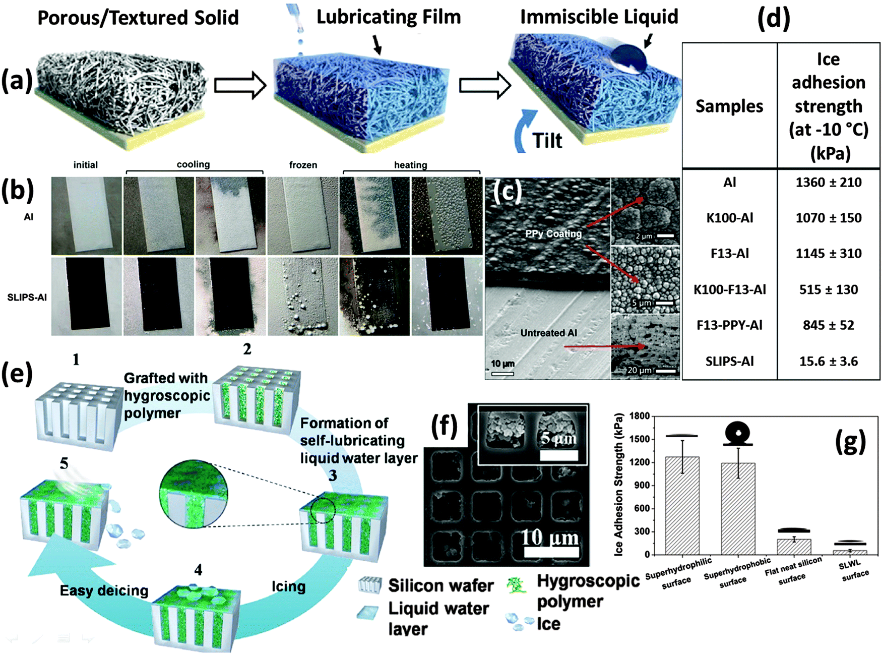 | ||
| Fig. 7 Liquid infused surfaces. (a) schematic showing the construction of a slippery liquid-infused porous surface (SLIPS),38 (b) the anti-ice performance of the SLIPS,25 (c) the structure of the SLIPS before liquid infusion,25 (d) the SLIPS on aluminum showed dramatic decrease in ice-adhesion strength.25 aluminum surface; K100-Al, perfluoroalkylether Krytox 100 (K100) lubricated aluminum surface; F13-Al, (tridecafluoro-1,1,2,2,-tetrahydrooctyl)-trichlorosilane (F13) treated aluminum surface; K100-F13-Al, Krytox 100 lubricated F13-Al; F13-PPY-Al, polypyrrole electrodeposition coated aluminum surface, treated with F13; SLIPS-Al, Krytox 100 lubricated F13-PPY-Al. (e) schematic showing the construction of aqueous liquid lubricated anti-ice surface,62 (f) SEM image of the structure depicted in scheme (e),62 (g) the ice adhesion strength is significantly reduced due to the self-lubricating effect.62 Figures reproduced from ref. 25, 38, 62 with the permission from ACS, NPG, and ACS, respectively. | ||
One concern over the performance of oil-based liquid infused surfaces is that the liquid will eventually be depleted by evaporation at elevated temperature or at reduced pressure, which can happen in outdoor conditions. To address this concern, Chen et al.62 created self-lubricating surfaces specifically for anti-icing applications (Fig. 7e–g). The lubrication was realized by employing hydrophilic polymers to lock a thin layer of water on the surface and act as the lubricant. Since the water can be supplied by ice continuously, there will be no concern over the depletion of the lubricant. The freezing point depression due to the interaction between hydrophilic polymer chains and the ice is the basis for the formation of the liquid water layer at a temperature well below 0 °C. The most recent results from the same group demonstrated maintenance of ice adhesion strength of ca. 27 kPa at temperatures down to ca. −53 °C.43 A second concern is the durability of the liquid lubricated surfaces upon mechanical contact, which can potentially damage the substrate and deplete the imbibed liquid and it is important to monitor the mechanical integrity of the surfaces.
3.4 Durability of superhydrophobic/icephobic surfaces toward UV irradiation
Another important concern not addressed yet is the durability of superhydrophobic/icephobic surfaces under UV irradiation, which is important in outdoor applications, because the high photon energy associated with UV light (e.g., solar UVA 320–400 nm, UVB 280 to 320 nm99) can potentially damage the organic materials contained in surface coatings and treatments.100 Inorganic nanoparticles/organic polymer based superhydrophobic structures are usually not stable under UV irradiation,89,101 because the presence of large quantities of organic components lead to oxidation and formation of hydrophilic groups.100 At the same time, photooxidative inorganic materials such as ZnO or TiO2 should also be avoided, since they can facilitate the degradation of the organic components.89,102–104 Most recent studies of superhydrophobic/icephobic surfaces with resistance to UV irradiation have been primarily based on inert inorganic micro/nano structures covered with perfluorosilanes,68,100,105 since inert fluorocarbon structures are generally more resistant to UV irradiation than hydrocarbons.68,100Fig. 8a and b show the durabilities of three types of superhydrophobic surface along with UV irradiation time (following ASTM D 4329).100 It is clear that the perfluorosilane treated inert silica demonstrated the best UV durability, isobutylsilane treated silica was less durable, and fluorinated polybutadiene was the most vulnerable film under action of UV irradiation. In addition, it is worth pointing out that the “U-capsule” based self-repairing system discussed above also displayed good durability toward UV irradiation (Fig. 8c and d); this is due to the excess perfluorosilane molecules constantly released from the capsules that help recover the superhydrophobicity. | ||
| Fig. 8 UV durability test. (a) Black curve, fluorinated polybutadiene superhydrophobic surface, red curve, isobutylsilane modified silica superhydrophobic surface, (isobutyltrimethoxysilane/tetramethoxysilane composite, IBTMOS-TMOS);100 (b) perfluorosilane covered silica superhydrophobic surface;100 (c)U-capsule based self-repairable superhydrophobic surface under accelerated weather condition (UV irradiation);69 (d) U-capsule based self-repairable superhydrophobic surface under outdoor exposure condition.69 (Insets are the water droplets on the coating panel after surfaces gained superhydrophobicity.) Figures reproduced from ref. 69 and 100 with permission from Wiley and Elsevier, respectively. | ||
It should be pointed out that the UV irradiation employed by most groups was in the UVA range,68,69,100–104,106,107 while the UVB range (with higher photon energies) has been less studied.89,105 To ensure that these superhydrophobic/icephobic surfaces can tolerate long term environmental UVB exposure, this spectral components should also be tested, since typical exposure conditions include both UVA and UVB ranges.99
3.5 Summary of techniques employed to quantify the surface durability
To better understand the durability of the aforementioned superhydrophobic/icephobic surfaces, a summary of most techniques are given in this section. It should be noted that, as a newly developed area, there are no standard procedures to quantify the durability of superhydrophobic/icephobic surfaces. Fig. 9 shows the most common characterization techniques employed to quantify mechanical and UV durability of superhydrophobic/icephobic surfaces, including UV irradiation (Fig. 9a),68,89,100–108 tape adhesion test (Fig. 9b),64,68,72 sand impact/abrasion test (Fig. 9c),89,92 ice formation/ice removal cycles (Fig. 9d),59 water jet/dripping test (Fig. 9e)15,68,109–112 and sandpaper abrasion test (Fig. 9f).89,92 A more complete summary of the common characterization techniques is listed in Table 3. In addition to the abovementioned tests, pencil hardness test,80,110,111,113–116 wipe test,73,106,117,118 ultra-sonication,64,80,107,119–122 solution/solvent immersion15,69,89,105–107,113,114,119,120,122–129 and thermal tests15,67,81,90,100,106,107,130 have also commonly been employed to characterize the durability of superhydrophobic/icephobic surfaces. As is apparent, most research groups have adopted individual and non-standardized conditions for their durability tests. Thus, care must be taken when judging and comparing the durability of the superhydrophobic/icephobic surfaces reported by different groups.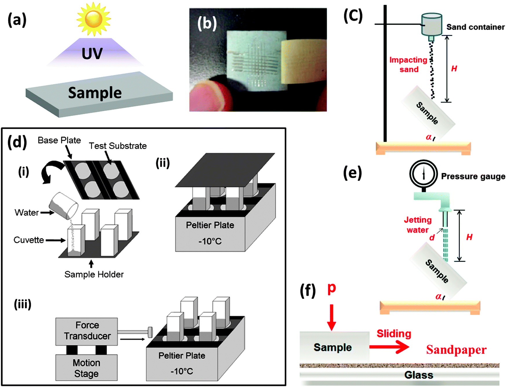 | ||
| Fig. 9 Common methods in use to quantify the durability of the superhydrophobic/icephobic surfaces. (a) UV irradiation, (b) tape adhesion test,127 (c) sand impact test,112 (d) ice formation/ice removal cycles3 (e) water jet/dripping test112 and (f) sandpaper abrasion measurement.112 Other common durability tests are immersion in salt solution or organic solvent, ultra-sonication, pencil hardness test, wipe test, and thermal treatment. (Not shown in the figure) Figures reproduced from ref. 3, 112 and 127 with permission from ACS, Elsevier, and ACS, respectively. | ||
| Techniques | Adopted non-standard operation conditions | Standards | Ref. |
|---|---|---|---|
| UV irradiation | Wavelength: typically 320 nm to 400 nm in the UVA range (e.g., 365 nm, 340 nm and 325 nm), but 254 nm (UVC) also used | ASTM D4329 | 68, 89, 100–108 |
| Intensity: several mW cm−2 to ca. 100 mW cm−2 | |||
| Irradiation time: several hours to thousands hours | |||
| Working temperature: room temperature to 60 °C | |||
| Tape adhesion test | Tapes: Scotch 810 Magic Tape, Scotch 600 tape | ASTM D3359-02, ASEM D3359-09, EN ISO 2409 | 64, 68, 72 |
| Applied pressure: typical pressure 10 kPa (up to 130 kPa) | |||
| Sandpaper abrasion test | Sandpaper grade: from M20 (14 to 20 μm in particle diameter) to 400 grit (ca. 35 μm in particle diameter) | N/A | 40, 68 |
| Applied pressure: typically 10 kPa or less (up to 20 kPa) | |||
| Speed: typically 5 cm s−1 or less (up to 20 cm s−1) | |||
| Distance: typically 1 m | |||
| Sand impacting/ abrasion test | Sand particle size: typically 100 to 300 μm | N/A | 15, 67, 81, 89, 90, 94, 98, 111, 112, 114, 117 |
| Height: typically 25 to 40 cm. Amount: typically 10 g to 100 g | |||
| Sample angle: 45 degree. Duration: typically 1 min to 15 min | |||
| Water jet/dripping test | Droplet size: 22 μL or 100 μL per drop | N/A | 15, 68, 109–112 |
| Height: 30 cm to 50 cm | |||
| Duration: 3 h to 90 h at a dripping speed of ca. 1 drop per s | |||
| Pencil hardness test | N/A | ASTM D3363ISO 15184 | 80, 110, 111, 113–116 |
| Wipe test | Wipe materials: fiber cloth or ITW texwipe TX 1112 | N/A | 73, 106, 117, 118 |
| Pressure: 4.5 kPa or 3.5 kPa | |||
| Ultra-sonication | Frequency: typically 35 kHz; Power: typically 55 W | N/A | 64, 80, 107, 119–122 |
| Time: 10 min to 14 h; Solvent: water or ethanol | |||
| Temperature: room temperature or 50 °C | |||
| Solution/solvent immersion test | Aqueous solutions: pure water, 3.5 wt% or 5 wt% NaCl in water, pH 0 to 14, 5.0 wt% KMnO4, hot or cold | N/A | 15, 69, 89, 105–107, 113, 114, 119, 120, 122–129 |
| Organic solvents: THF, DMF, ethanol, acetone, isopropanol, toluene, hexane and CHCl3 | |||
| Ice formation/ice removal | By mechanical removal, or by melting | N/A | 59 |
| Thermal test | Environment: air | N/A | 15, 67, 81, 90, 100, 106, 107, 130 |
| Temperature: superhydrophobicity sustained up to ca. 400 °C |
4 Approaches towards preparation of robust and scalable superhydrophobic/pagophobic surfaces
The previous sections have highlighted the multiplicity of distinct behaviors that are described as icephobicity in the literature and reported the proposed routes towards the preparation of durable superhydrophobic and/or pagophobic surfaces. The present section focuses on a discussion of the most scalable approaches towards the formation of durable superhydrophobic and/or icephobic surfaces. The first subsection reports various subtractive approaches towards the preparation of robust microstructures and/or nanostructures on large scale substrates. As discussed previously, a patterned rough topography is not appropriate for all kinds of pagophobicity and has been reported to increase the ice adhesion strength when frost formation occurs in high humidity test environments. Under these conditions, smooth surfaces will be preferred. The second subsection, focuses on hydrophobization of both smooth and rough surfaces by an up-scalable chemical vapor deposition method.4.1 Subtractive approaches towards the preparation of robust microstructures and/or nanostructures on large scale substrates
Among the different routes reported for the preparation of micro- and/or nano-structured surfaces, subtractive approaches can lead to the formation of robust features which are monolithic to the substrate. A number of subtractive methods have been developed for imparting texture to various surfaces to confer on them superhydrophobic and/or icephobic properties, e.g. laser ablation131 or plasma etching.132 Some of the developed processes are particularly suitable for texturing large scale surfaces. | ||
| Fig. 10 Schematic diagrams of roll-to-roll (a) chemical etching, (b) sandblasting or abrasive etching and (c) mechanical machining processes. SEM images of the resulting microstructured topographies of icephobic surfaces prepared by (d) chemical etching of stainless steel using FeCl3 for preventing snow accumulation64 (e) sand-blasting of titanium alloy for delayed icing, reduction of ice adhesion strength, and bouncing of supercooled water droplets144 and (f) mechanical machining of stainless steel for delayed icing and bouncing of supercooled water droplets.145 Figures reproduced from ref. 64, 144 and 145 with permission from ACS, RSC, and Wiley, respectively. | ||
Electrochemical etching for durations in excess of one hour in H2SO4, C2H2O4 and C3H8O3 solution8 for aluminum or in H3PO4 for aluminum135 and brass136,137 have also been reported to produce robust structures that give rise to pagophobic properties after their hydrophobization. Silicon has also been electrochemically etched in solution of AgNO3 and HF to form densely distributed vertical silicon pillars that led to superhydrophobicity after hydrophobization.138
The chemical etching approach is not specific to metals and has also been impressively transposed to textiles in order to make them superhydrophobic.15 Poly(ethylene terephthalate) (PET) textiles dipped for 10 minutes in a NaOH solution did exhibit WCA above 160° after hydrophobization. Interestingly, superhydrophobicity was retained even after the conventional transfer printing step used to color the textiles. More importantly, the superhydrophobicity was not affected by subsequent laundering and UV-irradiation. Severe abrasion tests using a friction instrument for textiles,139 even when leading to the rupture of several textile fibers, barely influenced the WCA. However, after 500 abrasion cycles, the change of the WCA and CAH to 60° and 25°, respectively, indicated a progressive switch from a Cassie–Baxter state to Wenzel-state.140
Another common industrial process through which the targeted surface topography can be directly produced during the forming step is the electrospinning of fabrics. Ma et al. have prepared poly(caprolactone) (PCL) mats with the desired morphology by selecting an appropriate polymeric fluid composition and operating parameters during electrospinning.157 The inherent surface roughness of the PCL electrospun mats coated with a low surface energy polymer produce stable superhydrophobic nonwoven fabrics with WCA as high as 175°.
4.2 iCVD hydrophobization of smooth and rough surfaces
Unless the substrate materials that are deposited or patterned intrinsically possess a hydrophobic chemistry (e.g. laminated PE), hydrophobization is a subsequent process that is required, and it can be achieved by many different methods.158,159 Among them, chemical vapor deposition (CVD) methods provide all-dry and up-scalable routes for the deposition of both smooth or nanostructured low surface energy materials. Most of the CVD methods, e.g. atmospheric41,160 and low-pressure161 CVD involving vapors or aerosol162 of the monomer compounds and possibly assisted by plasma,135,138,153,155 flame163 or hot filaments,59,164 have been successfully investigated for the hydrophobization of various substrate materials. However, the present section will solely focus on the initiated CVD (iCVD) approach that is compatible with roll-to-roll processes165 and fabrication of large scale surfaces.37iCVD is a free-radical polymerization method that, similarly to solution-based approaches, begins with the decomposition of an initiator agent into radical species.37 In iCVD, the initiator’s labile bond, e.g. the O–O bond in peroxides, is thermally cleaved in the gas phase thanks to heating filaments. The most common initiators used in iCVD include tert-butyl peroxide (TBPO),166tert-butyl peroxybenzoate (TBPOB),167tert-amyl peroxide (TAPO),168 perfluoro-1-butanesulfonyl fluoride (PBSF)169,170 and perfluorooctanesulfonyl fluoride (PFOS).171 The radicals formed subsequently initiate chain-growth polymerization of the monomers adsorbed at the surface of the substrate. Among the large number of monomers investigated, perfluorodecylacrylate (PFDA),166,172–174 heptadecafluorodecylmethacrylate (HFDMA),175 perfluoroalkylethylmethacrylate (PFEMA)157 and hexafluoropropylene oxide (HFPO)169,170 are particularly important for development of low surface energy polymers.
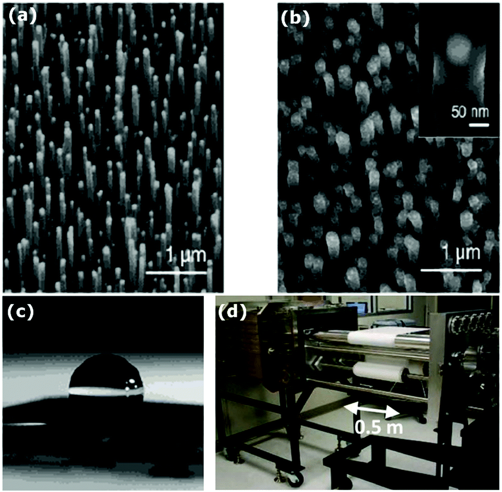 | ||
| Fig. 11 SEM images of (a) as as-grown carbon nanotube forest, (b) a carbon nanotube forest conformally coated by a 50 nm thick PTFE layer deposited by iCVD, and (c) a spherical water droplet on the PTFE-coated carbon nanotube forest.169 (d) Schematic of a roll-to-roll iCVD system for the hydrophobization of large scale substrates. Figures are reproduced from ref. 169 with permission from ACS. | ||
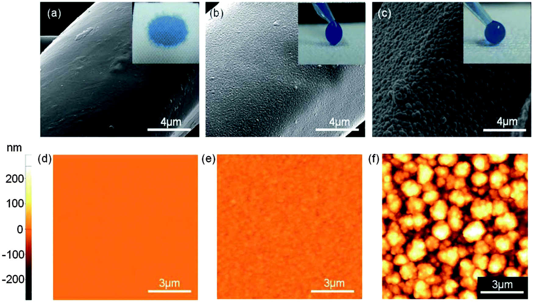 | ||
| Fig. 12 SEM and AFM images of (a & d) a non-coated polyester fabric surface, (b & e) a slightly rough PV4D4/PPFDA stacked polymers iCVD-coated fabric surface and (c & f) a rougher surface of the PV4D4/PPFDA stacked polymer iCVD-coated fabric surface. Inset images show water droplets on the respective surfaces.174 Figures are reproduced from ref. 174 with permission from RSC. | ||
000 abrasion cycles and 75 laundry cycles.
The bilayer approach employed by Sojoudi et al. has built on these studies to develop durable surfaces for ice adhesion reduction.59 In the first step of their iCVD process, radicals were formed on the surface of the substrate in order to provide anchoring points for a divinyl benzene (DVB) monomer that covalently binds to the substrate. The highly crosslinked poly(divinyl benzene) (PDVB) layer exhibits pendant vinyl groups to which a second layer made of PPFDA covalently bonded. The benefit of such an approach was highlighted by nanomechanical measurements that revealed an enhancement in both the elastic modulus and the hardness of the films composed of the bilayer structure. In addition, the grafted bilayer coatings did not undergo delamination upon scratching. Finally, the strength of ice adhesion to the substrates was reduced more than six-fold when coated with PDVB/PPFDA grafted layers, highlighting the potential of iCVD for pagophobic applications.
5 Conclusions
Many operability, durability, and scalability challenges need to be addressed in order to enable the practical use of pagophobic coatings. Icephobic surfaces must perform well in various operating conditions including high humidity, very low temperatures, high velocity, severe mechanical/chemical/radiation conditions, and during impact with high speed water droplets. Ice formation mechanisms vary widely and the differing constraints of each mode must be factored in while designing and characterizing various coatings. We have categorized and critically discussed recent development on pagophobic surfaces highlighting those which have also shown promise in their durability and scalability. Additional design challenges for icephobic materials include preservation of the initial characteristics in terms of surface hydrophobicity, despite prolonged exposure to severe wear mechanisms such as erosion and corrosion. In addition for aeronautic and wind turbine applications, the surfaces must also be tested in a realistic and dynamic environment such as inside an icing tunnel at high enough velocities, analogous to the conditions encountered during operation.Acknowledgements
This work was supported by Kuwait-MIT Center for Natural Resources and the Environment (CNRE), which was funded by Kuwait Foundation for the Advancement of Sciences (KFAS). The authors acknowledge support from the MIT-Chevron university partnership program. This work was partially supported by the MIT Institute for Solider Nanotechnologies under Contract DAAD-19-02D-002 with the U.S. Army Research Office. NDB is particularly grateful to the “Fonds National de la Recherche” (FNR) of Luxembourg for supporting his visiting scientist position within the Gleason group (SENSi project).Notes and references
- S. A. Kulinich and M. Farzaneh, Langmuir, 2009, 25, 8854–8856 CrossRef CAS PubMed.
- S. A. Kulinich and M. Farzaneh, Appl. Surf. Sci., 2009, 255, 8153–8157 CrossRef CAS.
- A. J. Meuler, J. D. Smith, K. K. Varanasi, J. M. Mabry, G. H. McKinley and R. E. Cohen, ACS Appl. Mater. Interfaces, 2010, 2, 3100–3110 CAS.
- S. B. Subramanyam, K. Rykaczewski and K. K. Varanasi, Langmuir, 2013, 29, 13414–13418 CrossRef CAS PubMed.
- K. K. Varanasi, T. Deng, J. D. Smith, M. Hsu and N. Bhate, Appl. Phys. Lett., 2010, 97, 234102 CrossRef.
- L. Makkonen, J. Adhes. Sci. Technol., 2012, 26, 413–445 CAS.
- Q. Fu, X. Wu, D. Kumar, J. W. C. Ho, P. D. Kanhere, N. Srikanth, E. Liu, P. Wilson and Z. Chen, ACS Appl. Mater. Interfaces, 2014, 6, 20685–20692 CAS.
- M. Ruan, W. Li, B. Wang, B. Deng, F. Ma and Z. Yu, Langmuir, 2013, 29, 8482–8491 CrossRef CAS PubMed.
- D. K. Sarkar and M. Farzaneh, J. Adhes. Sci. Technol., 2009, 23, 1215–1237 CrossRef CAS.
- J. Lv, Y. Song, L. Jiang and J. Wang, ACS Nano, 2014, 8, 3152–3169 CrossRef CAS PubMed.
- Y. Wang, J. Xue, Q. Wang, Q. Chen and J. Ding, ACS Appl. Mater. Interfaces, 2013, 5, 3370–3381 CAS.
- P. Tourkine, M. Le Merrer and D. Quere, Langmuir, 2009, 25, 7214–7216 CrossRef CAS PubMed.
- L. Cao, A. K. Jones, V. K. Sikka, J. Wu and D. Gao, Langmuir, 2009, 25, 12444–12448 CrossRef CAS PubMed.
- S. Jung, M. Dorrestijn, D. Raps, A. Das, C. M. Megaridis and D. Poulikakos, Langmuir, 2011, 27, 3059–3066 CrossRef CAS PubMed.
- R. Liao, Z. Zuo, C. Guo, Y. Yuan and A. Zhuang, Appl. Surf. Sci., 2014, 317, 701–709 CrossRef CAS.
- M. Susoff, K. Siegmann, C. Pfaffenroth and M. Hirayama, Appl. Surf. Sci., 2013, 282, 870–879 CrossRef CAS.
- H. Wang, G. He and Q. Tian, Appl. Surf. Sci., 2012, 258, 7219–7224 CrossRef CAS.
- S. Yang, Q. Xia, L. Zhu, J. Xue, Q. Wang and Q.-m. Chen, Appl. Surf. Sci., 2011, 257, 4956–4962 CrossRef CAS.
- V. Hejazi, K. Sobolev and M. Nosonovsky, Sci. Rep., 2013, 3, 1–6 Search PubMed.
- X. Sun, V. G. Damle, S. Liu and K. Rykaczewski, Adv. Mater. Interfaces, 2015, 2, 1400479 Search PubMed.
- S. Frankenstein and A. M. Tuthill, J. Cold Reg. Eng., 2002, 16, 83–96 CrossRef.
- R. M. Fillion, A. R. Riahi and A. Edrisy, Renewable Sustainable Energy Rev., 2014, 32, 797–809 CrossRef CAS.
- O. Parent and A. Ilinca, Cold Reg. Sci. Technol., 2011, 65, 88–96 CrossRef.
- S. Farhadi, M. Farzaneh and S. A. Kulinich, Appl. Surf. Sci., 2011, 257, 6264–6269 CrossRef CAS.
- P. Kim, T. S. Wong, J. Alvarenga, M. J. Kreder, W. E. Adorno-Martinez and J. Aizenberg, ACS Nano, 2012, 6, 6569–6577 CrossRef CAS PubMed.
- P. W. Wilson, W. Lu, H. Xu, P. Kim, M. J. Kreder, J. Alvarenga and J. Aizenberg, Phys. Chem. Chem. Phys., 2013, 15, 581–585 RSC.
- H. A. Stone, ACS Nano, 2012, 6, 6536–6540 CrossRef CAS PubMed.
- C. R. Watson, R. C. Dolan, J. W. Putnam, B. B. Bonarrigo, P. L. Kurz and M. A. Weisse, Erosion resistant anti-icing coatings, European Patent Office EP1849843 A1, 2007 Search PubMed.
- X. H. Li, Y. H. Zhao, H. Li and X. Y. Yuan, Appl. Surf. Sci., 2014, 316, 222–231 CrossRef CAS.
- L. Zhu, J. Xue, Y. Wang, Q. Chen, J. Ding and Q. Wang, ACS Appl. Mater. Interfaces, 2013, 5, 4053–4062 Search PubMed.
- L. Mishchenko, B. Hatton, V. Bahadur, J. A. Taylor, T. Krupenkin and J. Aizenberg, ACS Nano, 2010, 4, 7699–7707 CrossRef PubMed.
- A. Alizadeh, M. Yamada, R. Li, W. Shang, S. Otta, S. Zhong, L. Ge, A. Dhinojwala, K. R. Conway, V. Bahadur, A. J. Vinciquerra, B. Stephens and M. L. Blohm, Langmuir, 2012, 28, 3180–3186 CrossRef PubMed.
- H. Saito, K. Takai, H. Takazawa and G. Yamauchi, Mater. Sci. Res. Int., 1997, 3, 216–219 CAS.
- J. Chen, J. Liu, M. He, K. Li, D. Cui, Q. Zhang, X. Zeng, Y. Zhang, J. Wang and Y. Song, Appl. Phys. Lett., 2012, 101, 111603 CrossRef.
- A. Alizadeh, V. Bahadur, A. Kulkarni, M. Yamada and J. A. Ruud, MRS Bull., 2013, 38, 407–411 CrossRef.
- T. M. Schutzius, S. Jung, T. Maitra, P. Eberle, C. Antonini, C. Stamatopoulos and D. Poulikakos, Langmuir, 2014, 31, 4807–4821 CrossRef PubMed.
- A. M. Coclite, R. M. Howden, D. C. Borrelli, C. D. Petruczok, R. Yang, J. L. Yague, A. Ugur, N. Chen, S. Lee, W. J. Jo, A. D. Liu, X. X. Wang and K. K. Gleason, Adv. Mater., 2013, 25, 5392–5422 CrossRef PubMed.
- T. S. Wong, S. H. Kang, S. K. Y. Tang, E. J. Smythe, B. D. Hatton, A. Grinthal and J. Aizenberg, Nature, 2011, 477, 443–447 CrossRef CAS PubMed.
- J. D. Smith, R. Dhiman, S. Anand, E. Reza-Garduno, R. E. Cohen, G. H. McKinley and K. K. Varanasi, Soft Matter, 2013, 9, 1772–1780 RSC.
- N. Vogel, R. A. Belisle, B. Hatton, T.-S. Wong and J. Aizenberg, Nat. Commun., 2013, 4, 2176 Search PubMed.
- C. R. Crick, S. Ismail, J. Pratten and I. P. Parkin, Thin Solid Films, 2011, 519, 3722–3727 CrossRef CAS.
- F. Arianpour, M. Farzaneh and S. A. Kulinich, Appl. Surf. Sci., 2013, 265, 546–552 CrossRef CAS.
- R. M. Dou, J. Chen, Y. F. Zhang, X. P. Wang, D. P. Cui, Y. L. Song, L. Jiang and J. J. Wang, ACS Appl. Mater. Interfaces, 2014, 6, 6998–7003 CAS.
- A. B. D. Cassie and S. Baxter, Trans. Faraday Soc., 1944, 40, 0546–0550 RSC.
- L. C. Gao and T. J. McCarthy, Langmuir, 2009, 25, 14105–14115 CrossRef CAS PubMed.
- A. Marmur, Langmuir, 2003, 19, 8343–8348 CrossRef CAS.
- A. J. Meuler, G. H. McKinley and R. E. Cohen, ACS Nano, 2010, 4, 7048–7052 CrossRef CAS PubMed.
- C. Antonini, M. Innocenti, T. Horn, M. Marengo and A. Amirfazli, Cold Reg. Sci. Technol., 2011, 67, 58–67 CrossRef.
- P. Eberle, M. K. Tiwari, T. Maitra and D. Poulikakos, Nanoscale, 2014, 6, 4874–4881 RSC.
- T. Maitra, M. K. Tiwari, C. Antonini, P. Schoch, S. Jung, P. Eberle and D. Poulikakos, Nano Lett., 2014, 14, 172–182 CrossRef CAS PubMed.
- J. C. Bird, R. Dhiman, H.-M. Kwon and K. K. Varanasi, Nature, 2013, 503, 385 CrossRef CAS PubMed.
- T. Furuta, M. Sakai, T. Isobe and A. Nakajima, Langmuir, 2010, 26, 13305–13309 CrossRef CAS PubMed.
- Z. Liu, Y. Gou, J. Wang and S. Cheng, Int. J. Heat Mass Transfer, 2008, 51, 5975–5982 CrossRef.
- L. Cai, R. Wang, P. Hou and X. Zhang, Energy Build., 2011, 43, 1159–1163 CrossRef.
- Q. Zhang, M. He, J. Chen, J. Wang, Y. Song and L. Jiang, Chem. Commun., 2013, 49, 4516–4518 RSC.
- Q. Zhang, M. He, X. Zeng, K. Li, D. Cui, J. Chen, J. Wang, Y. Song and L. Jiang, Soft Matter, 2012, 8, 8285–8288 RSC.
- R. Menini and M. Farzaneh, J. Adhes. Sci. Technol., 2011, 25, 971–992 Search PubMed.
- Y. Li and G. A. Somorjai, J. Phys. Chem. C, 2007, 111, 9631–9637 CAS.
- H. Sojoudi, G. H. McKinley and K. K. Gleason, Mater. Horiz., 2015, 2, 91–99 RSC.
- L. C. Gao and T. J. McCarthy, Langmuir, 2008, 24, 9183–9188 CrossRef CAS PubMed.
- M. Nosonovsky and V. Hejazi, ACS Nano, 2012, 6, 8488–8491 CrossRef CAS PubMed.
- J. Chen, R. Dou, D. Cui, Q. Zhang, Y. Zhang, F. Xu, X. Zhou, J. Wang, Y. Song and L. Jiang, ACS Appl. Mater. Interfaces, 2013, 5, 4026–4030 CAS.
- A. Nakajima, J. Ceram. Soc. Jpn., 2004, 112, 533–540 CrossRef CAS.
- L. B. Boinovich, A. M. Emelyanenko, V. K. Ivanov and A. S. Pashinin, ACS Appl. Mater. Interfaces, 2013, 5, 2549–2554 CAS.
- J. Y. Lv, Y. L. Song, L. Jiang and J. J. Wang, ACS Nano, 2014, 8, 3152–3169 CrossRef CAS PubMed.
- C.-H. Xue and J.-Z. Ma, J. Mater. Chem. A, 2013, 1, 4146–4161 CAS.
- X. Deng, L. Mammen, H.-J. Butt and D. Vollmer, Science, 2012, 335, 67–70 CrossRef CAS PubMed.
- N. Wang, D. Xiong, Y. Deng, Y. Shi and K. Wang, ACS Appl. Mater. Interfaces, 2015, 7, 6260–6272 CAS.
- K. Chen, S. Zhou, S. Yang and L. Wu, Adv. Funct. Mater., 2015, 25, 1035–1041 CrossRef CAS.
- R. Haywood, Photochem. Photobiol., 2006, 82, 1123–1131 CrossRef CAS PubMed.
- L. Li, V. Breedveld and D. W. Hess, ACS Appl. Mater. Interfaces, 2012, 4, 4549–4556 Search PubMed.
- S. Barthwal, Y. S. Kim and S.-H. Lim, Langmuir, 2013, 29, 11966–11974 CrossRef CAS PubMed.
- D. Infante, K. W. Koch, P. Mazumder, L. Tian, A. Carrilero, D. Tulli, D. Baker and V. Pruneri, Nano Res., 2013, 6, 429–440 CrossRef CAS.
- A. Steele, B. K. Nayak, A. Davis, M. C. Gupta and E. Loth, J. Micromech. Microeng., 2013, 23, 115012 CrossRef.
- A. Y. Vorobyev and C. L. Guo, J. Appl. Phys., 2015, 117, 033103 Search PubMed.
- D. T. Ge, L. L. Yang, G. X. Wu and S. Yang, Chem. Commun., 2014, 50, 2469–2472 RSC.
- Y. Liao, C.-H. Loh, R. Wang and A. G. Fane, ACS Appl. Mater. Interfaces, 2014, 6, 16035–16048 CAS.
- I. Yilgor, S. Bilgin, M. Isik and E. Yilgor, Polymer, 2012, 53, 1180–1188 CrossRef CAS.
- S. Amigoni, E. T. de Givenchy, M. Dufay and F. Guittard, Langmuir, 2009, 25, 11073–11077 CrossRef CAS PubMed.
- E. J. Lee, J. J. Kim and S. O. Cho, Langmuir, 2010, 26, 3024–3030 CrossRef CAS PubMed.
- X. Deng, L. Mammen, Y. F. Zhao, P. Lellig, K. Mullen, C. Li, H. J. Butt and D. Vollmer, Adv. Mater., 2011, 23, 2962 CrossRef CAS PubMed.
- R. Yang, E. Goktekin, M. H. Wang and K. K. Gleason, J. Biomater. Sci., Polym. Ed., 2014, 25, 1687–1702 CrossRef CAS PubMed.
- H. Sojoudi, M. R. Walsh, K. K. Gleason and G. H. McKinley, Adv. Mater. Interfaces, 2015, 2, 1500003 Search PubMed.
- H. Sojoudi, M. R. Walsh, K. K. Gleason and G. H. McKinley, Langmuir, 2015, 31, 6186–6196 CrossRef CAS PubMed.
- A. T. Paxson, J. L. Yagüe, K. K. Gleason and K. K. Varanasi, Adv. Mater., 2014, 26, 418–423 CrossRef CAS PubMed.
- R. Yang, T. Buonassisi and K. K. Gleason, Adv. Mater., 2013, 25, 2078–2083 CrossRef CAS PubMed.
- W. S. O'Shaughnessy, S. K. Murthy, D. J. Edell and K. K. Gleason, Biomacromolecules, 2007, 8, 2564–2570 CrossRef PubMed.
- S.-H. Park, E.-H. Cho, J. Sohn, P. Theilmann, K. Chu, S. Lee, Y. Sohn, D. Kim and B. Kim, Nano Res., 2013, 6, 389–398 CrossRef CAS.
- X. Zhang, Y. G. Guo, H. Z. Chen, W. Z. Zhu and P. Y. Zhang, J. Mater. Chem. A, 2014, 2, 9002–9006 CAS.
- T. Aytug, J. T. Simpson, A. R. Lupini, R. M. Trejo, G. E. Jellison, I. N. Ivanov, S. J. Pennycook, D. A. Hillesheim, K. O. Winter, D. K. Christen, S. R. Hunter and J. A. Haynes, Nanotechnology, 2013, 24, 315602 CrossRef PubMed.
- E. Huovinen, L. Takkunen, T. Korpela, M. Suvanto, T. T. Pakkanen and T. A. Pakkanen, Langmuir, 2014, 30, 1435–1443 CrossRef CAS PubMed.
- Y. Li, L. Li and J. Sun, Angew. Chem., Int. Ed., 2010, 49, 6129–6133 CrossRef CAS PubMed.
- X. Wang, X. Liu, F. Zhou and W. Liu, Chem. Commun., 2011, 47, 2324–2326 RSC.
- Y. Li, S. Chen, M. Wu and J. Sun, Adv. Mater., 2014, 26, 3344–3348 CrossRef CAS PubMed.
- Q. Z. Liu, X. L. Wang, B. Yu, F. Zhou and Q. J. Xue, Langmuir, 2012, 28, 5845–5849 CrossRef CAS PubMed.
- D. Zhu, X. Lu and Q. Lu, Langmuir, 2014, 30, 4671–4677 CrossRef CAS PubMed.
- G. Wu, J. An, X.-Z. Tang, Y. Xiang and J. Yang, Adv. Funct. Mater., 2014, 24, 6751–6761 CrossRef CAS.
- C.-H. Xue, Z.-D. Zhang, J. Zhang and S.-T. Jia, J. Mater. Chem. A, 2014, 2, 15001–15007 CAS.
- F. R. Degruijl, H. Sterenborg, P. D. Forbes, R. E. Davies, C. Cole, G. Kelfkens, H. Vanweelden, H. Slaper and J. C. Vanderleun, Cancer Res., 1993, 53, 53–60 CAS.
- Y. H. Xiu, D. W. Hess and C. R. Wong, J. Colloid Interface Sci., 2008, 326, 465–470 CrossRef PubMed.
- T. Nahum, H. Dodiuk, A. Dotan, S. Kenig and J. P. Lellouche, J. Appl. Polym. Sci., 2014, 131, 41122 CrossRef.
- Z. Sun, T. Liao, K. Liu, L. Jiang, J. H. Kim and S. X. Dou, Nano Res., 2013, 6, 726–735 CrossRef CAS.
- L. Wang, X. Zhang, Y. Fu, B. Li and Y. Liu, Langmuir, 2009, 25, 13619–13624 CrossRef CAS PubMed.
- Y. Q. Gao, I. Gereige, A. El Labban, D. Cha, T. T. Isimjan and P. M. Beaujuge, ACS Appl. Mater. Interfaces, 2014, 6, 2219–2223 CAS.
- L. J. Li, T. Huang, J. L. Lei, J. X. He, L. F. Qu, P. L. Huang, W. Zhou, N. B. Li and F. S. Pan, ACS Appl. Mater. Interfaces, 2015, 7, 1449–1457 CAS.
- S. Hoshian, V. Jokinen, V. Somerkivi, A. R. Lokanathan and S. Franssila, ACS Appl. Mater. Interfaces, 2015, 7, 941–949 CAS.
- F. J. Wang, C. Q. Li, Z. S. Tan, W. Li, J. F. Ou and M. S. Xue, Surf. Coat. Technol., 2013, 222, 55–61 CrossRef CAS.
- K. L. Chen, S. X. Zhou, S. Yang and L. M. Wu, Adv. Funct. Mater., 2015, 25, 1035–1041 CrossRef CAS.
- A. Yildirim, H. Budunoglu, B. Daglar, H. Deniz and M. Bayindir, ACS Appl. Mater. Interfaces, 2011, 3, 1804–1808 CAS.
- H. Budunoglu, A. Yildirim and M. Bayindir, J. Mater. Chem., 2012, 22, 9671–9677 RSC.
- Z. Geng and J. H. He, J. Mater. Chem. A, 2014, 2, 16601–16607 CAS.
- Y. Zhang, D. Ge and S. Yang, J. Colloid Interface Sci., 2014, 423, 101–107 CrossRef CAS PubMed.
- S. M. Lee, K. S. Kim, E. Pippel, S. Kim, J. H. Kim and H. J. Lee, J. Phys. Chem. C, 2012, 116, 2781–2790 CAS.
- L. G. Xu, Z. Geng, J. H. He and G. Zhou, ACS Appl. Mater. Interfaces, 2014, 6, 9029–9035 CAS.
- R. V. Lakshmi, T. Bharathidasan and B. J. Basu, Appl. Surf. Sci., 2011, 257, 10421–10426 CrossRef CAS.
- S. A. Seyedmehdi, H. Zhang and J. Zhu, J. Appl. Polym. Sci., 2013, 128, 4136–4140 CrossRef CAS.
- Y. H. Xiu, Y. Liu, D. W. Hess and C. P. Wong, Nanotechnology, 2010, 21, 155705 CrossRef PubMed.
- P. Mazumder, Y. Jiang, D. Baker, A. Carrilero, D. Tulli, D. Infante, A. T. Hunt and V. Pruneri, Nano Lett., 2014, 14, 4677–4681 CrossRef CAS PubMed.
- Q. F. Xu, B. Mondal and A. M. Lyons, ACS Appl. Mater. Interfaces, 2011, 3, 3508–3514 CAS.
- S. Peng, D. Tian, X. J. Yang and W. L. Deng, ACS Appl. Mater. Interfaces, 2014, 6, 4831–4841 CAS.
- A. M. Emelyanenko, F. M. Shagieva, A. G. Domantovsky and L. B. Boinovich, Appl. Surf. Sci., 2015, 332, 513–517 CrossRef CAS.
- A. C. C. Esteves, Y. Luo, M. W. P. van de Put, C. C. M. Carcouet and G. de With, Adv. Funct. Mater., 2014, 24, 986–992 CrossRef CAS.
- G. W. Zhang, S. D. Lin, I. Wyman, H. L. Zou, J. W. Hu, G. J. Liu, J. D. Wang, F. Li, F. Liu and M. L. Hu, ACS Appl. Mater. Interfaces, 2013, 5, 13466–13477 CAS.
- T. Maitra, C. Antonini, M. A. D. Mauer, C. Stamatopoulos, M. K. Tiwari and D. Poulikakos, Nanoscale, 2014, 6, 8710–8719 RSC.
- Y. Wu, T. Hang, Z. Yu, L. Xu and M. Li, Chem. Commun., 2014, 50, 8405–8407 RSC.
- T. Ishizaki and M. Sakamoto, Langmuir, 2011, 27, 2375–2381 CrossRef CAS PubMed.
- T. Ishizaki, Y. Masuda and M. Sakamoto, Langmuir, 2011, 27, 4780–4788 CrossRef CAS PubMed.
- T. Dong, Y. Zhou, D. Hu, P. Xiao, Q. Wang, J. Wang, J. Pei and Y. Cao, J. Colloid Interface Sci., 2015, 445, 213–218 CrossRef CAS PubMed.
- C. S. Liu, F. H. Su and J. Z. Liang, RSC Adv., 2014, 4, 55556–55564 RSC.
- G. M. Gong, K. Gao, J. T. Wu, N. Sun, C. Zhou, Y. Zhao and L. Jiang, J. Mater. Chem. A, 2015, 3, 713–718 CAS.
- M. Tang, V. Shim, Z. Y. Pan, Y. S. Choo and M. H. Hong, J. Laser Micro/Nanoeng., 2011, 6, 6–9 CrossRef CAS.
- K. Ellinas, S. P. Pujari, D. A. Dragatogiannis, C. A. Charitidis, A. Tserepi, H. Zuilhof and E. Gogolides, ACS Appl. Mater. Interfaces, 2014, 6, 6510–6524 CAS.
- N. Wang, D. Xiong, Y. Deng, Y. Shi and K. Wang, ACS Appl. Mater. Interfaces, 2015, 7, 6260–6272 CAS.
- H. Wang, J. Yu, Y. Wu, W. Shao and X. Xu, J. Mater. Chem. A, 2014, 2, 5010–5017 CAS.
- L. Foroughi Mobarakeh, R. Jafari and M. Farzaneh, Appl. Surf. Sci., 2013, 284, 459–463 CrossRef CAS.
- Z. Wang, L. Zhu, W. Li and H. Liu, ACS Appl. Mater. Interfaces, 2013, 5, 4808–4814 CAS.
- Z. Wang, L. Zhu, W. Li, H. Xu and H. Liu, Surf. Coat. Technol., 2013, 235, 290–296 CrossRef CAS.
- B. S. Kim, S. Shin, S. J. Shin, K. M. Kim and H. H. Cho, Langmuir, 2011, 27, 10148–10156 CrossRef CAS PubMed.
- C. H. Xue, P. Zhang, J. Z. Ma, P. T. Ji, Y. R. Li and S. T. Jia, Chem. Commun., 2013, 49, 3588–3590 RSC.
- C. H. Xue, Y. R. Li, P. Zhang, J. Z. Ma and S. T. Jia, ACS Appl. Mater. Interfaces, 2014, 6, 10153–10161 CAS.
- Q. H. Zhou, X. Q. Yu, Y. F. Zhang, K. N. Li, F. Chen and Z. Z. Gu, Gaodeng Xuexiao Huaxue Xuebao/Chem. J. Chin. Univ., 2010, 31, 456–462 CAS.
- I. Tsuji, Y. Ohkubo and K. Ogawa, Jpn. J. Appl. Phys., 2009, 48, 040205 CrossRef.
- Y. Ohkubo, I. Tsuji, S. Onishi and K. Ogawa, J. Mater. Sci., 2010, 45, 4963–4969 CrossRef CAS.
- Y. Shen, H. Tao, S. Chen, L. Zhu, T. Wang and J. Tao, RSC Adv., 2015, 5, 1666–1672 RSC.
- P. Guo, Y. M. Zheng, M. X. Wen, C. Song, Y. C. Lin and L. Jiang, Adv. Mater., 2012, 24, 2642–2648 CrossRef CAS PubMed.
- M. Heckele, W. Bacher and K. D. Müller, Microsyst. Technol., 1998, 4, 122–124 CrossRef.
- S. Y. Chou, P. R. Krauss and P. J. Renstrom, Appl. Phys. Lett., 1995, 67, 3114 CrossRef CAS.
- L. R. Freschauf, J. McLane, H. Sharma and M. Khine, PLoS One, 2012, 7, e40987 CAS.
- E. Bormashenko, R. Grynyov, G. Chaniel, H. Taitelbaum and Y. Bormashenko, Appl. Surf. Sci., 2013, 270, 98–103 CrossRef CAS.
- D. Jucius, V. Grigalinas, M. Mikolajnas, A. Guobien, V. Kopustinskas, A. Gudonyt and P. Narmontas, Appl. Surf. Sci., 2011, 257, 2353–2360 CrossRef CAS.
- S. M. Hurst, B. Farshchian, L. Brumfield, J. T. Ok, J. Choi, J. Kim and S. Park, J. Nanosci. Nanotechnol., 2013, 13, 1884–1887 CrossRef CAS PubMed.
- Q. F. Xu, B. Mondal and A. M. Lyons, ACS Appl. Mater. Interfaces, 2011, 3, 3508–3514 CAS.
- N. D. Boscher, V. Vaché, P. Carminati, P. Grysan and P. Choquet, J. Mater. Chem. A, 2014, 2, 5744–5750 CAS.
- N. D. Boscher, P. Choquet, D. Duday and S. Verdier, Surf. Coat. Technol., 2010, 205, 2438–2448 CrossRef CAS.
- N. D. Boscher, D. Duday, S. Verdier and P. Choquet, ACS Appl. Mater. Interfaces, 2013, 5, 1053–1060 CAS.
- C. Tan, Q. Li, P. Cai, N. Yang and Z. Xi, Appl. Surf. Sci., 2015, 328, 623–631 CrossRef CAS.
- M. Ma, Y. Mao, M. Gupta, K. K. Gleason and G. C. Rutledge, Macromolecules, 2005, 38, 9742–9748 CrossRef CAS.
- A. Checco, A. Rahman and C. T. Black, Adv. Mater., 2014, 26, 886–891 CrossRef CAS PubMed.
- Y. Lu, S. Sathasivam, J. Song, F. Chen, W. Xu, C. J. Carmalt and I. P. Parkin, J. Mater. Chem. A, 2014, 2, 11628–11634 CAS.
- N. D. Boscher, C. J. Carmalt and I. P. Parkin, J. Mater. Chem., 2006, 16, 122–127 RSC.
- J. L. Wang, K. F. Ren, H. Chang, S. M. Zhang, L. J. Jin and J. Ji, Phys. Chem. Chem. Phys., 2014, 16, 2936–2943 RSC.
- C. R. Crick, J. A. Gibbins and I. P. Parkin, J. Mater. Chem. A, 2013, 1, 5943–5948 CAS.
- X. Chen, J. Yuan, J. Huang, K. Ren, Y. Liu, S. Lu and H. Li, Appl. Surf. Sci., 2014, 311, 864–869 CrossRef CAS.
- J. Gu, P. Xiao, J. Chen, F. Liu, Y. Huang, G. Li, J. Zhang and T. Chen, J. Mater. Chem. A, 2014, 2, 15268–15272 CAS.
- M. Gupta and K. K. Gleason, Thin Solid Films, 2006, 515, 1579–1584 CrossRef CAS.
- A. Matin, H. Z. Shafi, Z. Khan, M. Khaled, R. Yang, K. K. Gleason and F. Rehman, Desalination, 2014, 343, 128–139 CrossRef CAS.
- J. Xu and K. K. Gleason, ACS Appl. Mater. Interfaces, 2011, 3, 2410–2416 CAS.
- K. K. S. Lau and K. K. Gleason, Macromolecules, 2006, 39, 3688–3694 CrossRef CAS.
- K. K. S. Lau, J. Bico, K. B. K. Teo, M. Chhowalla, G. A. J. Amaratunga, W. I. Milne, G. H. McKinley and K. K. Gleason, Nano Lett., 2003, 3, 1701–1705 CrossRef CAS.
- E. D. Laird, R. K. Bose, W. Wang, K. K. S. Lau and C. Y. Li, Macromol. Rapid Commun., 2013, 34, 251–256 CrossRef CAS PubMed.
- H. G. Pryce Lewis, J. A. Caulfield and K. K. Gleason, Langmuir, 2001, 17, 7652–7655 CrossRef.
- A. Asatekin and K. K. Gleason, Nano Lett., 2011, 11, 677–686 CrossRef CAS PubMed.
- A. M. Coclite, Y. J. Shi and K. K. Gleason, Adv. Mater., 2012, 24, 4534–4539 CrossRef CAS PubMed.
- Y. Yoo, J. B. You, W. Choi and S. G. Im, Polym. Chem., 2013, 4, 1664–1671 RSC.
- J. G. Ok, J. Y. Lee, H. W. Baac, S. H. Tawfick, L. J. Guo and A. J. Hart, ACS Appl. Mater. Interfaces, 2014, 6, 874–881 CAS.
- S. H. Baxamusa and K. K. Gleason, Adv. Funct. Mater., 2009, 19, 3489–3496 CrossRef CAS.
- W. S. O'Shaughnessy, D. J. Edell and K. K. Gleason, Thin Solid Films, 2008, 516, 684–686 CrossRef.
- W. S. O'Shaughnessy, D. J. Edell and K. K. Gleason, Thin Solid Films, 2009, 517, 3612–3614 CrossRef.
- F. H. Su and K. Yao, ACS Appl. Mater. Interfaces, 2014, 6, 8762–8770 CAS.
- J. M. Xi, L. Fang and L. Jiang, Appl. Phys. Lett., 2008, 92, 053102 CrossRef.
- M. Li, J. Xu and Q. Lu, J. Mater. Chem., 2007, 17, 4772–4776 RSC.
- X. H. Men, Z. Z. Zhang, J. Yang, X. T. Zhu, K. Wang and W. Jiang, New J. Chem., 2011, 35, 881–886 RSC.
- Q. Wang, J. L. Li, C. L. Zhang, X. Z. Qu, J. G. Liu and Z. Z. Yang, J. Mater. Chem., 2010, 20, 3211–3215 RSC.
- J. Li, X. H. Liu, Y. P. Ye, H. D. Zhou and J. M. Chen, Appl. Surf. Sci., 2011, 258, 1772–1775 CrossRef CAS.
| This journal is © The Royal Society of Chemistry 2016 |