 Open Access Article
Creative Commons Attribution 3.0 Unported Licence
Directional imbibition on a chemically patterned silicon micropillar array†
Ville
Jokinen
School of Chemical Technology, Aalto University, Micronova, Tietotie 3, 02150 Espoo, Finland. E-mail: ville.p.jokinen@aalto.fi
First published on 18th November 2015
Abstract
Directional imbibition of oils (hexadecane, tetradecane, and dodecane) and water is demonstrated on a chemically patterned silicon micropillar array. Four different directional imbibition types are shown: unidirectional, two types of bidirectional and tridirectional imbibition. The surfaces consist of a silicon micropillar array with an overlaid surface chemistry pattern. This configuration leads to anisotropic wetting behaviour into various directions of the advancing meniscus. Due to the free energy landscape obtained, the advancing meniscus gets pinned in some directions (determined by the surface chemistry pattern) while it is free to move to the remaining directions. The conditions for directional imbibition and design criteria for the surfaces are derived and discussed.
1 Introduction
There have been significant advances in the last decade in understanding and controlling wetting interactions between liquids and structured solids. The research field of superhydrophobic surfaces has been at the forefront of these developments and has seen a lot of activities especially in the last decade.1,2 Other areas that have seen advances include omniphobic surfaces,3 hydrophilic/hydrophobic patterning4 and anisotropic wetting.5,6Anisotropic wetting encompasses surfaces where the droplet either spreads or rolls off anisotropically. These types of behaviors are also found in nature in e.g. bird feathers7 and fish fins.8 The studies of anisotropic wetting can be divided into anisotropic non-wetting and anisotropic wetting. Anisotropic non-wetting surfaces are characterized by low adhesion and the Cassie Baxter state9 with limited but anisotropic interaction between the droplet and the solid. Examples include anisotropic roll-off of water droplets from surfaces,10 directional water droplet movement on topography gradients11 and underwater anisotropic roll-off of oil droplets.8
Surfaces that exhibit anisotropic wetting utilize higher surface energy coatings and most commonly the Wenzel state.12 Due to the stronger anisotropic interaction with the surface, the droplets adopt clearly nonspherical shapes, such as faceted droplet shapes, on top of partially wetting rectangular micropillar lattices.13 Anisotropic wetting surfaces can be classified based on the number of cardinal directions in which the droplets spread to. Our own previous work demonstrated uni- and bidirectional wetting based purely on topography utilizing triangular microstructures.14 Other topography based approaches have been unidirectional wetting based on stooped micro- or nanopillars,15,16 bidirectional wetting on micro-grooved surfaces17,18 and anisotropic imbibition on polygonal posts.19 Surface energy patterns combined with pillar topographies can also be utilized for creating anisotropic wetting, as demonstrated by uni- bi-, and -tridirectional wetting based on oblique glancing angle deposition.20,21 Anisotropic wetting can also be achieved based strictly on surface energy patterns without a topographic contribution, as demonstrated by bidirectional wetting on top of hydrophilic grooves.22 Temperature tunable unidirectional wetting has been achieved through a poly(N-isopropylacrylamide) coating on top of the prism structure23 or a half shell nanocone structure.24
Most of the studies of anisotropic/directional wetting approach the topic from the point of view of the droplet and the differing contact angles into different directions.15–24 However, less attention has been given to the anisotropic nature of the imbibition front25 that often precedes the movement of the droplet contact line.
Here we present uni-, bi- and tridirectional imbibition of liquids. The anisotropicity of imbibition is achieved by a micropillar surface combined with a lithographically overlaid surface chemistry pattern. Directional imbibition is studied primarily with various oils (hexadecane, tetradecane, and dodecane) but is also demonstrated for water. The fabrication process and the design parameters are explained for achieving directional wetting.
2 Experimental section
Fabrication of silicon micropillar arrays
Plasma enhanced chemical vapor deposition (Plasmalab 80+, Oxford Instruments, 300 °C, 1000 mTorr, 20 W, 8.5 sccm SiH4) was used to deposit a 840 nm (70 nm min−1) thick silicon dioxide layer to act as the mask during deep silicon etching. Silicon dioxide was patterned by optical lithography (MA6, Karl Süss MicroTec) and reactive ion etching (Plasmalab 80+, Oxford Instruments, 200 mTorr, 30 W, 25 sccm CHF3, 25 sccm Ar). After photoresist removal, the structures were etched to the desired thickness by cryogenic deep reactive ion etching (PlasmalabSystem100, Oxford Instruments, 8 mTorr, −110 °C, 1000 W ICP power, 3 W forward power, 40 sccm SF6, 6 sccm O2). Finally, the silicon dioxide mask was removed by HF wet etching. After the HF, the micropillar arrays were ready for surface chemistry modification and patterning.The micropillar array consisted of 10 μm × 10 μm square shape pillars in a 30 μm pitch square lattice. The etch depth was measured using a profilometer (Dektak XT, Bruker).
Chemical modification and patterning
A patterned fluoropolymer/oxidized silicon coating was utilized for directional wetting of oils. A 40 nm thick fluoropolymer coating was deposited on top of the pillar array by plasma enhanced chemical vapour deposition (Plasmalab 80+, Oxford Instruments, 250 mTorr, 50 W, 100 sccm CHF3, deposition time 5 min). After the fluoropolymer deposition, a 6.2 μm thick AZ-4562 photoresist layer was spin coated (4000 rpm, 30 s) on the sample and soft baked (50 min at 90 °C in an oven), exposed and developed. Next, the exposed fluoropolymer areas were etched away by oxygen plasma (Plasmalab 80+, Oxford Instruments, 250 mTorr, 50 W, 45 sccm O2, 5 sccm Ar). The same plasma process simultaneously oxidizes the underlying silicon, creating a completely wetting surface for both water and oils. The photoresist was then stripped in acetone by ultrasonicating for 10 minutes.The patterned coating utilized for directional wetting of water was a hydroxyl terminated silane. First, the wafers were pretreated in oxygen plasma (PVA Tepla Plasmasystem 400, 500 ml min−1 O2, power 1000 W). Glycidoxypropyltrimethoxysilane (Sigma Aldrich, >98%) was deposited on the surface from dry toluene (20% solution, deposition time 1 hour), followed by rinsing in toluene for 10 minutes, sonicating in acetone for 20 minutes and sonicating in water for 20 minutes. The resulting surface was then further modified by 70 mM mercaptoethanol in phosphate buffered saline (normal solution) for 16 hours. The lithography and the oxygen plasma removal and silicon oxidation processes are the same as above.
Contact angle measurements
Advancing contact angles of hexadecane, tetradecane and dodecane (Sigma Aldrich, >99%) and deionized water were measured by the sessile droplet method (Theta, Biolin Scientific).Directional imbibition tests
A directional imbibition test was done by manually pipetting a 2 μl droplet of the chosen test liquid into the center of a 1 cm × 1 cm square shaped test area. After deposition, the droplet was given enough time to reach mechanical equilibrium, after which the end state was photographed. The majority of the experiments were done in a cleanroom environment at 21 °C ± 0.5 °C temperature and 45% ± 5% humidity. The exception is the experiment depicted in Fig. 1 and the ESI† videos, but these experiments were only used for illustration purposes.3 Results and discussion
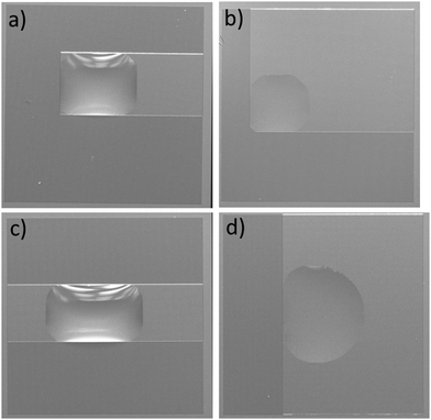
The four types of directional imbibition observed and discussed in this work are shown in Fig. 1. The four possible directions that the liquid can spread from the initial deposited droplet on the surfaces are: left, right, top and bottom. Various combinations of these lead to the four different types of directional imbibition. In Fig. 1a, the liquid only spreads right so we call this unidirectional imbibition (1D). In Fig. 1b, the liquid spreads toward right and top, so we call it bidirectional square imbibition (2Da). In Fig. 1c, the liquid spreads left and right, and we call it bidirectional line imbibition (2Db). Finally, in Fig. 1d, the liquid spreads top, bottom and right, and we call this type tridirectional imbibition (3D).Mechanism
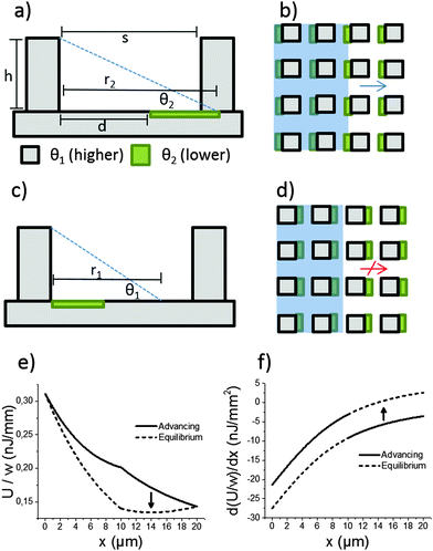
The mechanism of directional imbibition (movement of the liquid in-between the pillars) is explained in Fig. 2. The parameters of the system are chosen so that imbibition is energetically favourable to some directions while a local energy minimum stops the imbibition to other directions. This is achieved by utilizing a lithographically patterned surface energy pattern overlaid on top of square array micropillar topography. The micropillar array is characterized by two important parameters: the row to row spacing (s) and the height of the array (h). Two different surface chemistries are used. The first chemistry (marked grey in Fig. 2) has lower surface energy (higher contact angle, θ1) and the second (marked green) has higher surface energy (lower contact angle, θ2). The lower contact angle coating is patterned so that it is in contact with one pillar and extends partially toward the previous/next pillar row. The parameter to characterize the lower contact angle coating is d, the distance to the lower contact angle area from the previous pillar row (see Fig. 2a). The distance d is compared to the maximum spontaneous reach (r) of the liquid meniscus from a row of pillars. We mark the maximum spontaneous reach on θ1 as r1 and the maximum reach on θ2 as r2 (see Fig. 2a and c).This setup leads to asymmetric imbibition with a certain set of parameters. The direction depicted in Fig. 2a and b is called the advancing direction. The meniscus comes into contact with the more hygrophilic coating, which helps it reach the next row of pillars. The direction depicted in Fig. 2c and d is called the equilibrium direction. The liquid meniscus finds an equilibrium position with the appropriate contact angle in the middle of two pillar rows.
Directional imbibition based on this mechanism is achieved when several conditions are fulfilled. First, the liquid should not get stuck in an equilibrium position in the advancing direction and second, the liquid should not spontaneously advance in the equilibrium direction. The first part is achieved when the following two conditions are fulfilled:
| d < r1, | (1) |
| s < r2. | (2) |
| s > r1. | (3) |
| d < h/tan(θ1), | (4) |
| s < h/tan(θ2), | (5) |
s > h/(tan![[thin space (1/6-em)]](https://www.rsc.org/images/entities/char_2009.gif) θ1). θ1). | (6) |
Oil contact angle ranges, stability and pinning types
The contact line on a regular microstructure can get pinned in two ways as described by Blow and Yeomans:19 either between pillar rows (connected contact lines) or in geometrical valves on areas where the front edge of the meniscus needs to advance (disconnected contact lines). Due to the low surface tension of oils, all oil contact angles in this work were <40°. Because of this, the pinning observed in this work was always of the connected contact line type, as shown in Fig. 2c.Another difference in contact angles between oils and water is the long term stability. For oils it is relatively easy to realize θ2 that is stable over a long time due to the low surface tensions of oils. We observed that a silicon surface oxidized by oxygen plasma remained nearly completely wetting for oils (advancing contact angle less than 10°, irregular droplet shapes) for at least two months when stored in a cleanroom environment. Similarly, the oil contact angles on the fluoropolymer θ1 were stable due to the inertness of a fluorinated surface.
For water, it is not so easy to achieve long term superhydrophilicity at least on planar surfaces. Many naturally occurring completely wetting surfaces, such as noble metals and potentially rare earth oxides, lose their hydrophilicity due to atmospheric hydrocarbon adsorption26 and the hydrophobic recovery of plasma hydrophilized polymers is well known.27
Directional oil imbibition experiments
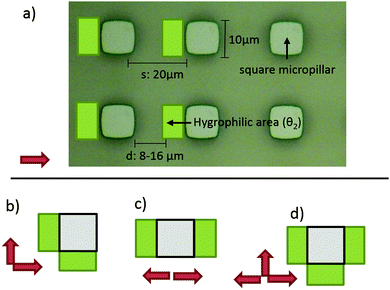
The geometries that we utilized in this study are shown in Fig. 3. The micropillar arrays consisted of 10 μm times 10 μm square pillars in a square lattice with the inter row spacing of 20 μm. Three different heights were utilized: 11.3 μm, 12.5 μm, 16.1 μm. Three different oils were tested: hexadecane (27.5 mJ m−2), tetradecane (26.6 mJ m−2) and dodecane (25.3 mJ m−2).The more hygrophilic coating was completely wetting for all the test oils so θ2 = 0°. The advancing contact angles of the less hygrophilic area were dependent on the oil used. The advancing contact angles (θ1) were 39° ± 2°, 33° ± 2° and 27° ± 2° for hexadecane, tetradecane and dodecane respectively. Finally, for all combinations above, we tested five different d values, 8 μm, 10 μm, 12 μm, 14 μm and 16 μm.
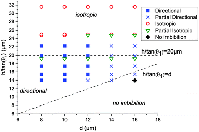
The results of the 45 different combinations of parameters (3 heights, 3 liquids, and 5 d-values) are summarized in Fig. 4. The end states of the experiments were classified into 5 categories: fully directional imbibition, partial directional imbibition, fully isotropic imbibition, partial isotropic imbibition and no imbition. The criteria were as follows: an experiment was classified as fully directional if all four different imbibition types were directional in the manner shown in Fig. 1. If only partial directional character is present (some structures worked but others did not or the imbibition stopped midway), the experiment was classified as partially directional. If all the samples filled all directions regardless of the patterns, the experiment was classified as fully isotropic. If the liquid mostly spreads everywhere, except for a few directions, the experiment was marked as partially isotropic. Finally, an experiment was classified as no imbibition if the liquid did not advance into any direction from the initial droplet. This process is further illuminated in Fig. S1 (ESI†), which shows the end states of two experiments with the corresponding classifications.
The directional imbibition parameter space is shown in Fig. 4. The parameter space is divided into three regions: isotropic imbibition, directional imbibition and no imbibition. The division is based on the conditions (1)–(3) which can be approximated by the conditions (4)–(6). On the coordinate system chosen for Fig. 4, condition (4) translates to h/tan(θ1) > d, condition (5) is always satisfied since θ2 = 0, and condition (6) translates to h/tan(θ1) < 20 μm (since the same spacing of 20 μm was used for all tests). The main artifact of the approximation is that all of the datapoints in Fig. 4 are shifted upward with regard to the approximated conditions. This is because we approximated that r1 = h/tan(θ1) while in reality it is known that for a row of micropillars r1 < h/tan(θ1).14
The experimental data match the theoretical considerations above reasonably well. We observed strictly isotropic imbibition above roughly h/tan(θ1) > 23 μm, as opposed to h/tan(θ1) > 20 μm predicted theoretically. On the isotropic part of the parameter space, the pillar array is too high (or too hygrophilic) compared to the pillar row spacing. Because of this, the meniscus of the equilibrium direction is also able to reach the next row, resulting in isotropic imbibition. On the other hand, either no or only limited imbibition was observed when h/tan(θ1) < d. Here, the height of the pillars is too low (or the contact angle too high) compared to the distance to the completely wetting area. Because of this, the meniscus of the advancing direction never reaches the θ2 area and gets pinned. In-between these areas we observed directional imbibition with most parameters when d = 8 μm, 10 μm or 12 μm. We never observed full directional imbibition when d = 14 μm or 16 μm. The reason for this is unknown. We speculate that it could be due to limitations in the development of the photoresist. The photoresist thickness is roughly the depth of the pillar array +6.2 μm, and as d increases, the size of the opening in the resist decreases leading to high aspect ratios that could develop inefficiently.
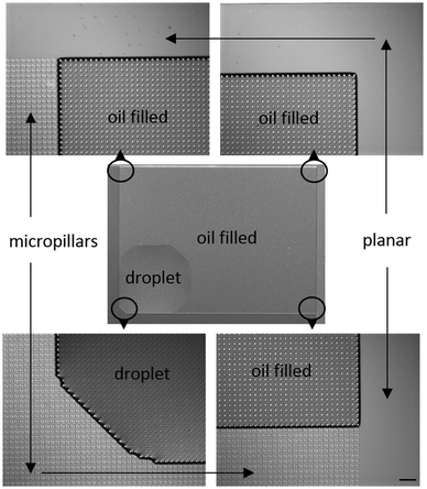
The microscopy images of an end state of an experiment are shown in Fig. 5. The figure shows that the oil has advanced towards top and right until the micropillar array ends, while toward left and bottom the droplet did not move from the initial position. The droplet edges sometimes made faceted shapes and sometimes straight 90° angles, as discussed by Courbin et al.13 and our own previous work.28
The oil droplet itself does also spread from the initial contact position. If we consider that the imbibition has already happened, then the oil droplet is spreading on top of the pillar on a composite surface comprised partly of the oil itself (f1 = 8/9) and partly of θ1 (f2 = 1/9). Utilizing the Cassie formula9 and a θ1 of 33°, we get a Cassie contact angle of ≈11°. This means that the oil droplet spreads to the imbibition directions until this angle is reached.
The imbibition process
The liquid fills the micropillar topography by a two stage imbibition process. The meniscus first makes contact with the next pillar row (like shown in Fig. 2a) on a random spot. After contact is made at one point, the whole row is filled laterally. This type of imbibition process is well known,13 and its kinetics are mostly determined by the slow row to row movement step. The imbibition is driven by the negative capillary pressure and opposed by the viscous drag in the liquid. The capillary pressure is highly position (and direction) dependent for the directional imbibition surfaces. For the 1D imbibition, the capillary pressure as a function of x can be obtained from Fig. 2f and eqn (S6)–(S9) (ESI†) by dividing with the layer thickness. For the 1D with h = 11.3 μm, d = 10 μm, s = 20 μm, θ1 = 39°, θ2 = 0° and γ = 27.5 mJ m−2, the pressure has its lowest value of ≈−280 Pa at x = 10 μm in the advancing direction. The expression for 2Da is the same as that for 1D. In the case of 2Db, the surface chemistry between pillar rows is divided into three parts: the first and the last (s–d) μm is covered by θ2 and the area in-between by θ1 (when d < 10 μm these areas overlap). The 3D case is a mix between the 1D and the 2Db.Videos S1–S4 (ESI†) show the start of the filling processes (from the droplet application) for all four directional imbibition types. The videos are shot in 100 fps and are displayed in real time. The videos are from the same experiments whose end states are shown in Fig. 1. It typically took less than 1s for the droplet to stop moving and after that 5 s–60 s for the whole 1 cm × 1 cm test structure to be filled by capillary imbibition, depending on the wetting type, the parameters and also the location of the initial droplet.
We noticed that the filling rate was a much more variable parameter between samples than the final filling type. A tentative explanation is that small errors in the surface chemistry pattern alignment accuracy are expected to have a big effect in the minimum capillary pressure as explained above. However, small inaccuracies in the alignment are not expected to have an effect in the final filling result for most parameters, excluding those cases where r1 is very nearly the same as d.
Directional water imbibition experiments
All four types of directional imbibition were also achieved with water (see Fig. S2, ESI†). The water experiments were performed on 18.5 μm high micropillars with otherwise identical geometries to the oil imbibition experiments. The advancing contact angle (θ1) between water and the hydroxyl terminated silane was 52°. The oxidized silicon surface (θ2) had a water contact angle of 0°.Design implications
The directional imbibition mechanism explained in Fig. 2 and the results shown in Fig. 4 present a clear path for optimizing the robustness of the directional imbibition filling type. First, the more hygrophilic surface area (θ2) should have as low advancing contact angle as possible in order for eqn (5) to be fulfilled. There are no tradeoff considerations for this parameter.The higher contact angle (θ1) needs to be optimized alongside the height (h), pillar spacing (s) and distance to the more hygrophilic area (d) in order to satisfy eqn (4) and (6). In addition to this, θ1 needs to be low enough to sustain capillary imbibition in the pillar array. Conditions for the latter have been derived from an energy minimization point of view.25 In previous experiments, we noticed that advancing contact angles of roughly 55° and below were able to sustain capillary imbibition on micro and nanopillar surfaces.28 Above this limit the imbibition fronts easily get pinned between pillar rows even if global energy minimization considerations would favour filling. The pinning cutoff is likely related to the 45° degree limit of capillary flow into the bottom corners of the pillars that act as V-shaped wedges.29 The flow in corners is a possible mechanism by which the meniscus can bypass geometrical pinning sites on pillar arrays.
In this study we kept s fixed at 20 μm and varied d from 8 μm to 16 μm. The results showed that the directional imbibition behavior achieved reliable d values from 8 μm to 12 μm, so it is recommended to use these or even lower values. While d values lower than 8 μm were not tested, they can be expected to perform even more reliably and with faster kinetics. Lower d values also make the fabrication procedure less demanding since the openings in the thick photoresist will be larger. The only tradeoffs of very low d values are that the tolerance for errors in aligning gets reduced and that the meniscus in the equilibrium direction comes to rest quite close to the next pillar row. With these considerations, the following set of parameters could be used as guidelines for achieving robust directional imbibition:
| 0 < d < h, | (7) |
| θ2 = 0°, | (8) |
| θ1 < 45°, | (9) |
s > h/(tan![[thin space (1/6-em)]](https://www.rsc.org/images/entities/char_2009.gif) θ1). θ1). | (10) |
In this study we kept the size of the micropillar fixed and altered the height, the contact angles and the d parameter. Due to the contact line pinning occurring mostly between the pillar rows, we do not expect the pillar size to have a big effect on the phenomenon as long as the height and the spacing are kept the same. It is possible that there would be some deviations due to the fine structure of the advancing meniscus based on either the Laplace pressure of the meniscus19 or the solid line fraction of the meniscus.14
4 Conclusion
In conclusion, four different types of directional imbibition were demonstrated. The four types were all the possible cardinal direction combinations available on a square lattice. It might be possible to utilize e.g. a hexagonal array and expand the ideas presented in this work to achieve an even wider array of directional imbibition types. The possibility to control the spreading directions could find use in combination with printing technologies as the typical ink has a surface tension much lower than water, down to the values of the test oils used in this work.Acknowledgements
Financial support from the Academy of Finland (#266820) is acknowledged. The cleanroom work was made in the facilities of Micronova, Centre for Micro and Nanotechnology. The author thanks Mr Mika Latikka for help with photography and Prof. Robin Ras for helpful discussions.Notes and references
- P. Roach, N. J. Shirtcliffe and M. I. Newton, Soft Matter, 2008, 4, 224–240 RSC.
- A. Lafuma and D. Quéré, Nat. Mater., 2003, 2, 457–460 CrossRef CAS PubMed.
- T. L. Liu and C.-J. C. Kim, Science, 2014, 346, 1096–1100 CrossRef CAS PubMed.
- V. Jokinen, L. Sainiemi and S. Franssila, Adv. Mater., 2008, 20, 3453–3456 CrossRef CAS.
- M. J. Hancock, K. Sekeroglu and M. C. Demirel, Adv. Funct. Mater., 2012, 22, 2223–2234 CrossRef CAS PubMed.
- D. Xia, L. M. Johnson and G. P. López, Adv. Mater., 2012, 24, 1287–1302 CrossRef CAS PubMed.
- R. J. Kennedy, Nature, 1070, 227, 736–737 CrossRef.
- Y. Cai, L. Lin, Z. Xue, M. Liu, S. Wang and L. Jiang, Adv. Funct. Mater., 2014, 24, 809–816 CrossRef CAS.
- A. B. D. Cassie and S. Baxter, Trans. Faraday Soc., 1944, 40, 546–551 RSC.
- N. A. Malvadkar, M. J. Hancock, K. Sekeroglu, W. J. Dressick and M. C. Demirel, Nat. Mater., 2010, 9, 1023–1028 CrossRef CAS PubMed.
- J. Li, X. Tian, A. P. Perros, S. Franssila and V. Jokinen, Adv. Mater. Interfaces, 2014, 1, 1400001 CrossRef.
- R. N. Wenzel, Ind. Eng. Chem., 1936, 28, 988–994 CrossRef CAS.
- L. Courbin, E. Denieul, E. Dressaire, M. Roper, A. Ajdari and H. A. Stone, Nat. Mater., 2007, 6, 661–664 CrossRef CAS PubMed.
- V. Jokinen, M. Leinikka and S. Franssila, Adv. Mater., 2009, 21, 4835–4838 CrossRef CAS PubMed.
- T. Kim and K. Y. Suh, Soft Matter, 2009, 5, 4131 RSC.
- K.-H. Chu, R. Xiao and E. N. Wang, Nat. Mater., 2010, 9, 413–417 CrossRef CAS PubMed.
- J. Y. Chung, J. P. Youngblood and C. M. Stafford, Soft Matter, 2007, 3, 1163 RSC.
- D. Xia and S. R. J. Brueck, Nano Lett., 2008, 8, 2819–2824 CrossRef CAS PubMed.
- M. L. Blow and J. M. Yeomans, Philos. Trans. R. Soc., A, 2011, 369, 2519–2527 CrossRef CAS PubMed.
- C. Q. Lai and W. K. Choi, Adv. Mater. Interfaces, 2015, 1400444 CrossRef.
- C. Q. Lai, C. V. Thompson and W. K. Choi, Langmuir, 2012, 28, 11048–11055 CrossRef CAS PubMed.
- O. Bliznyuk, E. Vereshchagina, E. S. Kooij and B. Poelsema, Phys. Rev. E: Stat., Nonlinear, Soft Matter Phys., 2009, 79, 041601 CrossRef CAS PubMed.
- S. M. Kim, D. H. Kang, J. H. Koh, H. S. Suh, H. Yoon, K.-Y. Suh and K. Char, Soft Matter, 2013, 9, 4145 RSC.
- B. Ai, L. Wang, H. Möhwald, Y. Yu, Z. Zhao, Z. Zhou, G. Zhang and Q. Lin, Sci. Rep., 2014, 4, 6751 CrossRef PubMed.
- J. Bico, C. Tordeux and D. Quere, Europhys. Lett., 2001, 55, 214–220 CrossRef CAS.
- D. J. Preston, N. Miljkovic, J. Sack, R. Enright, J. Queeney and E. N. Wang, Appl. Phys. Lett., 2014, 105, 011601 CrossRef.
- V. Jokinen, P. Suvanto and S. Franssila, Biomicrofluidics, 2012, 6, 016501 CrossRef PubMed.
- V. Jokinen, L. Sainiemi and S. Franssila, Langmuir, 2011, 27, 7314–7320 CrossRef CAS PubMed.
- P. Concus and R. Finn, Applied Mathematical Sciences, 1969, 63, 292–299 CAS.
Footnote |
| † Electronic supplementary information (ESI) available. See DOI: 10.1039/c5sm01746g |
| This journal is © The Royal Society of Chemistry 2016 |

